

Page 1
INSTALLATION(INSTRUCTIONS
1221Instructions 11-04-14.doc Page 1 of 5
2009 – Current F-150 flow though console models
Qi Wireless Charging Kit (Kit # FDMC-1221)
For use with Console Tray PN#(9L3Z-19A090-AA) and Mat PN#(9L3Z-1504G34-CB)
Please read thoroughly before starting installation and check that kit contents are complete.
Items Included in the Kit:
Tools & Supplies Needed:
Qi Wireless Charging Module with
F-150 Specific Mat
8’ Power Harness with 3 amp Fuse
4 – Flat Head Torx 1/2" Screws
These Instructions with Template
Removable Consumer Product Label
Plastic Trim Removal Tool
T-10 Torx Driver
Phillips Screw Driver
Center Punch/Scribe Tool
Power Drill
5/32”, 3/16” and 1/2” Drill Bits
Razor Knife
Soldering Iron & Solder
(Recommended)
Tape or Heat Shrink Electrical Tubing
82º Chamfer
*Note this product is designed to work with Qi compatible devices. Please confirm that
your device is Qi compatible before installation. Visit www.brandmotion.com for phone
compatibility guide.
Safety Precautions:
• Work in well ventilated area that is clear of obstructions.
• Secure vehicle with tire chucks in both front and rear of tires.
• Turn vehicle accessories OFF and ensure ignition key is in OFF position.
• Wear safety goggles and snug fitting clothes.
• Use tools only for their intended purpose and which are in good repair.
• Only perform this task if confidence, skill, and physical ability permit.
NOTE: We strive to provide accurate and up-to-date installation instructions.
For additional assistance please call Brandmotion Technical Assistance at (734) 619-1250 then dial 2.
IMPORTANT: Do not place smart keys
within 15cm of charging mat. Vehicle
may not detect key to start vehicle. Do
not place metal objects in tray while
charging.
Page 2
INSTALLATION(INSTRUCTIONS
1221Instructions 11-04-14.doc Page 2 of 5
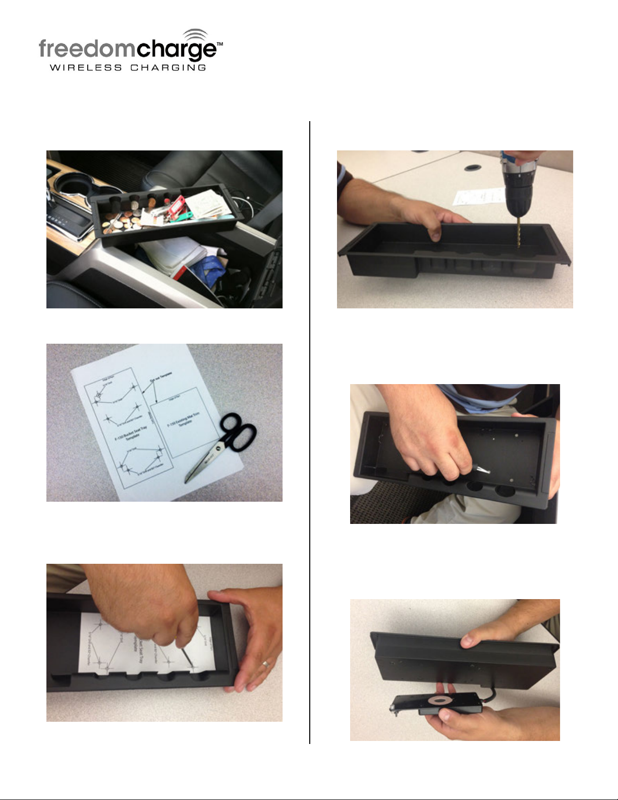
Step 1: Pull out removable storage tray and
remove rubber mat.
Step 2: Cut out provided templates
Step 3: Place module template in tray and
mark the locations for (4) 3/16” and (1)
5/16” hole.
Step 4: Drill the (4) 5/32”, (4) 3/16” and (1)
5/16” holes
Step 5: Use 82º Chamfer bit to chamfer the
(4) 3/16” holes. An X-acto knife can be used
by laying it down on its side and removing
material around the hole.
Step 6: Place FreedomCharge module with
LED poking through 5/16
”
hole. Then align
the (4) 3/16” holes with mounting holes on
module.
Page 3
INSTALLATION(INSTRUCTIONS
1221Instructions 11-04-14.doc Page 3 of 5
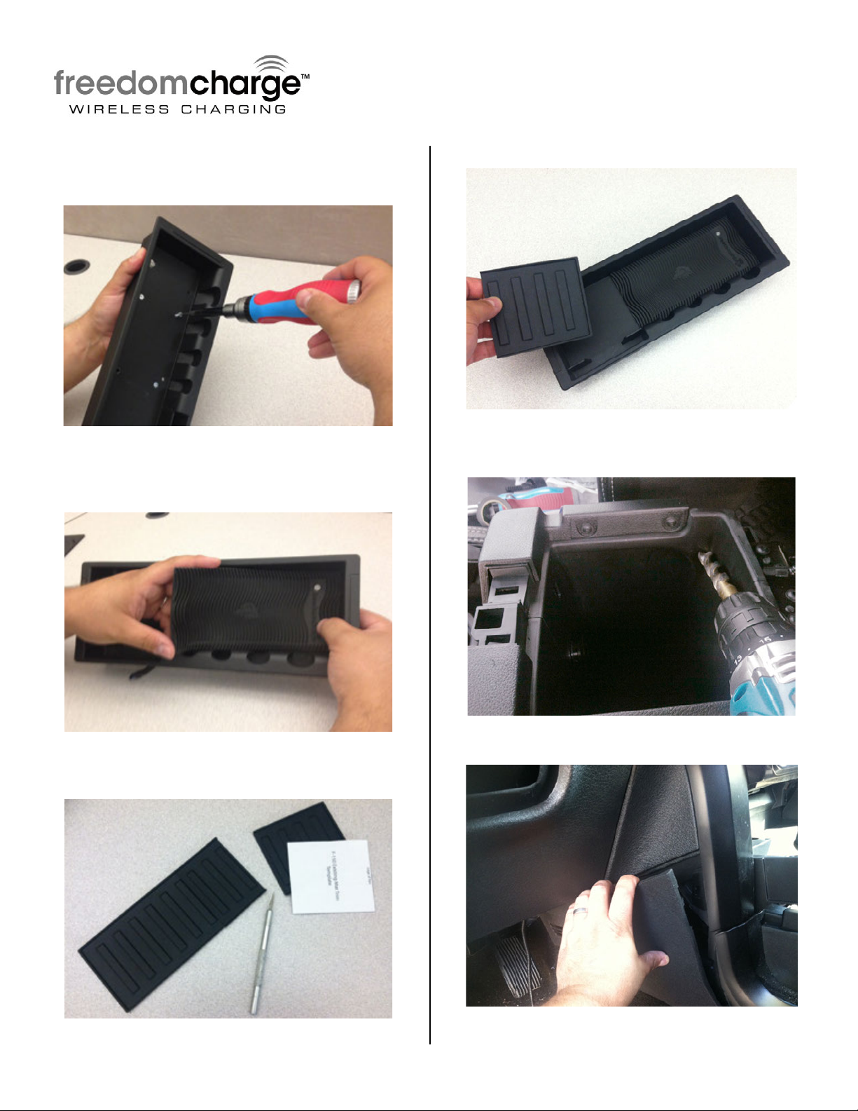
Step 7: Insert the (4) 1/2” Flat Head T-10
Torx Screws through top of tray and into
FreedomCharge module.
Step 8: Install Non-Slip Freedom Charge Mat
to Wireless Charging Module. Place the 4
locator pins in corresponding holes.
Step 9: Trim Factory mat to template
provided.
Step 10: Install cut factory mat
Step 11: Drill ½” hole on driver side of
armrest bin
Step 12: Loosen console side trim
Page 4
INSTALLATION(INSTRUCTIONS
1221Instructions 11-04-14.doc Page 4 of 5
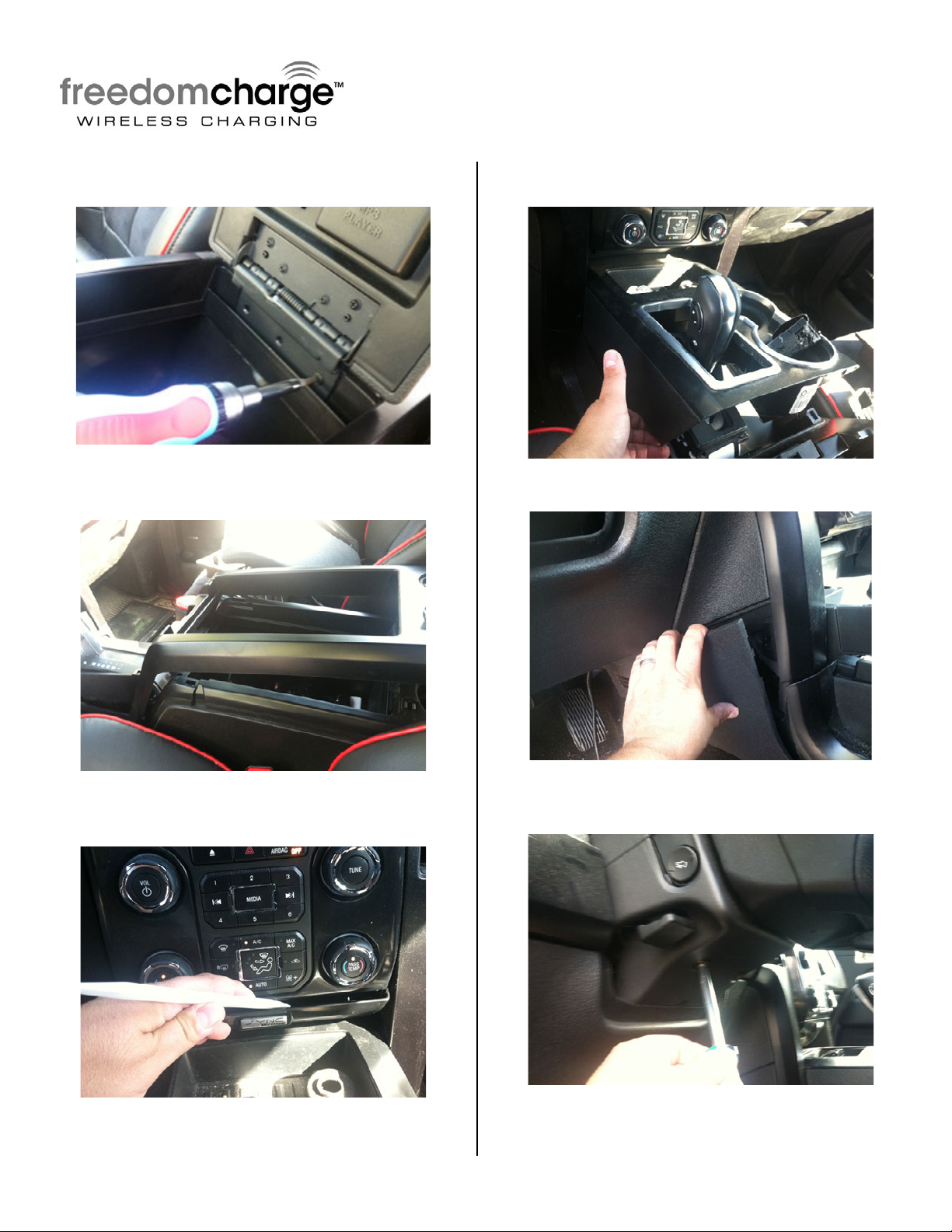
Step 13: Remove armrest lid with Phillips
Screw driver
Step 14: Use plastic trim tool to pop up
console armrest trim surround.
Step 15: Use plastic trim tool to remove
center stack filler plate.
Step 16: Use plastic trim tool to pop up
console surround.
Step 17: Loosen console side trim
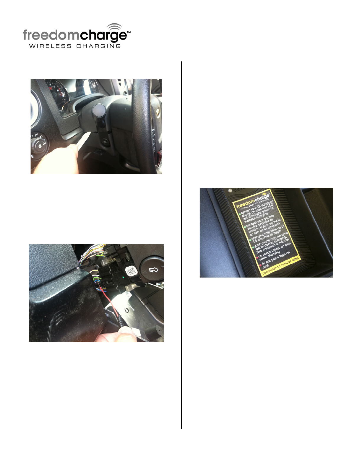
Step 18: Remove screws from lower steering
column cover.
Page 5
INSTALLATION(INSTRUCTIONS
1221Instructions 11-04-14.doc Page 5 of 5
Step 19: Use plastic trim tool to remove
lower steering column cover
Step 20: Splice Red wire of Power Harness to
the Purple/Green wire pin6 (12v ignition) of
the black 7pin ignition switch. Use eyelet
ground loop of the Black wire on Power
Harness to attach to vehicle body (driver
side). RECOMMENDED: Always test wires with
Multi Meter to confirm keyed accessory 12v power,
solder wires and cover with Heat Shrink Tubing.
Step 21: Route Power Harness to rearward
through hole drilled in console bin. Connect
Power Harness to FreedomCharge Module.
*Please note to leave enough slack in harness so
customer can lift tray out of the way to access
items stored under the tray.
Step 22: Test system. LED light will
illuminate Blue once accessories are on.
Once Qi equipped device is placed on
Freedom Charge LED will illuminate Green
and charging begins. *Please note on some
devices syncing may take up to 15 seconds. Coil
locations vary on various devices; move device on
mat until LED illuminates green.
Step 23: Reassemble vehicle. Follow your
disassembly steps in reverse order, taking care not
to bind the harness wiring when reinstalling trim.
Step 24: Place removable consumer product
label on center of mat.
 Loading...