

Page 1
9650 Instructions 2-11-14.doc Page 1 of 2
9002-9650 Installation Instructions (Slimline 3.5” Auto Dimming
Display Wedge Mount Mirror with HomeLink)
IMPORTANT: Check kit contents and read instructions before installing. For the latest full color instructions please visit
www.brandmotion.com
Kit Contents
Slimline Auto Dimming Mirror with 3.5” Display & HomeLink Mirror Harness
Homelink Programming and Information Guide These Instructions
Mirror Mounting
NOTE: This mirror has a Wedge/ D-tab style mounting base; please check our Application Guide to ensure it is compatible with your
vehicle. Additionally, Brandmotion offers windshield mirror adapter brackets, Kit # 5000-VWAB (some Volkswagen vehicles) and Kit
#5000-CAMLOCK (some Honda & Subaru vehicles), available separately.
NOTE 2: In some cases, it may be necessary to remove a cover to access the wedge mount on the windshield and/or modify the
cover slightly to clear the mirror mount. Additionally, if your vehicle is equipped with a mirror cover, mirror adjustability may be
restricted.
To install:
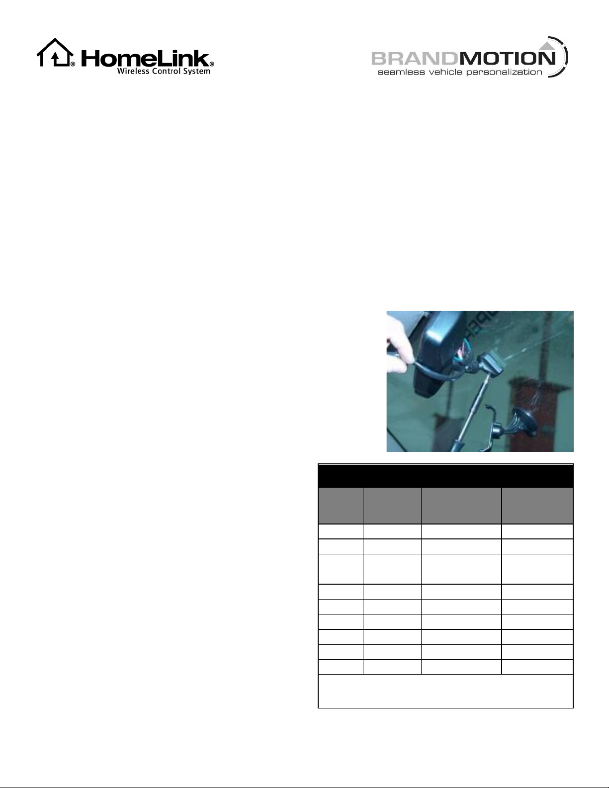
1. Loosen vehicle mirror screw using a T20 Torx driver and remove
existing vehicle mirror.
CAUTION: Do not twist mirror as windshield damage could result.
2. Carefully slide supplied Mirror onto windshield tab.
3. Torque supplied Mirror screw to 1.8 Nm (16 lb-in) and do not exceed
2.2 Nm (19.5 lb-in).
Mirror Wiring
1. Use a multimeter to test for vehicle Igniton (+) and Reverse (+)
signals. Typical locations are behind the driver or passenger side kick
panel or under the dash. Set parking brake, start vehicle, and have
an assistant shift into Reverse while you test for Ignition and
Reverse signals.
2. Plug Mirror Harness into Mirror and route beneath
headliner and down the A-pillar closest to the
Ignition and Reverse signal locations.
3. Splice Mirror Harness wires to the following required
connections:
Red - Ignition controlled power 12v+ when key is
ON
Black - Chassis ground. A ground bolt is commonly
found in the front kick panel area with other
wires attached; in some cases you may
need to supply a new screw.
Green - Connect to Reverse (+) 12V power.
NOTE: While not a required connection, connecting Reverse
disables the vehicle’s auto dim function while vehicle is in reverse.
4. Connect female RCA plug on supplied Mirror Harness
to male camera RCA.
Mirror & Mirror Harness Pinout
PIN
MIRROR
WIRE
COLOR
MIRROR
HARNESS
WIRE COLOR
FUNCTION
1
Purple
White
Video (+)
2
White
Brown
Video (–)
3
N/A
N/A
Not used
4
N/A
N/A
Not used
5
N/A
N/A
Not used
6
Red
Red
Ignition (+)
7
Orange
Green
Reverse (+)
8
Black
Black
Ground
9
N/A
N/A
Not used
10
N/A
N/A
Not used
These instructions only pertain to functions on the supplied
mirror and do not support other vehicle features.
Page 2

9650 Instructions 2-11-14.doc Page 2 of 2
Camera Requirements
The camera signal must be strong enough for the mirror to detect signal when reverse is engaged. We recommend
that the camera be connected to mirror prior to installation to confirm compatiblity. Best results are on cameras that
have a 0.8- 1.6v DC coming out of video composite lead (commonly a yellow RCA jack). Depending on camera output it
may require reverse to be supplied by a 12v switched ignition rather than reverse feed. To test this use a multimeter set
to DC and connect the (-) lead to the camera RCA shield and the (+) lead to the camera RCA tip with the camera
powered ON.
Powering Up the Camera
The mirror stays ON for over 1 second when reverse is disengaged, and if the camera is connected to the reverse
tail lamp then the screen will flash Blue. If the camera does not power up instantly when the vehicle is shifted into
reverse, the screen will not detect the camera and will not display an image. For these reasons we recommend that the
camera be connected to Ignition (+).
Test Mirror
Set parking brake, start vehicle, and shift into Reverse. If image appears in the LCD display, all connections have
been made properly.
Temporary Monitor Manual Shut Down:
If while in reverse you require to turn OFF the camera monitor, simply press and release the POWER button on the
back side of the mirror. (Note: once reverse is disengaged the mirror will go back to normal operation and will turn
ON next time reverse is engaged).
NOTE 1: Mirror Voltage Requirements
The supplied Mirror must see a voltage of 12.5v DC or better on the Reverse trigger lead. In the event that the
signal is too low the signal quality may be affected drastically when the vehicle is running.
To correct low Reverse signal power, the voltage must be raised using a Single Pull Dual Throw Relay.
Relay Wiring:
30 To mirror Reverse trigger (Green lead)
85 Chassis Ground
86 Reverse trigger from vehicle (reverse lamp)
87 High current Ignition controlled power lead +
87a Not used
Connect the rest of the Mirror Harness wires as instructed above.
NOTE 2: For Ford vehicles only
If the vehicle has a separate display on the IP for the compass and it displays “– –“after the OE mirror is removed,
further steps are necessary in order for it to function again. You must supply two 9’ 20-gauge wires (recommended:
one red and one yellow). Splice the wires to the location from which you removed the vehicle’s mirror connector and
splice their opposite ends to the vehicle’s mirror connector that will be relocated along with the mirror circuit board.
For more details, refer to Section 6 of 1008-9520 kit instructions at www.brandmotion.com
HomeLink Set Up and Operation
1. Refer to supplied HomeLink “Programming and Information Guide.”
2. Keep HomeLink “Programming and Information Guide” in vehicle for future reference.
This HomeLink device is approved for use only in the United States and Canada.
 Loading...