

Page 1

!
INSTALLATION INST R U C T IO NS
8521 Instructions 7-26-13.doc Page 1 of 5
OEM Recessed Lip Camera with Harness and Auto Dimming Mirror
(Kit part number 9002-8521)
Please read thoroughly before starting installation
and check that kit contents are complete.
Items Included in the Kit
Tools & Supplies Required:
Bubble bag containing:
Camera with Mount (in zip lock bag)
Camera Harness
Mirror
Mirror Harness
Chassis Harness
Zip lock bag containing:
12 Zip Ties
2 Rubber Nuts
2 Bolts
2 Sets of T-taps
Orange & White Exterior Dimming Wires
(If needed)
Zip lock bag containing:
These Instructions
Self-adhesive Template
Phillips Screwdriver
T20 Torx Driver
Center Punch
1/8” & 5/16” Drill Bits
5/8” Drill Bit or Center Hole Saw
Power Drill
Roto Tool
File
Multi-meter or computer safe test light
Wire Ties or Electrical Tape
Wire Crimper
Ground Eyelet
(Recommended)
Soldering Iron
Solder
(Recommended)
Plastic trim removal tool
Rubber Grommet or Silicone Caulk
(Recommended)
Vehicle service manual (If needed)
Additional Parts That May Be Needed (see Application Guide. Parts separately):
5000-VWAB Volkswagen mirror mount adapter
5000-CAMLOCK Honda/ Subaru mirror mount adapter
Safety Precautions:
• Work in well ventilated area that is clear of obstructions.
• Secure vehicle with tire chucks in both front and rear of tires.
• Turn vehicle accessories OFF and ensure ignition key is in OFF position.
• Wear safety goggles and snug fitting clothes.
• Use tools only for their intended purpose and which are in good repair.
• Only perform this task if confidence, skill, and physical ability permit.
NOTE: We strive to provide accurate and up-to-date installation instructions. For the latest full color
instructions, as well as an installation video, please visit www.brandmotion.com
Page 2
!
INSTALLATION INST R U C T IO NS
8521 Instructions 7-26-13.doc Page 2 of 5
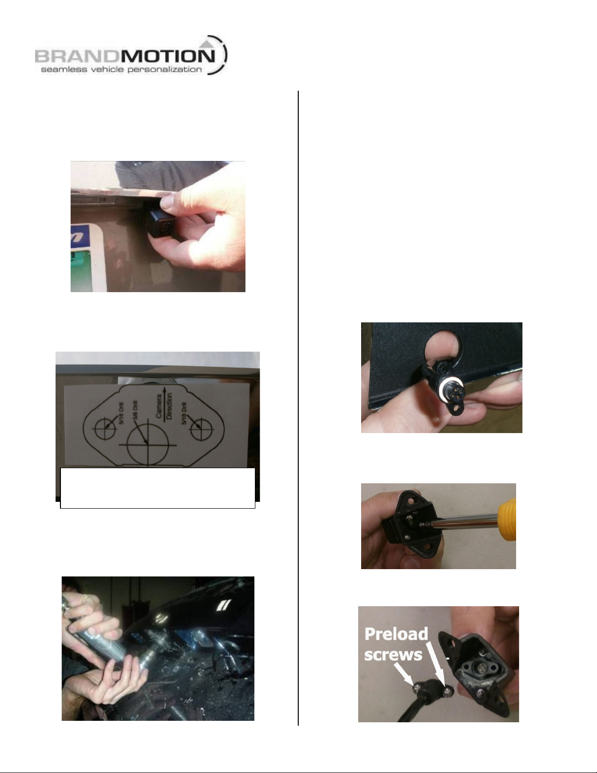
Step 1: Place Camera Mount in desired position to
confirm fitment. (IMPORTANT: Some states
prohibit items blocking the vehicle license plate;
check local authorities to confirm legal status for
your specific application).
Step 2: Peel adhesive backing from supplied
Camera Mount Template and apply to the desired
location making sure that the camera direction is
correct.
Step 3: Use a Center Punch to mark the centers of
the required three holes and drill three pilot holes
using a 1/8” drill bit. NOTE: If your vehicle has a
liftgate panel/trunk trim cover, it must be removed.
Step 4: Drill two 5/16” holes for the camera
mounting bolts and one 5/8” hole for the camera
harness. Use a Deburring Tool or Round File to
smooth edges.
Step 5 (if necessary): Using a 5/8” drill bit, drill an
opening in the trunk or liftgate for the head of the
Camera Harness to pass through. Insert Camera
Harness head through the backside of the hole so
that the gray connector end of the Camera Harness
is inside the trunk or liftgate. (RECOMMENDED:
Protect Camera Harness with a rubber grommet or
by applying a small amount of silicone caulk to the
area that comes into contact with the edges of the
hole. Additional recommendation: If drilling
through sheet metal, apply a Corrosion Inhibitor.)
Step 6: Route head of Camera Harness through the
pass-through you made with the Template.
Step 7: Use a Phillips Screwdriver to remove the
two screws provided in the Camera to secure the
head of the Camera Harness onto the Camera.
Step 8: Preload the screws into the Camera
Harness connector.
NOTE: If self-adhesive Template is missing or
damaged, cut out the image above and affix
with Masking Tape.
Page 3
Step 9: Align the Camera Harness head so the key
Mirror Harness Pinout
1 - 4
N/A
N/A
*5
Orange
Exterior Auto Dimming (+)
6
White
Video +
7
Brown
Video -
8
Black
Ground
9
Green
Reverse Signal 12V+
10 - 12
N/A
N/A
13
Red
Ignition Controlled 12V+
14 - 15
N/A
N/A
*16
White
Exterior Auto Dimming (–)
CAUTION:
White dot
lines up with the slot in the camera, and plug in the
connector. Snug the supplied screws with a Phillips
Screwdriver to create a watertight seal but do not
over tighten.
Step 10: Mount the Camera using the supplied
hardware. Insert the two Rubber Well Nuts into the
outer 5/16” camera mount holes.
Step 11: Thread the two supplied Bolts through
the Camera Mount and into the Well Nuts using a
Phillips Screwdriver but do not tighten the Bolts all
the way down just yet.
Step 12: Remove vehicle mirror.
CAUTION: Removing the mirror can cause
damage to the windshield.
Step 13: Attach supplied Mirror to the windshield
using a T20 Torx Driver. This mirror has a Wedge/
D-tab style mounting base. Please check our
compatibility chart to make sure it is compatible
with your vehicle (adapters are available for
specific applications separately).
IMPORTANT: Torque for the mirror screw that
attaches to the windshield tab is 1.8 Nm (16
lb-in) and cannot exceed 2.2 Nm (19.5 lb-in).
Step 14: Determine location of vehicle Ignition
power and Ground. Using a vehicle specific service
guide/wiring diagram and a Digital Multi-Meter or
Computer-Safe Test Light, locate which side of the
vehicle contains the wires into which you will
connect Mirror Harness wiring (see chart below).
"#$%&''&%"(# "#$%)*+%"(#$
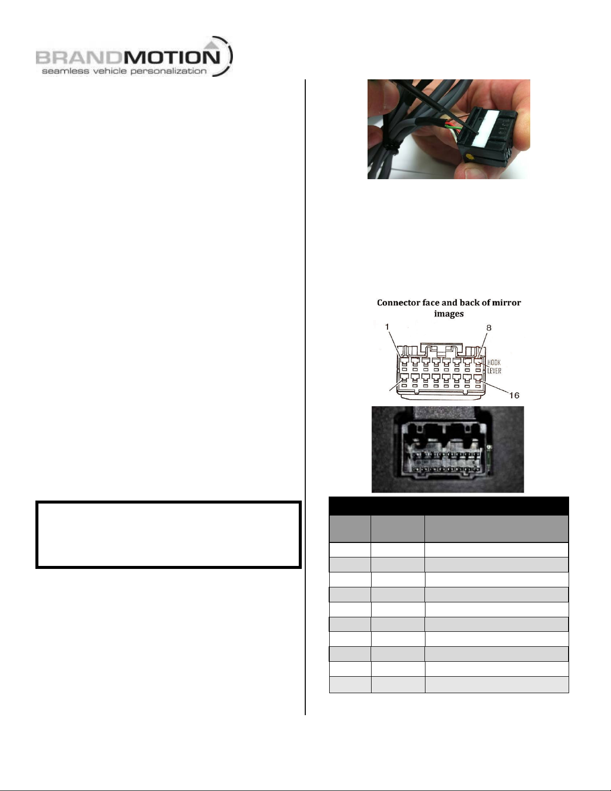
Step 16: Insert supplied Orange lead into 16-pin
connector cavity 5 and White lead into 16-pin
connector cavity 16 until they click into place. If
they do not seat initially, use Delphi Terminal Tool
12094429 or a small flatblade watch repair
screwdriver to press the terminals fully into the
connector. Next, press down on the TPA to lock the
terminals.
identifies
cavity 1
Once correct wires have been identified, turn
Ignition key OFF and DO NOT TURN key back ON
until the install has been completed (Step 25).
(Follow Steps 15-17 only if your vehicle is
equipped with Exterior Auto Dimming
Mirrors. Otherwise, proceed to Step 18).
Step 15: Located on the bottom side of the 16-pin
mirror connector is a rectangular white bar called a
Terminal Position Assurance (TPA) tab. Use Delphi
Terminal Tool 12094429 or a Small Flatblade Watch
Repair Screwdriver to release the TPA as shown.
The TPA will only lift about 1/10
8521 Instructions 7-26-13.doc Page 3 of 5
th
of an inch.
WIRE
PIN
COLOR FUNCTION
Page 4
!
INSTALLATION INST R U C T IO NS
8521 Instructions 7-26-13.doc Page 4 of 5
Step 17: Follow the appropriate supplied charts to
splice the Orange & White leads to wires in your
existing vehicle mirror harness:
Wire
Color
Ford Mirror Connector
7 Pin
10 Pin
16 Pin
Function
Orange
Cavity 4
Cavity 8
Cavity 11
Mirror Feed +
White
Cavity 5
Cavity 7
Cavity 15
Mirror Feed –
Wire
Color
Dodge Mirror Connector
16 Pin
Function
Orange
Cavity 11
Mirror Feed +
White
Cavity 15
Mirror Feed –
For vehicles not listed, use a Digital Multimeter
to identify the wires in the existing vehicle mirror
harness that feed the Exterior Auto-Dimming
Mirrors. Splice supplied Orange lead to AutoDimming (+) and White lead to Auto-Dimming (–).
Step 18: Plug the black 16-pin connector into the
rear of the mirror.
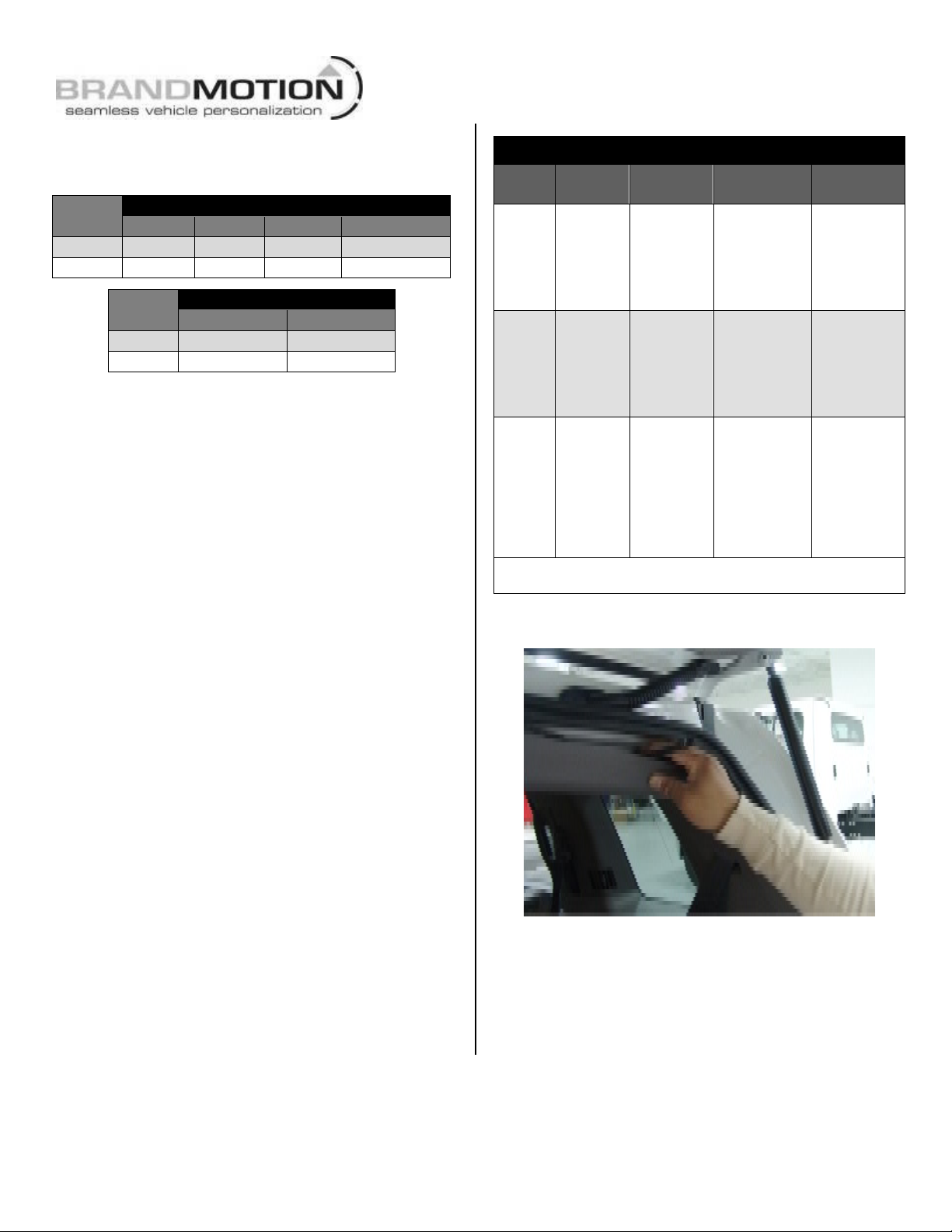
Step 19: Route supplied Mirror Harness under the
headliner and down the A-pillar nearest vehicle
power and reverse signal.
Step 20: Splice the red and green Mirror Harness
leads into the corresponding vehicle wires and the
black wire to chassis ground. (Note: Soldering
recommended or use supplied T-taps as optional
connection method). RECOMMENDED: Attach an
eyelet to the black ground wire.
Red - Ignition controlled power 12v+ when key
is turned ON and 14.4v or better when
vehicle is running.
Black - Chassis ground.
Green - Connect to Reverse + signal (backup
lamp).
Note: If installing in a Ford vehicle with a separate
compass display on the instrument panel and
it displays “– –“ after the OE mirror is
removed, you must follow online steps in
Section 6 of 1008-9520 instructions posted at
www.Brandmotion.com in order for it to
function again.
Mirror Harness Connection Chart
Wire
Color
Polarity
Function
Description
Location
note
Red
12v +
Ignition
controlled
power
This lead
displays 12
volt + when
the key is in
the RUN
position
Commonly
found on
main
Ignition
harness.
Black
(–)
Ground
Chassis
ground
A ground
bolt is
commonly
found in the
front kick
panel area.
Green
12v +
Reverse
trigger
(Backup
Lights)
This lead is
activated
when the
vehicle is
engaged into
Reverse
Commonly
found in
front kick
panel area
on harness
coming
from rear of
vehicle.*
*If Reverse cannot be located, connect the both the Red and Green
wires to Ignition power.
Step 21: Route Camera Harness towards the side
of the vehicle that supplies power.
Step 22: Connect Camera Harness to supplied
Chassis Harness. The optimal location for this
junction may occur at the top of the liftgate or the
inner edge of the trunk. (Note: Most vehicles have
existing wires passing through this area; use this
route if at all possible).
Page 5
!
INSTALLATION INST R U C T IO NS
8521 Instructions 7-26-13.doc Page 5 of 5
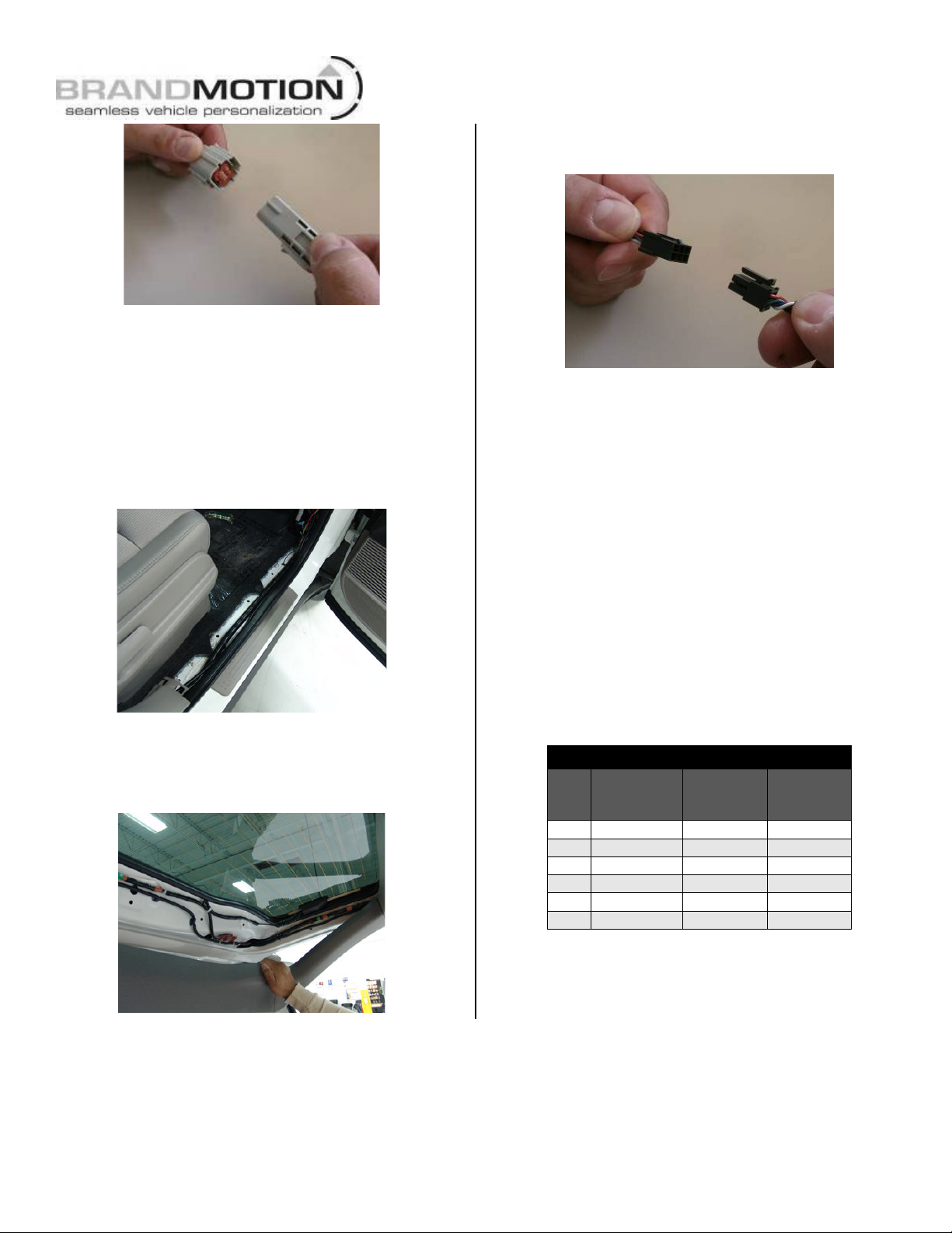
Step 23: Route Chassis Harness forward. It may
be necessary to remove sill plates, pillar covers,
seat bottoms, side panels, etc. In some cases even
the seatbelt bolts at the bottom of the pillars must
be removed.
CAUTION: Any bolts removed for safety devices
must be retightened to manufacturer’s specified
torque specifications). Use a Plastic Trim
Removal Tool to avoid damage to trim pieces.
Step 24: Secure Camera Harness to existing
vehicle wiring using supplied Wire Ties. This will
minimize chance of binding or otherwise damaging
the harness
Step 25: Connect Chassis Harness to supplied
Mirror Harness.
Step 26: Test the system. Inspect that all
connections are proper and secure. Clear all loose
items removed from the area around the vehicle
and turn ignition key ON to test system. Once
Reverse gear is engaged the camera image should
appear on the mirror.
Step 27: Secure Chassis Harness and Mirror
Harness with supplied Zip Ties. If necessary, coil
excess harness wire and secure with Zip Ties.
Attach to existing vehicle wiring where possible.
Step 28: Adjust camera aim. With the aid of an
assistant, move camera to desired view, and
tighten the Bolts that hold the camera in place.
Step 29: Reassemble vehicle. Follow your
disassembly steps in reverse order, taking care not
to bind the harness wiring when reinstalling.
Pinout Reference Chart
PIN
#
FUNCTION
CAMERA
HARNESS
COLOR
CHASSIS
HARNESS
COLOR
1
Video (+)
Yellow
White
2
Shield
White
Blue
3
Reverse
Blue
Green
4
Video (–)
Brown
Brown
5
Ground
Black
Black
6
Ignition
Red
Red
OPERATING!INSTRUCTIONS!
Temporary Monitor Manual Shut Down. If while in Reverse you require to turn OFF the camera
monitor, simply press and release the POWER button on the mirror. (Note: once Reverse is disengaged
the mirror will go back to normal operation and will turn ON next time Reverse is engaged).
 Loading...