

Page 1

INSTRUCTION MANUAL
Page 1
Instruction Manual for TBRD (K8421)
11/26/2015
NSW Schools / TAFE - TBRD
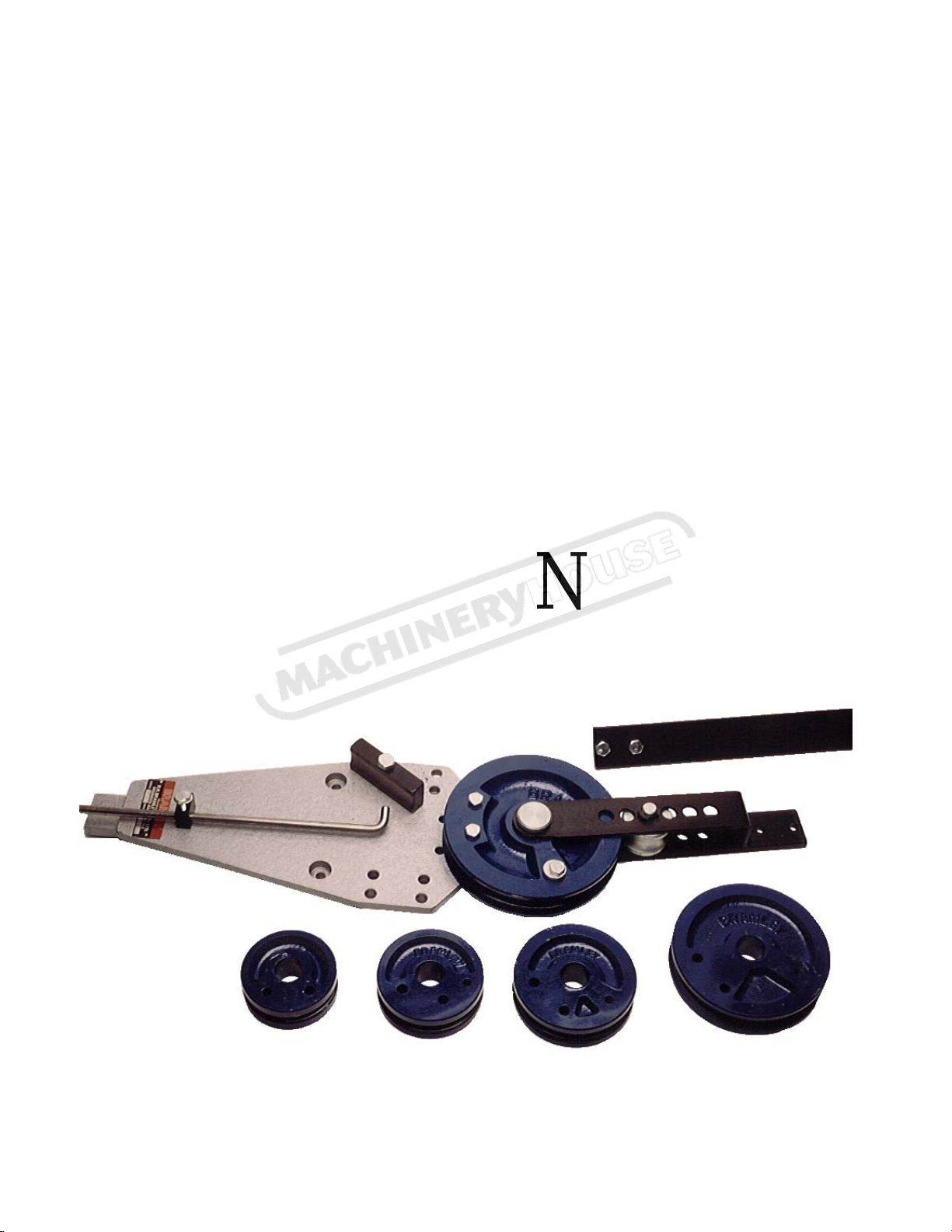
Manual Tube Bender
1/2” - 1” Round
K8421
Page 2
R.R. BRAMLEY & CO. LTD.
Page 2
Instruction Manual for TBRD (K8421)
11/26/2015
ESTABLISHED 1921
TELEPHONE 09 579 2036 FACSIMILE 09 525 0735 EMAIL [email protected]
184 MARUA ROAD, MT WELLINGTON, AUCKLAND NEW ZEALAND
P.O. BOX 14-114, PANMURE, AUCKLAND, NEW ZEALAND
OPERATING INSTRUCTIONS & PARTS
LIST
MANUAL
TUBE BENDER
TELEPHONE: 2-9534-1244 FACSIMILE: 2-9534-6932 EMAIL: [email protected]
AUSTRALIAN OFFICE
60 BARRY AVENUE, MORTDALE, NSW 2223, AUSTRALIA.
Page 3
P.O. BOX 151, MORTDALE, NSW 2223, AUSTRALIA
Page 3
Instruction Manual for TBRD (K8421)
11/26/2015
R.R BRAMLEY & CO LTD
Product No 64: MANUAL TUBE BENDER
DWG# DESCRIPTION MATERIAL QUANTITY
1 Body 1/2” MS Profile Cut 1
2 Foot Base MS: 50 x 16 1
2a Vice Clamp Block MS: 50 x 16 1
3 Low Support Roller MS: 50 x 10 1
4 Upper Support Roller MS: 50 x 5 1
5 Guide Tube Roller BMS: 2 1/4” DIA 1
6 Pin Guide Roller BMS: 16mm or 5/8” DIA 1
7a 1/2” Round Former Iron Casting BRY 100 1
7b 5/8” Round Former Iron Casting BRY 112 1
7c 3/4” Round Former Iron Casting BRY 130 1
7d 7/8” Round Former Iron Casting BRY 170 1
7e 1” Round Former Iron Casting BRY 200 1
8 Pivot Pin BMS: 1 1/8” DIA 1
9 Washer CAM BMS: 25mm DIA 1
10 Guide Block BMS: 40 x 19 1
11 Bar Stop Slide BMS: 32 x 15 1
12 Bar Stop BMS: 10 DIA 32 x 3mm plate 1
13 Handle MS: 50 x 5 1
ACCESSORIES
20 1 1/8” Round Former Iron Casting BRY 235 1
21 1/2” Square Former Iron Casting BRY 130 1
22 5/8” Square Former Iron Casting BRY 170 1
23 3/4” Square Former Iron Casting BRY 200 1
24 7/8” Square Former Iron Casting BRY 235 1
25 1” Square Former Iron Casting BRY 235 1
26 Flat Former Iron Casting BRY 200 1
27 Square / Flat Guide BMS: 2 1/4” DIA 1
Page 4

Page 4
Instruction Manual for TBRD (K8421)
11/26/2015
MANUAL TUBE BENDER ASSEMBLY AND OPERATION
Upon receipt of your new Tube Bender, assemble the Handle to the Tube Bender
Roller Support with the bolts supplied (see Figure 2 and 3).
Figure 3 shows the Bender Body with holes (A) drilled in the Base Foot and the
Vice Clamp Block. These are for mounting the Bender Unit permanently to a
Work Bench. Alternatively temporarily in a Vice by holding the Vice Clamp
Block.
The Holes marked (B) in Figure 1 are used to position the Guide Block (64/10).
This Guide Block can be positioned anywhere over the eight holes to achieve the
desired type of bend or radius. By moving the Guide Block from one side to the
other, the Bender may be operated in either a clockwise or counter clockwise
direction.
The Holes marked (C) are used for securing the Former to the Body of the
Machine. The Body offers two options for positioning the Former. The outside
Holes are used for the small Formers and the inside Holes are used for the larger
Former. The larger Formers can be located in both sets of Holes but unless a large
bend angle is required, it is not recommended to locate the larger Former in the
outer two Holes.
The Hole marked (D) is securing Hole for the Bar Stop Assembly. This should be
bolted into position when you receive your machine.
Figure 2 shows the Tube Roller Support Frame and Handle assembled. Early
models had four Holes for the location of the Guide Roller, more recent models
have six. This allows better bending on the 1/2” and 5/8” Round Tube.
Figure 3 is a schematic diagram showing a side of elevation of the assembled
Bender. To change a Former it is a simple matter of removing the Pivot Pin. Once
the Pivot Pin has been removed, the Support Assembly (Fig.2) can be removed
leaving the Former bolted to the Body. Simply unbolt the Former and replace it
with the size Former you require. Replacing the Support Assembly is a reversal of
the removal procedure.
The Guide Roller can be repositioned to achieve the type or radius of bend you
require.
Page 5
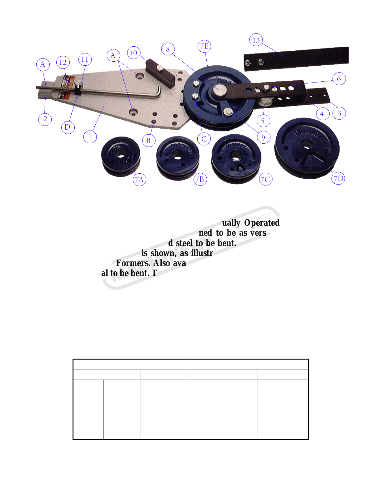
FIGURE 1
Page 5
Instruction Manual for TBRD (K8421)
11/26/2015
Thank you for purchasing the Bramley Manually Operated Tube Bending
Machine. This Machine has been designed to be as versatile as possible to
allow a large variety of tube and steel to be bent. The Machine above is the
Model “A” Bender and is shown, as illustrated (Fig 1), with the 1/2”, 5/8”,
3/4”, 7/8” and 1” Formers. Also available are Formers that will allow other
sizes of material to be bent. These are listed in Table A.
When order spare parts please refer to parts list (Table B). The parts are
numbered on Figure 1 to allow easy identification of parts required.
TABLE A
ROUND FORMERS SQUARE FORMERS
TUBE SIZE BENDING DIA TUBE SIZE BENDING DIA
1/2" 12.7mm 76 1/2" 12.7mm 108
5/8" 16.0mm 94 5/8" 16.0mm 140
3/4" 19.0mm 108 3/4" 19.0mm 170
7/8" 22.2mm 140 7/8" 22.2mm 196
1" 25.4mm 170 1" 25.4mm 190
1 1/8" 28.6mm 196
Page 6

Page 6
Instruction Manual for TBRD (K8421)
11/26/2015
 Loading...