

Page 1
8G.51.09.00/10.05
INSTALLATION MANUAL
BrainQ RSC/2
BrainQ RSC/2 Thermostat
Page 2

GB English
Page 3
GB-3
Contents
General safety instructions............................................................................... GB-4
Safety measures for EMC - compliant installation ........................................... GB-4
Recommended cable cross-sections and cable len gths.................................. GB-5
Installation of the thermostat
........................................................................ GB-5
Mounting location ............................................................................................. GB-5
Connection to the ATAG boiler ........................................................................ GB-6
Connection panel ............................................................................................. GB-6
Electrical connection ........................................................................................ GB-6
Accessories
Outside sensor ................................................................................................. GB-7
Resistance values of outside sensor depending on temperature.................... GB-7
Commissioning of the thermostat
................................................................ GB-8
Code input..................................................................................................... GB-8
Alarm messages
............................................................................................. GB-9
Parameter synoptic
...................................................................................... GB-10
Overview of installer parameters
and adjustment options
............................................................................... GB-11
HYDRAULIC Level...................................................................................... GB-11
SYSTEM Lev el............................................................................................ GB-11
DOMESTIC HOT WATER Level................................................................. GB-12
UNMIXED CIRC. Leve l ............................................................................... GB-12
ALARM MESSAGE Level ........................................................................... GB-13
SENSOR CALIBR ATION Level .................................................................. GB-13
Appendix installation examples
Room control with BrainQ RSC + outside sensor ...................................................II
Room control with BrainQ RSC + outside sensor 100% weather dependant....... IV
Room control with BrainQ RSC + outside sensor + header.................................. VI
Room control with BrainQ RSC + outside sensor + cylinder .............................. VIII
Room control with BrainQ RSC + outside sensor + cylinder* ................................ X
Room control with BrainQ RSC + outside sensor + header + cylinder................ XII
Room control with BrainQ RSC + outside sensor + header + cylinder*..............XIV
GB
Page 4
GB-4
General safety instructions
All electrical connections and safety
measures have to be carried out by a
specialist in due consideration of valid
standards and VDE-guidelines as well as
the local regulations.
Important!
Disconnect from mains power before
opening.
Unauthorised attempts under voltage
may damage the control or cause
dangerous electrical shocks.
Safety measures for EMC -
compliant installation
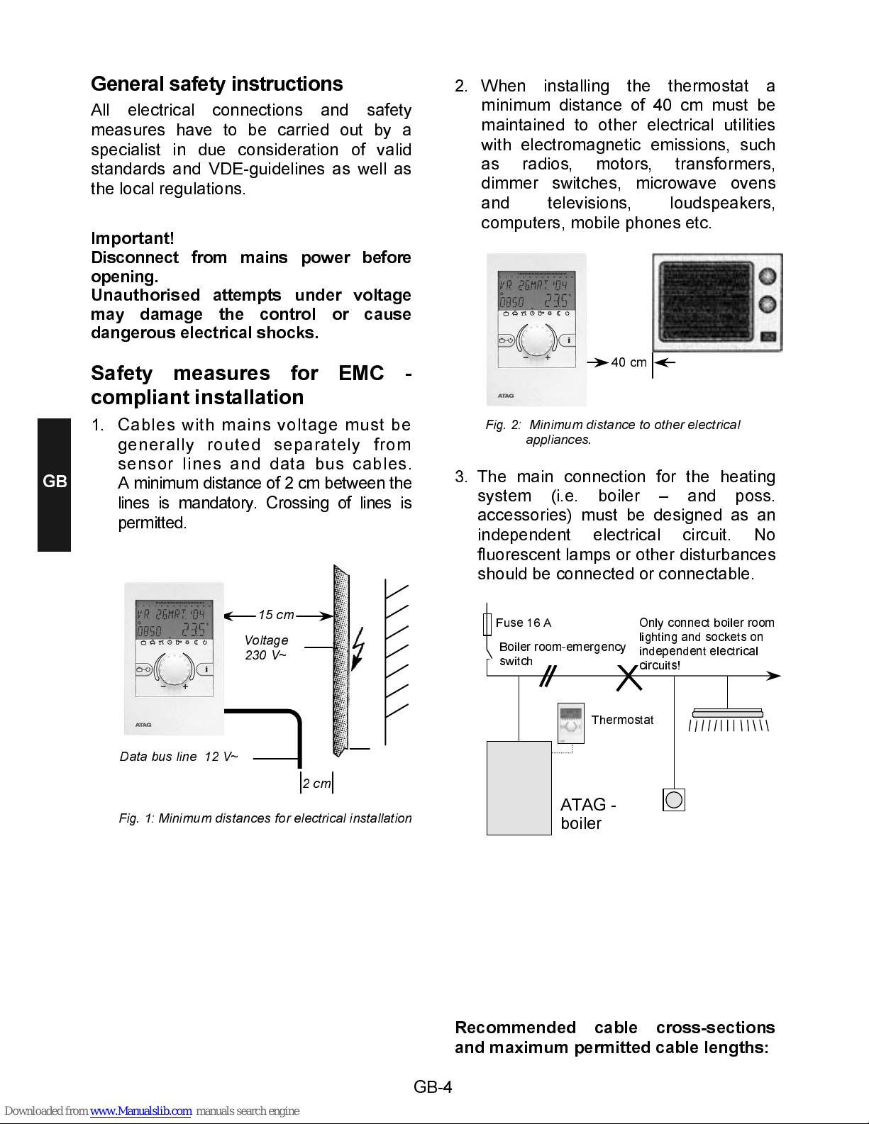
1. Cables with mains voltage must be
generally routed separately from
sensor lines and data bus cables.
A minimum distance of 2 cm between the
lines is mandatory. Crossing of lines is
permitted.
2. When installing the thermostat a
minimum distance of 40 cm must be
maintained to other electrical utilities
with electromagnetic emissions, such
as radios, motors, transformers,
dimmer switches, microwave ovens
and televisions, loudspeakers,
computers, mobile phones etc .
3. The main connection for the heating
system (i.e. boiler – and poss.
accessories) must be designed as an
independent electrical circuit. No
fluorescent lamps or other disturbances
should be connected or connectable.
Recommended cable cross-sections
and maximum permitted cable lengths:
Fuse 16 A
Boiler room-emergency
Only connect boiler room
lighting and sockets on
independent electrical
circuits!
Thermostat
ATAG -
boiler
Fig. 1: Minimum distances for electrical installation
15 cm
Voltage
230 V~
Data bus line 12 V~
2 cm
40 cm
Fig. 2: Minimum distance to other electrical
appliances.
GB
Page 5
GB-5
For the data bus line
Cross-section: 0.6 mm
Maximum permitted cable length: 50 m
Longer connecting cables should be
avoided in order to reduce the risk of
faults.
Installation of the thermostat
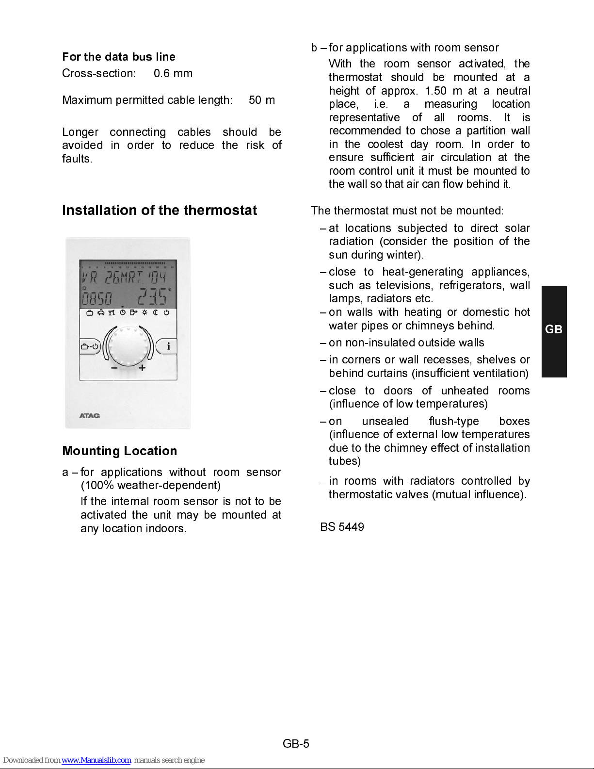
Mounting Location
a – for applications without room sensor
(100% weather-dependent)
If the internal room sensor is not to be
activated the unit may be mounted at
any location indoors.
b – for applications with room sensor
With the room sensor activated, the
thermostat should be mounted at a
height of approx. 1.50 m at a neutral
place, i.e. a measuring locatio n
representat ive of all rooms. It is
recommended to chose a partition wall
in the coolest day room. In order to
ensure sufficien t air circula ti o n at the
room control unit it must be mounted to
the wall so that air ca n flow behi nd it.
The thermostat must not be mounted:
– at locations subjected to direct solar
radiation (consider the position of the
sun during winter).
– close to heat-generating appliances,
such as televisions, refrigerators, wall
lamps, radiators etc.
– on walls with heating or domestic hot
water pipes or chimneys behind.
– on non-insulated outside walls
– in corners or wall recesses, shelves or
behind curtains (insufficient ventilation)
– close to doors of unheated rooms
(influence of low temperatures)
– on unsealed flush-type boxes
(influence of external low temperatures
due to the chimney effect of installation
tubes)
–
in rooms with radiators controlled by
thermostatic valves (mutual influence).
BS 5449
GB
Page 6
GB-6
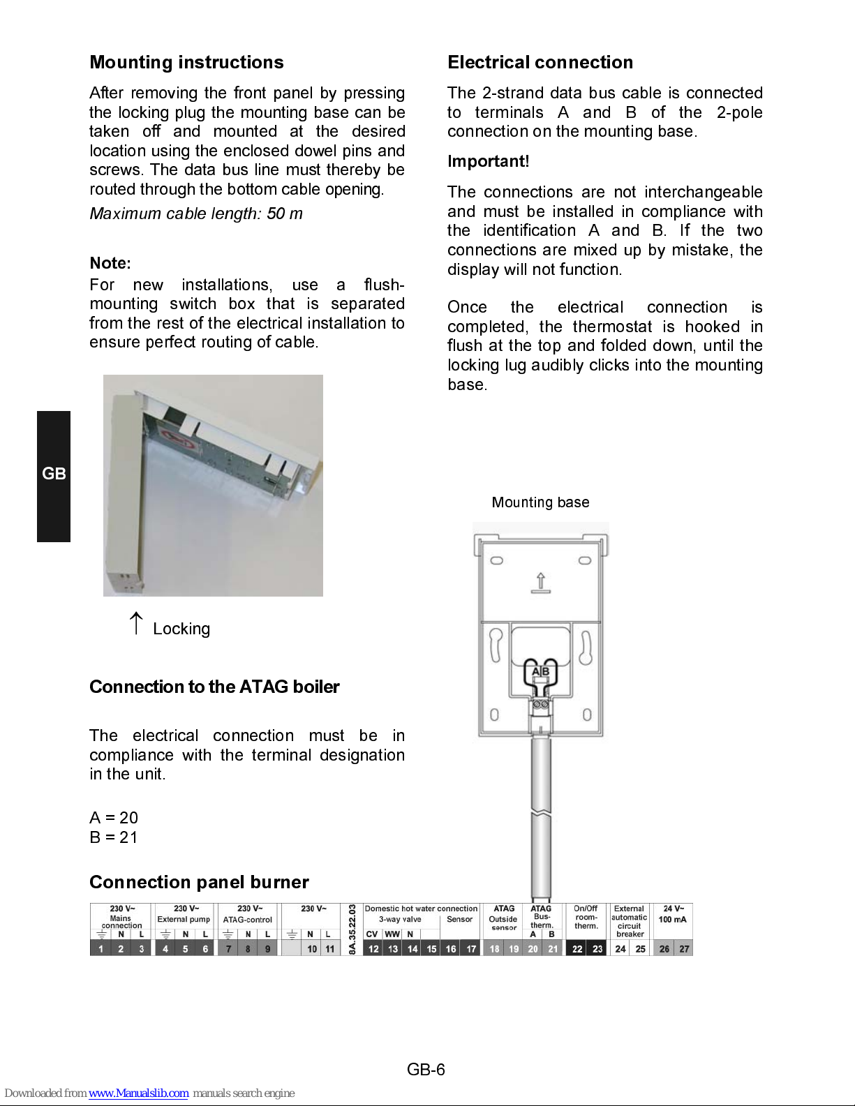
Mounting instructions
After removing the front panel by pressing
the locking plug the mounting base can be
taken off and mounted at the desired
location using the enclosed dowel pins and
screws. The data bus line must thereby be
routed through the bottom cable opening.
Maximum cable length: 50 m
Note:
For new installations, use a flush-
mounting switch box that is separated
from the rest of the electrical installation to
ensure perfect routing of cable.
Connection to the ATAG boiler
The electrical connection must be in
compliance with the terminal designation
in the unit.
A = 20
B = 21
Connection panel burner
Electrical connection
The 2-strand data bus cable is connected
to terminals A and B of the 2-pole
connection on the mounting base.
Important!
The connections are not interchangeable
and must be installed in compliance with
the identification A and B. If the two
connections are mixed up by mistake, the
display will not function.
Once the electrical connection is
completed, the thermostat is hooked in
flush at the top and folded down, until the
locking lug audibly clicks into the mounting
base.
↑
Locking
Mounting base
GB
Page 7
GB-7
Accessories
Outdoor sensor
Mounting Location
The outdoor sensor should be mounted on
the most exposed and coldest side of the
building (north or north-east) at a height of
min. 2 m above ground.
Exception:
If the preferred living area
is situated in a different
direction, you should
choose the respective
side of the building
accordingly.
When mounting the sensor mind external
heat sources (heated chimneys, warm hot
air from air shafts, installation on black
surfaces, thermal bridges in the wall, etc.)
which could falsify the measuring value.
The cable outlet must always be directed
downwards in order to avoid the
penetration of moisture.
The outside sensor may not be mounted
close to transmitting or receiving
equipment (on garage walls close to
receivers for radio-controlled garage door
openers, amateur radio antennas, radio
controlled alert systems or close to large
scale radio transmission equipment).
Electrical connection
For the electrical installation preferably
use a 2-strand cable with a minimum
cross-section of 0,6mm
2
. The connection
is made at the 2 screw terminals inside the
sensor case and may be interchanged.
Mounting instructions
1– Route the sensor cable to the
mounting location
2– Loosen lid screws from sensor case
and remove top
3– Mount sensor base with enclosed
central fastening screw.
Use sealing ring! The cable outlet must
be directed downwards!
4– Insert the sensor cable so that the
cable jacket is fully enclosed by the
sealing lip.
5– Establish the electrical connection.
The terminals may be interchanged.
6– Place the lid and screw it firmly onto
the base. Ensure correct fit of sealing
ring.
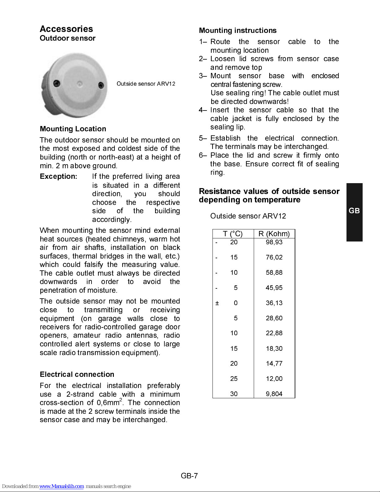
Resistance values of outside sensor
depending on temperature
Outside sensor ARV12
T (°C) R (Kohm)
- 20
- 15
- 10
- 5
± 0
5
10
15
20
25
30
98,93
76,02
58,88
45,95
36,13
28,60
22,88
18,30
14,77
12,00
9,804
Outside sensor ARV12
GB
Page 8
GB-8
Commissioning of the thermostat
Segment test and identification
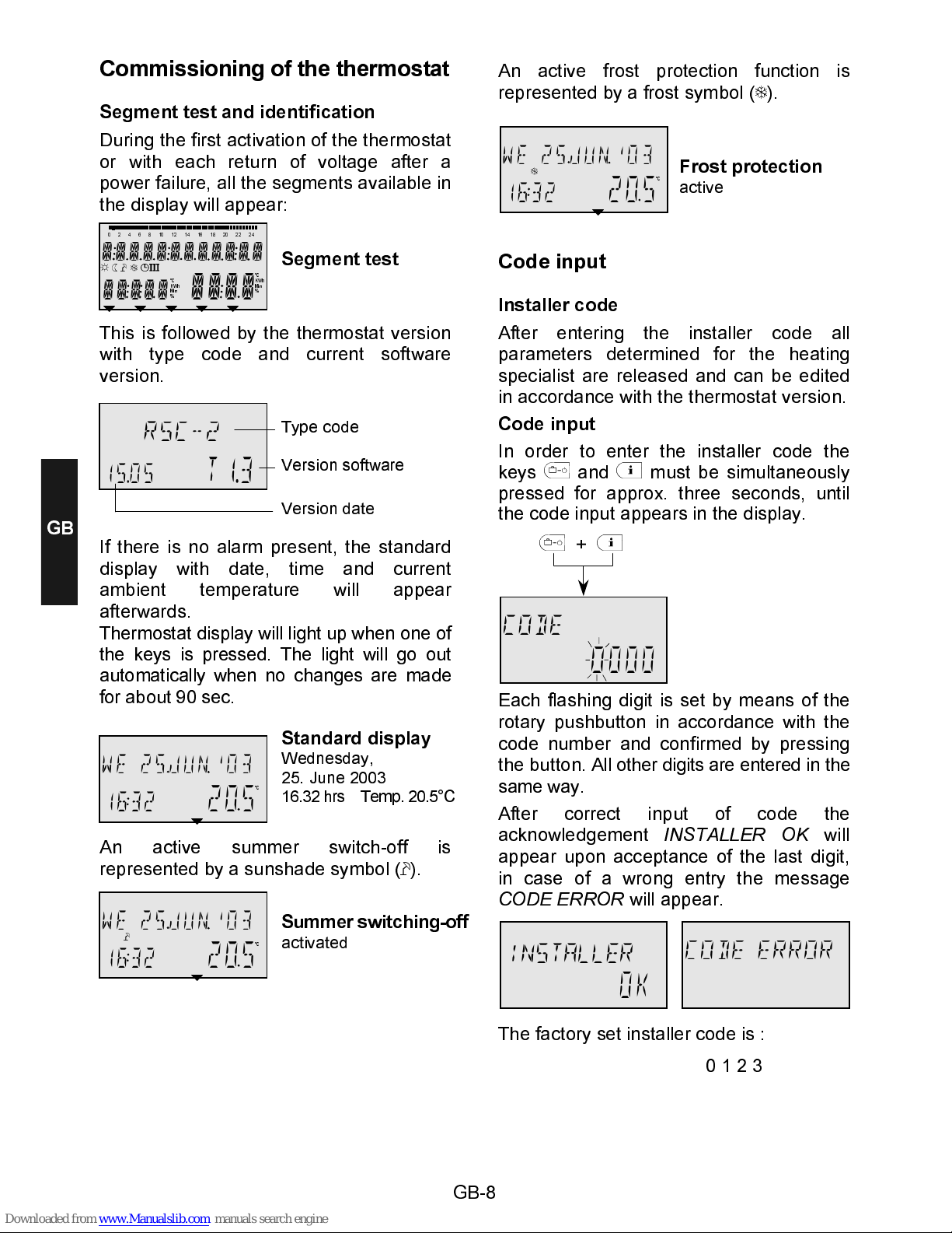
During the first activation of the thermostat
or with each return of voltage after a
power failure, all the segments available in
the display will appear:
This is followed by the thermostat version
with type code and current software
version.
If there is no alarm present, the standard
display with date, time and current
ambient temperature will appear
afterwards.
Thermostat display will light up when one of
the keys is pressed. The light will go out
automatically when no changes are made
for about 90 sec.
An active summer switch-off is
represented by a sunshade symbol (À).
An active frost protection function is
represented by a frost symbol (Á).
Code input
Installer code
After entering the installer code all
parameters determined for the heating
specialist are released and can be edited
in accordance with the thermostat version.
Code input
In order to enter the installer code the
keys
¢
and ¤ must be simultaneously
pressed for approx. three seconds, until
the code input appears in the display.
¢
+ ¤
Each flashing digit is set by means of the
rotary pushbutton in accordance with the
code number and confirmed by pressing
the button. All other digits are entered in the
same way.
After correct input of code the
acknowledgement
INSTALLER OK
will
appear upon acceptance of the last digit,
in case of a wrong entry the message
CODE ERROR
will appear.
The factory set installer code is :
¾ ¿ À Á Ä
°C
KWh
Min
%
°C
KWh
Min
%
0 2 4 6 8 10 12 14 16 18 20 22 24
fffff
ffff
R
-
15.05
T1.3
À
°C
;
1632
205
°C
;
1632
205
Segment test
Type code
Version software
Standard display
Wednesday,
25. June 2003
16.32 hrs Temp. 20.5°C
Summer switching-off
activated
Á
°C
;
1632
205
Frost protection
active
Version date
CODE
0
000
INSTALLER
OK
GB
0 1 2 3
Page 9
GB-9
Note:
If the code is not accepted
you should consult the
manufacturer!
Attention
: Enabled installer
parameters will be blocked
again if no further action
takes place over a period of
ten minutes. In this case the
installer code must be
entered again.
Alarm messages
In order to be able to perform an exact
diagnosis in case of a problem the control
system is equipped with a comprehensive
fault alarm system. Depending on the nature
of the fault a corresponding fault message will
appear in the display of the thermostat.
All fault messages are transmitted by the
MCBA and are d ivided into
A – permanent faults (permanent locking) with
MCBA error cod e E-XX
or
B – temporary faults (self-eliminating locking)
with MCBA error c ode B-XX
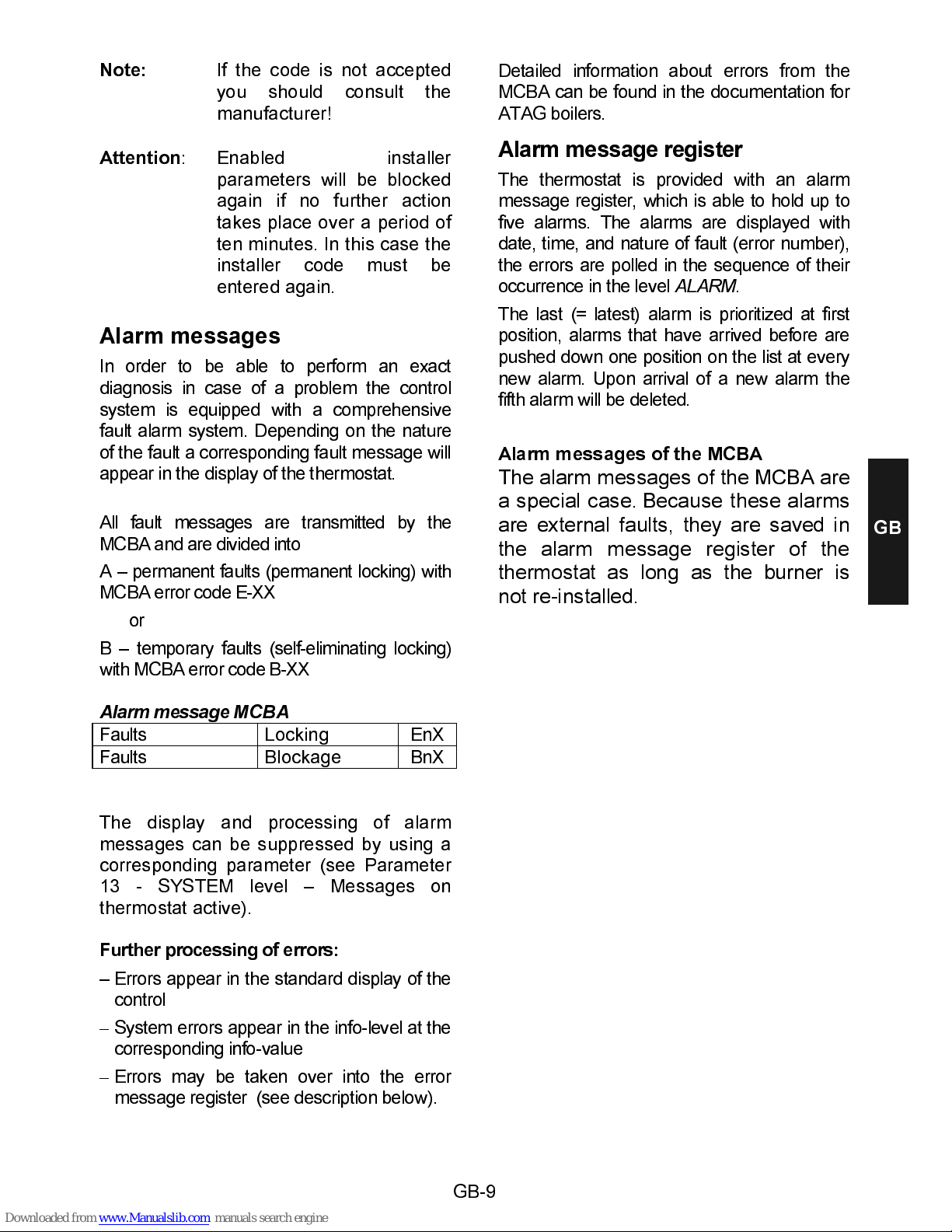
Alarm message MCBA
Faults Locking EnX
Faults Blockage BnX
The display and processing of alarm
messages can be suppressed by using a
corresponding parameter (see Parameter
13 - SYSTEM level – Messages on
thermostat active).
Further processing of errors:
– Errors appear in the standard display of the
control
–
System errors appear in the info-level at the
corresponding info-value
–
Errors may be taken over into the error
message register (see description below).
Detailed information about errors from the
MCBA can be found in the documentation for
ATAG boilers.
Alarm message register
The thermostat is provided with an alarm
message register, which is able to hold up to
five alarms. The alarms are displayed with
date, time, and nature of fault (error number),
the errors are polled in the sequence of their
occurrence in the level
ALARM
.
The last (= latest) alarm is prioritized at first
position, alarms that have arrived before are
pushed down one position on the list at every
new alarm. Upon arrival of a new alarm the
fifth alarm will be deleted.
Alarm messages of the MCBA
The alarm messages of the MCBA are
a special case.
Because these alarms
are external faults, they are saved in
the alarm message register of the
thermostat as long as the burner is
not re-installed.
GB
Page 10
GB-10
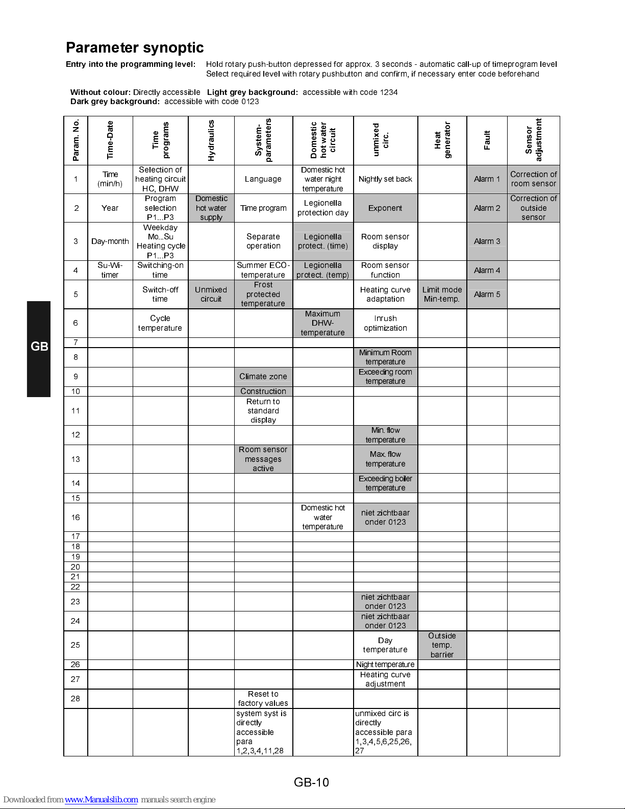
Parameter synoptic
Entry into the programming level:
Hold rotary push-button depressed for approx. 3 seconds - automatic call-up of timeprogram level
Select required level with rotary pushbutton and confirm, if necessary enter code beforehand
Without colour:
Directly accessible
Light grey background:
accessible with code 1234
Dark grey background:
accessible with code 0123
P
a
r
a
m
.
N
o
.
T
i
m
e
-
D
a
t
e
T
i
m
e
p
r
o
g
r
a
m
s
H
y
d
r
a
u
l
i
c
s
S
y
s
t
e
m
-
p
a
r
a
m
e
t
e
r
s
D
o
m
e
s
t
i
c
h
o
t
w
a
t
e
r
c
i
r
c
u
i
t
u
n
m
i
x
e
d
c
i
r
c
.
H
e
a
t
g
e
n
e
r
a
t
o
r
F
a
u
l
t
S
e
n
s
o
r
a
d
j
u
s
t
m
e
n
t
1
Time
(min/h)
Selection of
heating circuit
HC, DHW
Language
Domestic hot
water night
temperature
Nightly set back
Alarm 1
Correction of
room sensor
2 Year
Program
selection
P1...P3
Domestic
hot water
supply
Time program
Legionella
protection day
Exponent Alarm 2
Correction of
outside
sensor
3 Day-month
Weekday
Mo...Su
Heating cycle
P1...P3
Separate
operation
Legionella
protect. (time)
Room sensor
display
Alarm 3
4
Su-Wi-
timer
Switching-on
time
Summer ECO-
temperature
Legionella
protect. (temp)
Room sensor
function
Alarm 4
5
Switch-off
time
Unmixed
circuit
Frost
protected
temperature
Heating curve
adaptation
Limit mode
Min-temp.
Alarm 5
6
Cycle
temperature
Maximum
DHW-
temperature
Inrush
optimization
7
8
Minimum Room
temperature
9 Climate zone
Exceeding room
temperature
10 Construction
11
Return to
standard
display
12
Min. flow
temperature
13
Room sensor
messages
active
Max. flow
temperature
14
Exceeding boiler
temperature
15
16
Domestic hot
water
temperature
niet zichtbaar
onder 0123
17
18
19
20
21
22
23
niet zichtbaar
onder 0123
24
niet zichtbaar
onder 0123
25
Day
temperature
Outside
temp.
barrier
26 Night temperature
27
Heating curve
adjustment
28
Reset to
factory values
system syst is
directly
accessible
para
1,2,3,4,11,28
unmixed circ is
directly
accessible para
1,3,4,5,6,25,26,
27
GB
Page 11
GB-11
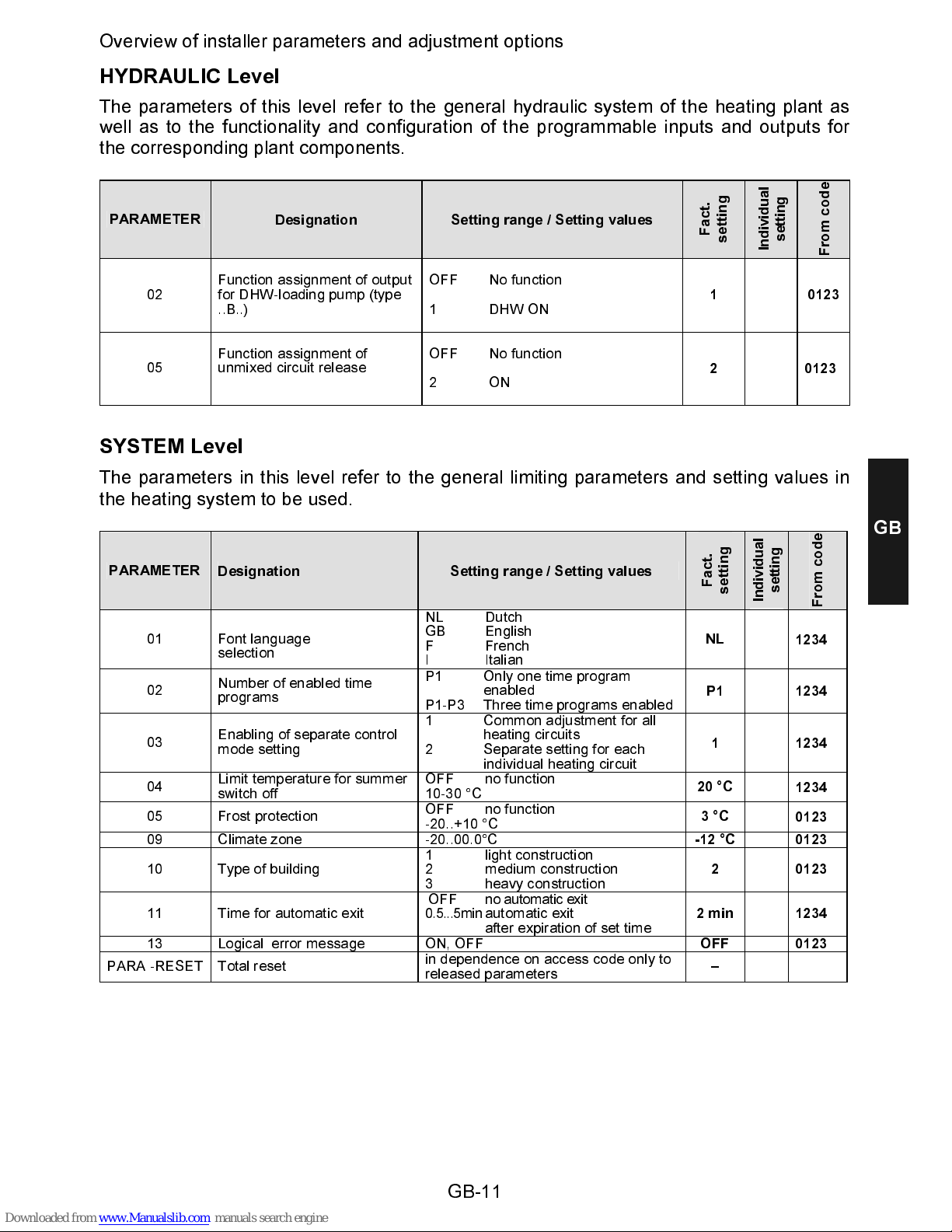
Overview of installer parameters and adjustment options
HYDRAULIC Level
The parameters of this level refer to the general hydraulic system of the heating plant as
well as to the functionality and configuration of the programmable inputs and outputs for
the corresponding plant components.
PARAMETER
Designation Setting range / Setting v alues
F
a
c
t
.
s
e
t
t
i
n
g
I
n
d
i
v
i
d
u
a
l
s
e
t
t
i
n
g
F
r
o
m
c
o
d
e
02
Function assignment of output
for DHW-loading pump (type
..B..)
OFF No function
1 DHW ON
1
0123
05
Function assignment of
unmixed circuit release
OFF No function
2 ON
2
0123
SYSTEM Level
The parameters in this level refer to the general limiting parameters and setting values in
the heating system to be used.
PARAMETER
Designation Setting range / Setting v alues
F
a
c
t
.
s
e
t
t
i
n
g
I
n
d
i
v
i
d
u
a
l
s
e
t
t
i
n
g
F
r
o
m
c
o
d
e
01
Font language
selection
NL Dutch
GB English
F French
I Italian
NL
1234
02
Number of enabled time
programs
P1 Only one time program
enabled
P1-P3 Three time programs enabled
P1
1234
03
Enabling of separate control
mode setting
1 Common adjustment for all
heating circuits
2 Separate setting for each
individual heating circuit
1
1234
04
Limit temperature for summer
switch off
OFF no function
10-30 °C
20 °C
1234
05 Frost protection
OFF no function
-20..+10 °C
3 °C
0123
09 Climate zone -20..00.0°C
-12 °C
0123
10 Type of building
1 light construction
2 medium construction
3 heavy construction
2
0123
11 Time for automatic exit
OFF no automatic exit
0.5...5min automatic exit
after expira tion of set time
2 min
1234
13 Logical error message ON, OFF
OFF
0123
PARA -RESET Total reset
in dependence on access code only to
released parameters
–
GB
Page 12
GB-12
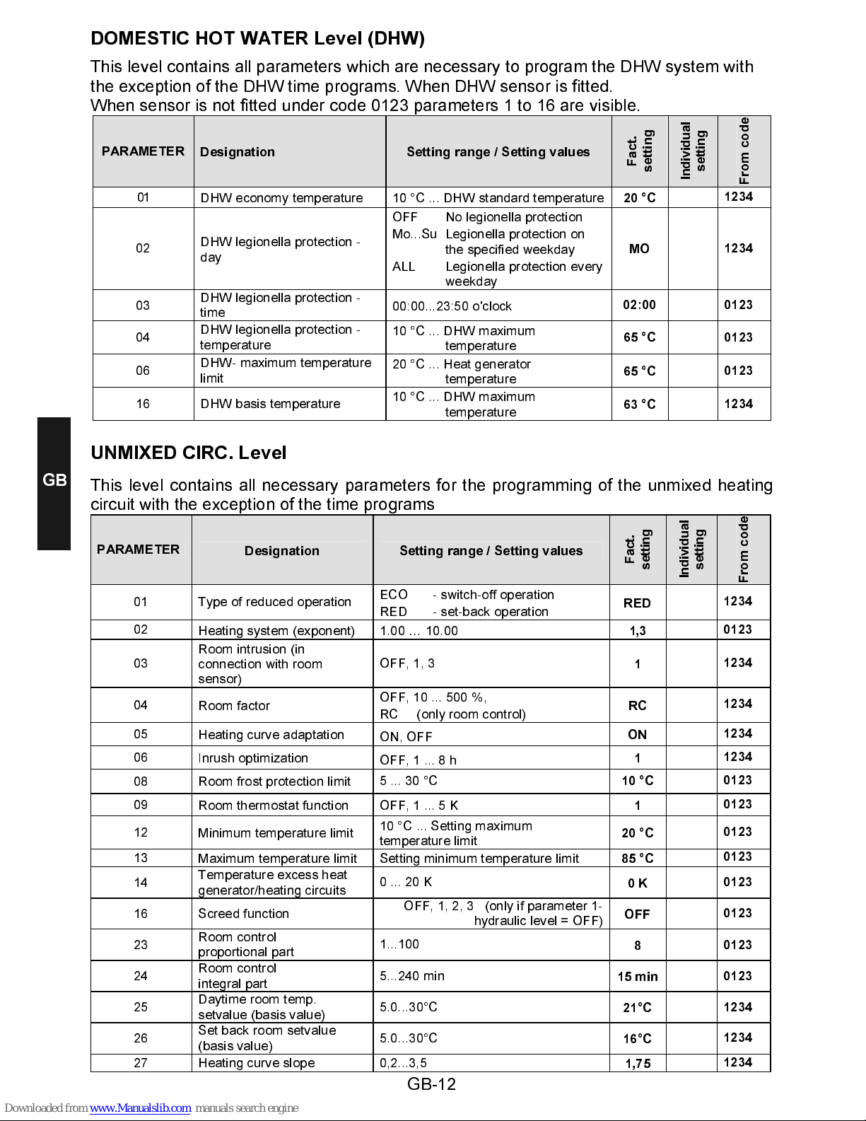
DOMESTIC HOT WATER Level (DHW)
This level contains all parameters which are necessary to program the DHW system with
the exception of the DHW time programs. When DHW sensor is fitted.
When sensor is not fitted under code 0123 parameters 1 to 16 are visible.
PARAMETER
Designation Setting range / Setting values
F
a
c
t
.
s
e
t
t
i
n
g
I
n
d
i
v
i
d
u
a
l
s
e
t
t
i
n
g
F
r
o
m
c
o
d
e
01
DHW economy temperature 10 °C ... DHW standard temperature
20 °C
1234
02
DHW legionella protection -
day
OFF No legionella protection
Mo...Su Legionella protection on
the specified weekday
ALL Legionella protection every
weekday
MO
1234
03
DHW legionella protection -
time
00:00...23:50 o'clock
02:00
0123
04
DHW legionella protection -
temperature
10 °C ... DHW maximum
temperature
65 °C
0123
06
DHW- maximum temperature
limit
20 °C ... Heat generator
temperature
65 °C
0123
16 DHW basis temperature
10 °C ... DHW maximum
temperature
63 °C
1234
UNMIXED CIRC. Level
This level contains all necessary parameters for the programming of the unmixed heating
circuit with the exception of the time programs
PARAMETER
Designation Setting range / Setting values
F
a
c
t
.
s
e
t
t
i
n
g
I
n
d
i
v
i
d
u
a
l
s
e
t
t
i
n
g
F
r
o
m
c
o
d
e
01
Type of reduced operation
ECO - switch-off operation
RED - set-back operation
RED
1234
02
Heating system (exponent)
1.00 … 10.00
1,3
0123
03
Room intrusion (in
connection with room
sensor)
OFF, 1, 3
1
1234
04
Room factor
OFF, 10 ... 500 %,
RC (only room control)
RC
1234
05
Heating curve adaptation
ON, OFF
ON
1234
06
Inrush optimization
OFF, 1 ... 8 h
1
1234
08 Room frost protection limit
5 ... 30 °C
10 °C
0123
09
Room thermostat function OFF, 1 ... 5 K
1
0123
12
Minimum temperature limit
10 °C ... Setting maximum
temperature limit
20 °C
0123
13
Maximum temperature limit Setting minimum temperature limit
85 °C
0123
14
Temperature excess heat
generator/heating circuits
0 ... 20 K
0 K
0123
16 Screed function
OFF, 1, 2, 3 (only if parameter 1-
hydraulic level = OFF)
OFF
0123
23
Room control
proportional part
1...100
8
0123
24
Room control
integral part
5...240 min
15 min
0123
25
Daytime room temp.
setvalue (basis value)
5.0...30°C
21°C
1234
26
Set back room setvalue
(basis value)
5.0...30°C
16°C
1234
27 Heating curve slope
0,2...3,5
1,75
1234
GB
Page 13
GB-13
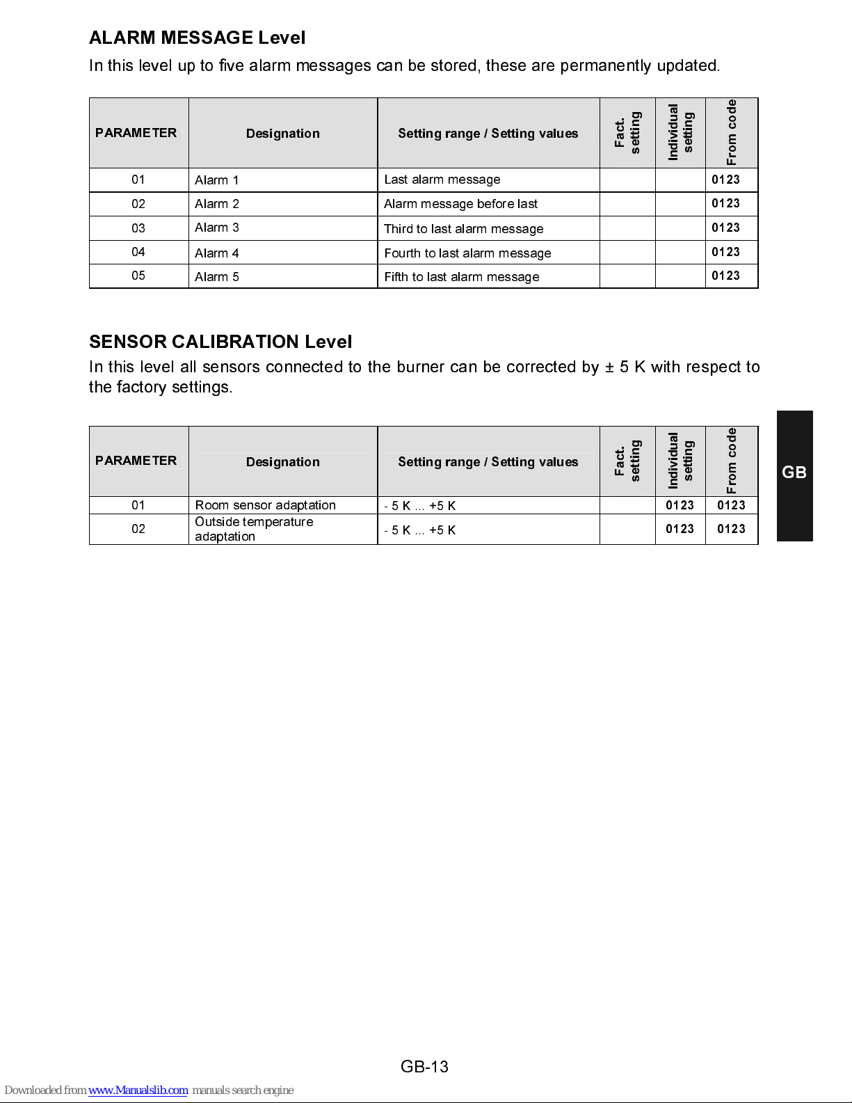
ALARM MESS A G E Level
In this level up to five alarm messages can be stored, these are permanently updated.
PARAMETER
Designation Setting rang e / Setting v alues
F
a
c
t
.
s
e
t
t
i
n
g
I
n
d
i
v
i
d
u
a
l
s
e
t
t
i
n
g
F
r
o
m
c
o
d
e
01
Alarm 1
Last alarm message
0123
02 Alarm 2 Alarm message before last
0123
03
Alarm 3
Third to last alarm message
0123
04
Alarm 4 Fourth to last alarm message
0123
05
Alarm 5 Fifth to last alarm message
0123
SENSOR CALIBRATION Level
In this level all sensors connected to the burner can be corrected by ± 5 K with respect to
the factory settings.
PARAMETER
Designation Setting rang e / Setting v alues
F
a
c
t
.
s
e
t
t
i
n
g
I
n
d
i
v
i
d
u
a
l
s
e
t
t
i
n
g
F
r
o
m
c
o
d
e
01 Room sensor adaptation
- 5 K ... +5 K
0123 0123
02
Outside temperature
adaptation
- 5 K ... +5 K
0123 0123
GB
Page 14

GB-14
Notes
GB
Page 15

Page 16

ATAG Verwarming Nederland BV
Postbus105
7130 AC Lichtenvoorde
T: 0544 - 391777
F: 0544 - 391703
[email protected]
www.atagverwarming.nl
Strebel Ltd.
1F, Albany park industrial estate
Frimley road, Camberley
Surrey GU16 7BP
Telephone: (01276) 685422
Fax: (01276) 685405
[email protected]
www.strebel.co.uk
Met deze vernieuwde uitgave vervallen alle voorgaande installatievoorschriften.
This renewed publication cancels all previous installation instructions.
Wijzigingen voorbehouden • We reserve the right to make changes
Art. 0451003400 - 0445-20
 Loading...