


QuickAmp Manual
User Manual
for the
136-channel physiological measure ment system
QuickAmp-136
0044
Version 2.3
02-2012
TMS code: 92-0122-000-0-3
QuickAmp-136_v2.3.doc

Contents
1 About this manual 3
2 Product description / intended use 3
3 Warnings and precauti onary measures 3
4 Installation 5
5 Operating instructions 6
6 Technical background 8
Appendix 1 Specifications
Appendix 2 Channel overview
Appendix 3 Connector pinout
QuickAmp Manual
2

QuickAmp Manual
1 About this manual
This manual, which is intended for the user of the QuickAmp, contains general operating instructions, precautionary
measures, maintenance instructions and information about components. To maximize the safety, service life and
efficiency of the system, it is important that you read this manual through carefully and familiarize yourself with the
various controls and accessories before starting to use the system.
2 Product description / intended use
The QuickAmp 136 is a 136-channel stationary system for physiological research.
The system has 128 unipolar electrophysiological (‘ExG’) inputs, 4 bipolar electrophysiological (‘BIP’) inputs, 4 so
called auxiliary (‘AUX’) inputs and one digital input-channel (8 bits).
The unipolar electrophysiological inputs are configured as a reference amplifier: all channels are amplified against
the average of all connected inputs. With these channels or the Bipolar channels signals like EEG, EMG, ECG,
EOG, EGG etc. can be measured.
The auxiliary inputs can be used for measuring temperature, pH, respiration, oxygen saturation etc. Each AUX
channel has a +5V and –5V output in order to use active sensors or sensor modules.
An external power s upply, which plugs into the mains socket, powers the Q uickAmp. The QuickAmp is connected to
a PC by means of bidirectional glass fiber. Inside the PC a special interface board (DSP/fiber card) or a USB
interface takes care of the glass fiber communication. The QuickAmp is in this situation completely controlled by the
PC.
The system does not perform any signal interpretation or signal analysis. This is left to the researcher/Physician.
The system is NOT intended for use in a life supporting system.
indications for use
The QuickAmp Amplifier family is intended to be used by or under the direction of a p hysician for acquisition of
EEG, polygra phy and polysomnography signals and transmission of the signals to a PC d uring recording of neurophysical/ physiological research and exams.
Polygraphy and Polysomnography may besides EEG, include physiological information such as EMG, ECG, EOG,
EGG, PH, Respiration, Temperature and Oxygen Saturation.
3 Warnings and precautionary measures
This section contains general warnings and precautionary measures that are important for the safe use of the system.
: manual contains important safety information
: class II
: type CF
3

QuickAmp Manual
Instructions for Disposal of Waste Electrical and Electronic Equipment (WEEE) by Users in the European Union
This symbol is placed on the product, which indicates that this product must not be disposed of with other
waste. Instead, it is the user’s responsibility to dispose of their waste equipment by handing it over to a
designated collection point for the recycling of waste electrical and electronic equipment. The separate
collection and recycling of your waste equipment at the time of disposal will help to conserve natural
resources and ensure that it is recycled in a manner that protects human health and the environment. For
more information about where you can drop off your waste equipment for recycling, please contact your
local city office, your household waste disposal service, or TMS International BV.
• Under federal law (only applicable to the USA) this apparatus may only be sold by or on the order of a
physician or licensed practicioner.
The appa ratus may only be used under t he constant supervision of or on the i ns tructions of a physici an or other
authorized medical professional.
• The only external power supply that may be used is the original supply, that came with the QuickAmp. DO
NOT replace it with something else. If any non-TMSI type of supply is used then patient safety is not
guaranteed.
• Make sure that the wall socket is well earthed, to reduce 50 or 60Hz disturbances
• Do not combine the use of the QuickAmp with any other electronic device, except those specified in this
manual.
• Sensors with their own power are not to be connected to the AUX inputs.
• This system is not suitable for use in an inflammable mixture of anesthetics and air, oxygen or nitrous oxide.
• Do not expose the system to direct sunlight, heat from a source of thermal radiation, excessive amounts of dust,
moisture, vibrations, or mechanical shocks.
• Not to be immersed in any liquid
• If any liquids or moisture penetrate the system or any part thereof, remove the plug from the wall socket and
have the system checked by an approved technician.
• The QuickAmp must not be connected to a patient undergoing Electro surgery.
• The QuickAmp must not be connected to a patient undergoing MRI.
• The QuickAmp is not defibrillation proof only in combination with special patient cables. Contact TMSi for
more details.
• The system is intended to allow direct diagnosis or monitoring of vital physiological processes. It is not
specifically intended for monitoring of vital physiological parameters, where the nature of variations is such
that it could result in immediate danger to the patient. (MDD Annex IX, rule 10).
• This system is not suitable for sterilization.
• Disposable electrodes which are used for electrophysiological measurements may be a biohazard. Handle, and
when applicable dispose of these materials in accordance with accepted medical practice and any applicable
local, state and federal laws and regulations.
• Reusable electrodes present a potential risk of cross-infection especially when used on abraded skin, unless
they are restricted to a single patient or sterilized between patients. When sterilizing electr odes, employ only
gas sterilization.
• Store electrodes within separate bag within the packaging to prevent contamination
• Take care in arranging patient and sensor cables to avoid risk of patient entanglement or strangulation
• Make sure the PC is installed according to local regulations and safety precautions.
• Do not use an operating cellular p hone within 30 cm of the QuickAmp to avoid excessive noise on the signals
• Sharp bends or winding the cables in a loop smaller than 5 cm may damage the cables
• Do not bend the glass fiber too sharply, as it may break.
• The QuickAmp contains recyclable materials that can be harmful for the environment. Specialized companies
can separate these materials when the system is disassembled. Before disposing of the apparatus, enquire about
the local waste management regulations.
• Cleaning of the QuickAmp can be done with a slightly damp soft cloth. Before cleaning, make sure the
QuickAmp is turned off. Never use any aggressive chemicals to clean the QuickAmp.
• Due to design no calibrations are needed.
• There are no known side effects from the use of this equipment.
4

QuickAmp Manual
4 Installation
Install the fiber interface (Fusbi) by placing the hardware and use the drivers software as supplied on the separate
CD.
Find a well grounded mains socket for the external power supply, and connect the power connector to the back of
the QuickAmp.
Connect the bidirectional fiber to both the installed interface card and the back of the QuickAmp. A good
connection is indicated by a little ‘click’.
Turn the QuickAmp on with the switch on the back. The POWER ind ication should li ght up. When this is the first
time on the PC the PC will ask for the driver software which can be found on the same CD as needed for the fiber
interface. The front-end is now ready for use.
5
3
2
1
5
6
4
7
8
9
QuickAmp Manual
5 Operating instructions
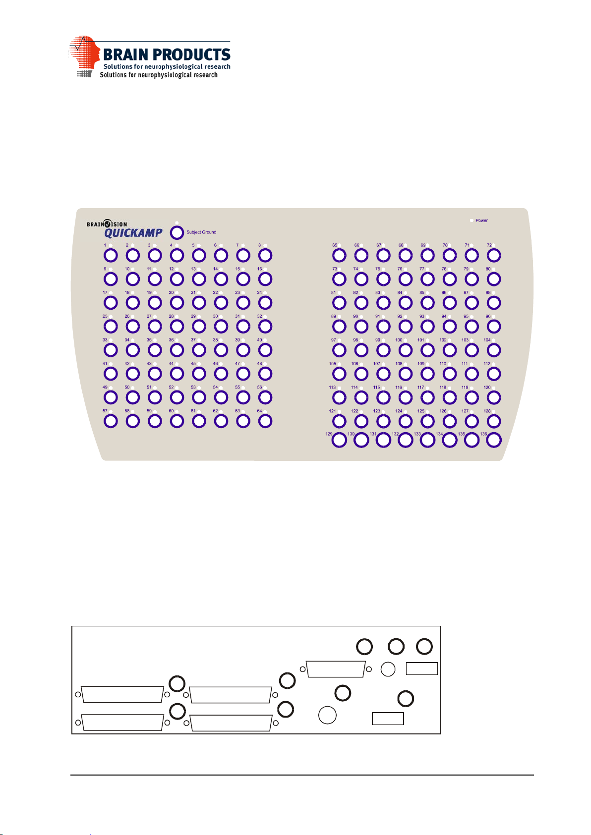
The front panel of the QuickAmp 136 has the following items:
Power Power on indicator (green LED)
1..128 128 EEG / electrophysiological input connectors and bad impedance LED
129..132 4 Bipolar electrophysiological input connectors
133..136 4 Auxiliary channel input connectors
Subject Ground Subject Ground connection for electrophysiological measurements
QuickAmp-136 front view
On the back panel, the follo wing items can be identified:
1 Connector for external power supply
2 Fiber connector
3 BNC connector for digital input
4 DB25 connector for digital input
5 DB37 first headcap connector, Channel 1 - 32
6 DB37 second headcap connector, Channel 33 - 64
7 DB37 third headcap connector, Channel 65 - 96
8 DB37 fourth headcap connector, Channel 97 - 128
9 On/Off switch
QuickAmp back panel
6
QuickAmp Manual
Using Subject electrode leads
For unipolar (‘reference amplifier’) signals: use 2 or more unipolar shielded cables with snap connector or fixed
Ag/AgCl electrode cup (micro-coax inputs).
For bipolar signals: use 1 or more bipolar cables (4-pin bipolar inputs).
The numbers placed near the connector correspond to the QuickAmp output channels.
For a good measuring, make sure the electrodes make a good contact with the subject. Ag/AgCl electrodes are
recommended, because of their excellent signal quality and stability.
Subject ground
Always use one unipolar shielded cable (snap connector or fixed Ag/AgCl electrode cup) for subject ground (GND
connection).
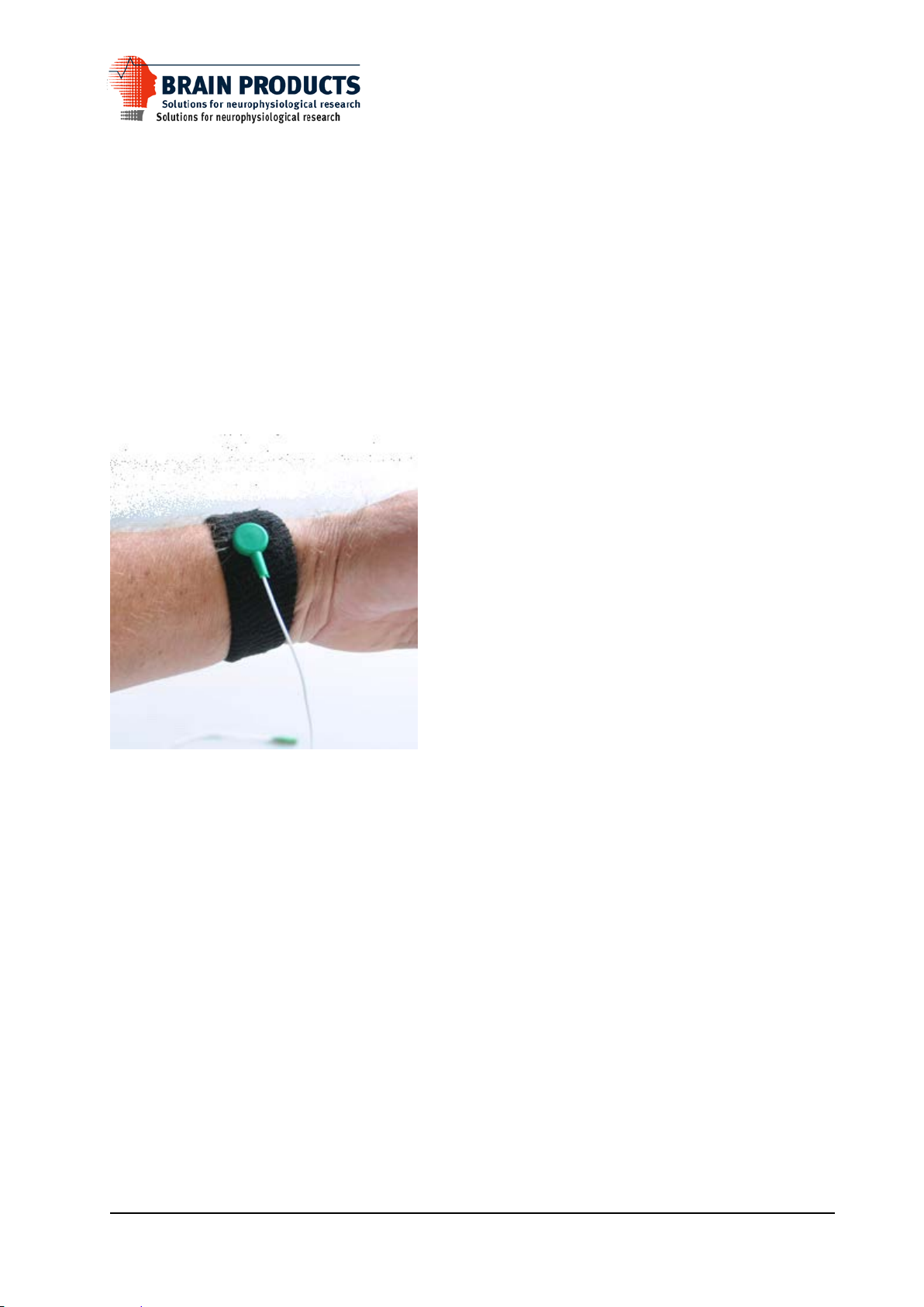
It is very important, that the impedance of the subject ground is kept low, if possible below 5kOhm. To guarantee
that the impedance of the subject ground has low impedance several measures can be taken, like cleaning the skin or
adding a lot of gel. We recommend a special electrode, the wrist belt electrode. This electrode is shown in the figure
below. The electrode is saturated with water, and fastened on the wrist.
Using Auxiliary sensors
Connect the auxiliary sensor (e.g. 3D-accelerometer) to one (or more, if required) of the 5-pin auxiliary inputs. The
numbers placed near the connector correspond to the QuickAmp output channels.
7

QuickAmp Manual
6 Technical background
In the QuickAmp-system the following items can be identified:
Subject Ground connector
electrophysiological (ExG) and (BIP) input connectors
headcap connectors
auxiliary (AUX) input connectors
ExG impedance measurement
ExG calibration
digital input
external power supply connection
bi-directional glass fiber
Subject Ground connector
The Subject Ground electrode is meant as a way to keep subject potential and QuickAmp amplifier potential at about
the same level. It is not an active input. For good disturbance-free measurements make sure that the subject ground
electrode has low impedance.
Electrophysiological (ExG) and (BIP) input connector s
The ExG input s on the front of the Qui ckAmp are used to perform ExG (EEG, ECG, EOG, etc) measurements. All
electrode cables are individual shielded (active shield). This ensures a disturbance free measurement. 50 Hz mains
interference and cable movement artefacts are reduced to a minimum.
Inputs that are not connected to an electrode cable are automatically switched off.
It is advisable to use only one type of electrodes (e.g. Ag/AgCl, Sintered chloride, Gold, tin) at a time, including the
subject ground electrode. Different metals will cause large electrode offset differences, which might overflow the
amplifiers.
Headcap connectors
The headcap connectors (situated at the back side of the box) are another way to connect the subject to the front-end.
The inputs are connected directly to the accompanying unipolar ExG input. The active shielding signals are not
present on the headcap connectors. Appendix 3 shows the list of pin numbers of the connectors.
Auxiliary (AUX) input connectors
The auxiliary inputs can be used to connect active sensors like SaO2 sensors, 3D-accelerometer, respiration bands,
nasal flow sensors, pH sensor s etc.
Each auxiliary input has a 5-pin connec t or. Signals on this connector are +5V output, -5V output, GND, +signal
input and -signal input.
An unconnected input will automatically be switched off (i.e. will show a zero signal).
In Appendix 3 the pin-out of the AUX connector is given.
ExG impedance measurement
The QuickAmp contains a circuit to perform ExG electrode impedance measurements.
The impedance measurement can be started with the PC. The PC-controlled impedance measurement starts by
sending the front-end an impedance measurement command and an impedance threshold value. Like in the manual
mode, all channels that have an impedance higher than the threshold value will have their LEDs turned on.
At power-up of the QuickAmp system all LED’s will be turned on for about 1 second.
8

QuickAmp Manual
ExG calibration
The PC can put the front-end in calibration mode in order to test the ExG amplifiers. This mode is indicated by a
blinking impedance LED. Select the calibration mode only if no subject is connected to the input. Otherwise the
subjects EEG will interfere with the calibration signals.
Digital input
On the backside of the system a DB25 connector and a BNC connector are available to be used as a digital input (8
bits DB25 and 1 bit BNC). On this input one c an connect e.g. the sync-output of a stimulator in order to trigger on
certain events. The inputs are electrically isolated from the rest of the system by means of optocouplers.
External power supply
To get the best signal quality (minimum 50 Hz interference) make sure that a well grounded mains outlet is used.
The external power supply guarantees patient safety during all circumstances. Do NEVER use a power supply other
than the one that came with the front-end.
A switch on the back of t he External power supply turns the system on or off.
Bi-directional glass fiber
The glass fiber interface takes care of the bi-directional communication between Quic kAmp a nd PC. Through this
link the PC can set the sample frequency of the QuickAmp, control the measurement mode (normal, impedance,
calibration) etc. The signal data from the ADCs is sent from the QuickAmp to the PC over the fiber in high speed
and at high resolution.
9

QuickAmp Manual
Appendix 1 Specifications
Type QuickAmp-136
Classification
according to MDD Class IIa
0044 CE-certified
Dimensions
External dimensions 210 x 360 x 92 mm (l x w x h)
External power supply:
Input 110-240V AC, 50 - 60 Hz
Output voltage 10V DC
Output current max. 700 mA
Isolation voltage > 4000V
Leakage current < 3 µA
safety a ccor ding to IEC 60601-1 class II type CF
Unipolar ExG inputs (EEG, ECG, EOG, EMG etc):
Number 128
Noise < 1.0 µVrms (@ lowest sample rate)
Gain 26,55 x
Input signal difference < 0.15 V
Input common mode range -2V - +2V
Input impedance > 10
CMRR 100 dB (typical), m in imal 90 dB
Connector micro coax, active shielding // subD37 fem ale con n ector
Bipolar ExG inputs (ECG, EOG, EMG etc):
Number 4
Noise < 1.0 µVrms (@ lowest sample rate)
Gain 26,55 x
Input signal difference < 0.15 V
Input common mode range -2V - +2V
Input impedance > 10
CMRR 100 dB (typical), m in imal 90 dB
Connector 4 pin BINDER, active shielding
AUX inputs:
Number 4
Noise < 20 µVrms (@ low es t s ample rate)
Gain 1 x
Input signal range (diff) -3V -+3V
Input common mode range -4V - +4V
Input impedance > 10
CMRR 80 dB (typical), minimal 70 dB
Output voltage +5V, -5V, max 5m A per channel, or 20mA for all chan n els toget h er
Connector 5 pin BINDER
Digital input
Connector DB25, 8 signal , 1 c ommon grou n d (bi t 0 al s o by BNC)
Input turn-on current = 2 mA @ Vin = 3.0V, Vin_max = 5V
Isolation > 4000 V, by mea n s of optocoupler (H11L1)
10
12
Ω
12
Ω
12
Ω

QuickAmp Manual
Sampling:
Number of channels 136 channels simultaneously
Resolution 24 bits, ExG//BIP 18.39 n V per bi t , AUX 0.48828 µV per bi t
Sample frequency 2000 Hz, 1000 Hz, 500 Hz, 250 Hz, 125 Hz
Output 138 channels: 1-128=U n i pol ar Ex G
129-132 = Bipolar ExG
133-136 = AUX
137=Digital (bit 0-7=digital trigger input (inverted))
138=Digital (bit 0-14=sawtooth test signal)
Filtering/gain:
Gain ExG 26.55 x, fixed (= 37,7 mV/V),
BIP 26.55 x, fixed (= 37,7 mV/V),
AUX 1 x, fixed (= 1 V/V)
Highpass none
Lowpass digital FIR filter, cutoff frequency = guaran teed 0.2 * s ample frequency.
This means that the -3dB point is higher than 0.2 * sample frequency
Fiber communication:
Bit rate 7.68 Mbit/s
Max supported sample rate 2000 Hz
Fiber length up to 70m
Required interface FUSBI, USB2.0 port on PC
Storage and transportation conditions:
temperature -10ºC - +50ºC
humidity 10% - 100%
pressure 500 hPa - 1060 hPa
Usage conditions:
temperature 0ºC - +40ºC
humidity 10% - 90%
pressure 500 hPa - 1060 hPa
Manufactured by:
TMS International
Zutphenstraat 57
7575 EJ Oldenzaal
P.O. Box 6044
7503 GA Ensche de
The Netherlands
www.tmsi.com
support@tmsi.com
tel +31-541-534603
fax +31-541-534628
Technical changes reserved
11

nr
name
function
resolution
range
1
ExG1
Unipolar input 1
0.01839 µV
-150mV / +150mV
2
ExG2
Unipolar input 2
0.01839 µV
-150mV / +150mV
3
ExG3
Unipolar input 3
0.01839 µV
-150mV / +150mV
4
ExG4
Unipolar input 4
0.01839 µV
-150mV / +150mV
5
ExG5
Unipolar input 5
0.01839 µV
-150mV / +150mV
6
ExG6
Unipolar input 6
0.01839 µV
-150mV / +150mV
7
ExG7
Unipolar input 7
0.01839 µV
-150mV / +150mV
8
ExG8
Unipolar input 8
0.01839 µV
-150mV / +150mV
9
ExG9
Unipolar input 9
0.01839 µV
-150mV / +150mV
10
ExG10
Unipolar input 10
0.01839 µV
-150mV / +150mV
11
ExG11
Unipolar input 11
0.01839 µV
-150mV / +150mV
12
ExG12
Unipolar input 12
0.01839 µV
-150mV / +150mV
13
ExG13
Unipolar input 13
0.01839 µV
-150mV / +150mV
14
ExG14
Unipolar input 14
0.01839 µV
-150mV / +150mV
15
ExG15
Unipolar input 15
0.01839 µV
-150mV / +150mV
16
ExG16
Unipolar input 16
0.01839 µV
-150mV / +150mV
17
ExG17
Unipolar input 17
0.01839 µV
-150mV / +150mV
18
ExG18
Unipolar input 18
0.01839 µV
-150mV / +150mV
19
ExG19
Unipolar input 19
0.01839 µV
-150mV / +150mV
20
ExG20
Unipolar input 20
0.01839 µV
-150mV / +150mV
21
ExG21
Unipolar input 21
0.01839 µV
-150mV / +150mV
22
ExG22
Unipolar input 22
0.01839 µV
-150mV / +150mV
23
ExG23
Unipolar input 23
0.01839 µV
-150mV / +150mV
24
ExG24
Unipolar input 24
0.01839 µV
-150mV / +150mV
25
ExG25
Unipolar input 25
0.01839 µV
-150mV / +150mV
26
ExG26
Unipolar input 26
0.01839 µV
-150mV / +150mV
27
ExG27
Unipolar input 27
0.01839 µV
-150mV / +150mV
28
ExG28
Unipolar input 28
0.01839 µV
-150mV / +150mV
29
ExG29
Unipolar input 29
0.01839 µV
-150mV / +150mV
30
ExG30
Unipolar input 30
0.01839 µV
-150mV / +150mV
31
ExG31
Unipolar input 31
0.01839 µV
-150mV / +150mV
32
ExG32
Unipolar input 32
0.01839 µV
-150mV / +150mV
33
ExG33
Unipolar input 33
0.01839 µV
-150mV / +150mV
34
ExG34
Unipolar input 34
0.01839 µV
-150mV / +150mV
35
ExG35
Unipolar input 35
0.01839 µV
-150mV / +150mV
36
ExG36
Unipolar input 36
0.01839 µV
-150mV / +150mV
37
ExG37
Unipolar input 37
0.01839 µV
-150mV / +150mV
38
ExG38
Unipolar input 38
0.01839 µV
-150mV / +150mV
39
ExG39
Unipolar input 39
0.01839 µV
-150mV / +150mV
40
ExG40
Unipolar input 40
0.01839 µV
-150mV / +150mV
41
ExG41
Unipolar input 41
0.01839 µV
-150mV / +150mV
42
ExG42
Unipolar input 42
0.01839 µV
-150mV / +150mV
43
ExG43
Unipolar input 43
0.01839 µV
-150mV / +150mV
44
ExG44
Unipolar input 44
0.01839 µV
-150mV / +150mV
45
ExG45
Unipolar input 45
0.01839 µV
-150mV / +150mV
46
ExG46
Unipolar input 46
0.01839 µV
-150mV / +150mV
47
ExG47
Unipolar input 47
0.01839 µV
-150mV / +150mV
48
ExG48
Unipolar input 48
0.01839 µV
-150mV / +150mV
49
ExG49
Unipolar input 49
0.01839 µV
-150mV / +150mV
50
ExG50
Unipolar input 50
0.01839 µV
-150mV / +150mV
51
ExG51
Unipolar input 51
0.01839 µV
-150mV / +150mV
52
ExG52
Unipolar input 52
0.01839 µV
-150mV / +150mV
Appendix 2 Channel overview
Channel list QuickAmp-136:
QuickAmp Manual
12

53
ExG53
Unipolar input 53
0.01839 µV
-150mV / +150mV
54
ExG54
Unipolar input 54
0.01839 µV
-150mV / +150mV
55
ExG55
Unipolar input 55
0.01839 µV
-150mV / +150mV
56
ExG56
Unipolar input 56
0.01839 µV
-150mV / +150mV
57
ExG57
Unipolar input 57
0.01839 µV
-150mV / +150mV
58
ExG58
Unipolar input 58
0.01839 µV
-150mV / +150mV
59
ExG59
Unipolar input 59
0.01839 µV
-150mV / +150mV
60
ExG60
Unipolar input 60
0.01839 µV
-150mV / +150mV
61
ExG61
Unipolar input 61
0.01839 µV
-150mV / +150mV
62
ExG62
Unipolar input 62
0.01839 µV
-150mV / +150mV
63
ExG63
Unipolar input 63
0.01839 µV
-150mV / +150mV
64
ExG64
Unipolar input 64
0.01839 µV
-150mV / +150mV
65
ExG65
Unipolar input 65
0.01839 µV
-150mV / +150mV
66
ExG66
Unipolar input 66
0.01839 µV
-150mV / +150mV
67
ExG67
Unipolar input 67
0.01839 µV
-150mV / +150mV
68
ExG68
Unipolar input 68
0.01839 µV
-150mV / +150mV
69
ExG69
Unipolar input 69
0.01839 µV
-150mV / +150mV
70
ExG70
Unipolar input 70
0.01839 µV
-150mV / +150mV
71
ExG71
Unipolar input 71
0.01839 µV
-150mV / +150mV
72
ExG72
Unipolar input 72
0.01839 µV
-150mV / +150mV
73
ExG73
Unipolar input 73
0.01839 µV
-150mV / +150mV
74
ExG74
Unipolar input 74
0.01839 µV
-150mV / +150mV
75
ExG75
Unipolar input 75
0.01839 µV
-150mV / +150mV
76
ExG76
Unipolar input 76
0.01839 µV
-150mV / +150mV
77
ExG77
Unipolar input 77
0.01839 µV
-150mV / +150mV
78
ExG78
Unipolar input 78
0.01839 µV
-150mV / +150mV
79
ExG79
Unipolar input 79
0.01839 µV
-150mV / +150mV
80
ExG80
Unipolar input 80
0.01839 µV
-150mV / +150mV
81
ExG81
Unipolar input 81
0.01839 µV
-150mV / +150mV
82
ExG82
Unipolar input 82
0.01839 µV
-150mV / +150mV
83
ExG83
Unipolar input 83
0.01839 µV
-150mV / +150mV
84
ExG84
Unipolar input 84
0.01839 µV
-150mV / +150mV
85
ExG85
Unipolar input 85
0.01839 µV
-150mV / +150mV
86
ExG86
Unipolar input 86
0.01839 µV
-150mV / +150mV
87
ExG87
Unipolar input 87
0.01839 µV
-150mV / +150mV
88
ExG88
Unipolar input 88
0.01839 µV
-150mV / + 150mV
89
ExG89
Unipolar input 89
0.01839 µV
-150mV / +150mV
90
ExG90
Unipolar input 90
0.01839 µV
-150mV / +150mV
91
ExG91
Unipolar input 91
0.01839 µV
-150mV / +150mV
92
ExG92
Unipolar input 92
0.01839 µV
-150mV / +150mV
93
ExG93
Unipolar input 93
0.01839 µV
-150mV / +150mV
94
ExG94
Unipolar input 94
0.01839 µV
-150mV / +150mV
95
ExG95
Unipolar input 95
0.01839 µV
-150mV / +150mV
96
ExG96
Unipolar input 96
0.01839 µV
-150mV / +150mV
97
ExG97
Unipolar input 97
0.01839 µV
-150mV / +150mV
98
ExG98
Unipolar input 98
0.01839 µV
-150mV / +150mV
99
ExG99
Unipolar input 99
0.01839 µV
-150mV / +150mV
100
ExG100
Unipolar inpu t 100
0.01839 µV
-150mV / +150mV
101
ExG101
Unipolar inpu t 101
0.01839 µV
-150mV / +150mV
102
ExG102
Unipolar inpu t 102
0.01839 µV
-150mV / +150mV
103
ExG103
Unipolar inpu t 103
0.01839 µV
-150mV / +150mV
104
ExG104
Unipolar inpu t 104
0.01839 µV
-150mV / +150mV
105
ExG105
Unipolar inpu t 105
0.01839 µV
-150mV / +150mV
106
ExG106
Unipolar inpu t 106
0.01839 µV
-150mV / +150mV
107
ExG107
Unipolar inpu t 107
0.01839 µV
-150mV / +150mV
108
ExG108
Unipolar inpu t 108
0.01839 µV
-150mV / +150mV
QuickAmp Manual
13

109
ExG109
Unipolar inpu t 109
0.01839 µV
-150mV / +150mV
110
ExG110
Unipolar inpu t 110
0.01839 µV
-150mV / +150mV
111
ExG111
Unipolar input 111
0.01839 µV
-150mV / +150mV
112
ExG112
Unipolar inpu t 112
0.01839 µV
-150mV / +150mV
113
ExG113
Unipolar inpu t 113
0.01839 µV
-150mV / +150mV
114
ExG114
Unipolar inpu t 114
0.01839 µV
-150mV / +150mV
115
ExG115
Unipolar inpu t 115
0.01839 µV
-150mV / +150mV
116
ExG116
Unipolar inpu t 116
0.01839 µV
-150mV / +150mV
117
ExG117
Unipolar inpu t 117
0.01839 µV
-150mV / +150mV
118
ExG118
Unipolar inpu t 118
0.01839 µV
-150mV / +150mV
119
ExG119
Unipolar inpu t 119
0.01839 µV
-150mV / +150mV
120
ExG120
Unipolar inpu t 120
0.01839 µV
-150mV / +150mV
121
ExG121
Unipolar inpu t 121
0.01839 µV
-150mV / +150mV
122
ExG122
Unipolar inpu t 122
0.01839 µV
-150mV / +150mV
123
ExG123
Unipolar inpu t 123
0.01839 µV
-150mV / +150mV
124
ExG124
Unipolar inpu t 124
0.01839 µV
-150mV / +150mV
125
ExG125
Unipolar inpu t 125
0.01839 µV
-150mV / +150mV
126
ExG126
Unipolar inpu t 126
0.01839 µV
-150mV / +150mV
127
ExG127
Unipolar inpu t 127
0.01839 µV
-150mV / +150mV
128
ExG128
Unipolar inpu t 128
0.01839 µV
-150mV / +150mV
129
BIP129
Bipolar input 129
0.01839 µV
-150mV / +150mV
130
BIP130
Bipolar input 130
0.01839 µV
-150mV / +150mV
131
BIP131
Bipolar input 131
0.01839 µV
-150mV / +150mV
132
BIP132
Bipolar input 132
0.01839 µV
-150mV / +150mV
133
AUX133
Auxiliary input 133
0.48828 µV
-3.0V / +3.0V
134
AUX134
Auxiliary input 134
0.48828 µV
-3.0V / +3.0V
135
AUX135
Auxiliary input 135
0.48828 µV
-3.0V / +3.0V
136
AUX136
Auxiliary input 136
0.48828 µV
-3.0V / +3.0V
137
Digi
Digital channel (bits)
1 (bit)
0 / 255
0
Digital input bit 0
1
Digital input bit 1
2
Digital input bit 2
3
Digital input bit 3
4
Digital input bit 4
5
Digital input bit 5
6
Digital input bit 6
7
Digital input bit 7
8-15
reserved
138
Saw
Sawtooth test signal (bits)
1 (bit)
0 / 32767
0-14
Sawtooth test signal
15
Always 0
QuickAmp Manual
14
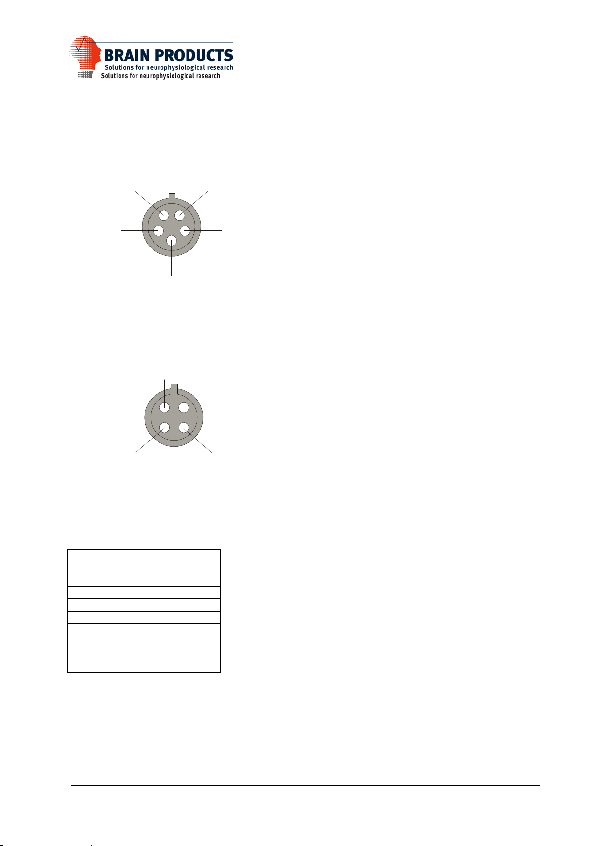
GND
+ Sig
+ 5V-5V
-Sig
Guard
+ Sig -Sig
AUX Connector (front view)
BIP Connector (Front view)
Pin
Input
2
bit 0 (LSbit)
(parallel to BNC connector in software)
3
bit 1
4
bit 2
5
bit 3
6
bit 4
7
bit 5
8
bit 6
9
bit 7
25
common ground
Appendix 3 Connector pinout
QuickAmp Manual
Digital input DB25 connector
15

DB37 pin number
First DB37
Channel number
Second DB37
Channel number
Third DB37
Channel number
Fourth DB37
Channel number
1 - - - -
20
1
33
65
97 2 2
34
66
98
21
3
35
67
99 3 4
36
68
100
22
5
37
69
101 4 6
38
70
102
23
7
39
71
103 5 8
40
72
104
24
9
41
73
105 6 10
42
74
106
25
11
43
75
107 7 12
44
76
108
26
13
45
77
109 8 14
46
78
110
27
15
47
79
111 9 16
48
80
112
28
17
49
81
113
10
18
50
82
114
29
19
51
83
115
11
20
52
84
116
30
21
53
85
117
12
22
54
86
118
31
23
55
87
119
13
24
56
88
120
32
25
57
89
121
14
26
58
90
122
33
27
59
91
123
15
28
60
92
124
34
29
61
93
125
16
30
62
94
126
35
31
63
95
127
17
32
64
96
128
36
Subject Ground
Subject Ground
Subject Ground
Subject Ground
18 - - - -
37 - - - -
19 - - - -
QuickAmp Manual
Headcap connector
This table describes the relation between signal channel numbers and headcap connector pin numbers.
Connector
Connector
Connector
Connector
16
 Loading...