


www.brainproducts.com
LiveAmp
Operating Instructions
Product revision 0-

LiveAmp | Operating Instructions
Product revision 04
Copy right
Any trademarks mentioned in this document are the protected property of their rightful owners.
The reproduction, distribution and utilization of this document as well as the communication of its contents to
others without express authorization is prohibited. Offenders will be held liable for the payment of damages. All
rights reserved in the event of the grant of a patent, utility model or design. Subject to change without notice.
For the latest version of this document, please visit www.brainproducts.com or contact your local distributor.
Published by Brain Products GmbH
Zeppelinstrasse 7
82205 Gilching
Germany
Published on* February 28, 2019 Document version 011
*Valid until publication of a new version of this document.
© 2019 Brain Products GmbH
Phone: +49 (0) 8105 733 84 - 0
Fax: +49 (0) 8105 733 84 - 505
Web: www.brainproducts.com

Contents
About the document....................................................................................................... 5
About the product .......................................................................................................... 8
Safety information ....................................................................................................... 12
1 Scope of delivery............................................................................................... 16
1.1 LiveAmp System...................................................................................... 16
1.2 Optional accessories for LiveAmp ............................................................ 17
3
2 Overview of the product .................................................................................... 21
2.1 LiveAmp at a glance ................................................................................ 21
2.2 Identifying your LiveAmp .........................................................................22
2.3 About the license dongle......................................................................... 23
3 Before you begin ............................................................................................... 24
3.1 Check the scope of delivery ..................................................................... 24
3.2 Installing the software and drivers........................................................... 24
3.3 Insert the memory card............................................................................ 25
3.4 Charge the battery of LiveAmp ................................................................. 26
3.5 Prepare the recording environment.......................................................... 27
4 LiveAmp Basics ................................................................................................. 28
4.1 Switch on/off LiveAmp ............................................................................ 28
4.2 Use a power bank ................................................................................... 29
4.3 Understanding the accelerometer............................................................ 29
5 Using LiveAmp 8, 16 and 32 .............................................................................. 30
5.1 Connect LiveAmp 8, 16 or 32 with Recorder ............................................. 30
5.2 Use the internal wireless adapter ............................................................ 31
5.3 Identify your LiveAmp 8, 16 or 32 ............................................................ 31
5.4 Connect/disconnect an electrode cap...................................................... 33
6Using LiveAmp 64............................................................................................. 34
6.1 LiveAmp 64............................................................................................. 34
6.2 Assemble the LiveAmp 64 ....................................................................... 34
6.3 Connect LiveAmp 64 with Recorder .......................................................... 36
6.4 Identify your LiveAmp 64 ......................................................................... 37
6.5 Connect/disconnect the actiCAP ............................................................. 38

7 Connect Trigger sources and Sensor and trigger extension................................ 40
7.1 Connect trigger sources........................................................................... 40
7.2 Use the Sensor and trigger extension Box (8 bit) ...................................... 42
7.3 Combine Sensor and trigger extension with a LiveAmp trigger .................. 44
7.4 Forward trigger signals ............................................................................ 45
7.5 Set the SyncOut ...................................................................................... 47
7.6 Connect sensors ..................................................................................... 47
8 Recording procedures ....................................................................................... 50
8.1 Record to the computer ........................................................................... 50
8.2 Record to LiveAmp .................................................................................. 51
8.3 Record to the computer and LiveAmp....................................................... 51
8.4 Record to LiveAmp as holter .................................................................... 52
9 Accessing your data .......................................................................................... 53
9.1 Eject the memory card ............................................................................. 53
9.2 Convert the data ..................................................................................... 55
9.3 Back-up the data of the memory card ...................................................... 56
9.4 Format the memory card.......................................................................... 58
4
10 After using LiveAmp .......................................................................................... 60
10.1 Clean LiveAmp and the accessories ......................................................... 60
10.2 Clean the electrode cap........................................................................... 60
10.3 Charge the battery of LiveAmp ................................................................. 61
10.4 Charge the power bank ........................................................................... 61
11 Maintenance, disposal and updates .................................................................. 62
11.1 Maintenance information ........................................................................ 62
11.2 Disposal information............................................................................... 62
11.3 Update the firmware of LiveAmp.............................................................. 63
12 Troubleshooting................................................................................................ 64
12.1 Knowing the status of LiveAmp................................................................ 64
12.2 Troubleshooting charts Issues with LiveAmp............................................ 65
12.3 Issues with LiveAmp 64........................................................................... 66
12.4 Battery / Charging issues ........................................................................ 66
12.5 Lost samples .......................................................................................... 68
12.6 Issues related to the physiological signals............................................... 68
12.7 Analyzer problems .................................................................................. 70
12.8 Sensor and trigger extension issues ........................................................ 70
12.9 Frequently asked questions..................................................................... 70
Appendix A Technical data ........................................................................................ 73

About the document 5
About the document
This document describes how to use LiveAmp and how it is integrated into a measurement setup.
This document forms an integral part of the product. It must be precisely adhered to in order to ensure that the product is used as intended and operated correctly to guarantee the concomitant safety of test subjects, users and third parties. Keep this document in a safe place and make sure that
it is always available to the users.
No part of this document may be reproduced or distributed in any form without the express written
permission of Brain Products. The operator may print this document to make it available for the users of the product.
Make sure that you have the most recent version of this document for your product or product revision. You can find the most recent version on our website: http://www.brainproducts.com
.
Target group of this document
This document is intended for users in the psychological and neurophysiological research area as
well as physicians and medical experts with experience in performing physiological data acquisition. Staff must also know how to work safely and reliably with the permitted amplifier and the associated recording software.
Structure of this document
This document is divided into the following chapters:
Chapter 1: Scope of delivery.
Chapter 2: Overview of the product, licenses required, accessories and their main features.
Chapter 3: Preparing the product for use.
Chapter 5: Setting up and using LiveAmp 8, 16 and 32.
Chapter 6: Setting up and using the LiveAmp 64.
Chapter 7: How to connect trigger sources and the Sensor and trigger extension.
Chapter 8: How to record your data.
Chapter 9: How to access your data.
Chapter 10: Cleaning and further activities after using the product.

About the document 6
!
NEW
Chapter 11: Maintenance information.
Chapter 12: Troubleshooting and frequently asked questions.
Appendix A: Technical data.
Conventions in this document
Typographical conventions
Bold indicates items on the user interface (menus, buttons, switches, connectors,
options) and is used for emphases in the text
Italic indicates titles of dialog boxes/tabs, file locations and is used to indicate
product names
Underscore
Monospaced indicates text or characters to be entered at the keyboard
indicates cross-references and web addresses
Symbols
Caution: This symbol indicates that incorrect use of the product(s) may result in a per-
sonal injury to the test subject, the user and/or a third-party. Failure to observe the
information in this document constitutes incorrect use.
Notice: This symbol indicates that the incorrect use of the product(s) may bring about
a risk of damage to property. Failure to observe the information in this document constitutes incorrect use.
Note or Tip: This symbol draws your attention to important information relating to the
current topic and to recommendations on how to use the product(s).
Cross-reference: This symbol indicates a reference to a related chapter, section or
document.
New: This symbol indicates changes or new content at this point.

About the document 7
Revision history
Page Status Change
9 modified IEC/EN safety standard updated.
55 modified Procedure updated as File Converter now offers the option to convert multiple files.
75 modified Impedance measurement range updated.
Reporting errors and support
We would ask you to report without delay any error you find in this document, any fault on the products or any malfunction that you observe when using this product. To do so, please contact your local dealer, who will also assist you in general questions about the product.
z

About the product 8
About the product
LiveAmp is an ultra-lightweight, wearable amplifier that is available in three different models.
- LiveAmp 8 can record a total of 8 channels, unipolar and/or bipolar.
- LiveAmp 16 can record a total of 16 unipolar channels with a maximum of 8 bipolar channels.
- LiveAmp 32 can record either 32 unipolar channels or 24 unipolar and 8 bipolar channels.
As it is wireless and allows you to store the data internally (exchangeable memory card), there are
no mobility limitations. LiveAmp is easy and intuitive to use and extremely compact. Its technical
specifications leave nothing to be desired and translate into outstanding signal quality. LiveAmp
can be combined with all available Brain Products electrode types, passive/active or dry.
Bipolar recording is only possible with passive electrodes.
Product identification
Product designation LiveAmp wireless amplifier
Article number LiveAmp 32 channel: BP-200-3000
LiveAmp 16 channel: BP-200-3010
LiveAmp 8 channel: BP-200-3020
Manufacturer Brain Products GmbH
Zeppelinstrasse 7
82205 Gilching
Germany
Tel: +49 (0) 8105 733 84 - 0
Fax: +49 (0) 8105 733 84 - 505
Web: http://www.brainproducts.com
Email: techsup@brainproducts.com
Warranty http://www.brainproducts.com/contact.php

Combinations with other products
NEW
LiveAmp is permitted to be combined with the following products:
Product Manufacturer
BrainVision Recorder (as of version 1.21) Brain Products GmbH
BrainVision LiveAmp File Converter Brain Products GmbH
EEG caps and electrodes Brain Products GmbH
Easy Cap GmbH
32 GB micro memory card, class 10
Transcend
®
About the product 9
Powerbank with >= 10,000 mAh
Should conform to all national safety and product standards or directives in the country of
use. The selected powerbank should be tested
(signal noise, operating time, etc.) before first
use
BNC push button Brain Products GmbH
Computer The computer connected to the amplifier
should at a minimum fulfill the IEC/EN 62368-1
or IEC/EN 60950-1 safety standard.
Beside this general statement about permitted product combinations the user must check, whether
all stipulations of each product (e.g. regarding its MR compatibility) are fulfilled for the specific combination and purpose of application (i.e. intended use and correct use). Please observe the operating instructions of the respective products.

Markings on the products
The following markings are displayed on the product label:
Brain Products GmbH confirms the compatibility of this product according to the
DIRECTIVE 2014/53/EU (RED) OF THE EUROPEAN PARLIAMENT AND OF THE COUNCIL
of 16 April 2014 on the harmonisation of the laws of the Member States relating to
the making available on the market of radio equipment.
This symbol confirms compliance with the environmental requirements for electronic products (only applies to China).
This symbol indicates that defective products must not be disposed of with the
household waste. Dispose of them in accordance with national regulations or return
the product and its accessories to the manufacturer.
MR Unsafe: Products with this symbol must not be used in an MR environment.
About the product 10
Observe the operating instructions.
Next to this symbol, the name and address of the product manufacturer is specified.
No contact with liquids: Make sure that liquids do not enter the enclosure.
Japan
MIC ID: R 204-210003
Japan Radio Equipment Compliance: Japanese Technical Regulation Conformity Certification of Specified Radio Equipment, Article 2, Paragraph 1, Item 19, ‘2.4 GHz
band wide band low power data communication system’.
Canada
Contains transmitter module IC: 5325A-0946
This device complies with Industry Canada license-exempt RSS standard(s). Operation is subject to the following two conditions: (1) this device may not cause interference, and (2) this device must accept any interference, including interference
that may cause undesired operation of the device.
Le présent appareil est conforme aux CNR d'Industrie Canada applicables aux appareils radio exempts de licence. L'exploitation est autorisée aux deux conditions
suivantes: (1) l'appareil ne doit pas produire de brouillage, et (2) l'utilisateur de
l'appareil doit accepter tout brouillage radioélectrique subi, même si le brouillage
est susceptible d'en compromettre le fonctionnement

About the product 11
USA
Contains FCC ID: PVH0946
This device complies with Part 15 of the FCC Rules. Operation is subject to the following two conditions:
(1) this device may not cause harmful interference,
and
(2) this device must accept any interference received, including interference that
may cause undesired operation.
This equipment has been tested and found to comply with the limits for a Class B
digital device, pursuant to part 15 of the FCC Rules. These limits are designed to
provide reasonable protection against harmful interference in a residential installation. This equipment generates, uses and can radiate radio frequency energy, and if
not installed and used in accordance with the instructions, may cause harmful interference to radio communications. However, there is no guarantee that interference
will not occur in a particular installation. If this equipment does cause harmful interference to radio or television reception, which can be determined by turning the
equipment off and on, the user is encouraged to try to correct the interference by
one or more of the following measures:
• Reorient or relocate the receiving antenna
• Increase the separation between the equipment and receiver
• Consult your Brain Products dealer for help.
z

Safety information 12
Safety information
Please read the following safety information carefully since it helps to prevent personal injury and
damage to property. It is assumed that you have the required specialist knowledge in handling the
product and accessories.
Brain Products will not accept any liability for loss or damage resulting from a failure to follow these
operating instructions and, in particular, the safety instructions.
Intended use
LiveAmp is intended to be used for amplifying and digitizing electrophysiological signals (for example EEG, EMG, ECG, EOG).
LiveAmp is not a medical device. It may be used in the context of non-medical applications in order
to carry out fundamental or applied research on the basis of neurophysiological methodology and
data. Use of LiveAmp for diagnosis, therapy, monitoring of vital physiological processes (such as
cardiovascular functions etc.) or other medical purposes is expressly forbidden.
Correct use
LiveAmp is permitted to be used:
by personnel in the psychological and neurophysiological research area as well as physicians
and medical experts.
in research institutes and other non-medical environments (e.g. at home), hospitals, clinics and
other medical environments, provided that all other stipulations regarding the correct use are
met and that the products are used in accordance with its intended use.
LiveAmp must not be used:
by unqualified persons (e.g. laymen) and persons who cannot read (e.g. due to visual impair-
ment) or understand (e.g. due to a lack of language skills) this document.
in MR scanner environment.
in vicinity of explosive gases, for example in operating theaters.
in oxygen enriched atmospheres.
under water (e.g. sea, swimming pool, bath tub) or in environments in which significant amounts
of water could enter the products (e.g. under shower, in the rain).
The user is solely liable for any risks to test subjects associated with the investigation if the product
is not used in accordance with the correct use.
Safety information 13
!
CAUTION
Risk of burns by damaged battery
If water enters LiveAmp or if LiveAmp is completely submerged in water, or is otherwise damaged, swollen, cracked, or opened, the battery might be rendered defective.
A defective battery can catch fire and cause burns.
In order to protect the battery:
- do not drop LiveAmp.
- avoid impacts on the housing.
- do not open and do not modify LiveAmp.
- do not submerge in water or let water enter LiveAmp.
If you notice leakages or a swollen housing, immediately switch off LiveAmp and stop
using it. Contact your local distributor. Do not ship damaged or potentially defective
LiveAmps to your local distributor or Brain Products GmbH unless instructed otherwise.
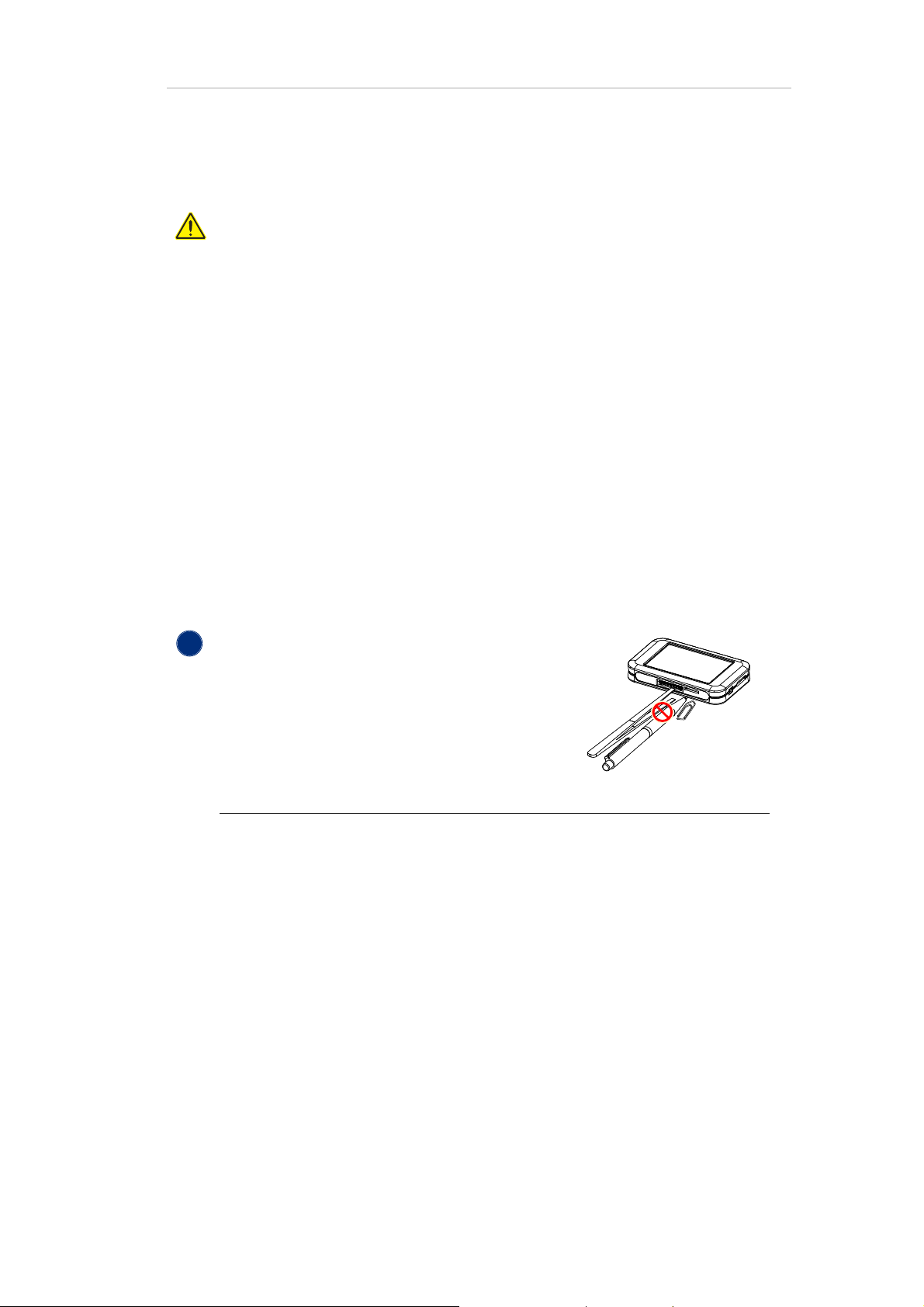
NOTICE
Damage to connectors when using tools
If you use tools, for example to remove the memory
card, you can accidentally touch the pins of the connectors. This can cause damage to LiveAmp.
Don’t use tools when removing or inserting the memory
card.
Damage by water
LiveAmp is not splash-water protected. Water or liquids, even small amounts, can
damage LiveAmp. This includes internal components, like the battery. Conditions in
which liquids could enter LiveAmp are, for example:
-rain
- close to or in water
-sweat
-bathroom
This list is not exhaustive. Please contact your distributor for consultation.
Don’t use in conditions where liquids could enter LiveAmp.

Safety information 14
!
NOTICE
Damage by mechanical force
A force applied to the housing of LiveAmp, for example strong impact, twisting, shakin g, can result in dama ge to Li veAmp. Th is includes internal components, like the battery. A damaged battery can cause fire.
Don’t use in conditions where a force could be applied to LiveAmp.
General precautions
Do not open the LiveAmp and its accessories.
Heat, direct sunlight (UV radiation), moisture, dust, liquids, conductive foreign
matter and excessive radiation shorten the lifespan of the product.
Use the supplied cables. Brain Products is not liable for damage caused by cables
that are not supplied by Brain Products.
Do not unplug connectors by pulling on their cable. Instead unplug a connector by
releasing the locks (if applicable) and by pulling on the connector itself.
Do not crush or kink the cables.
Notes on the data quality
Only use the supplied memory card or a memory card that matches the specifica-
tions to avoid data loss.
The user is responsible for the appropriate measurement setup and the quality of
the recorded data.
During operation, keep a minimum distance of three meters to cell phones or sim-
ilar transmission equipment. Otherwise, signals may be distorted or contain artifacts.
Do not attach the products to metallic surfaces. This will impair the wireless con-
nection.

Safety information 15
Storing and transporting LiveAmp
Always store LiveAmp in the supplied case on a dark, dry place. Avoid direct sunlight (UV radia-
tion), moisture and dust.
Use the supplied case, when you transport LiveAmp.
The temperature must be within 0 °C (32 °F) to 40 °C (104 °F).
Note
To prevent mechanical damage during transport, please pack the product in such a
way, that it is not subject to vibration.
Note on the Lithium-Ion battery
Location of the battery General data of the battery
- Type: Lithium-Ion battery in shrink sleeve
- 1 cell with approx. 18 g
- Rated capacity: 1,000 mAh
- Watt-Hour rating: 3.7 Wh
z
1 Scope of delivery
1.1 LiveAmp System
The LiveAmp System is available in three versions:
- LiveAmp 32 channel: BP-100-3000
- LiveAmp 16 channel: BP-100-3010
- LiveAmp 8 channel: BP-100-3020
16
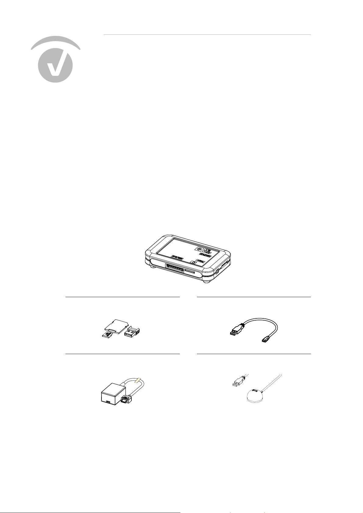
LiveAmp wireless amplifier
LiveAmp 32 channel: BP-200-3000
LiveAmp 16 channel: BP-200-3010
LiveAmp 8 channel: BP-200-3020
32 GB micro memory card & USB card reader
BP-350-6000 & BP-350-6010
LiveAmp USB adapter
BP-245-5020
USB cable (15 cm / 6 in.)
BP-345-1045
USB extension cable (150 cm / 59 in.)
BP-350-9010

1 Scope of delivery 17
Wireless adapter (UBT21)
BP-310-6000
USB charger with adapter
BP-315-1010
Application Suite USB (not illustrated)
BP-270-6010
Trigger cable (80 cm / 31 in.)
BP-245-1200
License dongle (black)
BP-00060-UR
LiveAmp Case (not illustrated)
BP-390-1040
1.2 Optional accessories for LiveAmp
The following are additional items that can be purchased for use with your LiveAmp.
1 Scope of delivery 18
Adapters for electrode cap systems
The following electrode cafp systems are available for LiveAmp. The illustrations show the various
connectors for the cap systems:
actiCap slim 64-channel active electrode system for LiveAmp 64
BP-130-1107
LiveCap 32-channels with multitrodes
BP-330-1300
LiveCap 64
BP-330-1310
actiCAP snap 32-channel active electrode
system
BP-130-1105
actiCAP Xpress Twist for LiveAmp
BP-130-1200

Special Adapter
LiveAmp to standard actiCAP electrode set
incl. Ref and GND
BP-110-2100
1 Scope of delivery 19
Sensor and trigger extension kit for LiveAmp
The following articles are part of the Sensor and trigger extension kit:
Sensor and trigger extension for LiveAmp
BP-210-2000
USB-Power extender (similar to illustration)
BP-315-6000
Sensor and trigger cable (80 cm / 31 in.)
BP-245-1220

Trigger switches (optional)
1 Scope of delivery 20
Trigger push button
BP-245-5040
BNC push button, 1.9 m (75 in.)
BP-345-9000
z

2 Overview of the product
2.1 LiveAmp at a glance
21
1 I/O button (on/off)
2 Wireless LED, Battery/recording LED
3 AUX/PWR input
4 Trigger input
5 Memory card slot
6 Electrode connector
7 Connector rails

2.2 Identifying your LiveAmp
Serial number:
You can identify your LiveAmp by the serial
number. It is located on the type plate at the
bottom of your LiveAmp.
Reference number:
You can identify your version of LiveAmp by
the reference number.
BP-200-3000 - LiveAmp 32 Channel
BP-200-3010 - LiveAmp 16 Channel
BP-200-3020 - LiveAmp 8 Channel
2 Overview of the product 22
Understanding the LEDs
1 Battery/recording LED
Different colors indicate the battery state from green (= full) to red (= empty).
OFF LiveAmp is OFF.
ON LiveAmp is ON (any color),
Charging completed (green) when connected to a power source
blinking slow, green LiveAmp is charging.
blinking fast, any color Recording to memory card
2 Wireless LED
This LED is blue.
OFF Wireless module is OFF.
ON Wireless module is ON, but LiveAmp is not connected with Recorder.
blinking LiveAmp is connected with Recorder.

Sensor and trigger extension at a glance
1 Connector for power supply
2 Auxiliary inputs for sensors
2 Overview of the product 23
3 Signal output to LiveAmp
4 Trigger input
5 DC out (currently not used)
6 Power LED (lights up, when power source is connected)
7 Trigger output
2.3 About the license dongle
The labeling of the license dongle consists of the license type and 5-digit serial number. License
types are:
- Unnnnn: Analyzer local license
- Nnnnnn: Analyzer network license
- Rnnnnn or URnnnnn: Recorder professional license
- URnnnnn: Recorder license for LiveAmp
- URnnnnn: Recorder license for actiCHamp
- URnnnnn: Recorder license for BrainAmp
- VURnnnnn: Recorder license for V-Amp
- URAnnn: Analyzer/Recorder license
- VURAnnnnn: combined Analyzer/Recorder license for V-Amp
- UCnnnnn: CapTrak license
For further information please visit: http://www.brainproducts.com/productreg.php

3 Before you begin
3.1 Check the scope of delivery
LiveAmp wireless amplifier (32, 16 or 8 channel version)
LiveAmp USB adapter
32 GB micro memory card & USB card adapter
USB cable
Wireless adapter (transparent)
USB extension cable
USB charger with adapter
Trigger cable
Application Suite USB
License dongle (black)
Electrode cap (optional)
Trigger push button (optional)
Sensor and trigger extension (optional)
24
3.2 Installing the software and drivers
Before the first use, install BrainVision Recorder and BrainVision LiveAmp File Converter. The installation of Recorder includes the recording software and all relevant drivers.
The latest version of Recorder is on the Application Suite USB and also available on our website:
http://www.brainproducts.com/downloads.php
Quick installation procedure:
1 Insert the Application Suite USB stick into your computer.
The Welcome screen opens.
2 Install the BrainVision Recorder.
.

3 Install the BrainVision LiveAmp File Converter.
For details on installing Recorder, please refer to the Recorder user manual.
3.3 Insert the memory card
The memory card allows you to record data to LiveAmp.
Prepare:
- Micro memory card
- LiveAmp amplifier (it is switched off)
3 Before you begin 25
1 If applicable, switch off LiveAmp (all LEDs are OFF).
2 Insert the memory card into the card slot of the amplifier
until you hear a click.
Î You can now record data to the memory card in LiveAmp.

3.4 Charge the battery of LiveAmp
Before the first use and after each use, fully charge the battery of LiveAmp.
Prepare:
- LiveAmp amplifier
- USB cable (15 cm)
- USB adapter
- USB charger or computer with USB port
1 Connect the USB adapter to LiveAmp.
3 Before you begin 26
2 Connect the USB cable to the USB adapter.
3 Connect the USB cable to the USB charger,
and plug the charger into the power socket.
Alternatively, connect the USB cable to an
USB port of your computer.
Î The battery LED blinks green, when LiveAmp is
charging.
When LiveAmp is connected with Recorder,
the battery icon in the status bar blinks.
Fully charged
When the battery is fully charged, the battery LED is on continuously. It takes approximately four
hours to charge a completely empty battery.
After charging:
Disconnect LiveAmp from the power source.
Do not leave connected to the charger, if LiveAmp is not in use.

3 Before you begin 27
Disconnect the USB adapter
1 Push and hold the release button on the con-
nector.
2 Pull the connector from LiveAmp.
Charge the power bank
Before the first use and after each use, fully charge the power bank.
To charge the power bank follow the operating instructions of the manufacturer of the power bank.
3.5 Prepare the recording environment
Prepare the recording environment, to avoid interferences with other radio devices and to improve
the operating range of LiveAmp.
1 Remove obstacles in the signal path.
For example, if there is a door between the recording computer and LiveAmp, then leave the door
open. The same applies for movable walls, hatstands, etc.
2 Switch off devices that could cause interferences.
LiveAmp uses the ISM band (2.4 GHz). Interference can be caused by equipment in the same
band, for example:
Bluetooth
Wi-Fi
mobile phones
microwave oven
®
(for example, keyboard, mouse, and mobile phones)
®
z

4 LiveAmp Basics
V
V
4.1 Switch on/off LiveAmp
Switch on
28
1 Press and hold the I/O button for five seconds.
The battery LED flashes.
2 When the battery LED lights continuously, release
the I/O button.
Switch off
Î The wireless LED automatically comes on when Live-
Amp is running.
1 Press and hold the I/O button for three seconds.
2 When the battery LED flashes and the wireless LED
goes off, release the I/O button.
Î LiveAmp turns off after another three seconds.
Î While charging, LiveAmp does not turn off complete-
ly.

4 LiveAmp Basics 29
nj
LJ
dž
4.2 Use a power bank
You can use a power bank during recording to charge the LiveAmp battery. This will extend the recording period.
Don’t connect the power bank if you use actiCAP Xpress Twist.
4.3 Understanding the accelerometer
LiveAmp has an integrated accelerometer. It shows the acceleration in the x, y, and z direction. The
directions are as follows:
Figure 4-1. x, y, and z axes of the accelerometer
z

5 Using LiveAmp 8, 16 and 32
5.1 Connect LiveAmp 8, 16 or 32 with Recorder
To start data recording, LiveAmp must be connected wirelessly with Recorder. Use the supplied
wireless adapter to make the connection.
For optimal performance your LiveAmp should be running the latest firmware version.
Refer to the Recorder User Manual section Show connected amplifier to check the current firmware version. Refer to Update the firmware of LiveAmp
update the firmware.
for details on how to
30
Prepare
- USB extension cable
- Wireless adapter
- LiveAmp amplifier (with memory card)
- Computer with Recorder 1.21.0201 or higher
1 Connect the wireless adapter with the USB ex-
tension cable to your computer.
To use another wireless adapter see Use the in-
ternal wireless adapter.
2 Position the wireless adapter within line-of-sight
of LiveAmp.
3 Start Recorder (in administrator mode) and
choose LiveAmp from the menu Configuration >
Select amplifier...
The LiveAmp Console opens.
4 Switch on LiveAmp.

5 In the LiveAmp Console click on Search for Live-
!
Amp...
6 Select the LiveAmp and click on Connect.
(See also Identify your LiveAmp 8, 16 or 32
Î The blue LED of the wireless adapter is ON and
the wireless LED of LiveAmp is blinking. LiveAmp
is now connected with Recorder.
5.2 Use the internal wireless adapter
5 Using LiveAmp 8, 16 and 32 31
.)
By default, Recorder uses the wireless adapter UBT21. To use the internal adapter of your computer
instead, do the following:
1 Start Recorder (no amplifier connected).
2 Click on Amplifier > Wireless Settings...
3 The Wireless Settings window opens.
4 Select the check box and click OK.
Î You can now use the internal wireless adapter of your
computer.
5.3 Identify your LiveAmp 8, 16 or 32
You identify the LiveAmps by their serial numbers. The serial number starts with ‘LA-’.
The LiveAmps within Range window lists all
LiveAmp amplifiers with their serial numbers
that were detected during the scan.

5 Using LiveAmp 8, 16 and 32 32
You can find the serial number on the type
plate at the bottom of your LiveAmp.
To read the serial number, you can disconnect
the electrode connector without turning off
LiveAmp.

5 Using LiveAmp 8, 16 and 32 33
5.4 Connect/disconnect an electrode cap
You can connect electrode caps with passive, active or dry electrodes to LiveAmp. Only use the dedicated electrode caps for LiveAmp.
Prepare
- LiveAmp amplifier
- Electrode cap for LiveAmp
Connect
Disconnect
1 Switch off LiveAmp.
2 Slide the connector on the LiveAmp.
3 Push the connector as far as it will go.
4 Turn on LiveAmp.
1 Switch off LiveAmp.
2 Slide the connector from LiveAmp.
z

6 Using LiveAmp 64
6.1 LiveAmp 64
LiveAmp 64 allows you to connect two LiveAmp 32 channel units giving you either 64 unipolar channels or 56 unipolar and 8 bipolar channels. Currently we offer two LiveAmp 64 options:
actiCap slim 64-channel active electrode system for LiveAmp 64: BP-130-1107.
LiveCap 64: BP-330-1310
Illustrated in this section is the actiCap slim 64-channel active electrode system for LiveAmp 64
(LiveAmp 64).
34
To use LiveAmp 64 both of your LiveAmps must be running firmware version 4.60 or
later. Refer to the Recorder User Manual section Show connected amplifier to check
the current firmware version. Refer to Update the firmware of LiveAmp
how to update the firmware.
for details on
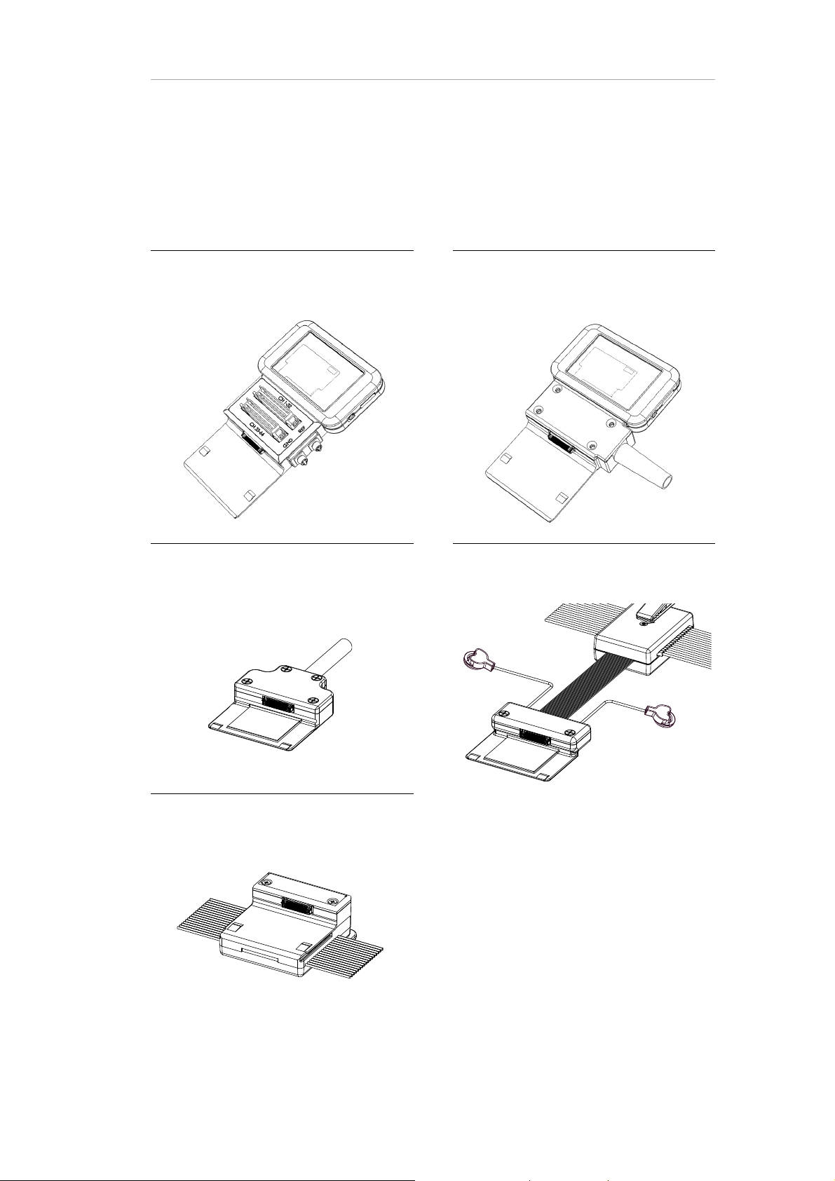
6.2 Assemble the LiveAmp 64
The LiveAmp 64 has to be assembled before use.
Prepare
- actiCap slim 64-channel active electrode system for LiveAmp 64 or LiveCap 64
- 2 x LiveAmp 32 amplifiers (with memory cards if required)

6 Using LiveAmp 64 35
1 Identify master and slave LiveAmps:
CH 1-32, this LiveAmp will serve as the master
LiveAmp.
CH 33-64, this LiveAmp will serve as the slave
LiveAmp.
2 Ensure the LiveAmps are turned off.
3 Using the mount as a guide, slide the LiveAmp on
to the adapter and push to create a secure connection with the connector.
4 Repeat with the second LiveAmp on the other
connector.
Î The LiveAmp 64 is now assembled and ready for
use.

6 Using LiveAmp 64 36
6.3 Connect LiveAmp 64 with Recorder
To record data, LiveAmp 64 must be connected wirelessly with Recorder. Use the supplied wireless
adapters to make the connection.
Prepare
- 2 x USB extension cable
- 2 x Wireless adapter
- LiveAmp 64 (with memory cards if required)
- Computer with Recorder 1.21.0303 or higher
1 Connect the wireless adapters with the USB ex-
tension cable to your computer.
To ensure reliable data transmission keep the
wireless adapters at least 50cm apart.
2 Position the wireless adapters within line-of-
sight of LiveAmp.
3 Start Recorder (in administrator mode) and
choose LiveAmp 64 from the menu Configura-
tion > Select amplifier...
The LiveAmp Console opens.
4 Switch on each LiveAmp by pressing and holding
the power button for five seconds.
5 In the LiveAmp Console click on Search for Live-
Amp...
6 Select the LiveAmp 64 and click on Connect.
(See also Identify your LiveAmp 64
.)

6 Using LiveAmp 64 37
!
Î The blue LED of the wireless adapter is ON and
the wireless LED on both LiveAmps are blinking.
LiveAmp is now connected with Recorder.
6.4 Identify your LiveAmp 64
You identify the LiveAmp 64 using the last four digits of master LiveAmp amplifier’s serial number.
The LiveAmps within Range window lists any
LiveAmp 64 amplifiers that were detected
during the scan.
The LiveAmp 64 is listed with the last four digits of the master LiveAmp amplifier’s serial
number.
You can find the serial number on the type plate
at the bottom of your master LiveAmp.
CH 1 - 32 = master LiveAmp
CH 33 - 64 = slave LiveAmp
To read the serial number turn off the LiveAmp
amplifier and disconnect it from the adapter.

6.5 Connect/disconnect the actiCAP
Not applicable to LiveCap 64.
Prepare
- LiveAmp 64
-actiCAP
Connect
6 Using LiveAmp 64 38
1 Switch off the LiveAmps.
2 Connect the electrode cap.
3 Connect the GND and REF cable.
4 Turn on the LiveAmps.

Disconnect
6 Using LiveAmp 64 39
1 Switch off the LiveAmps.
2 Remove the electrode cap from the corresponding
connector.
z

40
7 Connect Trigger sources and Sensor and trigger
extension
7.1 Connect trigger sources
LiveAmp 8, 16 and 32 has an input for one trigger bit. When using LiveAmp 64 it is possible to connect two trigger bits, one to each LiveAmp amplifier. To connect more trigger bits, use the Sensor
and trigger extension for LiveAmp.
Always disconnect LiveAmp from Recorder before connecting or disconnecting the
sensor and trigger extension.
Use a trigger with LiveAmp 8, 16, 32 channel (1 bit)
Prepare
- LiveAmp 8, 16, 32
- trigger cable (with stereo and BNC connector) or the trigger push button
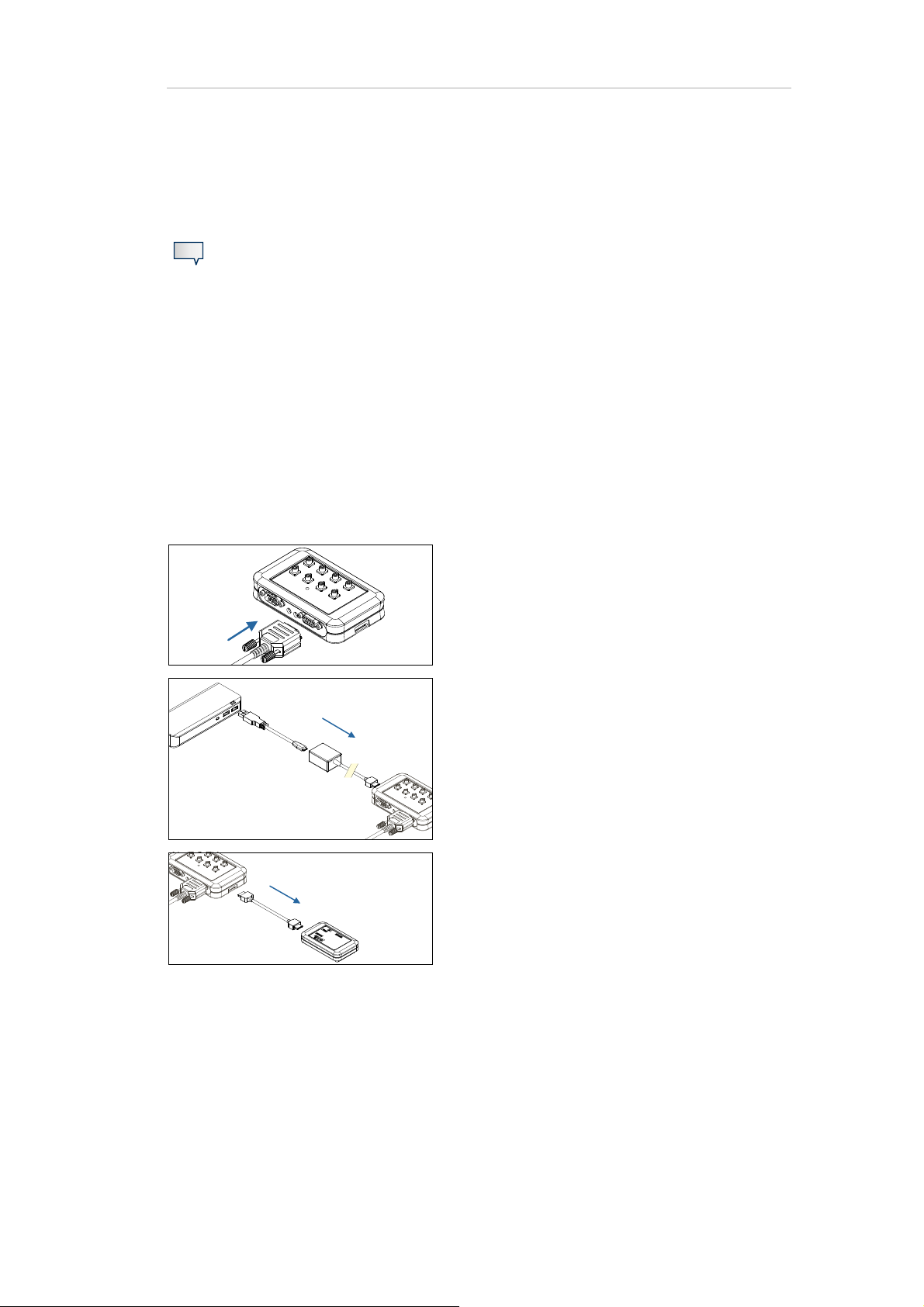
1 Connect the trigger cable or trigger push button
to the trigger input of the LiveAmp.
2 Power on the LiveAmp and connect with Record-
er.
3 In Recorder, open the Digital Port Settings (Am-
plifier > Digital Port Settings...) and adjust the
settings.

7 Connect Trigger sources and Sensor and trigger extension 41
4 Select the Bit 0 check-box to enable the trigger.
Î Check your setup by using the Current State as a
guide. The black and red bullets indicate the
state of your trigger sources. Activate a trigger to
check if the state of the bullet changes and that
a marker will be set. If the bullet does not
change, then adapt the Low Active and High Active settings.
Use a LiveAmp trigger with LiveAmp 64 channel (2 bit)
Prepare
-LiveAmp 64
- Trigger cable (with stereo and BNC connector) or the trigger push button
1 Connect the trigger cable or trigger push button
to the trigger input of the required LiveAmp. The
trigger can be connected to either the slave or
master LiveAmp, by using both you can have a 2
bit trigger.
CH 1 - 32 = Master LiveAmp
CH 33-64 = Slave LiveAmp
2 Power on the LiveAmps and connect with Record-
er.
3 In Recorder, open the Digital Port Settings (Am-
plifier > Digital Port Settings...) and adjust the
settings.
4 Select the Bit 0 and/or the Bit 1 check-box to en-
able/disable the trigger/s.
- Bit 0 is the trigger input from the master LiveAmp
- Bit 1 is the trigger input from the slave LiveAmp

7 Connect Trigger sources and Sensor and trigger extension 42
Î Check your setup by using the Current State as a
guide. The black and red bullets indicate the
state of your trigger sources. Activate a trigger to
check if the state of the bullet changes and that
a marker will be set. If the bullet does not
change, then adapt the Low Active and High Active settings.
7.2 Use the Sensor and trigger extension Box (8 bit)
Prepare
- LiveAmp 8, 16, 32 or LiveAmp 64
- Sensor and trigger extension for LiveAmp
- Trigger cable (D-Sub)
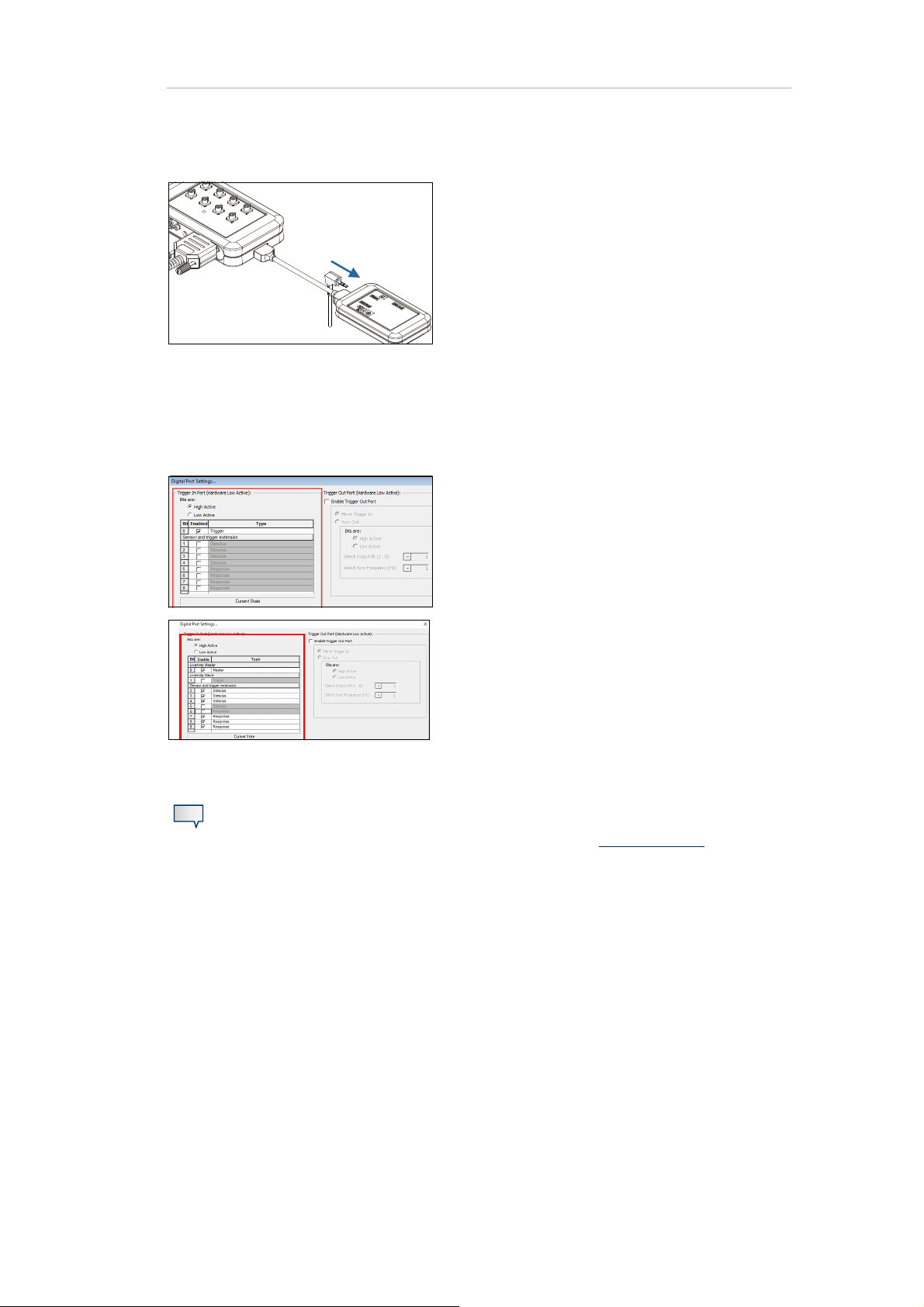
1 Connect the trigger cable to Trigger In of the Sen-
sor and trigger extension.
2 Connect the power bank to the Sensor and trig-
ger extension by using the USB adapter.
3 Connect the Sensor and trigger extension to the
AUX/PWR input of LiveAmp.
When using LiveAmp 64 the Sensor and trigger
extension can be connected to either the slave or
master LiveAmp.
CH 1 - 32 = Master LiveAmp
CH 33-64 = Slave LiveAmp
4 Power on the LiveAmp/s and connect with Re-
corder.

7 Connect Trigger sources and Sensor and trigger extension 43
5 In Recorder, open the Digital Port Settings (Am-
plifier > Digital Port Settings...) and adjust the
settings.
LiveAmp 8, 16, 32:
Select the corresponding Sensor and trigger extension check-box to enable or disable the trigger in bit.
LiveAmp 64
Select the corresponding Sensor and trigger extension check-box to enable or disable the trigger in bit.
Î Check your setup by using the Current State as a
guide. The black and red bullets indicate the
state of your trigger sources. Activate a trigger to
check if the state of the bullet changes and that
a marker will be set. If the bullet does not
change, then adapt the Low Active and High Active settings.
Note
Additionally, you can connect up to eight sensors to the auxiliary inputs. Refer to Con-
nect sensors.
7 Connect Trigger sources and Sensor and trigger extension 44
7.3 Combine Sensor and trigger extension with a LiveAmp trigger
Note
LiveAmp 8, 16 and 32 up to nine trigger bits can be used.
LiveAmp 64 up to ten trigger bits can be used.
Prepare
- LiveAmp 8, 16, 32 or LiveAmp 64
- Sensor and trigger extension for LiveAmp
- Trigger cable (BP-245-1200) or trigger push button (BP-245-5040)
- Trigger cable (9-pin D-Sub, male)
-USB power bank
- USB adapter
1 Connect the trigger cable to Trigger In of the Sen-
sor and trigger extension.
2 Connect the power bank to the Sensor and trig-
ger extension by using the USB adapter.
3 Connect the Sensor and trigger extension to the
AUX/PWR input of LiveAmp.
When using LiveAmp 64 the Sensor and trigger
extension can be connected to either the slave or
master LiveAmp.
CH 1 - 32 = Master LiveAmp
CH 33-64 = Slave LiveAmp
7 Connect Trigger sources and Sensor and trigger extension 45
4 Connect the trigger cable (for example BP-245-
1200) to the Trigger input of LiveAmp.
5 Power on the LiveAmp/s and connect with Re-
corder.
6 In Recorder, open the Digital Port Settings (Am-
plifier > Digital Port Settings...) and adjust the
settings.
LiveAmp 8, 16, 32:
Select the corresponding check-box to enable or
disable the trigger in bit.
LiveAmp 64
Select the corresponding check-box to enable or
disable the trigger in bit.
- Bit 0 is the trigger input from the master LiveAmp
- Bit 1 is the trigger input from the slave LiveAmp
- Bits 2 to 9 are from the sensor and trigger extension
Note
Additionally, you can connect up to eight sensors. Refer to Connect sensors
.
7.4 Forward trigger signals
The Sensor and trigger extension allows you to forward trigger signals to other devices.
Prepare
- Cable for the Trigger In port (9-pin male D-Sub)
- Cable for the Trigger Out port (9-pin female D-Sub)

7 Connect Trigger sources and Sensor and trigger extension 46
1 Connect the trigger source to Trigger In of the
Sensor and trigger extension.
2 Connect a suitable cable to the Trigger Out of the
Sensor and trigger extension.
3 In Recorder, open the Digital Port Settings (Am-
plifier > Digital Port Settings...) and adjust following settings:
Choose Enable Trigger Out Port.
Choose Mirror Trigger In.
Î For LiveAmp 8, 16 and 32 trigger bit 1 is output to
trigger bit 1 of trigger out port.
Î For LiveAmp 64 Trigger bit 2 is output to trigger
bit 1 of trigger out port.

7 Connect Trigger sources and Sensor and trigger extension 47
7.5 Set the SyncOut
The Trigger Out connector on the Sensor and trigger extension can be used to output a synchronization signal on one specific bit.
The synchronization signal can be used to offline re-synchronize two different types of data
streams.
Prepare
- Cable for the Trigger Out port (9-pin female D-Sub)
1 Connect a suitable cable to the Trigger Out of the
Sensor and trigger extension.
2 In Recorder, open the Digital Port Settings (Am-
plifier > Digital Port Settings...) and adjust following settings:
Choose Enable Trigger Out Port.
Choose Sync Out and change the settings.
Î The synchronization signal will now be output at
the selected bit with the selected frequency. In
the example, Bit 1 with 10 Hz.
At the same time a SyncOut marker is set in Re-
corder.
7.6 Connect sensors
You can connect up to eight sensors to LiveAmp by using the Sensor and trigger extension.
Prepare
- LiveAmp amplifier (electrode cap connected and prepared)

7 Connect Trigger sources and Sensor and trigger extension 48
- Sensor and trigger extension for LiveAmp
-USB power bank
- USB adapter
-USB cable
- Sensor and trigger cable
1 Prepare the test subject.
2 Connect the sensors to the Sensor and trigger ex-
tension.
3 Connect the power bank to the Sensor and trig-
ger extension by using the USB adapter.
4 Connect the Sensor and trigger extension to the
input AUX/PWR of LiveAmp by using the supplied
connecting cable.
When using LiveAmp 64 the Sensor and trigger
extension can be connected to either the slave or
master LiveAmp.
CH 1 - 32 = Master LiveAmp
CH 33-64 = Slave LiveAmp
5 Select the Sensor and trigger extension in the Re-
corder workspace.
Î When you specify the number of auxiliary chan-
nels, the channels will be added at the end of the
channel table.

Note
7 Connect Trigger sources and Sensor and trigger extension 49
Additionally, you can connect trigger sources. Refer to Connect trigger sources
.
z

8 Recording procedures
LiveAmp allows you to write data to different locations.
You can try out each recording procedure even without electrodes. To do so, open the LiveAmp workspace and select passive electrodes.
LiveAmp 8 channel and LiveAmp 16 channel require BrainVision Recorder version
1.21.0201 or later.
LiveAmp 64 requires BrainVision Recoder version 1.21.0303 or later.
50
General prerequisites:
- memory card inserted (if required)
- LiveAmp connected with Recorder
- workspace created
8.1 Record to the computer
EEG data is written to the recording computer only. During the recording LiveAmp must stay in the range of the wireless connection.
If you move LiveAmp out of the wireless range, samples will be lost.
1 Click on Monitor .
2 Click on Start Recording .
Î To stop recording, click on Stop Recording .

8 Recording procedures 51
8.2 Record to LiveAmp
EEG data is displayed on the recording computer and written to the
memory card of LiveAmp. If you move LiveAmp out of the wireless
range, writing the data will continue, but no data will be displayed
on the recording computer.
1 Click on Monitor .
2 In the LiveAmp console, click on Start .
Data is recorded to the memory card, when the battery/recording LED blinks fast.
Î To stop recording, click on Stop in the LiveAmp console.
Î After recording, the files of the memory card must be converted with the LiveAmp File Converter.
8.3 Record to the computer and LiveAmp
EEG data is written to the computer and the memory card of LiveAmp. If you move LiveAmp out of the wireless range, writing data to
LiveAmp will continue.
1 Click on the button Monitor .
2 In the Recorder main window, click on Start Recording .
3 In the LiveAmp console, click on Start .
Data is recorded to the memory card, when the battery/recording LED blinks fast.
Î To stop recording do the following:
a In the LiveAmp console, click on Stop .
b In the main window, click on Stop Recording .
Î After recording, the files of the memory card must be converted with the LiveAmp File Converter.

8 Recording procedures 52
8.4 Record to LiveAmp as holter
EEG data is written to LiveAmp, while LiveAmp is disconnected
from the recording computer. This is called the holter function of
LiveAmp.
1 Click on Monitor .
2 In the LiveAmp console, click on Start .
Data is recorded to the memory card, when the battery/recording LED blinks fast.
3 In the main window, click on Stop Monitoring .
4 In the LiveAmp console, click on Disconnect.
The wireless LED on LiveAmp goes off after approximately 2 minutes.
Î To stop recording do the following:
a Switch on the wireless module by pressing the I/O button on LiveAmp for one second.
b In the LiveAmp console, click on Search for LiveAmp... and connect to the LiveAmp.
c Then click on Stop .
Î After recording, the files of the memory card must be converted with the LiveAmp File Converter.
Please refer to the Recorder user manual for more details about setting up a workspace.
z
9 Accessing your data
!
When you record to the LiveAmp memory, LiveAmp writes the EEG data and also the settings for the
Recorder workspace to the memory card. You can access the data as described below.
9.1 Eject the memory card
53
You can eject the memory card from LiveAmp, for example, to download data to your computer.
Pre-requisites
- Recording is stopped
- LiveAmp is disconnected from Recorder
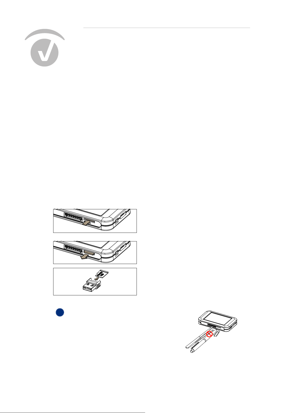
1 Switch off LiveAmp.
2 Push the memory card slightly into the slot to
unlock it from the holder.
The card will pop out.
3 Pull the memory card from the slot.
Î Insert the memory card into the USB reader
and plug the unit into your computer.
Alternatively, use the memory card adapter.
NOTICE
Damage to connectors when using tools
If you use tools, for example to remove the memory
card, you can accidentally touch the pins of the connectors. This causes damage to LiveAmp.
Do not use tools to remove or insert the memory card.

9 Accessing your data 54
Download the data to a computer
Make a copy of your data on your computer for analyzing and as a back-up.
Prepare
- USB card reader or memory card adapter
1 Eject the memory card
from LiveAmp.
2 On your computer, open the memory card.
For example, by clicking on: Windows Explorer > Com-
puter > Removable Disk.
Î You can now copy the data from the memory card to
your computer.
Files on the memory card
LiveAmp 8, 16 and 32
LiveAmp 8, 16 and 32 saves the EEG data and the settings of the Recorder workspace on the memory
card. These files have following names and extensions:
Workspace: TEMP.WSP
EEG, bipolar and trigger data: LA000001.DAT (the digit is automatically incremented)
LiveAmp 64
LiveAmp 64 saves the EEG data and the settings of the Recorder workspace on the memory cards of
each LiveAmp 32. When using the LiveAmp 64 you will have to copy the files from the memory cards
of both LiveAmps (.DAS and .MAS) to the same folder as both files are required for compilation by
File Converter.
These files have following names and extensions:
Workspace: TEMP.WSP
Master LiveAmp - EEG and trigger data: LA000001.DAM (the digit is automatically incremented)
Slave LiveAmp - EEG, bipolar and trigger data: LA000001.DAS (the digit is automatically incre-
mented)

9 Accessing your data 55
NEW
9.2 Convert the data
After the data acquisition, use the LiveAmp File Converter to convert the data from the memory card.
When using the LiveAmp 64 you will have to copy the files from the memory cards of
both LiveAmps (.DAS and .MAS) to the same folder as both files are required for compilation by File Converter.
The TEMP.WSP file does not have to be copied for any version of LiveAmp.
Prepare
- Computer with BrainVision LiveAmp File Converter
- Memory card inserted into recording computer
1 Open the LiveAmp File Converter.
Windows start button > All Programs > BrainVision > BrainVision LiveAmp File Converter.
2 Load the EEG files.
In the line ‘LiveAmp File’, click on Select and
locate the EEG data.
Search for the folder with your EEG data.
When using LiveAmp 64 it is essential that
files from both LiveAmps are copied to the
same folder.
3 Select the files for conversion. Select the
*.DAT file if using LiveAmp 8, 16, 32 or select
the *.DAM file if using LiveAmp 64:
Select a single file: Select the *.DAT or
*.DAM file, then click Open.
Select multiple files: Begin by selecting
the first *.DAT or *.DAM file, press and
hold the Ctrl key. While holding down the
Ctrl key select each of the other files you
want to convert. Click Open.
Select all files: Begin by selecting one
*.DAT or *.DAM file then press and hold
the Ctrl key and press A. Click Open.

9 Accessing your data 56
4 Specify the target file/folder.
a In the line ‘BrainVision Folder’ (multiple
files selected) or ‘BrainVision File’ (single
file selected), click Select.
b Select the target folder.
c If required, rename the folder and click
Open.
5 The status will update to display the number
of files selected for conversion.
Finally, click Convert.
6 The Result pane will display that status of the
file conversion and alert you to any issues encountered.
7 Check the conversion.
Open the target folder and make sure that
there is the EEG file (*.EEG), header file (*.VHDR) and marker file (*.VMRK).
Î The converted EEG files can now be used in
Analyzer.
9.3 Back-up the data of the memory card
Make a copy of the memory card to ensure that you still have the recordings in case the memory card
is lost or accidentally formatted.

9 Accessing your data 57
Prepare
- LiveAmp with memory card
- memory card adapter, or the USB adapter with USB cable
Method 1 - Copy data directly from the memory card
1 Switch off LiveAmp
2 Eject the memory card.
3 Insert the memory card into the USB card reader or adapter and plug the unit into your com-
puter.
4 Open the Windows Explorer.
5 In the Windows Explorer, click on Removable Disk.
6 Copy the files to a directory of your choice.
Method 2 - Copy data from memory card in LiveAmp
1 Connect LiveAmp to your computer by using the USB adapter.
2 Open the Windows Explorer.
3 In the Windows Explorer, click on Removable Disk.
4 Copy the files to a directory of your choice.
Î The memory card is shown as Removable Disk in the Windows Explorer. You can open, add and
remove files from the memory card.
Note
We recommend to use Method 1, because it is faster.
9 Accessing your data 58
V
9.4 Format the memory card
Recorder prompts you to format the memory card, when it is full or fragmented.
Notes
- You must use the formatting function in Recorder to format the memory card. Do
not use the Windows function to format the memory card.
- Back-up the data, before formatting the memory card (see 9.3 Back-up the data
of the memory card). Otherwise your data are lost.
Prepare
- LiveAmp with memory card
-Recorder
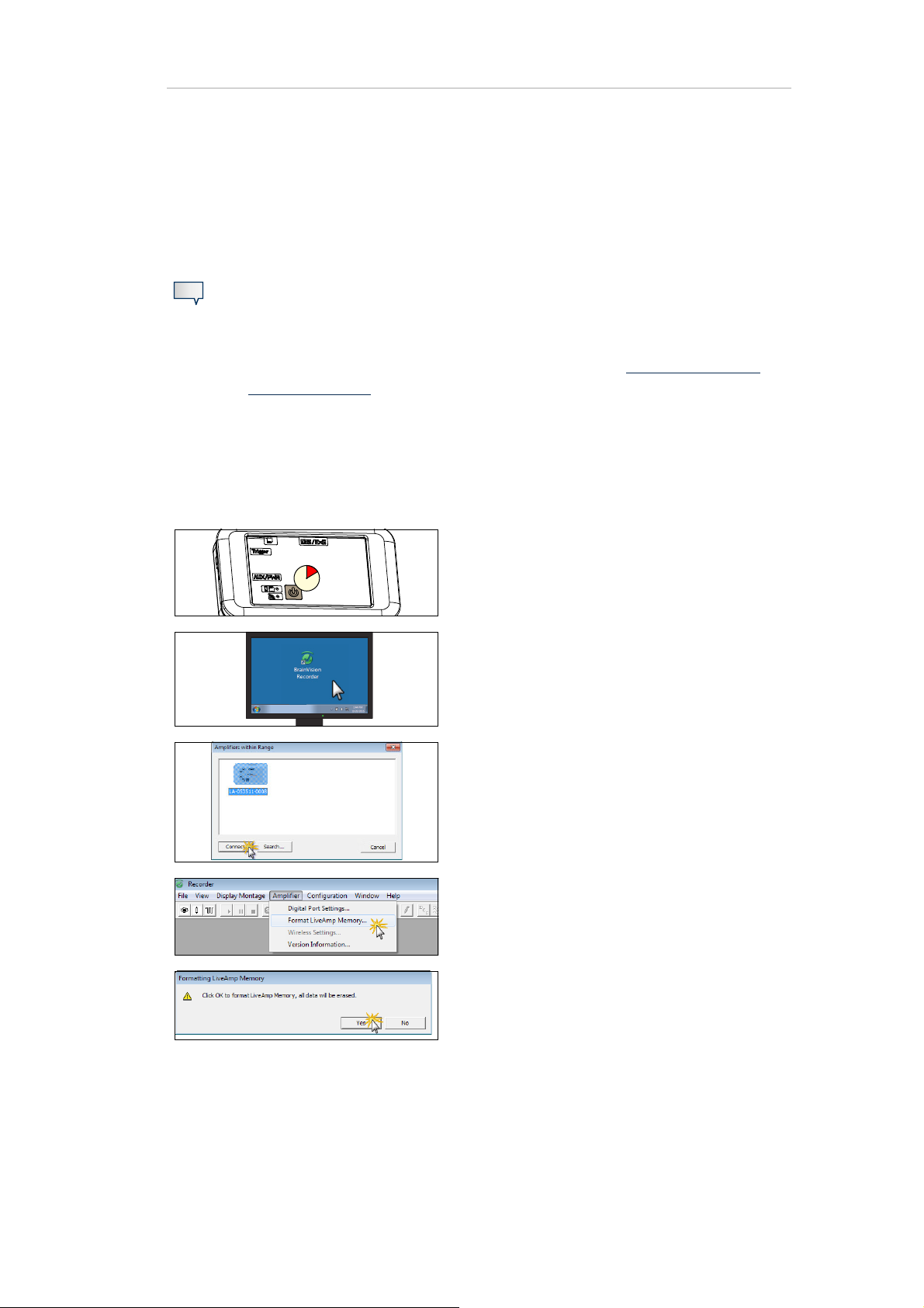
1 Switch on LiveAmp.
2 Start Recorder.
3 Connect LiveAmp with Recorder (wireless).
4 In the Recorder main window, click on Ampli-
fier > Format LiveAmp Memory...
5 Confirm the notification message.
Î The memory card in LiveAmp is formatted and
all data on the memory card is deleted. When
formatting LiveAmp 64 both memory cards
will have their data deleted.

9 Accessing your data 59z60

10 After using LiveAmp
!
10.1 Clean LiveAmp and the accessories
NOTICE
Risk of damage during cleaning.
Don’t clean the products and accessories under running water.
Don’t use aggressive or corrosive cleaning agents and don’t sterilize the product.
Don’t use hot liquids. The temperature of liquids must not exceed 40 °C (104 °F).
Before cleaning disconnect all cables. Connectors must not come into contact with moisture. Moisture causes corrosion.
Clean the products with a slightly damp cloth.
Using a disinfectant
For disinfecting the surfaces of the products, we recommend to use a cleaning agent based on propylalcohol, for example a solution containing 25 % Ethanol and 35 % Propane-1-ol. Adhere to the
safety precautions of the manufacturer of the cleaning agent.
10.2 Clean the electrode cap
Detailed cleaning instructions are described in the following manuals, that are all available on the Application Suite USB:
active electrodes: actiCAP Operating Instructions and actiCAP slim electrode Operat-
ing Instructions
passive electrodes: BrainAmp Operating and Reference Manual for use in a laborato-
ry environment

10.3 Charge the battery of LiveAmp
After each use, fully charge the battery of LiveAmp.
Prepare:
- LiveAmp amplifier
- USB cable (15 cm)
- USB adapter
- USB charger or computer with USB port
1 Connect the USB adapter to LiveAmp.
10 After using LiveAmp 61
2 Connect the USB cable to the USB adapter.
3 Connect the USB cable to the USB charger,
and plug the charger into the power socket.
Alternatively, connect the USB cable to an
USB port of your computer.
Î The battery LED blinks green, when LiveAmp is
charging.
When LiveAmp is connected with Recorder,
the battery icon in the status bar blinks.
10.4 Charge the power bank
After each use, fully charge the power bank.
To charge the power bank follow the operating instructions of the manufacturer of the power bank.
z

11 Maintenance, disposal and updates
11.1 Maintenance information
LiveAmp requires no maintenance. Repairs may only be carried out by Brain Products. Regularly inspect the products and accessories for damage and check that the connections are clean. In the
event of any defects, please contact your local dealer.
62
11.2 Disposal information
CAUTION
Risk of burns by disassembling LiveAmp
By opening LiveAmp the battery can be damaged. When a Lithium-Ion battery is damaged, it can catch fire and cause burns. Only trained personnel may open and disassemble LiveAmp.
Do not open or disassemble LiveAmp and its accessories.
Do not dispose of products, accessories and cables with the household waste. Dispose of them in
accordance with national regulations or return the product and its accessories to the manufacturer.
For example, in the EU and EFTA, the Directive on Waste Electrical and Electronic Equipment (WEEE)
applies.
11 Maintenance, disposal and updates 63
11.3 Update the firmware of LiveAmp
If there is a firmware update for LiveAmp you will be notified by e-mail, through a newsletter or by
your distributor. Firmware updates can enhance the performance of LiveAmp. Therefore, install an
update whenever it is available.
Prepare
-LiveAmp
- USB adapter with USB cable
- computer with Internet connection
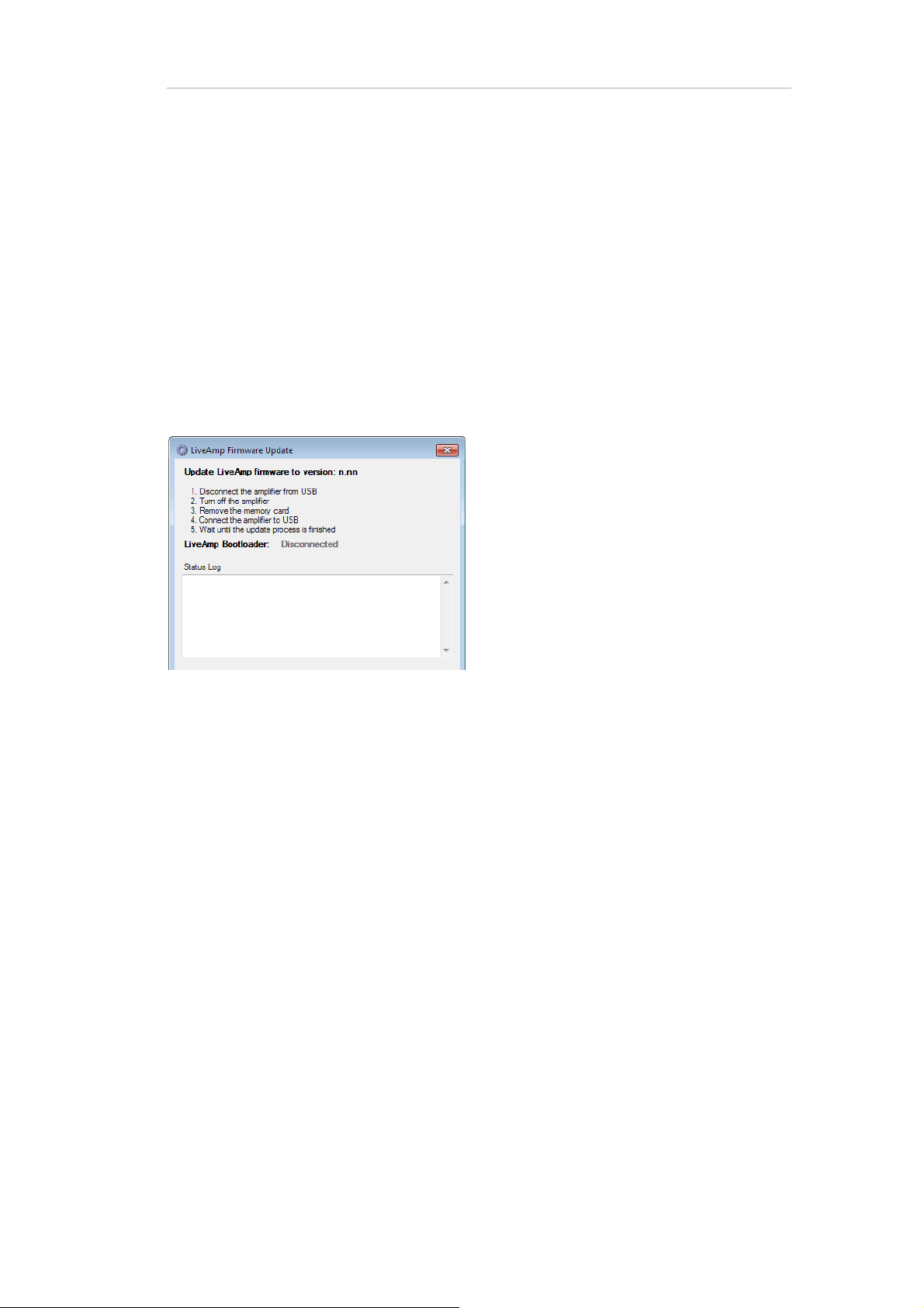
1 Download the firmware update from the Brain
Products website or contact your local distributor.
2 Start the updater.
3 Follow the instructions on the screen.
Î During the update, the battery LED of LiveAmp
flashes green.
z

12 Troubleshooting
12.1 Knowing the status of LiveAmp
You can determine the operating status of LiveAmp by the LEDs and in the recording software.
64
1 Battery/recording LED
Different colors indicate the battery state from green (= full) to red (= empty).
OFF LiveAmp is OFF.
ON LiveAmp is ON (any color),
Charging completed (green) when connected to a power source
blinking slow, green LiveAmp is charging.
blinking fast, any color Recording to memory card
2 Wireless LED
This LED is blue.
OFF Wireless module is OFF.
ON Wireless module is ON, but LiveAmp is not connected with Recorder.
blinking LiveAmp is connected with Recorder.
Is my LiveAmp charging? (see page 70)

12 Troubleshooting 65
12.2 Troubleshooting charts Issues with LiveAmp
Note
Before you begin troubleshooting, check the log files for LiveAmp. You can find the
log files on your local drive. By default they are stored under:
C:\Vision\Recorder\Log.
Symptom Possible cause Remedy
Cannot switch on LiveAmp Battery empty. Charge the battery of LiveAmp.
Make sure that you have the
Cannot attach cap to LiveAmp Cap with wrong connector.
correct cap (see 1 Scope of
delivery).
Recorder does not find my
LiveAmp
Wireless LED switches off
during recording.
LiveAmp switched off during
recording
No wireless adapter connected.
LiveAmp out of wireless range.
LiveAmp not switched on.
LiveAmp connected with
another computer (wireless
LED blinks blue).
The wireless module turns off
one minute after LiveAmp is
out of range or was disconnected from the recording
computer.
Battery is empty.
I/O button was pressed for 5
seconds or longer.
Connect the wireless adapter
UBT21.
Get LiveAmp closer to the wireless adapter.
Switch on LiveAmp. The battery/recording LED is ON and
lights green and blue LED is on
and lights blue.
Disconnect LiveAmp on the
other computer and search
again.
Press the I/O button for 1 second to switch on the wireless
module.
Charge the battery. When the
battery LED is red, the remaining recording time is approximately three minutes.
The EEG data that was
recorded until LiveAmp was
switched off is still usable.
Cannot find LiveAmp in Win-
®
dows
LiveAmp connected wireless
AND via USB adapter to the
computer.
Press and hold the I/O button
for at least 5 seconds to switch
off the wireless adapter.

12.3 Issues with LiveAmp 64
Symptom Possible cause Remedy
12 Troubleshooting 66
LiveAmp 64 not recognized.
LiveAmp 64 not discovered by
Recorder.
Lost samples when recording.
Recorder does not recognize
the Sensor trigger extension
when connected to LiveAmp
64.
LiveAmp 64 is not discovered
by Recorder.
Only one wireless adapter
plugged in.
Incompatible firmware versions used on one or both of
the LiveAmp’s.
Wireless adapters are too
close to each other
Sensor trigger extension has
been plugged in after LiveAmp
was connected to Recorder.
Both LiveAmps are on but not
connected.
Connect a second wireless
adapter.
Ensure both LiveAmp’s are
running firmware version 4.59
or later.
Separate the wireless adapters by at least 50cm.
Disconnect and reconnect
LiveAmp to Recorder.
Connect LiveAmps to connector for active electrodes or to
cap with passive electrodes.
12.4 Battery / Charging issues
Symptom Possible cause Remedy
Connect LiveAmp to the proBattery LED blinks amber while
charging
Power source too weak
vided USB charger or a power
bank. (The provided charging
current must be 500 mA.)

Battery was not fully charged.
12 Troubleshooting 67
Fully charge the battery. It
takes around 4 hours to
charge an empty battery. If the
charging time seems to be too
short, fully discharge LiveAmp
and charge it again.
Battery discharges too quickly
Battery does not charge OR
Battery does not charge fully
Too long in impedance mode
with active electrodes.
Note: Impedance measurement of active electrodes consumes a lot of battery power.
USB adapter not plugged in
correctly.
Connect LiveAmp with the
USB adapter to a power
source during impedance
measurement in order to
save battery power.
Start the impedance mea-
surement after preparing
the cap.
Make sure that the USB
adapter is plugged in correctly
on both ends (LiveAmp and
power socket).
If the issue remains, contact
your local distributor.

12.5 Lost samples
Symptom Possible cause Remedy
Only use the micro memory
Wrong card type.
Lost samples on memory card
Memory card is not formatted
with Recorder.
card as specified by Brain
Products GmbH.
Use Recorder to format the
memory card.
12 Troubleshooting 68
Lost samples during recording
(lost sample markers)
Wireless adapter (UBT21) not
used.
Other wireless devices in
range.
Too far away from recording
computer.
Too many channels for
selected sampling rate.
Use the wireless adapter
UBT21 that is in the scope of
delivery.
Make sure, that there are no
interferences with other wire-
less devices. For example,
®
switch off Bluetooth
of your
mobile phone.
Get closer to the wireless
adapter, to improve the signal
strength.
If you selected more than 24
channels at a sampling rate of
1,000 Hz, lost samples might
appear on the recording com-
puter. Do one of the following:
get closer to the recording
computer.
record to the memory card
(no samples are lost when
recording to the memory
card).
reduce the number of chan-
nels.
reduce the sampling rate.
12.6 Issues related to the physiological signals
Symptom Possible cause Remedy

12 Troubleshooting 69
No signals in Recorder
Noise on all channels
Flat lines for Auxiliary channels and marker.
Electrode connector not connected correctly.
LiveAmp is out of range.
Check if the electrode connec-
tor snaps into the LiveAmp.
Move closer to the wireless
adapter.
Electrode input broken. Contact your local distributor.
LiveAmp with the Sensor and
trigger extension and a power
actiCAP Xpress Twist is used
and a power bank connected.
bank should not be used with
actiCAP Xpress Twist. The
noise of dry electrodes will
increase significantly under
these operating conditions.
Battery empty/battery not connected.
Sensor and trigger extension
Charge battery or connect
extension battery.
not connected.

12.7 Analyzer problems
NEW
Symptom Possible cause Remedy
12 Troubleshooting 70
Cannot open data in Analyzer EEG data was not converted.
Refer to Section 9.2
verting data.
12.8 Sensor and trigger extension issues
Symptom Possible cause Remedy
Recorder does not recognize
the sensor trigger extension
box.
Battery not connected to the
sensor trigger extension box.
Connect battery.
12.9 Frequently asked questions
for con-
Is my LiveAmp charging?
When LiveAmp is connected to a power source you can determine the status by the LED or in the recording software:
Your LiveAmp is charging:
when the Battery LED blinks slowly
OR
when connected with Recorder and the battery icon in the
status bar of Recorder blinks.
Note
You cannot determine on the LiveAmp if it is charging when it is acquiring data, in this
modus the battery/memory LED is not indicating the charge status but other states.

12 Troubleshooting 71
Where is my EEG data?
If you record to the memory card, then your data is stored on the memory card. To access the
data, see 9.2 Convert the data
When simultaneously recording to the memory card and computer, approximately the first ten
seconds on the memory card will be missing. This is due to LiveAmp preparing the memory card
when a recording is started.
.
LiveAmp was switched off during the recording. Is my EEG data lost?
No. The EEG-files on the recording computer and memory card contain the data until LiveAmp was
switched off.
Can I use the Bluetooth® adapter of my computer?
We recommend you use the provided wireless adapters (UBT21) to ensure reliable
data transmission. When using LiveAmp 64 one wireless adapter (UBT21) should remain connected.
By default, Recorder uses the wireless adapter UBT21. To use the internal adapter of your computer
instead, do the following:
1 Start Recorder (no amplifier connected).
2 Click on Amplifier > Wireless Settings...
3 The Wireless Settings window opens.
4 Select the check box and click OK.
Î You can now use the internal wireless adapter of your
computer.
I lost my memory card. Can I record data?
Yes, but only to the recording computer. If you want to record data to LiveAmp you must insert the
supplied memory card into LiveAmp.

Only use memory cards, that match the specifications:
Card type: micro memory card, class 10
Size: 32 GB
12 Troubleshooting 72
z

Appendix A Technical data
Ambient conditions
Charging (LiveAmp) Temperature: 10 °C to 30 °C (50 °F to 86 °F)
Operation Temperature: 10 °C to 40 °C (50 °F to 104 °F)
Relative humidity: 25 % to 85 %, non-condensing
Atmospheric pressure: 700 hPa to 1,050 hPa
Storage and transport Temperature: 0 °C to 40 °C (32 °F to 104 °F)
Relative humidity: 45 % to 85 %, non-condensing
Atmospheric pressure: 700 hPa to 1,050 hPa
73
To prevent mechanical damage during transport, please pack the product in such a way, that it is
not subject to vibration.

Technical data of LiveAmp
EEG/ExG channels
Appendix A Technical data 74
Number/type of channels
LiveAmp 8 channel
LiveAmp 8 can record a total of 8 channels, unipolar and/or
bipolar.
LiveAmp 16 channel
LiveAmp 16 can record a total of 16 unipolar channels with a
maximum of 8 bipolar channels or 8 unipolar and 8 bipolar
channels.
LiveAmp 32 channel
LiveAmp 32 can record either 32 unipolar channels or 24 unipolar
and 8 bipolar channels.
LiveAmp 64 channel
LiveAmp 64 can recorder either 64 unipolar channels or 56
unipolar and 8 bipolar channels.
Measurement range ±341.6 mV
Gain factor 12
Input noise < 2 μV
(0.01 Hz to 65 Hz at 250 Hz sampling rate)
pp
measured with internal battery and shorted inputs
Input impedance > 200 MOhm (at DC)
impedance of EEG/ExG channels to GND
Differential input impedance
> 400 MOhm (at DC)
impedance between two EEG/ExG channels or bipolar EEG/ExG
channels
Common-mode rejection
> 80 dB (at 50/60 Hz)
(CMR)
Signal coupling DC (there is no high pass filter in amplifier hardware)
Low pass filter in amplifier Third order sinc filter with -3 dB frequency depending on the sam-
ple rate:
1,000 Hz: 262 Hz
500 Hz: 131 Hz
250 Hz: 65 Hz
A/D conversion 24 bit
Resolution
Approx. 40.7 nV / bit (= 2*341.6 mV / 2
24
bit)
Acceleration sensor Built-in 3-axis acceleration sensor
Three separate channels (x, y, z)
Measurement range: ±2 g
Resolution: 1 mg/bit, 12 bit
Error: ±0.2 g (±10 % of full scale)

Appendix A Technical data 75
Select between 250 Hz, 500 Hz and 1,000 Hz.
Note: Maximum wireless bandwidth cannot always be guaranteed due to external interference.
Hardware Sampling Rates
Data Storage
Data storage
Card type
On recording computer via wireless transmission
On micro memory card
On recording computer and on micro memory card
micro SD
Size of memory card 32 GB
Maximum file size on mem-
4GB
ory card
Data format on internal
memory card
Proprietary format; can be converted to generic Brain Products data
format with converter software provided by Brain Products
Sampling Rate EEG/ExG channels
1000Hz
500Hz
®
card, class 10
Up to 32 channels
(this incl. AUX and acceleration)
32 channels or more
(this incl. AUX and acceleration)
Wireless transmission
Wireless data transmission In 2.402-2.480 GHz ISM band
worldwide no restrictions for using this ISM range
Radio frequency output power Max. 13 dBm (approx. 20 mW)
Wireless transmission range Indoor: Up to 10 m (depending on environment)
Outdoor: Up to 30 m
Electrodes
Compatible electrodes
Passive Ag/AgCl based electrodes
Active actiCAP electrodes
Impedance measurement Available for passive and active electrodes and inte-
grated in amplifier.
Impedance measurement range Up to 500 kOhm

Appendix A Technical data 76
Battery and power supply
Power supply Built-in rechargeable battery
Capacity: 1,000 mAh.
Current consumption Max. 250 mA
Charging time Approx. 4 hours at 500 mA (for example, USB port of a computer)
Uninterrupted recording
time with built-in battery
(when fully charged)
> 3 hours (wireless data transfer only and passive electrodes)
> 4.5 hours (storage on memory card only and passive electrodes)
Further data
Built-in trigger/marker input Yes, 3-pin 2.5 mm phone jack; TTL compatible; active low
LED indicators Battery/status LED: green, yellow, red
Wireless LED: blue
Dimensions (W x D x H) 83 mm x 51 mm x 14 mm
Weight Approx. 60 g (incl. built-in battery)
LiveAmp USB adapter
USB communication Data rate: 12 MBit/s
USB 2.0 compatible
Input and output voltage 5 V
Maximum power transfer 5 W
Galvanic isolation 2,500 VDC
Dimensions (W x D x H) 40 mm x 30 mm x 20 mm
Weight Approx. 30 g
Cable length Approx. 50 cm, not detachable
System requirements for the LiveAmp
Operating system Windows® 7, 32 and 64 bit
Windows® 8.1, 64 bit
Windows® 10
USB port USB 2.0 or higher
LiveAmp Firmware LiveAmp 64
Both LiveAmps should be running firmware version 4.60 or
later.

Appendix A Technical data 77
Software requirements
LiveAmp 32 channel
BrainVision Recorder version 1.21.0001 or later
LiveAmp 8 channel and LiveAmp 16 channel
BrainVision Recorder version 1.21.0201 or later
LiveAmp 64
BrainVision Recorder version 1.21.0303 or later

Appendix A Technical data 78
Pin assignment of LiveAmp
Electrode connector
Pin Function Pin Function Pin Function Pin Function
1 GND 16 In 27+ 31 In 23 46 In 16
2 MP1 17 VGND 32 In 24 47 In 13
3 MP2 18 In 27- 33 In 21 48 In 14
4 5 V 19 N 34 In 22 49 In 11
5 MP3 20 In 28+ 35 In 19 50 In 12
6 3 V 21 VGND 36 In 20 51 In 9
7 In 29+ 22 In 28- 37 In 17 52 In 10
8 In 29- 23 REF 38 In 18 53 In 7
9 In 30+ 24 NC 39 NC 54 In 8
10 In 30- 25 VGND 40 NC 55 In 5
11 In 31+ 26 NC 41 NC 56 In 6
12 In 31- 27 In 26+ 42 NC 57
In 3
13 In 32+ 28 In 26- 43 NC 58 In 4
14 In 32- 29 In 25+ 44 NC 59 In 1
15 NC 30 In 25- 45 In 15 60 In 2
GND = Ground
VGND = Virtual Ground
REF = Reference
IN = Input signal
MP = Multi-purpose
NC = Not Connected

Trigger connector (2.5-mm phone jack)
Pin Function
1 (tip) Not used
2 (ring) Trigger in
3 (sleeve) Ground (GND)
AUX connector
Pin Function
Appendix A Technical data 79
1USB D+
2USB D-
3NC
4I2C-SDA
5I2C-SCL
65V in
75V in
8GND
Shield Shield

Appendix A Technical data 80
Technical data of the sensor and trigger extension
Number of AUX channels 8
Input range of AUX channels ± 4.8 V
Current supply at AUX inputs Max. 80 mA in total (that is 1 x 80 mA or 8 x 10 mA or etc.)
Sample rate of AUX inputs The sampling rate is the same for all channels (LiveAmp and
Sensor and trigger extension). Regarding channel numbers and
sampling rates the same restrictions as mentioned for LiveAmp
apply (see above).
Galvanic isolation of AUX
inputs
Trigger input
Trigger output
Galvanic isolation of trigger
inputs and outputs
AUX channels are galvanically isolated from the EEG/ExG channels of LiveAmp (isolation voltage 1,500 VDC).
Number of bits: 8
Connector type: D-Sub, 9-pin, female
Low active (internal 10 kOhm pull-up resistor to Vcc)
TTL compatible
Number of bits: 8
Connector type: D-Sub, 9-pin, male
TTL compatible
Trigger channels are galvanically isolated from the EEG/ExG
channels of LiveAmp (isolation voltage 1,500 VDC / 1,080 VAC
(for 1 s)).
Current consumption Without sensors: 100 mA
With sensors: 100 mA plus the total current of the sensors
Dimensions (W x D x H) 11.7 cm x 7.6 cm x 3.0 cm
Weight < 130 g
Power supply From external battery pack (powerbank) via the galvanically iso-
lated LiveAmp USB adapter.
Length of cable to LiveAmp 80 cm (31 in.)
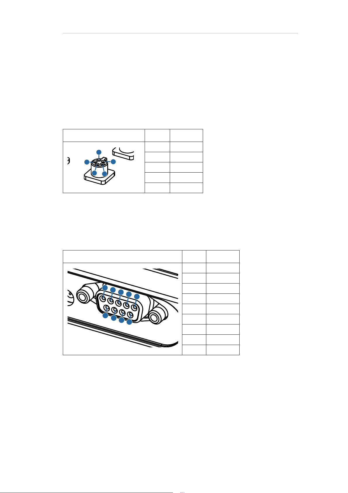
Appendix A Technical data 81
Pin assignment of the sensor and trigger extension
AUX sockets
Connector type: Binder 719/709, 5 pin, female
Pin Function
1+5 V
2ln+
3Ground
4ln-
5-5 V
Trigger in
Connector type: D-Sub, 9-pin, female
Pin Function
1Bit 1
2Bit 2
3Bit 3
4Bit 4
5Bit 5
6Bit 6
7Bit 7
8Bit 8
9 Ground

Trigger out
Connector type: D-Sub, 9-pin, male
Appendix A Technical data 82
Pin Function
1Bit 0
2Bit 1
3Bit 2
4Bit 3
5Bit 4
6Bit 5
7Bit 6
8Bit 7
9 Ground
z
 Loading...