

Brain Products BrainAmp MR Series, BrainAmp MR plus, BrainAmp ExG MR, BrainAmp MR Operating And Reference Manual

www.brainproducts.com
BrainAmp MR
For the models
BrainAmp MR
BrainAmp MR plus
BrainAmp ExG MR
Operating and Reference Manual
for use in an MR environment

BrainAmp MR | Operating and Reference Maual for use in an MR environment
Copy right
Any trademarks mentioned in this document are the protected property of their rightful owners.
The reproduction, distribution and utilization of this document as well as the communication of its contents to
others without express authorization is prohibited. Offenders will be held liable for the payment of damages. All
rights reserved in the event of the grant of a patent, utility model or design. Subject to change without notice.
For the latest version of this document, please visit www.brainproducts.com or contact your local distributor.
Published by Brain Products GmbH
Zeppelinstrasse 7
82205 Gilching
Germany
Published on* September 29. 2016 Document version 019
*Valid until publication of a new version of this document.
© 2016 Brain Products GmbH
Phone: +49 (0) 8105 733 84 - 0
Fax: +49 (0) 8105 733 84 - 505
Web: www.brainproducts.com

Contents
List of figures .................................................................................................................................................. 5
About this manual ........................................................................................................................................ 7
The structure of the manual ............................................................................................................................. 7
Who is the manual intended for? .................................................................................................................... 8
Conventions used in this manual .................................................................................................................... 8
Document revision history .............................................................................................................................. 9
Reporting errors and support .......................................................................................................................... 9
3
Acknowledgments ...................................................................................................................................... 11
Introduction ................................................................................................................................................ 13
Intended use ................................................................................................................................................. 14
Correct use .................................................................................................................................................... 14
Use together with other products and components ........................................................................................ 15
Chapter 1 Installation instructions for the conduct of combined EEG-fMRI measurements .............................. 17
1.1 Synchronizing the systems using the SyncBox ................................................................................ 17
1.2 Recording volume triggers (volume markers) using the trigger cable ............................................... 23
1.3 Conversion of optical trigger pulses ................................................................................................ 24
1.4 Functional test of the interfaces of the scanner and amplifier system .............................................. 25
Chapter 2 Preparing and operating the amplifier system in an MR environment ............................................... 27
2.1 Safety aspects of combined EEG-fMRI measurements .................................................................... 29
2.1.1 Recommended coil configuration for combined EEG-fMRI measurements (head transmitter coil vs. body
transmitter coil) ............................................................................................................................. 30
2.1.2 MR sequences and the safety of the test subject ............................................................................. 31
2.1.3 Protecting the amplifier in the MR environment ............................................................................... 33
2.2 Considerations on positioning the components for combined EEG-fMRI measurements .................. 35
2.3 Correct use of the connections to the amplifier from the test subject: BrainCap MR, electrode input box-
2.3.1 EEG recordings using the BrainCap MR ........................................................................................... 39
2.3.2 Electromyographic recordings (EMG-fMRI) ....................................................................................... 40
2.3.3 Electrocardiographic recordings (ECG-fMRI) .................................................................................... 42
BrainAmp MR Operating and Reference Manual for use in MR environment | Version 019 | September 29, 2016
es and MR electrodes ..................................................................................................................... 39

4
2.3.4 GSR-MR recordings (GSR-fMRI) ........................................................................................................ 45
2.4 Considerations on data quality for combined EEG-fMRI measurements ........................................... 47
2.5 Care and comfort of the test subject during combined EEG-fMRI measurements .............................. 50
2.6 Emergency measures ...................................................................................................................... 52
2.6.1 Emergency measures to release the test subject ............................................................................. 52
2.6.2 Measures in the event of an amplifier system malfunction or fault .................................................. 53
Appendix A Product identification ............................................................................................................................... 55
Appendix B Explanation of the markings on the products ........................................................................................ 57
Appendix C Phantom measurements in MR environments ....................................................................................... 59
Appendix D Using temperature measurements to verify that the study is set up safely ...................................... 61
Appendix E Guidelines on the safe conduct of combined EEG-fMRI measurements ............................................. 63
1 Head coil geometry ......................................................................................................................... 63
2 Further head coil characteristics .................................................................................................... 66
3 Stabilization of the test subject ...................................................................................................... 67
4 Sequences ...................................................................................................................................... 67
5 Static gradient field ....................................................................................................................... 68
6 Scanner types/manufacturers ........................................................................................................ 68
7 EEG amplifiers and accessories ..................................................................................................... 68
8 EEG cap .......................................................................................................................................... 79
9 Number of EEG channels ................................................................................................................. 79
10 Training of new personnel ............................................................................................................... 79
11 General rules of conduct ................................................................................................................ 80
12 Particular attention/supervision is required in the case of ............................................................. 80
Appendix F Elimination of errors and sources of interference ................................................................................. 81
Appendix G Recommended reading ............................................................................................................................ 83
General list of abbreviations ......................................................................................................................... 85
List of abbreviations for the cited MR sequences and methods .................................................................... 87
Subject index ............................................................................................................................................... 89

List of figures
Chapter 1 Installation instructions for the conduct of combined EEG-fMRI measurements
1-1 Connections between the SyncBox Main Unit, SyncBox Scanner Interface, amplifier and scanner 19
1-2 SyncBox Scanner Interface with cables connected (top view) 20
1-3 SyncBox Scanner Interface (side view), yellow "PWR" LED (left) and "Input" port for connection to the
scanner (right) 21
1-4 SyncBox Scanner Interface (side view), green "Signal" LED (left) and "Output" port for connection to
the SyncBox Main Unit (right) 21
1-5 SyncBox Main Unit with cables connected (top view) 21
1-6 SyncBox Main Unit (side view), "Input" port for connection to the SyncBox Scanner Interface (left) and
"AUX" socket for peripheral components (right) 22
5
1-7 SyncBox Main Unit (side view), "AUX" socket for connection to the USB2 Adapter (left) and "USB"
socket for connection to the computer (right) 22
1-8 "Sync On" markers and (example) volume markers in the EEG data (Recorder) 25
Chapter 2 Preparing and operating the amplifier system in an MR environment
2-1 Ribbon cable with burnt area caused by incorrect cable routing (loop) 29
2-2 Schematic representation of an RF field in a body RF coil 30
2-3 Schematic representation of an RF field in a local RF coil 30
2-4 Incorrect handling: burnt-out amplifier board due to open channels 33
2-5 Positioning of the amplifier and the PowerPack on the scanner table in a local RF transmitter coil (head
coil) 36
2-6 Positioning of the amplifier and the PowerPack on a platform in the scanner bore in a local RF trans-
mitter coil (head coil) 37
2-7 Body transmitter coil, positioning of the amplifier and the PowerPack behind the scanner bore on a
non-magnetic surface 38
2-8 Schematic representation of the correct way to position the BrainAmp ExG MR, PowerPack and ExG
AUX Box for a combined EMG-fMRI measurement on the limbs 41
2-9 Attaching the ECG electrode to the thorax 43
2-10 Attaching the ECG electrode to the back 44
2-11 GSR-MR module (top view) 45
2-12 GSR-MR module with connection to ExG AUX Box (side view) 45
2-13 GSR-MR module with connections for the GSR-MR electrodes (side view) 46
2-14 Configuration of the Recorder workspace 48
2-15 Clamps on the connection cables of the amplifier and cap 52
BrainAmp MR Operating and Reference Manual for use in MR environment | Version 019 | September 29, 2016

6 List of figures
Appendix A Product identification
Appendix B Explanation of the markings on the products
Appendix C Phantom measurements in MR environments
Appendix D Using temperature measurements to verify that the study is set up safely
D-1 Results of temperature measurement, Siemens TIM Trio with 12-channel head receiver coil and body
transmitter coil 62
Appendix E Guidelines on the safe conduct of combined EEG-fMRI measurements
E-1 Open head coil 63
E-2 Head coil adapted for EEG recordings 64
E-3 Head coil with side opening 65
E-4 Closed head coil 66
E-5 Stabilization of the test subject in the head coil 67
E-6 Positioning of the EEG amplifier at the head end of the scanner outside of the bore 69
E-7 Positioning of the EEG amplifier at the head end of the scanner inside the bore 69
E-8 Positioning of the ExG amplifier at the foot end of the scanner 70
E-9 Positioning of EEG and ExG amplifiers for parallel use 71
E-10 Taut, straight cable routing 71
E-11 No loops or kinks 71
E-12 Positioning of the EEG amplifier inside the scanner bore 72
E-13 Weighting down the EEG amplifier with sandbags 73
E-14 Positioning of the EEG amplifier and accessories for GSR-fMRI 74
E-15 Positioning of the GSR-MR module 74
E-16 Attachment of the GSR-MR electrodes 75
E-17 Positioning of the amplifier when the 3D Acceleration Module is used 76
E-18 Attachment of the EMG electrodes to the arm 77
E-19 Attachment of the EMG electrodes to the leg 77
E-20 Attachment of the ECG electrode 78
E-21 Attachment of the EOG electrode 79
Appendix F Elimination of errors and sources of interference
Appendix G Recommended reading

About this manual
This Manual describes how to use the BrainAmp MR, BrainAmp MR plus and BrainAmp ExG MR
amplifiers and their accessories1 in an MR environment.
The manual forms an integral part of the amplifier system. It must be precisely adhered to in
order to ensure that the amplifier system is used as intended (see the combined Operating and
Reference Manual for the BrainAmp and BrainAmp MR series of amplifiers) and operated correctly and to guarantee the concomitant safety of test subjects, users and third parties. Make
sure that this manual is always available to users.
The amplifiers are operated using the BrainVision Recorder recording software. You will find a
detailed description of the hardware functions that are fully software controlled (impedance
measurement, DC offset correction, configuration of the digital ports, setting of the resolution
and configuration of the filters) in the User Manual for the Recorder.
7
The structure of the manual
The BrainAmp MR Operating and Reference Manual describes the use of the amplifier system
in an MR environment:
Chapter 1 describes the installation steps that are required if you only want to perform
combined EEG-fMRI measurements.
You will find a detailed description of the additional installation steps that have to be performed in order to be able to operate the amplifiers in the BrainAmp Operating and Reference Manual for use in laboratory environment.
Chapter 2 contains stipulations on how to perform combined EEG-fMRI measurements
safely with the amplifier system.
Appendix C contains notes on how to perform phantom measurements.
Appendix D describes how to check the experimental setup using temperature measure-
ments.
In Appendix E, you will find guidelines intended to help you carry out your measurements.
Appendix F contains a list of the most frequent sources of problems and interference.
Appendix G contains a list of the recommended scientific literature.
Appendix B lists the markings applied to the products.
1. The amplifiers and the accessories supplied by Brain Products are referred to as the "amplifier system" below.
BrainAmp MR Operating and Reference Manual for use in MR environment | Version 019 | September 29, 2016

8 About this manual
Topics covered by the BrainAmp Operating and Reference
Manual for use in laboratory environment.
For further information on the following points, please refer to the BrainAmp Operating and Reference Manual for use in laboratory environment which is available for download from our web
site at http://www.brainproducts.com/downloads.php:
Intended use
Additional installation steps that you must perform in order to be able to operate the am-
plifiers of the BrainAmp MR series
Maintenance and disposal
Terms of warranty
Product identification, relevant standards and legal notes
Technical data and conditions of use
Pinouts
Ordering codes
Who is the manual intended for?
The current manual is intended for physicians, medical experts and users working in the field
of psychological and neurological research. If the system is to be used in an MR environment,
knowledge of how to perform MR measurements safely is vital.
Conventions used in this manual
This manual uses the following typographical conventions:
Italic Italic text is used to identify menus, menu commands, dialog boxes, options,
the names of files and folders and the labels on the products. Italic font is
also used to highlight portions of running text.
Underscore
The blue dot indicates the end of a chapter.
Underscored text indicates a cross-reference or a web address.

This manual also uses the following symbols to help you find your way around:
The Personal injury symbol indicates that incorrect use of the products may
result in a health hazard to the test subject, the user and/or a third-party. Incorrect use means non-adherence to the stipulations set out in this manual.
The Damage to property symbol indicates that the incorrect use of the products may bring about a risk of damage to property.
The Stop symbol indicates that you should not carry out a particular action.
A note draws your attention to important (technical) information.
9
A cross-reference refers to another section or an external document that has
a bearing on the running text at this point.
A tip gives you advice, recommends a particular approach or draws your attention to an interesting aspect.
Document revision history
57 modified Markings on the product (NRTL discontinued)
Reporting errors and support
We would ask you to report to us without delay any error you find in this manual, any fault in
the products or any malfunction that you observe when operating the products and any event
where a test subject, user or third party has been injured, however slightly, or could have been
injured. To do so, contact your dealer who can also advise you about general questions relating
to these products.

10

Acknowledgments
At this point, we should like to extend our very sincere thanks to Dr. David Carmichael (University College London) and Dr. Helmut Laufs (Johann Wolfgang Goethe-Universität Frankfurt am
Main) for their careful review of these Operating Instructions, their constructive comments and
valuable scientific expertise.
We should also like to thank Dr. Robert Störmer (Brain Products GmbH) for his commitment
and for contributing his expert knowledge during the authoring of these Operating Instructions
as well as Ms. Katja Wust (Brain Products GmbH) who handled the editorial aspects involved
in their production.
Finally, we should also like to thank our translators, Phil White and Tim Pownall, for their excellent work.
11
Alexander Svojanovsky,
General Manager, Brain Products GmbH
BrainAmp MR Operating and Reference Manual for use in MR environment | Version 019 | September 29, 2016

12

Introduction
The BrainAmp MR, BrainAmp MR plus and BrainAmp ExG MR amplifiers are easy to use, compact and robust. Together with their accessories, the amplifiers form a complete, integrated
system. When used correctly, according to its intended purpose, the amplifier system guarantees excellent data quality and the very highest level of comfort and safety for users and test
subjects alike.
When our BrainAmp MR series of amplifiers was launched in 2000, it undoubtedly represented
a technical milestone. Over the years, combined measurement of EEG and MR data became increasingly widespread in the field of neurophysiological research. Initially the domain of a few
very technically oriented specialists who were implementing niche applications with the amplifier system, combined EEG-fMRI measurements now rank among the established methods
in the fields of neurophysiology and psychophysiology. A large number of neuroscientists are
successfully using laboratory paradigms in an MR environment and MR specialists are leveraging the value of the primary MR applications by the addition of electrophysiological measurements. The current manual has been written for this target group.
13
This manual is the result of many years of experience in using our amplifier system professionally. They reflect the dramatic changes that have affected MR technology over the past years.
The use of body transmitter coils in place of head transmitter coils and the use of ever greater
field strengths are but two examples. The manual therefore not only describes the functions
and use of the components that make up the complete system. It is, above all, also intended
to provide users with safety guidelines for preparing and performing combined measurements
in MR scanners.
For notes on the intended use of the amplifier system, please refer to the BrainAmp Operating
and Reference Manual for use in laboratory environment which is available for download from
our web site under the following link: http://www.brainproducts.com/downloads.php.
BrainAmp MR Operating and Reference Manual for use in MR environment | Version 019 | September 29, 2016

14
Intended use
The components of the BrainAmp family are intended to be used for acquiring neuro-/electrophysiological signals (e.g. EEG, EMG, ECG, EOG or signals from other approved sensors) in the
context of non-medical applications in order to carry out fundamental or applied research on
the basis of neurophysiological methodology and data.
In particular, the acquisition of invasive EEG signals is permitted if
the acquisition is performed outside the MR environment,
the BrainAmp components are powered by the PowerPack (rechargeable battery),
no other product is electrically connected with the test subject at the same time, and
no simultaneous electrical stimulation is used.
Invasive electrodes must not be used for recording ECG signals and polygraphic signals with
the BrainAmp components.
The components of the BrainAmp family are not medical devices. Use for diagnosis, therapy,
monitoring of vital physiological processes (such as cardiovascular functions) or other medical
purposes is expressly forbidden.
Correct use
The components of the BrainAmp family are permitted to be used by users in the psychological
and neurophysiological research area as well as physicians and medical experts for non-medical applications.
The components of the BrainAmp family are not permitted to be used by unqualified persons
(e.g. laymen), persons who cannot read (e.g. due to visual impairment) or understand (e.g. due
to a lack of language skills) the manual.
The components of the BrainAmp family are permitted to be used in the following environments: hospitals, clinics, other medical environments, research institutes and other non-medical environments (e.g. at home), provided that all the other stipulations regarding the correct
use are met and that the products are used in accordance with its intended use.
The components of the BrainAmp family are not permitted to be used in the following environments:
vicinity of explosive gases as may be the case in operating theaters, for example,
oxygen enriched atmospheres,

underwater (e.g. sea, swimming pool, bath tub) or in environments in which significant
amounts of water could enter the components of the BrainAmp family (e.g. under shower,
under water-tap).
The components of the BrainAmp family are permitted to be used for healthy and sick adults,
children and animals.
Irrespective of any liability on the part of the manufacturer, the relevant national stipulations
for operators and other relevant national legislation must be observed.
The user is solely liable for any risks to subjects associated with the investigation, if the product is not used in accordance with the correct use described.
15
Use together with other products and components
The components of the BrainAmp family may be combined with the following products and
components:
For use in and outside of MR scanner rooms:
Product Manufacturer
GSR-MR Module Brain Products GmbH
RespirationBelt MR Brain Products GmbH
3D Acceleration Sensor Brain Products GmbH
ExG AUX Box Easy Cap GmbH
BrainCap MR
(passive Ag/AgCl EEG electrodes/caps for MRI)
Electrode gel or paste Easy Cap GmbH
MR scanner
a. MR scanner room only.
a
Easy Cap GmbH
(others on request)
Siemens, GE, Philips, Bruker

16
Not for use in MR scanner rooms
Product Manufacturer
Passive Ag/AgCl EEG electrodes/caps that are not designed for
use in MRI (e.g. Multitrodes/BrainCap)
EasyCap GmbH
(others on request)
actiCAP active EEG electrodes (incl. SplitterBox and ControlBox) Brain Products GmbH
Electrode Input Box EIB 64 (32 and 64 referential channels) Easy Cap GmbH
ExG Input Boxes (with 16 bipolar ExG channels) Easy Cap GmbH
MOVE (transmitter and receiver) Brain Products GmbH
StimTrak Brain Products GmbH
Temperature sensor Becker Meditec
TriggerBox & TriggerBox Extension Brain Products GmbH
Photo sensor Brain Products GmbH
Respiration Belt Brain Products GmbH
Software (on a computer [not to be located in MR scanner room])
Product Manufacturer
BrainVision Recorder Brain Products GmbH
BrainVision RecView Brain Products GmbH
actiCAP ControlSoftware Brain Products GmbH
Requirements to the computer (not to be located in MR scanner room)
The computer to which you connect the amplifier (via the USB adapter) must fulfill the IEC
60950-1 or EN 60950.
In addition to this general overview of the permitted combinations, users must also check that
all the conditions applicable to the product in question (e.g. relating to MR compatibility) are
fulfilled for the specific combination and specific application (definition of purpose and intended use).
If users combine products other than those listed here then they are responsible for ensuring
the safety of test subjects, operating personnel and the environment. If the product data does
not immediately make it clear that products can be combined (connected) without danger then
the user must contact the relevant manufacturers to ensure that the required safety of all the
products involved is not compromised by the intended connection.

Chapter 1 Installation instructions for the conduct of combined EEG-
fMRI measurements
This chapter describes the installation steps that are required if you only want to perform combined EEG-fMRI measurements. These mainly relate to the establishment of the interfaces to
the scanner. On the one hand, these interfaces synchronize the systems using the SyncBox
and, on the other, serve to allow simultaneous recording of volume triggers provided by the
scanner.
You will find a detailed description of the additional installation steps that have to be performed in order to be able to operate the amplifier system in the BrainAmp Operating and Reference Manual for use in laboratory environment. (This also indicates the installation
procedure to be followed if you only want to use your MR amplifier under laboratory conditions.) This is available for download from our web site at http://www.brainproducts.com/
downloads.php.
The amplifiers are operated using the BrainVision Recorder recording software. Make sure that
the most recent version of the Recorder is installed on your computer. If you need it, the most
recent version can be downloaded from our web site under the link http://www.brainprod-
ucts.com/downloads.php.
17
1.1 Synchronizing the systems using the SyncBox
The SyncBox is used in order to synchronize the sampling rate of the amplifier with the scanner
clock system. The aim is to achieve phase synchronicity between the two clock systems. Only
in this way is it subsequently possible to achieve optimum correction of the artifacts in the EEG
data that are caused by the scanner.
The SyncBox system comprises the SyncBox Main Unit (see Figure 1-5 on page 21) and the SyncBox Scanner Interface (interface between the Main Unit and the MR scanner, see Figure 1-2 on
page 20).
The SyncBox Scanner Interface directly receives pulses coming from the scanner's gradient
clock board. It is equipped with two BNC connector plugs. (Siemens scanners do not use BNC
connectors and require a special adapter that is supplied with the SyncBox.)
The SyncBox system is not suitable for use in an MR environment. You must therefore
always use the SyncBox Main Unit and the SyncBox Scanner Interface outside the scanner room.
Always route the cables to the SyncBox Main Unit and the SyncBox Scanner Interface outside
the scanner room.
A physical connection must be established between the SyncBox Scanner Interface and a suitable clock signal output from the scanner in order to use the SyncBox.
You will find information on
the software configuration for
the SyncBox in the Recorder
User Manual.
The technical data for the
SyncBox can be found in the
BrainAmp Operating and Reference Manual for use in laboratory environment.
BrainAmp MR Operating and Reference Manual for use in MR environment | Version 019 | September 29, 2016

18 Chapter 1 Installation instructions for the conduct of combined EEG-fMRI measurements
The SyncBox Scanner Interface galvanically isolates the SyncBox Main Unit from the scanner
in order to prevent any negative impact on the scanner clock system. Nevertheless, as the op-
erator of the scanner, you must obtain the scanner manufacturer's official approval for establishing a connection of this type as well as approval of the selected clock signal output before
using the SyncBox system. Certificates from scanner manufacturers are available on request.
Installing the recording software
Connecting the SyncBox to the scanner and the amplifier
You require Version 1.10 or higher of the Recorder in order to operate the SyncBox system. If
this version is not installed on your computer, install the most recent version of the Recorder
before connecting the SyncBox to the computer.
It is neither necessary nor recommended that you connect the SyncBox Main Unit to the computer while you are installing the Recorder.
Proceed as follows to install the SyncBox system:
1 Connect the SyncBox Main Unit to the computer using the USB cable supplied.
Note that your computer must be equipped with a USB 2.0 port. The SyncBox will not function with a USB 1.0 or USB 1.1 port.
2 The computer detects the SyncBox using the Windows® plug-&-play function and informs
you that it has detected a new hardware component.
3 Allow the installation program to search for a suitable driver, which is located in the folder
C:\Windows\System32\Setup\Brain Products\BrainAmp\.
4 The driver is installed automatically.
Note that Windows® requires that the driver is re-installed for each USB port the first time
that the SyncBox is used on a different port.
Figure 1-1
shows a diagram of the connections between the SyncBox Main Unit, SyncBox Scan-
ner Interface, amplifier and scanner.

Synchronizing the systems using the SyncBox 19
Figure 1-1. Connections between the SyncBox Main Unit, SyncBox Scanner Interface, amplifier and scanner

20 Chapter 1 Installation instructions for the conduct of combined EEG-fMRI measurements
You will also find instructions
for connecting the SyncBox
on our web site at http://
www.brainproducts.com/
downloads.php ("How to SetUp the SyncBox").
The SyncBox is supplied with a short and a long 50 Ohm coaxial cable that you can use to connect the SyncBox system to the scanner. Proceed as follows:
1 Connect one end of the short 50 Ohm coaxial cable to the clock signal output of the scan-
ner.
2 Connect the other end of the short 50 Ohm coaxial cable to the Input port of the SyncBox
Scanner Interface (see Figure 1-3
).
3 Connect one end of the long 50 Ohm coaxial cable to the Output port of the SyncBox Scan-
ner Interface (see Figure 1-4).
4 Connect the other end of the long 50 Ohm coaxial cable to the Input port of the SyncBox
Main Unit (see Figure 1-6
).
When the connection to the SyncBox Main Unit is established, the PWR LED on the Output
port of the SyncBox Scanner Interface lights up green. The SyncBox Scanner Interface is
now ready for operation.
5 The SyncBox Main Unit has a number of connectors on either side. Connect the BNC cable
from the SyncBox Scanner Interface to the 50 Ohm BNC connector labeled Input (see
Figure 1-6
).
Next to the BNC Input port, there is a 15-pin HD D-Sub output labeled AUX.
The Signal LED is also on this side of the SyncBox Main Unit. It lights up yellow when the
SyncBox Main Unit receives a signal from the SyncBox Scanner Interface.
6 On the other side of the SyncBox Main Unit there are two ports and the PWR LED (see
Figure 1-7
). The AUX port is the counterpart to the HD D-Sub output labeled AUX. Connect
this port to the AUX output of the USB2 Adapter using the supplied short cable with two 15-
pin HD D-Sub plugs. This connection is required for SyncBox operation since the SyncBox
Main Unit and SyncBox Scanner Interface are supplied with power via this cable. The clock
signal generated in the SyncBox Main Unit for the amplifier is also transferred to the USB2
Adapter via this cable.
7 Finally, connect the USB port of the SyncBox Main Unit (see Figure 1-7
) to the computer us-
ing the USB cable supplied.
Figure 1-2. SyncBox Scanner Interface with cables connected (top view)

Figure 1-3. SyncBox Scanner Interface (side view), yellow "PWR" LED (left) and "Input" port for
connection to the scanner (right)
Figure 1-4. SyncBox Scanner Interface (side view), green "Signal" LED (left) and "Output" port
for connection to the SyncBox Main Unit (right)
Synchronizing the systems using the SyncBox 21
Figure 1-5. SyncBox Main Unit with cables connected (top view)

22 Chapter 1 Installation instructions for the conduct of combined EEG-fMRI measurements
Figure 1-6. SyncBox Main Unit (side view), "Input" port for connection to the SyncBox Scanner
Interface (left) and "AUX" socket for peripheral components (right)
Figure 1-7. SyncBox Main Unit (side view), "AUX" socket for connection to the USB2 Adapter
(left) and "USB" socket for connection to the computer (right)

Recording volume triggers (volume markers) using the trigger cable 23
1.2 Recording volume triggers (volume markers) using the trigger cable
Subsequent correction of scanner artifacts is considerably facilitated if volume triggers (volume markers) are recorded together with the EEG data. Volume triggers identify the clock rate
of the scanning operation. They are generally supplied by the scanner hardware in the form of
electrical or optical pulses. The volume triggers are recorded as (volume) markers by the Recorder.
Note that toggle mode is not supported.
If the volume trigger is supplied as an electrical pulse (TTL), you can connect the supplied trigger cable directly to the volume trigger output of the scanner if the pulse length is sufficient (
200 μs at an amplifier sampling rate of 5 kHz). If the pulse length is not sufficient, you require
the trigger stretcher cable that stretches the signal to an adequate length.
>
If an optical pulse is supplied, it must be converted to an electrical pulse (see Section 1.3 on
page 24).
If no better solution is available to you, you can also record slice triggers in place of volume
triggers.

24 Chapter 1 Installation instructions for the conduct of combined EEG-fMRI measurements
1.3 Conversion of optical trigger pulses
If the scanner supplies an optical pulse rather than an electrical pulse, you must convert it to
an electrical pulse using a converter.
A converter such as this allows you to connect the trigger input of the USB2 Adapter to the optical volume trigger output of the scanner.
If you require a converter as part of your experimental setup, please contact our technical support team for detailed advice. You will find the contact details for our technical support team
on page 9
.

Functional test of the interfaces of the scanner and amplifier system 25
1.4 Functional test of the interfaces of the scanner and amplifier system
Before starting the measurement, check whether the two interfaces to the scanner (clock signal via SyncBox and volume trigger via trigger cable) are working properly. To do this, connect
a least one amplifier to the USB2 Adapter.
Note that it is necessary to connect the SyncBox to the scanner clock system in order to check
synchronization and triggering. It is not, however, necessary for the amplifier to be located in
the scanner room. Neither is it necessary to connect an electrode cap.
Clock synchronization is indicated on the SyncBox Scanner Interface (green Signal LED), and
"Sync On" markers are written in monitoring mode in the Recorder (see Figure 1-8
).
Start a functional sequence in order to check triggering. Volume markers are then written in
monitoring mode in the Recorder (see Figure 1-8
Figure 1-8. "Sync On" markers and (example) volume markers in the EEG data (Recorder)
).

26 Chapter 1 Installation instructions for the conduct of combined EEG-fMRI measurements

Chapter 2 Preparing and operating the amplifier system in an MR
environment
The most important goal of this chapter is to provide guidance on minimizing risks during combined EEG-fMRI measurements. The chapter also considers ways of achieving the best possible data quality.
Read the following safety regulations through thoroughly before you put the amplifier system
into operation in an MR environment. If damage is caused as a result of failure to follow indications given in the present manual, warranty claims become invalid. Brain Products shall under no circumstances be liable for injuries or damages arising from a failure to observe the
safety regulations laid down here.
The fundamental aspects of how to use the amplifier system are not dependent on a particular
scanner product line as all currently available MR scanners are based on the same physical
principles. We assume that you have a basic understanding of the physical principles underlying MR imaging. We also assume that you have experience in using EEG amplifiers and MR
scanners.
27
The safety regulations apply as soon as you have attached electrodes, electrode caps and/or
sensors to the test subject. If you use the scanner in a manner other than that envisaged here
(for instance if you use different sequences), you must detach the entire amplifier system (including the electrode cap, sensors and any other components that may be present) from the
test subject and remove it from the scanner room.
The safety regulations given here refer to combined EEG-fMRI measurements at field strengths
of 1.5 through 7 Tesla in scanners manufactured by Siemens, Philips and General Electric as
well as at field strengths of up to 4 Tesla in scanners manufactured by Bruker. If you wish to
perform combined measurements with higher field strengths or in scanners from other manufacturers, contact our technical support team for in-depth advice. You will find the contact details on page 9
EEG measurements in an MR environment are fundamentally different from EEG acquisition under laboratory conditions. The reasons for this are the strong magnetic fields (both static and
rapidly switching gradient fields) and the extremely strong radio frequency (RF) pulses that occur during the scanning operation.
Risks associated with MR imaging alone are covered by the safety information and regulations
for use laid down by the scanner manufacturer. These regulations do not, however, cover those
risks that arise from MR measurements performed in combination with other procedures or
equipment (such as pacemakers or other diagnostic procedures).
Physiological recordings (such as EEG) performed under regular conditions outside a scanner
can theoretically also expose the test subject to certain risks, in the same way as any examination procedure.
.
For information on using MR
sequences, refer to
Section 2.1.2 as of page 31
.
Simultaneous EEG-fMRI measurements involve a further category of risks arising from the combination of both procedures. Such risks are superadditive. Neither regulations for use from the
scanner manufacturers nor governmental regulations – such as FDA or ISO regulations regarding the specific absorption rate (SAR) and the strength of the magnetic field – nor the obser-
BrainAmp MR Operating and Reference Manual for use in MR environment | Version 019 | September 29, 2016

28 Chapter 2 Preparing and operating the amplifier system in an MR environment
vance of thresholds are able to cover these combined risks. All these safety regulations and
thresholds refer only to MR application scenarios alone.
In order to minimize the risks arising from the combination of EEG and MR procedures, it is necessary to consider in detail the way in which the two procedures interact.

2.1 Safety aspects of combined EEG-fMRI measurements
Safety aspects of combined EEG-fMRI measurements 29
In terms of safety, MR imaging and EEG recording exert a mutual influence on each other with
respect to
the safety of test subjects, users and third parties
the operational safety of the products used
The main risk during combined EEG-fMRI measurements is the increase in temperature of the
EEG components, cables, electrodes and sensors that are connected to or come into contact
with the test subject. This heating can occur because
electrophysiological signals are measured using conductive cables.
magnetic resonance imaging requires the use of strong electromagnetic fields and electri-
cal radio frequency pulses.
the electromagnetic fields generate high-frequency alternating currents in conductive ma-
terials as a result of induction.
The induced currents can become so strong that the temperature of cables and electrodes may
rise (see Figure 2-1
). This can cause pain to the test subject and in the worst case can lead to
burns to the skin and tissue.
Figure 2-1. Ribbon cable with burnt area caused by incorrect cable routing (loop)
For information on the mutual
influence of both procedures
in respect of data quality, refer to Section 2.4 as of
page 47.
The induced currents depend on the type and strength of the electromagnetic fields and on the
geometry of the cables with respect to the fields. The type and strength of the electromagnetic
fields depend primarily on the properties of the MR pulse sequence used (duty cycle, flip angle, frequency, specific absorption rate, etc.), the gradient switching and the employed RF
transmitter coil.

30 Chapter 2 Preparing and operating the amplifier system in an MR environment
2.1.1 Recommended coil configuration for combined EEG-fMRI measurements (head transmitter coil vs. body transmitter coil)
Selection of a suitable, EEG-friendly head coil is crucial to allow the combined EEG-fMRI measurement to be conducted safely and to ensure the highest possible quality of data.
Modern scanners typically offer two operating modes: The RF energy required is emitted either
along the entire body coil (body transmitter coil, see Figure 2-2) or by one or more local coils
(e.g. head transmitter coil, see Figure 2-3). If the head coil has no transmission capabilities,
the body coil is automatically used as the RF transmitter coil by default.
Figure 2-2. Schematic representation of an RF field in a body RF coil
Figure 2-3. Schematic representation of an RF field in a local RF coil
If a body coil is used as the RF transmitter coil, the equipment used for recording the EEG (electrode cap, sensors, cables, amplifier and power supply) are exposed to a considerably stronger
RF field. If, on the other hand, a local coil is used as the RF transmitter coil, only the electrodes
and cables are exposed to the RF field. The choice of RF transmitter coil is therefore a crucial
factory in determining the safety of your EEG-fMRI setup.

Safety aspects of combined EEG-fMRI measurements 31
We strongly recommend that a head transmitter coil should be used for combined EEG-fMRI
measurements.
Alongside the transmission properties of the head coil, the setup, installation and connection
of the components used for the EEG recording are of vital importance. One basic rule applies
to all types of electrically conductive cable (such as electrode or sensor leads, for example)
used in an MR environment, namely that they should never form loops, half-loops or kinks. Induced currents are very low in straight cables that run along the central Z axis (head-foot axis)
of the scanner. Routing the cables in this way is desirable both for reasons of safety and with
respect to the quality of the EEG data.
Recent head coils therefore often feature EEG ducts (General Electric, Philips) or they are split
horizontally and can in some cases be operated without the top part (Siemens) in order to ensure that EEG leads can be routed correctly. Head coils from other suppliers (Rapid Biomedical
GmbH) often already completely meet all the requirements for EEG recording.
Head coils which do not permit cables to be routed straight and taut (because they are closed
along the Z axis) should not be used for combined EEG-fMRI measurements.
This means that the safest coil configuration consists of the following elements:
The head coil is designed as the RF transmitter coil.
The head coil is open in the positive Z direction (head) or features suitable ducts for EEG
leads.
2.1.2 MR sequences and the safety of the test subject
One important safety-related parameter of combined EEG-fMRI measurements is the specific
absorption rate (SAR) of the MR sequence used. The SAR is a measure of the absorbed RF energy per unit of tissue mass and is specified in watts per kilogram (W/kg). The SAR depends on
the strength of the static gradient field, the imaging sequence parameters and the body mass
that is exposed to the RF field.
The factors that influence the SAR most are:
The SAR is proportional to the square of the field strength B
higher in scanners with high and very high field strengths.
. It is therefore significantly
0
Since the SAR is proportional to the square of the flip angle, 180° pulses release four times
the energy of 90° pulses. As a result, for example, Spin Echo EPI (SE-EPI) sequences release considerably more energy than Gradient Echo EPI (GRE-EPI) sequences.
If the duty cycle is high (i.e. a large number of RF pulses in a short time), the SAR increases
linearly.

32 Chapter 2 Preparing and operating the amplifier system in an MR environment
Even though the measurement of the SAR is of great importance, the SAR, considered in isolation, is in no way a measure of the safety of combined EEG-fMRI measurements. SAR estimates
vary between scanner manufacturers and scanner models (see Nitz et al.). Furthermore, they
do not take account of the local increase in the SAR generated by EEG components and accessories.
Our amplifier system was designed exclusively for combined EEG-fMRI measurements using
single-shot GRE-EPI BOLD sequences. Single-shot GRE-EPI BOLD sequences are among those
MR sequences that have an inherently low SAR:
They do not use flip angles > 90°.
They only use one excitation pulse per slice.
If you have questions on a particular sequence that you wish to use
for a combined EEG-fMRI measurement, contact your scanner manufacturer and/or our technical
support team.
They employ an acceptable duty cycle for typical imaging parameters.
All scanner manufacturers provide GRE-EPI sequences by default.
Only use sequences with an inherently low SAR if you wish to perform a structural scan. These
include: Magnetization Prepared Gradient Echo (MP-RAGE/Siemens, TFE/Philips, FSPGR/General Electric) and Spoiled Gradient Echo (FLASH/Siemens, T1-FFE/Philips, SPGR/General Elec-
tric).
You can use gradient echo sequences based on Localizer and Scout with a flip angle
< 90° be-
fore the start of the functional measurement.
As a general principle, the EPI sequences that you can use in the context of combined EEG-fMRI
measurements with our amplifier system must meet the following criteria:
Only one activation pulse per slice
Flip angle < 90°
Time of repetition > 2000 ms
No more than 25 slices per 2000 ms
The test subject must not wear an electrode cap during any other sequences – i.e. structural
sequences with a high SAR, Diffusion Tensor Imaging (DTI) or Arterial Spin Labeling (ASL) –
even if you have switched off the amplifier and disconnected it from the electrode cap.
Under no circumstances use structural MR sequences such as Spin Echo, Fast Spin Echo and
FLAIR. Although ASL and DTI sequences are functional MR sequences, they are not authorized
for use with our amplifier system.
Under no circumstances use sequences with multiple activation pulses. In particular, never
use sequences with inverting pulses such as Fast Spin Echo (FSE) or Turbo Spin Echo (TSE).
Use of these sequences can result in rapid heating of the EEG components and cables and
cause the test subject painful burns and permanent injury.

Safety aspects of combined EEG-fMRI measurements 33
2.1.3 Protecting the amplifier in the MR environment
In addition to the potential risks for the test subject, the physical processes described above
also represent a hazard to the highly sensitive amplifiers. In this context, we distinguish between two mechanisms: Overloading at the amplifier input from the test subject and overheating of the amplifier as a result of the direct influence of electromagnetic fields and RF fields.
Figure 2-4. Incorrect handling: burnt-out amplifier board due to open channels
The effect described above occurs because the electrical leads (electrodes, sensors) act as an
antenna. High impedance electrodes (> 50 kOhm) act as antennas during scanning and pick
up RF energy, with the result that the maximum power dissipation capacity of the safety circuitry at the amplifier input may be exceeded. If this occurs, the amplifier must be returned to Brain
Products and repaired at the cost of the owner (excluded from warranty).
The following simple measures allow you to prevent damage to the amplifier as a result of overvoltage:
Completely minimize the impedances of all the electrodes of the BrainCap MR, and in par-
ticular that of the ECG electrodes to below 50 KOhm.
If you are only using some of the electrodes of the BrainCap MR, you must also minimize
the impedances of the electrodes you are not using to below 50 kOhm. Simply deactivating
channels which are not used in the Recorder workspace does not provide protection
against overvoltage.
Overloading at the amplifier input from the test subject
caused by voltages in high-impedance channels
For information on phantom
measurements in the scanner, refer to Appendix C on
page 59.

34 Chapter 2 Preparing and operating the amplifier system in an MR environment
You must be particularly careful with ECG and EOG electrodes. The impedances of these
electrodes must be very low and their cables must be very well secured so that they do not
become detached and become high impedance.
Check the impedances of all the available channels, including the reference electrode and
the ground electrode, before starting scanning. It is possible that the electrode cap or the
individual electrodes may slip slightly due to the stabilization of the test subject in the
head coil and the associated preparations for the functional MR measurement. This may
cause individual electrodes to enter a high-impedance state and the contact between the
electrode and the surface of the skin may be completely lost. You must therefore always
make sure that all data channels deliver a physiological signal before the scan sequence
is run.
Overheating of the amplifier/
PowerPack through direct exposure to electromagnetic
fields
If you are using electrode input boxes (e.g. the ExG AUX Box, see the BrainAmp Operating
and Reference Manual for use in laboratory environment), you must exercise great care
when installing them to avoid antenna effects.
All amplifiers are hermetically shielded to protect the sensitive electronic components. The
laws of physics cause the energy kept out by the shielding to be converted to heat. If the operating temperature of the amplifier is exceeded slightly, self-healing, thermal overload protection is triggered and error messages are sent to the recording software. If overheating
continues, it results in irreversible thermal destruction of the amplifier.
Observe the following rules to avoid overheating of the amplifier and the PowerPack and to ensure stable operation:
Use a head coil as the RF transmitter coil.
If you are using a body coil as the RF transmitter coil, position the amplifier and the Power-
Pack at the head end of the scanner bore as described in Section 2.2 as of page 35.
Only use sequences with an inherently low SAR as described in Section 2.1.2 as of page 31.

Considerations on positioning the components for combined EEG-fMRI measurements 35
2.2 Considerations on positioning the components for combined EEG-fMRI measurements
This section contains general rules governing the ergonomic, safe setup of the amplifiers for
various scanner models and coil configurations.
Our amplifiers are in principle intended to be set up in the scanner bore in the vicinity of the
test subject, as this avoids unnecessary cable runs. This is a major contributory factor to the
best possible quality of the EEG data.
The necessity of routing the cables safely as described in Section 2.1.1 (straight, along the Z
axis of the scanner) means that the EEG amplifier must be set up at the head end of the scanner
bore for all applications that use electrode caps suitable for the MR environment (BrainCap
MR, FaceCap MR, SleepCap MR).
When setting up your experiment, always ensure that all cables are routed straight and in parallel.
Always avoid routing the cables diagonally to the scanner or the magnetic field.
The space available and the resulting options for positioning the amplifier and its accessories
vary between the different scanner models. If normal correct cabling is impossible for any given reason, contact our technical support team.
If your scanner, your experimental setup or the cable lengths of the amplifier system do not
permit the normal correct conduct of the measurement do not, under any circumstances, ignore the safety rules described in these Operating Instructions. In such cases, do not conduct
any measurements, including any non-functional measurements.
In the case of scanners in which the scanner table extends beyond the head (General Electric),
it makes sense to position the amplifier at the free end of the scanner table (see Figure 2-5
Such a setup is favorable in terms of both safety and ergonomics, as the amplifier automatically follows any movement of the table. If you adopt this setup, ensure that the fiber optic cables are sufficiently long to allow the amplifier to move freely with the table.
For information on positioning the BrainAmp ExG MR in
combination with the ExG
AUX Box, refer to
Section 2.3.2 as of page 40
and the Operating Instructions of the GSR-MR module.
Space available in the various
scanner models and ergonomics
).

36 Chapter 2 Preparing and operating the amplifier system in an MR environment
Figure 2-5. Positioning of the amplifier and the PowerPack on the scanner table in a local RF
transmitter coil (head coil)
In the case of scanners in which the table does not extend beyond the head coil, it is often not
possible to position the amplifier at the head end of the scanner table. In such cases, the amplifier must be positioned suitably in the scanner bore. To take account of the need to route
the cables straight along the central Z axis, you should position the amplifier and the PowerPack in a raised position (on a platform) in the bore (see Figure 2-6).
If the amplifier is set up in this way, it is not possible for it to automatically follow all movements of the table.
You can only connect the electrode and the amplifier when the scanner table is in its final
scanning position. This means that you must always disconnect the electrode cap from the
amplifier before you can move the scanner table in order to avoid the possibility of the test
subject being strangulated by tension on the connecting cables. In such cases, you must also
deactivate the automatic table movement function.

Considerations on positioning the components for combined EEG-fMRI measurements 37
Figure 2-6. Positioning of the amplifier and the PowerPack on a platform in the scanner bore
in a local RF transmitter coil (head coil)
Always disconnect the electrode cap from the amplifier before you move the scanner table.
As a rule, you will use a head coil for combined EEG-fMRI measurements. Head coils are available from scanner manufacturers and from third-party vendors in various designs. The crucial
property of head coils with respect to setting up the amplifier is their RF transmission capability.
Only head coils that are capable of RF transmission (combined transmitter-receiver coils, Tx/
Rx) are able to ensure that the amplifier can be set up safely in the vicinity of the test subject
in the scanner bore and are therefore to be preferred for combined measurements. We strongly
recommend that you avoid using a body transmitter coil for sleep EEGs.
If, however, you use a body coil as the RF transmitter coil, you must take into account that the
RF field of a body transmitter coil is far stronger than that of a local transmitter coil, which increases the risk of heating of the EEG equipment and cables (see Section 2.1 as of page 29
Where possible, you should position the amplifier and the PowerPack at the head end in the
scanner bore. If this is not possible, position the amplifier immediately behind the scanner
bore outside the head end (see Figure 2-7).
).
Properties of the head coil and body coil and safe positioning of the amplifier

38 Chapter 2 Preparing and operating the amplifier system in an MR environment
Figure 2-7. Body transmitter coil, positioning of the amplifier and the PowerPack behind the
scanner bore on a non-magnetic surface
Information on the use of fiber optic cables can be found
in the BrainAmp Operating
and Reference Manual for use
in laboratory environment.
If you position the amplifier outside the scanner bore, you should use a non-magnetic base
(e.g. a wooden platform or wooden box) and 1 m ribbon cables.
You can then position the PowerPack either on top of the amplifier (in which case, use the short
power cable) or outside the scanner bore.
In order to limit vibrations, use a sandbag to stabilize the amplifier, PowerPack and cables.
You must connect amplifiers (inside the scanner room) and computer ports (outside the scanner room) using the 20 m fiber optic cables.
If you have any questions about the setup you have planned for your experiment, contact our
technical support team for detailed advice in good time before the measurement.
You must under no circumstances ignore the physical safety concepts described in these Operating Instructions or other obvious physical safety concepts such as, for example, the danger posed by looped electrical cables.

Correct use of the connections to the amplifier from the test subject: BrainCap MR, electrode input boxes and MR electrodes 39
2.3 Correct use of the connections to the amplifier from the test subject: BrainCap MR, electrode input boxes and MR electrodes
Only ever use the unipolar BrainAmp MR/BrainAmp MR plus together with the BrainCap MR.
Only ever use the bipolar BrainAmp ExG MR in an MR environment together with the ExG AUX
Box, special MR electrodes, cable sets and MR-capable sensors from Brain Products. Only the
use of these special accessories permits safe and successful electrophysiological measurements to be made in the scanner.
Detailed knowledge of the construction features of the MR-capable accessories is of assistance in using them correctly and safely. The following sections cover the right choice of accessories and how to use them correctly for combined EEG, EMG, ECG and GSR-fMRI
measurements.
2.3.1 EEG recordings using the BrainCap MR
The BrainAmp MR and BrainAmp MR plus amplifiers must only be used with the BrainCap MR
as of Series 2.
As described in Section 2.1, the main source of risks during combined EEG-fMRI measurements
is the heating of electrodes and cables as a result of the strong RF fields generated.
In order to avoid heating of the electrodes/cables and any resulting discomfort, pain or even
injury to the test subject, ensure that
the electrode cables of the BrainCap MR never form loops, half-loops or kinks. Also make
sure that there are no loops within the head coil.
electrodes and cables do not come into direct contact with the skin of the test subject.
The routing of the electrode cables within the BrainCap MR has been optimized for combined
EEG-fMRI measurements in the light of all safety-related and quality-related considerations.
Never change the routing of the cables yourself. If you notice any irregularities or errors, contact our technical support team immediately.
In order to provide the greatest possible level of safety, all the electrodes in the BrainCap MR
are fitted with serial current-limiting resistors (see Lemieux et al. 1997).
In addition, the conductive parts of the electrodes in the BrainCap MR are fitted with plastic
insulation. The standard electrodes of the BrainCap MR are pin electrodes whose conductive
parts cannot come into contact with the skin of the test subject. Older models of the BrainCap
MR that are still in circulation are fitted with ring electrodes. The ring electrodes have a separate adapter.
For details on the electrode layouts for the BrainCap MR, refer to our web site at www.brainproducts.com/ downloads.php.

40 Chapter 2 Preparing and operating the amplifier system in an MR environment
Only attach the ring electrodes to the test subject if they are connected to the adapter.
The electrode cables are routed on the outside of the BrainCap MR and are secured to the cap
so that loops are not formed and cable movement is avoided. The drop-down electrodes (e.g.
ECG, EOG, EMG) are additionally sheathed in plastic.
For additional information on attaching the ECG electrode, refer to Section 2.3.3 as of page 42.
Each BrainCap MR has a drop-down ECG electrode. As a rule, the ECG electrode is attached
paravertebrally on the left of the back of the test subject in order to ensure that cables can be
routed straight.
If you believe that the electrodes of the BrainCap MR are damaged, contact our technical support team in order to clarify whether the electrodes must be returned for repair.
2.3.2 Electromyographic recordings (EMG-fMRI)
In order to make electromyographic recordings in the scanner, use the BrainAmp ExG MR in
combination only with special EMG-fMRI electrodes and cables from Brain Products.
Combined EMG-fMRI measurements are entirely different from EMG measurements under laboratory conditions both in terms of safety and in terms of the measures required in order to ensure the quality of the data. Such measurements require particular care with respect to the
choice of suitable electrodes and the routing of the cables. The general safety regulations as
laid down in Section 2.1 and Section 2.2 also apply.
Combined EMG-fMRI measurements can only be performed for isometric muscle contraction,
as isotonic movement also causes movement of the electrodes and cables with reference to
the magnetic field. The setup of your experiment must take account of this. All cable movement
must be rigorously avoided. This also applies to respiratory movements that can be transferred
to the EMG cables.
Only use Brain Products EMG-fMRI electrodes or special EMG-fMRI cable sets with 15 kOhm
current-limiting resistors for your measurements. The form of the special electrodes prevents
the skin of the test subject from coming into direct contact with the electrode disk. The electric
cables are bundled in a spiral tube so that they also cannot come into contact with the test
subject. The fact that the cables are routed in the tube means that scanner artifacts are suppressed prior to digitization.
We do not recommend that you use a body coil as the RF transmitter coil for combined EMGfMRI measurements.
EMG signals can be measured at a wide variety of sites on the body. We distinguish between
two fundamental application scenarios: EMG measurements on the upper or lower limbs and
EMG measurements on the face. Because the positions of the electrodes during the EMG measurements can vary considerably, great care must be taken when considering where to position the BrainAmp ExG MR.

Correct use of the connections to the amplifier from the test subject: BrainCap MR, electrode input boxes and MR electrodes 41
The general safety rule applies that no cable is permitted to be routed through more than 50
% of the length of the bore of the scanner. In practical terms, this means that it may be neces-
sary to position multiple amplifiers at the foot end and head end of the bore.
If you are using different BrainAmp MR amplifiers at the foot end and head end of the scanner,
each amplifier must be powered from a separate PowerPack.
Under no circumstances should you route the power supply cables through the scanner bore.
If you wish to perform an EMG measurement on the limbs, position the BrainAmp ExG MR at
the foot end of the scanner table, distal to the feet of the test subject (see Figure 2-8). If you
are using the short (30 cm) connection cable, you can also position the ExG AUX Box at the level of the knees.
Figure 2-8. Schematic representation of the correct way to position the BrainAmp ExG MR,
PowerPack and ExG AUX Box for a combined EMG-fMRI measurement on the limbs
EMG measurements on the upper and lower limbs
The rules for positioning the amplifiers and routing the cables when performing EMG measurements on the face are the same as those that apply for combined EEG-fMRI measurements (see
Section 2.1 and Section 2.2).
EMG measurements on the face

42 Chapter 2 Preparing and operating the amplifier system in an MR environment
Considerations with respect to
data quality during EMG measurements
Conclusion
Never use the bipolar EMG-fMRI electrodes for EMG acquisition on the head of the test subject. On request, we are able to provide special EMG-fMRI caps for correct, safe routing of ca-
bles (EMG-FaceCap).
EMG recordings generally require a greater bandwidth (i.e. a wider frequency band) than EEG
recordings. During combined EMG-fMRI measurements, the high frequency of the scanner artifacts interferes particularly with the frequency range that is of interest for EMG (approx. 40
through 500 Hz). Successful EMG-fMRI measurements therefore demand perfect synchronization between the scanner and the amplifier, which can only be achieved by using the SyncBox
(see Section 1.1 as of page 17). Only in this way is it possible to subsequently correct scanner
artifacts adequately and retain the quality of the EMG signal.
Taking into account the alternatives for positioning the amplifier (at the foot end or head end
of the scanner bore), the variety of conceivable positions for the EMG-fMRI electrodes and the
absolute necessity of routing the cables in a straight line, it becomes clear that you require custom cable lengths for each individual setup in order to fulfill the safety regulations. This also
requires the height of the test subject to be taken into consideration. Please contact our technical support team in good time if you are planning EMG-fMRI studies to allow us to provide
you with suggestions and recommendations for setting up and performing the study safely and
successfully.
Considerations with respect to
data quality during ECG measurements
For detailed information on
correcting cardioballistic artifacts in the Analyzer, refer to
the appropriate User Manual.
2.3.3 Electrocardiographic recordings (ECG-fMRI)
The standard version of the BrainCap MR is fitted with a drop-down electrode for recording the
ECG signal during an EEG-fMRI measurement. If you are not using an electrode cap, or if you
require additional ECG cables, you can position an (additional) BrainAmp ExG MR at the foot
end of the scanner bore and use EMG-fMRI electrodes (available from Brain Products).
The same safety regulations apply as for combined EMG-fMRI measurements on the limbs of
the test subject (see Section 2.3.2 as of page 40).
In order to be able to subsequently correct cardioballistic artifacts (blood pulse artifacts) as
successfully as possible, the ECG recording must have well defined R peaks. The cardio-hydrodynamic effect of increasing B0 field strengths2 obscures the typical ECG waveform.
It is therefore vital to position the ECG electrode at the best possible site in order to achieve
maximum amplitude of the R peaks in the ECG signal. This facilitates automatic detection of
the R peaks in the BrainVision Analyzer or BrainVision RecView.
2. The B0 field is the (static) main gradient field of the MR scanner as opposed to the alternating RF field
B
generated by the RF transmitter coil.
1
Correct use of the connections to the amplifier from the test subject: BrainCap MR, electrode input boxes and MR electrodes 43
There are essentially two options for attaching the ECG electrode: Either the ECG electrode is
attached to the front left of the thorax of the test subject or on the back of the test subject along
the spine.
The decision as to which of these options to use is determined solely by where the ECG electrode leaves the BrainCap MR.
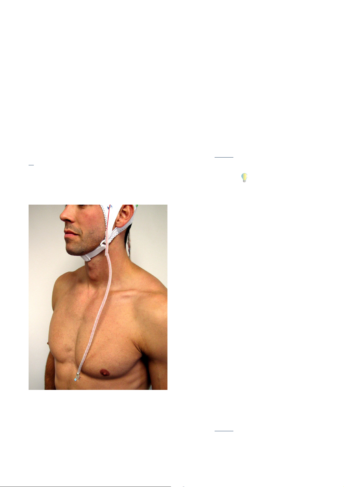
In older versions of the BrainCap MR (Series 2), the ECG electrode leaves the cap in the vicinity
of the left temple and is intended to be positioned on the left side of the thorax (see Figure 2-
10). The use of adhesive rings facilitates the securing of the electrode.
If you attach the ECG electrode as far down as possible, using the entire length of the cable,
maximum amplitude of the R peaks is achieved and the electrode leads cannot form loops.
Figure 2-9. Attaching the ECG electrode to the thorax
On newer versions of the BrainCap MR (Series 3), the ECG electrode leaves the cap at the occipital pole. You can only attach the ECG electrode to the back of the test subject. You will
achieve the best possible ECG signal quality if you attach the ECG electrode as far down as permitted by the cables, on the back of the test subject along the paravertebral line (see Figure 2-

44 Chapter 2 Preparing and operating the amplifier system in an MR environment
10). Positioning the ECG electrode medially in this manner reduces the amplitude of the scan-
ner artifacts, increases the amplitude of the R peaks and prevents the electrode leads from
forming any loops.
Ensure that the electrode leads are not pulled by any movements that may be made by the
test subject, as this can cause the electrodes to be moved or dislodged. Make sure that the
length of the electrode leads permits some room for such movements.
Figure 2-10. Attaching the ECG electrode to the back
Note that combined ECG-fMRI measurements are always degraded by the magnetorheological
effects and that respiratory movements (or movement of the chest) on the part of the test subject cause artifacts. Although attaching the ECG electrode to the test subject's back ensures
that the quality of the ECG recording is degraded even less due to respiratory movements, both
options for attaching the ECG electrode deliver high quality ECG data that allows you to auto-

Correct use of the connections to the amplifier from the test subject: BrainCap MR, electrode input boxes and MR electrodes 45
matically detect the R peaks and correct the cardioballistic artifacts in the BrainVision Analyzer.
Before starting the measurement, use the Recorder software to check the quality of the ECG
signal. You may need to readjust the ECG electrode in order to optimize the results of any subsequent correction of the cardioballistic artifacts.
2.3.4 GSR-MR recordings (GSR-fMRI)
The GSR-MR module (see Figure 2-11 ff), the BrainAmp ExG MR and the ExG AUX Box allow you
to perform combined GSR-fMRI measurements.
You will find detailed information on using the GSR-MR module in the relevant Operating Instructions. The recommendations in these instructions with respect to the positioning of the
equipment correspond to the regulations for combined EMG-fMRI measurements on the test
subject's limbs (see Section 2.3.2 as of page 40) and the regulations for combined ECG-fMRI
measurements (see Section 2.3.3 as of page 42).
Figure 2-11. GSR-MR module (top view)
Figure 2-12. GSR-MR module with connection to ExG AUX Box (side view)

46 Chapter 2 Preparing and operating the amplifier system in an MR environment
Figure 2-13. GSR-MR module with connections for the GSR-MR electrodes (side view)

Considerations on data quality for combined EEG-fMRI measurements 47
2.4 Considerations on data quality for combined EEG-fMRI measurements
MR imaging and EEG recording have a reciprocal impact on data quality as follows:
The quality of the fMRI data can be degraded by simultaneous recording of an EEG.
The quality of the raw EEG data is degraded by the MR environment.
Artifacts in the MR data caused by the amplifier and the electrode cap are not significant. They
do not present a problem due to the construction of the amplifier and the accessories, which
have been optimized for use in MR scanners, and because of the materials used. This has been
certified accordingly by Siemens and Philips, two of the leading manufacturers of MR scanners.
This is not the case with EEG data, in which the MR scanner causes artifacts which must subsequently be corrected. The scanner artifacts result from the changes to the strength and direction of the magnetic field. The quality of online or offline artifact correction (using the
Artifact Average Subtraction/AAS method) and the quality of the EEG data as such depend on
a number of factors. These include:
Synchronization of the scanner and amplifier systems by means of the SyncBox (see
Section 1.1 as of page 17)
You will find additional information on how to achieve the
best possible data quality
with combined EMG- and
ECG-fMRI measurements in
Section 2.3 as of page 39
For information on correcting
scanner artifacts in the BrainVision Analyzer, refer to the
Analyzer User Manual.
.
Recording of volume triggers (volume markers) provided by the scanner (see Section 1.2 as
of page 23)
Correct amplifier settings in the Recorder workspace
Low impedances of the electrodes
Taut, straight routing of the ribbon cables. If you are using more than one amplifier, secure
the incoming ribbon cables flush with each other using tape.
Avoidance of vibrations
Selection of suitable test subjects who are made familiar with the experimental setup and
the recording environment
Comfortable positioning of the test subject with a minimum of movement
Position of the scanner table. Varying the position of the scanner table can have a positive
influence on the strength of the scanner artifacts.
You must configure the Recorder workspace appropriately in order to achieve the best possible
subsequent correction of the scanner artifacts (see Figure 2-14).

48 Chapter 2 Preparing and operating the amplifier system in an MR environment
Figure 2-14. Configuration of the Recorder workspace
To do this, make the following settings:
Sampling Rate [Hz] = 5000
High Cutoff [Hz] = 250
Resolution [μV] = 0.5
For safety reasons, all the electrodes possess series resistors which must be taken into ac-
count during impedance measurement. To do this, enter the corresponding values in the
channel table under Series Resist. [KOhms]. You can find these values in the data sheet
enclosed with the electrode cap.
Deactivate the notch filter.
Do not use any software filters (e.g. the Raw data saving filter).
Choose AC mode (in DC mode, you must enter appropriate parameters for DC offset correction).

Considerations on data quality for combined EEG-fMRI measurements 49
In addition, you should also take account of the following in order to achieve the best possible
data quality:
The impedances of all electrodes, including the reference electrode and the ground elec-
trode, must be low (< 20 kOhm), and it is essential that all EEG electrodes provide the ex-
pected physiological signals before you start the scan.
All cables must be as short as possible and be routed in a straight line along the Z axis
(head-foot axis) of the scanner.
The helium pump and the air conditioning in the scanner bore often cause electrical noise.
If this happens, consider, possibly after discussing the matter with the scanner manufacturer, whether to switch off the helium pump during combined EEG-fMRI measurements.
Contact your scanner manufacturer for further information. You should also switch off the
air-conditioning if this does not impact on the comfort of the test subject and is not otherwise prohibited.
Operation of the scanner causes vibrations that are transmitted to the amplifier and to the
connection cables in particular. In order to avoid this, stabilize the components with a
sandbag or using another suitable method.
Other causes of vibrations that result in long-term degradation of the data quality can lie
outside the scanner room. Neighboring scanners, refrigeration units in the vicinity or footsteps can transmit vibrations if floors or foundations (ceilings) are unsuitable.
The positioning of the test subject, and in particular the positioning of the test subject's
head, is an extremely important factor in the success of a combined EEG-fMRI measurement. On the one hand, the test subject must be lying as comfortably as possible so that
her musculature is relaxed during the entire recording process. On the other hand, voluntary and involuntary movements (of the head) must be avoided, because they cause artifacts in the EEG data. You should therefore use sandbags, foam cushions and towels to
make the test subject as comfortable as possible, to ensure a stable position and, most
importantly, stabilize her head. Brain Products can supply special ranges of cushions
(memory foam) to help you in this task.
For further information on
care of the test subject, refer
to Section 2.5 as of page 50
.

50 Chapter 2 Preparing and operating the amplifier system in an MR environment
2.5 Care and comfort of the test subject during combined EEGfMRI measurements
Successful neurophysiological and peripheral physiological recordings in an MR environment
require comfortable experimental conditions. This means that test subjects must be thoroughly informed of what will happen during the experiment, that they are positioned comfortably
and that they are cared for throughout the entire experiment. In particular, any test subjects
who are not familiar with MR imaging can perceive a combined EEG-fMRI measurement as being disturbing. Test subjects must therefore be given a detailed briefing regarding the experimental procedure beforehand.
Describe the experimental paradigm to the test subjects in detail and explain how you expect
them to behave and cooperate. Before the measurement starts, you should describe and discuss the wide range of various impressions (noises, vibration, confinement, metallic taste in
mouth) in order to create a relaxed atmosphere that is free of fear for the test subjects.
Studies have shown that the duration of an experiment has a considerable influence on the
acceptance of MR experiments for research purposes. This means that the study protocol
should be followed precisely, avoiding any unnecessary delays.
The well-being of test subjects during the experiment depends to a great extent on whether
they have the possibility of communicating with the experimenter using a good intercom. Contact using a bell/alarm ball is also important to give the test subject a feeling of safety during
the experiment. Show the test subject how the alarm ball works and how to operate it before
the scan starts. This ensures that test subjects know that they can call for help at any time
during the scan. Under these circumstances, a combined EEG-fMRI measurement is a well accepted and tolerated procedure.
Always explain to the test subjects that it is theoretically possible for the electrodes and cables
to heat up.
Test subjects with a known (or sometimes unknown) claustrophobic disposition require particular care. Observe them particularly carefully during the final preparations before the scan
in order to avoid the need to break off the experiment during the scan.
If your test subjects are children, they require particular care in order to ensure their cooperation throughout the entire duration of the experiment.
It is especially important to adhere to the following rules in order to provide the greatest possible level of comfort for test subjects:
Comfortable temperatures: Test subjects must not feel excessively cold or perspire. Pro-
vide blankets where necessary.
The scanner table must be long enough to allow the test subject to adopt a comfortable po-
sition. A knee bolster may improve comfort for the test subject.

Care and comfort of the test subject during combined EEG-fMRI measurements 51
Stabilize the test subject's head as far as possible in order to avoid involuntary movements
of the head (nodding, rolling). Take particular care to ensure that the test subject is positioned comfortably in order to relax the neck musculature. Cushions (memory foam), vacuum pillows, sandbags and the stabilizers of the head coil can all be of assistance here.
Particular care is required when recording sleep EEGs in the scanner in order to prevent involuntary changes of position.
Attach electrodes to the back or the occipital area with particular care. Because the body/
head of the test subject is supported at these points, they can cause considerable pain if
they are not padded sufficiently. For this reason, the BrainCap MR has additional, empty
electrode holders to spread the weight of the head more evenly. You should attach ECG
electrodes to concave sites on the back and also pad them.
Reduce the sound level as far as possible using earplugs, ear protectors or headsets.
If a test subject reports feeling discomfort or pain, have the subject medically examined immediately and, if necessary, ensure that the subject receives appropriate care. Please inform
Brain Products immediately to clarify the exact circumstances of the event (discomfort, pain,
lesions). You will find the contact details for our technical support team on page 9.

52 Chapter 2 Preparing and operating the amplifier system in an MR environment
2.6 Emergency measures
The user documentation provided by the manufacturer of the scanner and local safety regulations also apply without restrictions for combined EEG-fMRI measurements. The scanner operator must be familiar with:
How to switch off the scanner in an emergency
How to release the scanner table in an emergency
How to shut down the amplifier in emergencies
2.6.1 Emergency measures to release the test subject
If it is necessary to abort the scan in an emergency, you must disconnect any cables connected
to the amplifier before moving the scanner table.
If you have placed the amplifier inside or outside the scanner bore rather than on the scanner
table, it is not able to follow any movement of the scanner table. You must therefore disconnect the electrode cap from the amplifier before moving the scanner table. The plugs of all cables that connect the amplifier to the electrode cap are therefore fitted with clamps at both
ends (see Figure 2-15). To remove the plug from the socket, press both clamps at the same
time. The plug is released automatically.
Figure 2-15. Clamps on the connection cables of the amplifier and cap
If your scanner table extends beyond the head and you have positioned the amplifier on the
table, it is not necessary to disconnect the electrode cap from the amplifier before moving the
scanner table, because the amplifier automatically follows any movement of the table. However, in this case, the fiber optic cables must always be long enough to allow the amplifier to
move freely.

When the scanner table is stationary outside the scanner bore, remove the head coil carefully
in order to avoid pulling the cables of the electrode cap.
It is normally not necessary to remove the electrode cap from the test subject as a matter of
priority. If necessary, remove any sensors and electrodes that have been additionally attached.
2.6.2 Measures in the event of an amplifier system malfunction or fault
Before starting the measurement, explain to the test subject what to do if she suspects or becomes aware of a problem with the amplifier, the electrode cap or the other EEG accessories.
Show the test subject how the alarm ball works and how to operate it.
Emergency measures 53
If it is necessary to abort the measurement due to a malfunction or fault in the EEG components, proceed as follows:
1 Switch the amplifier off.
2 Disconnect the test subject from the amplifier and electrode cap as well as from any sen-
sors that may be present (see also Section 2.6.1 on page 52
3 Help the test subject leave the scanner bore.
4 Contact our technical support team for detailed advice.
5 Check that the amplifier system is working properly and that all the system components are
installed correctly.
6 If it is not possible to eliminate the malfunction or if the problem persists, send a detailed
description of what has occurred to our technical support team. On request, we will send
you a form that will help clarify the exact reasons for the problem.
).

54 Chapter 2 Preparing and operating the amplifier system in an MR environment

Appendix A Product identification
Product designation: BrainAmp MR,
BrainAmp MR plus,
BrainAmp ExG MR
Manufacturer: Brain Products GmbH
Zeppelinstraße 7
82205 Gilching
Germany
Phone: +49 8105 73384 - 0
Fax: +49 8105 73384 - 505
Web site: http://www.brainproducts.com
Email: techsup@brainproducts.com
55
CE marking The Brain Products GmbH confirms the electromagnetic compatibility (EMC) of
this product according to the Directive 2014/30/EU of the European Parliament
and of the Council of 26 February 2014 on the harmonisation of the laws of the
Member States relating to electromagnetic compatibility.
Electrical safety according to IEC 60601: Protection class II
Warranty The terms of warranty can be found on our web site at: www.brainproducts.com/
contact.php
BrainAmp MR Operating and Reference Manual for use in MR environment | Version 019 | September 29, 2016

56 Appendix A Product identification

Appendix B Explanation of the markings on the products
Observe the manual.
These symbols indicate that defective products must not be disposed of with
household waste. Dispose of in accordance with national regulations or return
the products and its accessories to the manufacturer.
This mark confirms compliance with the environmental requirements for electronic products (only applies to China).
MR Unsafe: Products with this mark are not safe for use in an MR environment.
57
MR Conditional: Products with this mark are only suitable for use in an MR environment subject to certain conditions. Take note of the special application stipulations.
MR Safe: Products with this mark can be used safely in an MR environment.
The Brain Products GmbH confirms the electromagnetic compatibility (EMC) of
this product according to the Directive 2014/30/EU of the European Parliament
and of the Council of 26 February 2014 on the harmonisation of the laws of the
Member States relating to electromagnetic compatibility.
BrainAmp MR Operating and Reference Manual for use in MR environment | Version 019 | September 29, 2016

58 Appendix B Explanation of the markings on the products

Appendix C Phantom measurements in MR environments
If you wish to perform phantom measurements in the scanner with the BrainCap MR and BrainAmp MR amplifier, special care must be taken if you are to obtain reliable imaging results and
avoid damage to the amplifier.
Phantoms provided by the scanner manufacturer usually have a non-conductive surface. When
you attach the electrode cap to the phantom and connect it to the amplifier, all the electrodes
show high impedances.
The amplifier can be destroyed by antenna effects if pulse sequences are run.
Proceed as follows to avoid destroying the amplifier:
Before you attach the BrainCap MR, ensure that the entire surface of the phantom is coated
with a conductive layer of Abralyte gel.
59
After you have attached the BrainCap MR to the fully gel-coated phantom, ensure that the
cap fits as tightly as possible to the surface by tightening the chin strap. Attach the EOG
and ECG electrodes under the edge of the cap.
Make sure that all the electrodes show impedances as low as with a normal measurement
(< 20 kOhm). Use impedance mode to check the electrode impedances while you reduce
the impedances using a syringe and a further quantity of Abralyte gel. All the stipulations
given in Chapter 2 with respect to setting up and positioning the components also apply.
Once you have prepared all the electrodes in this way, take the phantom into the scanner
room and position it and the amplifier in the same way as with a normal measurement.
We recommend that you check the impedances again before starting the scan.
BrainAmp MR Operating and Reference Manual for use in MR environment | Version 019 | September 29, 2016

60 Appendix C Phantom measurements in MR environments

Appendix D Using temperature measurements to verify that the
study is set up safely
The main risk that arises when performing combined EEG-fMRI measurements is the rise in
temperature of EEG components and cables, which can, in the worst case, lead to burns to the
skin or tissue of the test subject.
In order to preclude any risk during the course of a study, we strongly recommend that you
verify the safety margins provided by the final setup of your study. The person running the
study is responsible for carrying out this verification. This applies in particular if you are using
a body coil as an RF transmitter coil, and also if the MR sequences that are to be used are within
the SAR limits laid down in the relevant legislation. This is because:
SAR limits laid down in the relevant legislation do not take account of the presence of ad-
ditional conductive components.
61
The SAR also depends on the composition of the tissue (lean tissue mass/adipose tissue
mass) and the weight of the test subject.
SAR calculations vary from manufacturer to manufacturer and even between identical sys-
tems from the same manufacturer.
Pilot temperature tests are possible both in vitro (special MR phantoms) and in vivo (test subject). Only in vivo tests, however, are likely to have the potential to realistically reflect the safety margins.
Temperature measurements run the risk of returning false low results if they are not performed
correctly. The list below provides an overview of the criteria for validating the setup of a study:
You require a statistically significant number of test subjects covering the weight range of
the planned study.
Use the same MR sequences, scanner configuration and EEG configuration as you will use
in the planned study.
Use temperature measuring equipment that is suitable for use in an MR environment and
that has the following characteristics: Calibrated, adequate resolution, sufficiently small
probes (Ga/As, fluoroptic probes) to allow measurements in the layer of gel between the
skin and the electrodes, a sufficient number of probes to allow a statistically significant
number of electrodes to be measured. The temperature measurement system must also
have an adequate sampling rate and sufficient storage capacity to permit offline analysis.
Equilibrium temperatures must be calculated offline by fitting the data obtained to the un-
derlying exponential function.
Any equilibrium temperatures above 40 °C are critical. A single incidence of a critical rise
in temperature means that the setup for the study must be classified as unsafe, irrespective of the number of test subjects with whom any rise in temperature remained below the
critical level.
BrainAmp MR Operating and Reference Manual for use in MR environment | Version 019 | September 29, 2016

62 Appendix D Using temperature measurements to verify that the study is set up safely
Figure D-1 shows the results of a temperature measurement at one electrode in an EEG cap
during various imaging sequences in a trial with a test subject (Siemens TIM Trio, 12-channel
head receiver coil, body coil as transmitter coil). The measurement data was extrapolated up
to equilibrium temperature. Marked rises in temperature are clearly visible for the Spin Echo,
Turbo Spin Echo and FLAIR sequences.
Figure D-1. Results of temperature measurement, Siemens TIM Trio with 12-channel head
receiver coil and body transmitter coil

Appendix E Guidelines on the safe conduct of combined EEG-fMRI
measurements
These guidelines summarize the most important safety-related instructions that must be observed during combined EEG-fMRI measurements and are intended to help you conduct your
measurements. Great care was taken during the production of these guidelines. However, we
cannot accept any responsibility in respect of the completeness of the information presented
here.
The individual factors and parameters that play a role during combined EEG-fMRI measurements are indicated in color. These include, for example, the structural features of the scanner,
the transmission capabilities of the head coil, the MR sequences used, the EEG accessories
and the area of application for which you intend to perform the measurement.
The colors have the following meanings:
63
Green: Guarantees safe use.
Yellow: Safe use is guaranteed only under certain conditions which must be strictly ad-
hered to.
Red: Safe use is not guaranteed. There is a risk of a health hazard for the test subject, the
user or third-parties and/or of damage to the amplifier. We expressly recommend that you
do not use the corresponding component in your experimental setup.
1 Head coil geometry
a Open head coil
Example: Rapid Biomedical 8-channel
An open head coil makes it possible to route the connecting cables between the EEG cap
and the amplifier in a straight line (see Figure E-1
section "Cable routing" on page 71 ff).
Figure E-1. Open head coil
), thus preventing any loops (see also the
BrainAmp MR Operating and Reference Manual for use in MR environment | Version 019 | September 29, 2016

64 Appendix E Guidelines on the safe conduct of combined EEG-fMRI measurements
b Special head coil adapted for EEG recordings with an opening at the back
Example: Philips 32-channel
This head coil makes it possible to route the connecting cables between the EEG cap and
the amplifier in a straight line (see Figure E-2
tion "Cable routing" on page 71 ff).
Figure E-2. Head coil adapted for EEG recordings
), thus preventing any loops (see also the sec-
c Head coil with side opening
Example: Siemens 12-channel
This head coil makes it possible to route the connecting cables between the EEG cap and
the amplifier through the side of the coil (see Figure E-3
). The cables exit through the side
of the coil and then bend before continuing to the amplifier. Loops are prevented. Please
note that models with a side opening are not as well suited to combined measurements as
open head coils or head coils that have been specially adapted for EEG recordings. However, they offer an adequate level of safety provided that the connecting cables can be led
out of the head coil without any loops forming (see also the section "Cable routing" on
page 71 ff).

Figure E-3. Head coil with side opening
Guidelines on the safe conduct of combined EEG-fMRI measurements 65

66 Appendix E Guidelines on the safe conduct of combined EEG-fMRI measurements
d Closed head coil
Example: Siemens 32-channel
When a closed head coil is used, it is not possible to run the cables in a straight line (see
Figure E-4
). A loop will unavoidably be formed because the bundled connecting cable must
be led back along the electrode cap inside the coil (see also the section "Cable routing" on
page 71 ff).
Figure E-4. Closed head coil
2 Further head coil characteristics
a Head coil as combined transmitter-receiver coil
Example: Siemens 8-channel CP Tx/Rx
Combined transmitter-receiver coils provide the highest possible level of safety for combined EEG-fMRI measurements.
b Head coil as receiver coil only
Head coils without transmission capabilities (body coil is used as the transmitter coil) are
only of limited suitability for combined EEG-fMRI measurements. The following conditions
must be satisfied in order to ensure safe use:
No sensors must be used in the gradient field (for example, EMG, acceleration sensor/
3D Acceleration Module).
Only an EEG cap may be used.
The EEG cap must possess electrodes that are permanently fastened in the material.

Guidelines on the safe conduct of combined EEG-fMRI measurements 67
The EEG cap must possess no more than two drop-down electrodes (typically an ECG
and EOG electrode).
c Multi-transmit coils: Only following individual training
d Parallel transmit coils: Only following individual training
3 Stabilization of the test subject
Stabilize the test subject's head in the head coil to prevent even accidental movements.
Figure E-5. Stabilization of the test subject in the head coil
4 Sequences
a Patient Orientation Sequence
i Localizer, Scout
b Functional (fMRI)
i BOLD imaging/Gradient Echo EPI (GRE, FFE, GE, FE)
ii BOLD imaging/Spin Echo (SE)
iii CBF (ASL, CBV)
iv Diffusion Tensor Imaging
v Spectroscopy
c Anatomical (MRI)

68 Appendix E Guidelines on the safe conduct of combined EEG-fMRI measurements
i MP-RAGE
ii FLASH
iii Other
5 Static gradient field
a Siemens: <= 3 Tesla
b Philips: <= 3 Tesla
c General Electric: <= 3 Tesla
Note: Initial installation and safety training provided by local dealer.
>= 7 Tesla: Only with individual training provided by Brain Products Technical Support.
6 Scanner types/manufacturers
a 60 cm (example: Philips Achieva, Siemens Magnetom Trio)
b 70 cm (example: Siemens Skyra, Siemens Verio, Philips Ingenia)
7 EEG amplifiers and accessories
a Positioning of the amplifier
i EEG amplifier
The EEG amplifier should usually be positioned at the head end of the scanner either
outside or inside the bore (see Figure E-6
and Figure E-7).

Guidelines on the safe conduct of combined EEG-fMRI measurements 69
Figure E-6. Positioning of the EEG amplifier at the head end of the scanner outside of the bore
Figure E-7. Positioning of the EEG amplifier at the head end of the scanner inside the bore
ii ExG amplifier
The ExG amplifier should usually be positioned at the foot end of the scanner (see
Figure E-8).

70 Appendix E Guidelines on the safe conduct of combined EEG-fMRI measurements
Figure E-8. Positioning of the ExG amplifier at the foot end of the scanner
iii Parallel use of EEG and ExG amplifiers
If your experimental setup makes use of an EEG and an ExG amplifier in parallel then
you must position the EEG amplifier (for the EEG electrodes or the electrode cap) at the
head end and the ExG amplifier (for other sensors) at the foot end of the scanner (see
Figure E-9
). It is expressly prohibited to locate both amplifiers in the same position
(both amplifiers at the head end or foot end of the scanner).

Figure E-9. Positioning of EEG and ExG amplifiers for parallel use
Guidelines on the safe conduct of combined EEG-fMRI measurements 71
b Cable routing
i Taut, straight cable routing (see Figure E-10
)
Loops, kinks etc. must be avoided under all circumstances (see Figure E-11
Cables without sheathing must under no circumstances come into contact with the
skin.
Figure E-10. Taut, straight cable routing
Figure E-11. No loops or kinks
).

72 Appendix E Guidelines on the safe conduct of combined EEG-fMRI measurements
ii Combined EEG-fMRI measurements
The EEG amplifier should usually be positioned centrally and aligned straight behind
the head coil inside the scanner (see Figure E-12
If it is not possible to position it in the scanner bore due to certain conditions relating
to the experimental setup, such as the use of projection screens for example, then the
amplifier must be positioned centrally and aligned straight behind the head coil outside of the scanner bore. Any uncovered lengths of cable and the amplifier itself must
be weighted down with sandbags permitted for use in fMRI applications in order to protect them against scanner vibrations (see Figure E-13
).
).
Figure E-12. Positioning of the EEG amplifier inside the scanner bore

Figure E-13. Weighting down the EEG amplifier with sandbags
Guidelines on the safe conduct of combined EEG-fMRI measurements 73
iii Combined GSR-fMRI measurements
The amplifier must be positioned at the foot end of the scanner (see Figure E-14). All the
cables must run straight and taut (see Figure E-15 and Figure E-16).

74 Appendix E Guidelines on the safe conduct of combined EEG-fMRI measurements
Figure E-14. Positioning of the EEG amplifier and accessories for GSR-fMRI
Figure E-15. Positioning of the GSR-MR module

Figure E-16. Attachment of the GSR-MR electrodes
Guidelines on the safe conduct of combined EEG-fMRI measurements 75
iv 3D Acceleration Module
If you are using the 3D Acceleration Module (acceleration sensor) then the amplifier
must be positioned at the foot end of the scanner (see Figure E-17
). All the cables must
run straight and taut.

76 Appendix E Guidelines on the safe conduct of combined EEG-fMRI measurements
Figure E-17. Positioning of the amplifier when the 3D Acceleration Module is used
v Combined EMG-fMRI measurements
The amplifier must be positioned at the foot end of the scanner. All the cables must run
straight and taut (see Figure E-18
and Figure E-19).

Figure E-18. Attachment of the EMG electrodes to the arm
Guidelines on the safe conduct of combined EEG-fMRI measurements 77
Figure E-19. Attachment of the EMG electrodes to the leg

78 Appendix E Guidelines on the safe conduct of combined EEG-fMRI measurements
i Combined ECG-fMRI measurements
The ECG electrode integrated in the electrode cap must be attached without loops.
However, small movements of the head should still be possible without the risk of detaching the electrode (see Figure E-20
Figure E-20. Attachment of the ECG electrode
).
ii Combined EOG-fMRI measurements
The EOG electrode integrated in the electrode cap must be attached without loops (see
Figure E-21
).

Figure E-21. Attachment of the EOG electrode
Guidelines on the safe conduct of combined EEG-fMRI measurements 79
8 EEG cap
a Permitted montages/configurations
i BP standard
ii Electrode positions that are fixed inside the cap
iii Up to three dropdown electrodes with a maximum length of 12 cm from the cap fabric
border and one ECG electrode
9 Number of EEG channels
Unlimited
10 Training of new personnel
In addition to the present guidelines, you must also adhere to the Medical Products Operator
Ordinance (German MPBetreibV) or the applicable national legislation relating to operators. Always make sure that new personnel in your organization receive comprehensive training in the
correct use of the equipment.

80 Appendix E Guidelines on the safe conduct of combined EEG-fMRI measurements
11 General rules of conduct
Respect the safety regulations that apply to the scanner room or the MR environment.
Avoid any (major) movement of the test subject or the equipment (see also Section 2.3.2
as of page 40).
12 Particular attention/supervision is required in the case of
Children, newborns
Test subjects in a poor state of health
Uncooperative test subjects
Sleep EEG
Epilepsy
Sedation

Appendix F Elimination of errors and sources of interference
Below you will find a list of the most frequent problems and sources of interference which
should be eliminated before you start your measurement:
1 Helium pump
The scanner's helium pump can cause electrical noise. If this happens, consider, possibly
after discussing the matter with the scanner manufacturer, whether to switch off the helium pump during combined EEG-fMRI measurements.
2 Air conditioning for patient comfort
The air conditioning system installed in the scanner bore to ensure patient comfort can
also cause interference. You should switch off the air-conditioning if this does not impact
on the comfort of the test subject and is not otherwise prohibited.
81
3 Electrical interference
Make sure that any electrical equipment present do not cause interference in the 50-/60-
Hz range.
4 Vibrations
Operation of the scanner causes vibrations that are transmitted to the amplifier and to the
connection cables in particular. In order to avoid this, stabilize the components with a
sandbag or using another suitable method.
5 Footsteps
You should note that unsuitable floors or foundations (ceilings) can lead to vibrations.
6 Time of repetition
You should choose a multiple of 500 ms for the time of repetition value.
7 Clock timing
Use the SyncBox to synchronize the sampling rate of the amplifier with the scanner clock
rate.
8 Volume markers and clock synchronization
Volume markers are markers in the EEG data that indicate the starting point of each MR volume. These markers must be located at a constant interval from one another. You can
check this, for example, by using the Analyzer.
If you are using the SyncBox in your experimental setup then the interval must be absolutely identical. If you are not using the SyncBox then it is permissible for the interval between
two markers to vary by one data point.
If the intervals between the volume markers vary more than expected then there is a synchronization problem. In this event, contact our technical support team.
BrainAmp MR Operating and Reference Manual for use in MR environment | Version 019 | September 29, 2016

82 Appendix F Elimination of errors and sources of interference

Appendix G Recommended reading
Carmichael, D. W., J. S. Thornton, et al. (2010), Feasibility of simultaneous intracranial EEG-fMRI: A safety study, in: Neuroimage 49(1): 379-390.
Debener, S., et al. (2008), Properties of the ballistocardiogram artefact as revealed by EEG recordings at 1.5, 3 and 7 T static magnetic field strength, in: Int J Psychophysiol
Lemieux, L., P. J. Allen, et al. (1997), Recording of EEG during fMRI experiments: patient safety,
in: Magn Reson Med
Laufs, H. (2012), A personalized history of EEG-fMRI integration, in: Neuroimage, doi:10.1016/
j.neuroimage.2012.01.039.
Mandelkow, H., P. Halder, et al. (2006), Synchronization facilitates removal of MRI artefacts
from concurrent EEG recordings and increases usable bandwidth, in: Neuroimage
1126.
38(6): 943-952.
67(3): 189-199.
32(3): 1120-
83
Meriläinen, V. (2002), Magnetic resonance imaging with simultaneous electroencephalography recording: Safety issues. Department of Electrical and Communications Engineering Helsinki, Helsinki University of Technology; Master: 84.
Mullinger, K., S. Debener, et al. (2008), Effects of simultaneous EEG recording on MRI data
quality at 1.5, 3 and 7 tesla, in: Int J Psychophysiol 67(3): 178-188.
Mullinger, K. J., P. S. Morgan, et al. (2008), Improved artifact correction for combined electroencephalography/functional MRI by means of synchronization and use of vectorcardiogram recordings, in: J Magn Reson Imaging
Mullinger, K. and R. Bowtell (2011), Combining EEG and fMRI, in: Methods Mol Biol 711: 303-
326.
Mullinger, K. J., W. X. Yan, et al. (2011), Reducing the gradient artefact in simultaneous EEGfMRI by adjusting the subject's axial position, in: Neuroimage 54(3): 1942-1950.
Nitz, W. R., G. Brinker, et al. (2005). Specific absorption rate as a poor indicator of magnetic
resonance-related implant heating, in: Invest Radiol
Noth, U., et al. (2012), Simultaneous electroencephalography-functional MRI at 3 T: an analysis
of safety risks imposed by performing anatomical reference scans with the EEG equipment in
place, in: J Magn Reson Imaging
Pictet, J., R. Meuli, et al. (2002), Radiofrequency heating effects around resonant lengths of
wire in MRI, in: Phys Med Biol
27(3): 607-616.
40(12): 773-776.
35(3): 561-571.
47(16): 2973-2985.
Ritter, P., A. Villringer (2006), Simultaneous EEG-fMRI, in: Neurosci Biobehav Rev 30(6): 823-
838.
Ritter, P., et al. (2007), Evaluating gradient artifact correction of EEG data acquired simultaneously with fMRI, in: Magn Reson Imaging 25(6): 923-932.
Rosenkranz, K., L. Lemieux (2010), Present and future of simultaneous EEG-fMRI, in: MAGMA
23(5-6): 309-316.
BrainAmp MR Operating and Reference Manual for use in MR environment | Version 019 | September 29, 2016

84 Appendix G Recommended reading
Warbrick, T., A.P. Bagshaw (2008), Scanning strategies for simultaneous EEG-fMRI evoked potential studies at 3 T, in: Int J Psychophysiol 67(3): 169-177.
Yan, W. X., K. J. Mullinger, et al. (2009), Understanding gradient artefacts in simultaneous EEG/
fMRI, in: Neuroimage
46(2): 459-471.
You can also find a list of publications in which our amplifier system or accessories are referred
to within the EEG-fMRI field on our web site under the link http://www.brainproducts.com/ref-
erences.php.

General list of abbreviations
AAS ...........................Artifact Average Subtraction
AC ............................. Alternating current
DC .............................Direct current
ECG ........................... Electrocardiography
EMG .......................... Electromyography
EOG........................... Electrooculography
85
FDA............................ Food and Drug Administration
fMR............................ Functional magnetic resonance imaging
GSR ...........................Galvanic skin response
ISO ............................ International Organization for Standardization
RF.............................. Radio frequency
SAR ........................... Specific absorption rate
TTL............................. Transistor-transistor logic
BrainAmp MR Operating and Reference Manual for use in MR environment | Version 019 | September 29, 2016

86 General list of abbreviations

List of abbreviations for the cited MR sequences and methods
ASL............................ Arterial Spin Labeling
BOLD......................... Blood Oxygen Level Dependent
CBF............................ Cerebral Blood Flow
CBV ...........................Cerebral Blood Volume
DTI............................. Diffusion Tensor Imaging
EPI............................. Echo Planar Imaging
87
FE .............................. Fast Echo
FFE ............................ Fast Field Echo
FLAIR .........................Fluid Attenuated Inversion Recovery
FLASH........................ Fast Low Angle Shot
FSE ............................ Fast Spin Echo
FSPGR........................ Fast Spoiled Gradient Echo
GE ............................. Gradient Echo
GRE ........................... Gradient Echo
MP-RAGE ................... Magnetization Prepared Rapid Gradient Echo
SE.............................. Spin Echo
SPGR .........................Spoiled Gradient Recalled
TFE ............................ Turbo Field Echo
TSE............................ Turbo Spin Echo
BrainAmp MR Operating and Reference Manual for use in MR environment | Version 019 | September 29, 2016

88 List of abbreviations for the cited MR sequences and methods

Subject index
89
A
amplifier
damage 33–34
safe operating position 35–38
Analyzer 42, 44
artifact correction 17, 23, 47
ECG 44
EMG 42
B
blood pulse artifact 42
correction 44
BrainCap MR 33, 39–40, 42, 51
C
cable routing
incorrect 29
safe 17, 31, 35, 39, 43
clock synchronization 17, 25, 81
Conditions of use 14
conditions of use 8
current-limiting resistor 39, 40, 48
D
functional test, performing 25
G
GSR recordings 45–46
I
impedances
measuring 48
minimizing 33, 34, 49
installation
overall system 8
Recorder 17
SyncBox 18–20
M
magnetic field strengths 27
maintenance 8
marker 23, 81
P
pinout 8
positioning of the EEG components 35–38
PowerPack 34, 37, 41
data quality 47–49
ECG 42–44
EMG 42
driver, for SyncBox 18
E
ECG electrode 33, 40
attaching 43–44
ECG recordings 42–45
EEG cap 37, 39–40
connecting 36
emergencies
activities 51
emergency measures 52–53
EMG recordings 40–42
EMG-FaceCap 42
EOG electrode 34
ExG AUX Box 34, 41
F
fiber optic cables 35, 38
R
Recorder 7, 18
workspace 33, 47–48
RecView 42
ring electrodes, safe fitting of 39–40
S
sampling rate 48
scanner
clock signal output 17, 20
gradient clock board 17
volume trigger output 23, 24
sensors 39
sequences
prohibited 32
safe 32
sleep EEG 37, 51
slice trigger 23
specific absorption rate (SAR) 31, 61
support (contact) 9
BrainAmp MR Operating and Reference Manual for use in MR environment | Version 019 | September 29, 2016

90 Subject index
SyncBox 42
installation 18–20
synchronization marker 25
T
technical data 8
test subject care 49, 50–51, 53
time of repetition 32, 81
U
USB2 Adapter 20, 24
V
vibrations, reducing 38, 49
volume marker 25, 81
volume trigger 23
W
Warranty 55
workspace configuration 47–48
 Loading...