

Page 1

PR Series Process Control Card PC201 User Guide
UMPC201A
October 2016
Page 2

Warning Symbol
The Symbol calls attention to an operating procedure, practice, or the like, which, if not
correctly performed or adhered to, could result in personal injury or damage to or destruction of part
or all of the product and system. Do not proceed beyond a warning symbol until the indicated
conditions are fully understood and met.
Preface
Original equipment manufacturer reserves the right to change information available in this
document without notice. Manufacturer is not liable for any damages incurred to
equipment/personal during installation or use of equipment as explained in this document. User
must acquire sufficient knowledge & skills prior to use the equipment in the application and follow
all the local standards & regulations to meet safety requirements
Copyright
The documentation and the software included with this product are copyrighted 2016 By
Brainchild Electronic Co. Ltd. All rights are reserved. Brainchild Electronic Co., Ltd. reserves the
right to make improvements in the products described in this manual at any time without notice.
No part of this manual may be reproduced/ copied/ translated or transmitted in any form or by any
means without the prior written permission of Brainchild Electronic Co .,Ltd. The information we
supply is believed to be accurate and reliable as of this printing. However, we assume no
responsibility for its use.
Contact Information
Head Office & Factory
Brainchild Electronic Co. Ltd.
209 Chongyang Road, Nangang Dist.,
Taipei 11573,Taiwan
Tel: +886-2-2786-1299 Fax: +886-2-2786-1395
Website: www.brainchild.com.tw
China Sales Office
Brainchild Electronic (Kunshan) Co. Ltd.
Room 405, Building #6, Huamin Gentlefolk Garden
No. 13, Qianjin Central Road, Kunshan City, Jiangsu 215300, China
Tel: +86-512-5511-6133 Fax: +86-512-5511-6113
Website: www.brainchild.com.cn
Page 2 of 113
Page 3

TABLE OF CONTENTS
1
INTRODUCTION ---------------------------------------------------------------------- ------------------------------- 8
1.1 I
NTRODUCTION
1.2 F
1.3 P
1.4 E
1.5 S
1.6 P
1.7 S
EATURES
ROCESS CONTROL CARD
1.3.1 Flexible Configuration of Program ------------------------------------------------------------------ 11
1.3.2 Maximum Capacity of Program --------------------------------------------------------------------- 11
1.3.3 Event Input ----------------------------------------------------------------------------------------------- 11
1.3.4 Programmable Event Outputs ----------------------------------------------------------------------- 11
1.3.5 High Accuracy ------------------------------------------------------------------------------------------- 11
1.3.6 Fast Sampling Rate ------------------------------------------------------------------------------------- 11
1.3.7 Fuzzy Control -------------------------------------------------------------------------------------------- 12
1.3.8 Auto-tuning ---------------------------------------------------------------------------------------------- 12
1.3.9 Lockout Protection ------------------------------------------------------------------------------------- 12
1.3.10 Bumpless Transfer -------------------------------------------------------------------------------------- 12
1.3.11 Digital Filter --------------------------------------------------------------------------------------------- 12
1.3.12 Soft-start Ramp ----------------------------------------------------------------------------------------- 12
1.3.13 Pump Control -------------------------------------------------------------------------------------------- 12
XPANSION
1.4.1 PID Control Module ------------------------------------------------------------------------------------ 12
MART MECHANISM
ROCESS CONTROL CARD
PECIFICATION
1.7.1 Input1 ----------------------------------------------------------------------------------------------------- 14
1.7.2 Input2 ----------------------------------------------------------------------------------------------------- 15
1.7.3 Input3 (Event Input) ------------------------------------------------------------------------------------ 16
1.7.4 Output1/Output2 --------------------------------------------------------------------------------------- 16
1.7.5 Alarm 1/ Alarm 2 --------------------------------------------------------------------------------------- 17
1.7.6 Control Mode -------------------------------------------------------------------------------------------- 17
1.7.7 Digital Filter --------------------------------------------------------------------------------------------- 18
----------------------------------------------------------------------------------------------------- 8
----------------------------------------------------------------------------------------------------------- 8
------------------------------------------------------------------------------------------ 9
I/O M
ODULES FOR
--------------------------------------------------------------------------------------------- 13
---------------------------------------------------------------------------------------------------- 14
PID ----------------------------------------------------------------------------- 12
PC201 O
RDERING CODE
------------------------------------------------------------- 13
2
INSTALLATION AND WIRING----------------------------------------------------------------------------------- 19
2.1 U
2.2 I
3
3.1 C
3.2 C
3.3 R
3.4 ON F
4
4.1 M
4.2 S
NPACKING
NPUT OUTPUT WIRING CONNECTION
2.2.1 Wiring Precautions ------------------------------------------------------------------------------------- 20
2.2.2 PID Control Module ------------------------------------------------------------------------------------ 20
PROCESS CONTROL CARD FEATURES ----------------------------------------------------------------------- 22
ONFIGURATION
ONTROLLER
AMP & DWELL FUNCTION
PROCESS CONTROL CARD FUNCTIONS ---------------------------------------------------------------------- 23
ENUS
TATUS BAR
------------------------------------------------------------------------------------------------------- 19
--------------------------------------------------------------------------- 20
-------------------------------------------------------------------------------------------------- 22
------------------------------------------------------------------------------------------------------ 22
-------------------------------------------------------------------------------------- 22
IELD CALIBRATION
------------------------------------------------------------------------------------------------------------ 23
------------------------------------------------------------------------------------------------------- 32
------------------------------------------------------------------------------------------- 22
Page 3 of 113
Page 4

4.3 P
4.4 D
ROCESS CONTROL CARD CONFIGURATION
4.3.1 Process Control Card Configuration ---------------------------------------------------------------- 34
4.3.1.1 Controller --------------------------------------------------------------------------------------------------------- 35
4.3.1.1.1 Name ---------------------------------------------------------------------------------------------------------- 36
4.3.1.1.2 Parameter ---------------------------------------------------------------------------------------------------- 36
4.3.1.1.3 Channel ------------------------------------------------------------------------------------------------------- 72
4.3.1.1.4 Sample Configuration of Process Control Card ------------------------------------------------------ 76
4.3.1.1.4.1 Heat Only ON-OFF Control ------------------------------------------------------------------------- 76
4.3.1.1.4.2 Cool Only ON-OFF Control -------------------------------------------------------------------------- 78
4.3.1.1.4.3 Heat Cool Control ------------------------------------------------------------------------------------ 78
4.3.1.1.4.4 Heater Break Alarm ---------------------------------------------------------------------------------- 80
4.3.1.1.4.5 Loop Break Alarm ------------------------------------------------------------------------------------ 81
4.3.1.1.4.6 Sensor Break Alarm ---------------------------------------------------------------------------------- 81
4.3.1.1.4.7 Failure Transfer --------------------------------------------------------------------------------------- 82
4.3.1.1.4.8 Bumpless Transfer ----------------------------------------------------------------------------------- 83
4.3.1.1.4.9 PV1 Shift ------------------------------------------------------------------------------------------------ 84
4.3.1.1.4.10 SP1 Range --------------------------------------------------------------------------------------------- 85
4.3.1.1.4.11 Dwell Timer ------------------------------------------------------------------------------------------ 85
4.3.1.1.4.12 Process Alarms -------------------------------------------------------------------------------------- 86
4.3.1.1.4.13 Deviation Alarm ------------------------------------------------------------------------------------- 88
4.3.1.1.4.14 Deviation Band Alarm ------------------------------------------------------------------------------ 90
4.3.1.1.4.15 Event Input ------------------------------------------------------------------------------------------- 91
4.3.1.1.4.16 Second Set Point ------------------------------------------------------------------------------------ 93
4.3.1.1.4.17 Second PID Set --------------------------------------------------------------------------------------- 93
4.3.1.1.4.18 Ramp & Dwell ---------------------------------------------------------------------------------------- 94
4.3.1.1.4.19 Remote Set Point ----------------------------------------------------------------------------------- 96
4.3.1.1.4.20 Differential Control --------------------------------------------------------------------------------- 97
4.3.1.1.4.21 Output Power Limit--------------------------------------------------------------------------------- 98
4.3.1.1.4.22 Digital Filter ------------------------------------------------------------------------------------------ 98
4.3.1.1.4.23 Auto-Tuning and Manual Tuning ---------------------------------------------------------------- 99
4.3.1.2 Ramp & Dwell(Profile) ----------------------------------------------------------------------------------------- 102
4.3.1.2.1 Ramp & Dwell: --------------------------------------------------------------------------------------------- 103
4.3.1.2.2 Segments: --------------------------------------------------------------------------------------------------- 104
4.3.1.2.2.1 Ramp Segment Parameters: ---------------------------------------------------------------------- 105
4.3.1.2.2.2 Dwell Segment Parameters: ---------------------------------------------------------------------- 108
4.3.1.2.2.3 Go Back Segment Parameters: ------------------------------------------------------------------- 108
4.3.1.2.2.4 End Segment Parameters: ------------------------------------------------------------------------- 108
4.3.1.2.2.5 Time to Target Segment Parameters: ----------------------------------------------------------- 109
4.3.1.2.3 Start/End Jobs ---------------------------------------------------------------------------------------------- 109
4.3.1.2.4 Start/Stop Profile(Ramp &Dwell) ---------------------------------------------------------------------- 109
ISPLAY
---------------------------------------------------------------------------------------------------------- 111
--------------------------------------------------------------------- 33
5
APPLICATION ----------------------------------------------------------------------------------------------------- 112
5.1 O
VEN CONTROL WITH ZONE TEMPERATURE RECORDING
------------------------------------------------------ 112
Page 4 of 113
Page 5

Table of Figures
Figure 1-1.Fuzzy PID System Block Diagram ...................................................................................................... 9
Figure 1-2.PID System Stability with and without Fuzzy ................................................................................... 10
Figure 2-1.Process Control Card Wiring Diagram ............................................................................................. 21
Figure 3-1.Configuration Layout ..................................................................................................................... 22
Figure 4-1.Home Screen .................................................................................... ............................................. 23
Figure 4-2.Menu Screen ................................................................................................................................. 24
Figure 4-3.Real Time Menu ............................................................................................................................ 24
Figure 4-4.Overview Display .......................................................................................................................... 25
Figure 4-5.PID Controller Module Display ....................................................................................................... 25
Figure 4-6.Display Modes .............................................................................................................................. 26
Figure 4-7.Real Time Alarms .......................................................................................................................... 26
Figure 4-8.Historical Data Screen ................................................................................................................... 27
Figure 4-9.Event History ................................................................................................................................ 28
Figure 4-10.Report Screen ............................................................................................................................. 29
Figure 4-11.More Menu ................................................................................................................................. 29
Figure 4-12.Operate Menu ............................................................................................................................. 30
Figure 4-13.Configuration Layout ................................................................................................................... 31
Figure 4-14.More Menu ................................................................................................................................. 32
Figure 4-15.Status Bar During Logging ............................................................................................................ 32
Figure 4-16.Status Bar During Logging Stopped ............................................................................................... 32
Figure 4-17.Status Bar during Logging with Batch function ............................................................................. 32
Figure 4-18.Status Bar During Logging Stopped with Batch Function ................................................................ 32
Figure 4-19.Tree Type Configuration Layout ................................................................................................... 33
Figure 4-20.Process Control Card Channel Configuration ................................................................................. 35
Figure 4-21.Process Control Card Channel Configuration ................................................................................. 36
Figure 4-22.Process Control Card Configuration Window ................................................................................. 37
Figure 4-23.Process Control Card Configuration Window for Read only Parameter ........................................... 37
Figure 4-24.Process Control Card Channel Configuration ................................................................................. 72
Figure 4-25.Log Speed ................................................................................................................................... 74
Figure 4-26.Events with Job ........................................................................................................................... 74
Figure 4-27. Event Configuration Example ...................................................................................................... 76
Figure 4-28.Heat Only ON-OFF Control ........................................................................................................... 77
Figure 4-29.Cool Only ON-OFF Control ............................................................................................................ 78
Figure 4-30. Heater Break Alarm .................................................................................................................... 80
Figure 4-31.Without Bumpless Transfer .......................................................................................................... 83
Figure 4-32.With Bumpless Transfer ............................................................................................................... 84
Figure 4-33.PV1 SHIFT Application.................................................................................................................. 85
Figure 4-34.SP1 Range ................................................................................................................................... 85
Figure 4-35.Dwell Timer ................................................................................................................................. 86
Figure 4-36.Normal Process Alarm ................................................................................................................. 87
Figure 4-37.Latching Process Alarm ................................................................................................................ 87
Figure 4-38.Holding Process Alarm ................................................................................................................. 88
Figure 4-39.Latching / Holding Process Alarm ................................................................................................. 88
Figure 4-40.Normal Deviation Alarm .............................................................................................................. 89
Figure 4-41.Latching Deviation Alarm ............................................................................................................. 89
Figure 4-42.Holding Deviation Alarm .............................................................................................................. 89
Figure 4-43.Latching/Holding Deviation Alarm ................................................................................................ 90
Figure 4-44.Normal Deviation Band Alarm ...................................................................................................... 90
Figure 4-45.Latching Deviation Band Alarm .................................................................................................... 91
Figure 4-46.Holding Deviation Band Alarm ..................................................................................................... 91
Page 5 of 113
Page 6

Figure 4-47.Latching/Holding Deviation Band Alarm ....................................................................................... 91
Figure 4-48.Ramp Function ............................................................................................................................ 94
Figure 4-49.Dwell Timer ................................................................................................................................. 95
Figure 4-50.Ramp Accompanied with Dwell Timer .......................................................................................... 96
Figure 4-51.Relationship Between PV1 & PV2 for Differential Control .............................................................. 97
Figure 4-52.Power Limit Function ................................................................................................................... 98
Figure 4-53.Filter Characteristics .................................................................................................................... 99
Figure 4-54.Process Control Module Real time .............................................................................................. 100
Figure 4-55.Auto-Tuning .............................................................................................................................. 100
Figure 4-56.Auto-Tuning In progress ............................................................................................................. 101
Figure 4-57.Manual Tuning In Progress ......................................................................................................... 101
Figure 4-58.Ramp & Dwell Configuration Window ........................................................................................ 102
Figure 4-59.Set Point Profile ........................................................................................................................ 103
Figure 4-60.Ramp Segment .......................................................................................................................... 105
Figure 4-61.Hold Back on Dwell .................................................................................................................... 107
Figure 4-62.Hold Back on Positive Ramp ....................................................................................................... 107
Figure 4-63.Hold Back Negative Ramp .......................................................................................................... 107
Figure 4-64.Dwell Segment ....................................................................................... ................................... 108
Figure 4-65.Go Back Segment....................................................................................................................... 108
Figure 4-66.End Segment ........................................................................................ ..................................... 108
Figure 4-67.Time To Target Segment ............................................................................................................ 109
Figure 4-68.Profile Start/End Job .................................................................................................................. 109
Figure 4-69.Run Profile ................................................................................................................................ 110
Figure 4-70.Profile Running.......................................................................................................................... 110
Figure 5-1.Oven Control with Zone Temperature Recording .......................................................................... 112
Figure 5-2. Oven Control with Zone Temperature Recording System .............................................................. 113
Page 6 of 113
Page 7

Table of Tables
Table 1-1. Input 1 Characteristics ................................................................................................................... 15
Table 1-2. Input 2 Characteristics ................................................................................................................... 16
Table 1-3. Output Characteristics ................................................................................................................... 16
Table 1-4. SSR Output Characteristics ............................................................................................................. 17
Table 2-1.Environmental Specification ........................................................................................................... 19
Table 4-1.PID Parameter List .......................................................................................................................... 47
Table 4-2.Process Control Card Input Range ................................................................................................... 48
Table 4-3.Range of A1SP ................................................................................................................................ 48
Table 4-4.Range of A2SP ................................................................................................................................ 48
Table 4-5.Range Of SP2 .................................................................................................................................. 48
Table 4-6.Mode Selection .............................................................................................................................. 49
Table 4-7.Communication Mode .................................................................................................................... 49
Table 4-8.Communication Protocol ................................................................................................................ 50
Table 4-9.Communication Baud Rate ............................................................................................................. 50
Table 4-10.Communication Data Length ......................................................................................................... 51
Table 4-11.Communication Parity .................................................................................................................. 51
Table 4-12.Communication Stop Bit ............................................................................................................... 51
Table 4-13 Function of AOFN ......................................................................................................................... 52
Table 4-14 Selection of IN1 Type .................................................................................................................... 53
Table 4-15.Display Unit for IN1 & IN2 ............................................................................................................. 53
Table 4-16.Decimal Digit for DP1&DP2 ........................................................................................................... 53
Table 4-17.IN2 Input ...................................................................................................................................... 54
Table 4-18.EIFN Function ............................................................................................................................... 55
Table 4-19.OUT1 Action ................................................................................................................................. 55
Table 4-20.OUT1 & OUT2 Type ....................................................................................................................... 55
Table 4-21.OUT2 Function ............................................................................................................................. 56
Table 4-22.Display Function ........................................................................................................................... 56
Table 4-23. Alarm1 & Alarm 2 Function .......................................................................................................... 57
Table 4-24.Alarm1 & Alarm2 Operation Mode ................................................................................................ 57
Table 4-25.Alarm1 & Alarm2 Failure Transfer Mode ....................................................................................... 58
Table 4-26.Auto Tuning ................................................................................................................................. 58
Table 4-27.Sleep Mode .................................................................................................................................. 58
Table 4-28.PV Mode Selection ....................................................................................................................... 59
Table 4-29.SP2 Set Point Format .................................................................................................................... 59
Table 4-30 Filter Damping Time Constant of PV .............................................................................................. 59
Table 4-31 Set Point Mode Selection .............................................................................................................. 60
Table 4-32 SEL Selection ................................................................................................................................ 61
Table 4-33 Default File Selection .................................................................................................................... 61
Table 4-34.Error Codes and Corrective Actions................................................................................................ 68
Table 4-35 PROG CODE .................................................................................................................................. 69
Table 4-36 Mode ........................................................................................................................................... 70
Table 4-37.Unit Determination for A1SP,A1DV,A1HY ...................................................................................... 70
Table 4-38.Unit Determination for A2SP,A2DV,A2HY ...................................................................................... 71
Table 4-39.RAMP Unit ................................................................................. .................................................. 71
Table 4-40 .Unit Determination of AOLO & AOHI ............................................................................................ 71
Table 4-41.Heat Cool Control Modes .............................................................................................................. 79
Page 7 of 113
Page 8

1 Introduction
1.1 Introduction
Generally most of the furnace applications require Controller and Recorder separately to
control and record the data. Some Furnaces application requires Ramp & Dwell controllers .The
new generation Paperless Recorder provides PID Control, Ramp & Dwell Control and Recording in
one device by using the new process control Card PC201 . This is a single loop controller for
Furnace applications. This will reduce Cost ,Space ,Wiring required for using controller and
Recorder separately.
1.2 Features
The Process Control Card has lot of unique Features on its hardware and Software. The
unique Features are listed below.
PID Controller, Ramp & Dwell Controller and Recorder 3 in one Device
Plug and Play I/O Options
18-bit Universal input A-D for PID Control
15-bit output D-A
Fuzzy + PID microprocessor-based control
Fast input sampling rate 200msec for PID Control
Two level of function complexity
50 Profiles,1000 Segments in Total
Differential control
Auto-tuning and Self Tuning function
Sleep mode function
" Soft-start " Ramp and Dwell timer
Universal inputs( Thermocouple, RTD, mA, VDC )
Analog input for remote set point and CT
Event input for changing function & set point
Programmable digital filter
Hardware lockout + remote lockout protection
Loop break alarm
Heater break alarm
Sensor break alarm + Bumpless transfer
Pump control
Page 8 of 113
Page 9
100msec Sampling rate and log speed for Data Acquisition
Real time and Historical Trends for PV and SV
1.3 Process Control Card
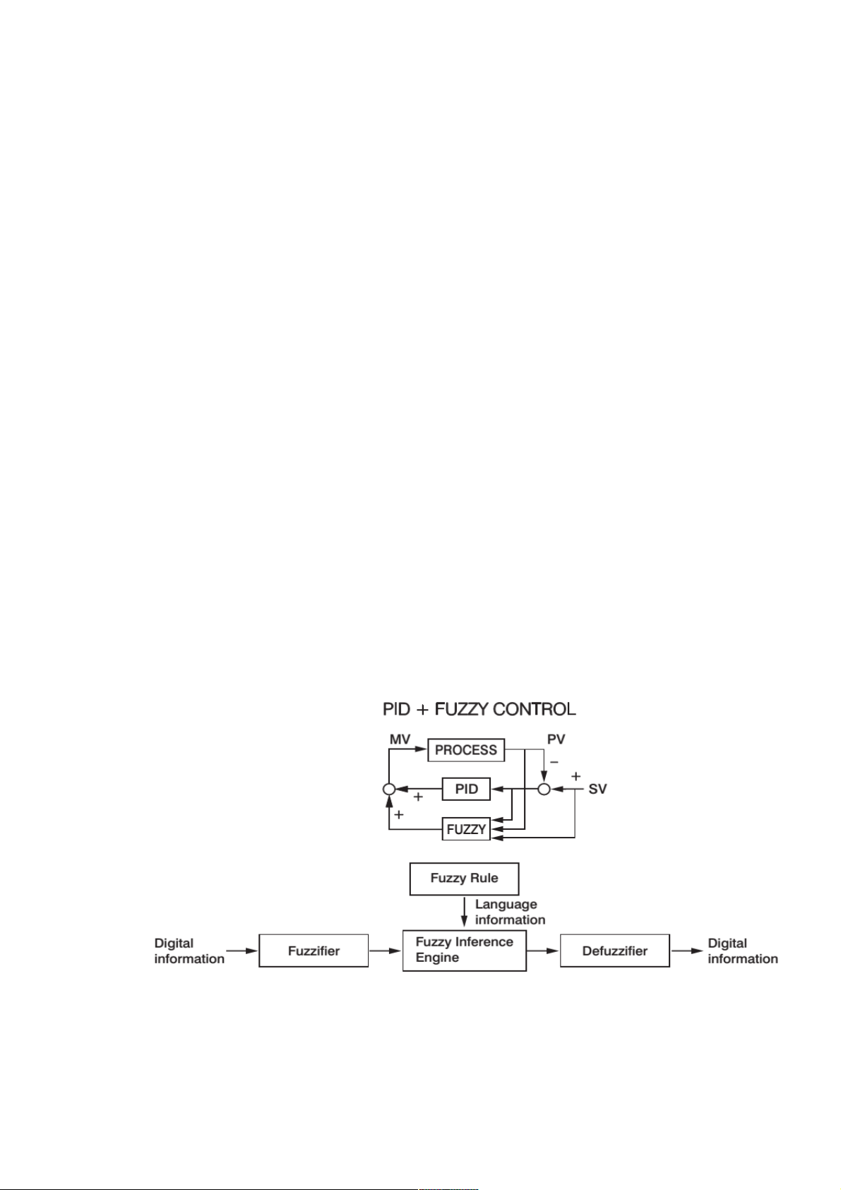
The Process Control Card uses Fuzzy Logic plus PID microprocessor technology for its
control. The Fuzzy Logic plus PID microprocessor based technology enables a process to reach a
predetermined set point in the shortest time, with the minimum of overshoot during power-up or
external load disturbance. The module can be easily plugging into the rear side IO slots of the
paperless recorder. Various control and input parameters can be configured easily by using the
touch screen menus and navigations.
This Process Control Card can be configured by using the Configuration Menu on the
device or by using the PC Based Configuration Software.
Even though PID control has been used and proved to be an efficient controlling method
by many industries for more than a decade, yet the PID is difficult to deal with some sophisticated
systems such as second and higher order systems, long time-lag systems, during set point change
and/or load disturbance circumstance etc. The PID principle is based on a mathematic modeling
which is obtained by tuning the process. Unfortunately many systems are too complex to describe
in numerical terms precisely. In addition to these, systems may be variable from time to time. In
order to overcome the imperfection of PID control, the Fuzzy Technology is introduced.
What is the Fuzzy Control? It works like a good driver. Under different speeds and
circumstances, he can control a car well with experiences he had before and does not require the
knowledge of kinetic theory of motion. The Fuzzy Logic is a linguistic control which is different from
the numerical PID control. It controls the system by experiences and does not need to simulate the
system precisely as been controlled by PID.
Figure 1-1.Fuzzy PID System Block Diagram
Page 9 of 113
Page 10
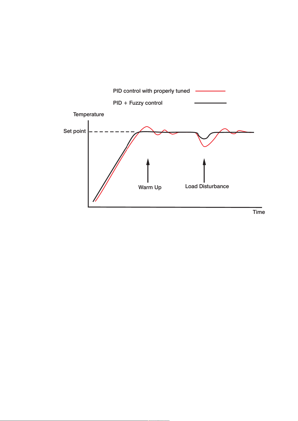
The function of Fuzzy Logic is to adjust PID parameters internally in order to make
manipulation output value MV more flexible and adaptive to various processes.PID + Fuzzy Control
has been proven to be an efficient method to improve the control stability as shown by the
comparison of curves shown below.
Figure 1-2.PID System Stability with and without Fuzzy
The Fuzzy Rule works like the below.
If temperature difference is large and temperature rate is large, then MV is large.
If temperature difference is high and temperature rate is small, then MV is small.
By using proprietary Fuzzy modified PID technology the control loop will minimize the
overshoot and undershoot in a shortest time.
This Process Control Card can be configured as a single set point controller (static mode)
or a ramp and dwell profiling controller (profile mode). The profile mode feature allows the user to
program up to 50 profiles with up to 32 free format Segments (ramp, dwell, jump or end) each. The
total segments available for the product are 1000 segments.
The Process Control Card contains the following features.
Page 10 of 113
Page 11

1.3.1
Flexible Configuration of Program
There are up to 32 segments can be defined for a profile. Each segment can be configured
as a ramp or a dwell (soak) segment or defining a repeat number of cycles at arbitrary location
within the profile and finally terminated by an end segment. The user can edit a currently running
profile.
1.3.2
1.3.3
1.3.4
Maximum Capacity of Program
There are at most 50 Profiles can be defined and 1000 segments totally available for all
profiles. Each Profile can contain maximum of 32 Segments and limited to 1000 Segments in Total.
Event Input
The Event input feature allows the user to select one of eight functions below.
Enter Profile Run Mode
Enter Profile Hold Mode
Abort Profile Mode
Enter Manual Mode
Perform Failure Transfer
Enter Off Mode
Advance to the next segment
Select second set of PID values
Programmable Event Outputs
1.3.5
1.3.6
Up to 3 Relays are configurable for event outputs and the state of each output can be
defined for each segment and end of profile.
High Accuracy
This Process Control Card is manufactured with custom designed ASIC(Application
Specific Integrated Circuit ) technology which contains a 18-bit A to D converter for high resolution
measurement ( true 0.1 F resolution for thermocouple and PT100 ) and a 15-bit D to A converter for
linear current or voltage control output. The ASIC technology provides improved operating
performance with low cost and enhanced reliability and higher density.
Fast Sampling Rate
The sampling rate of the input A to D converter reaches 5 times/second (200msec). The
fast sampling rate allows this Process Control Card to control fast processes.
Page 11 of 113
Page 12

1.3.7
Fuzzy Control
The function of Fuzzy control is to adjust PID parameters from time to time in order to
make manipulation output value more flexible and adaptive to various processes. The results are to
enable a process to reach a predetermined set point in the shortest time with the minimum of
overshoot and undershoot during power-up or external load disturbance.
1.3.8
1.3.9
1.3.10
1.3.11
1.3.12
Auto-tuning
The auto-tuning function allows the user to simplify initial setup for a new system. A
clever algorithm is provided to obtain an optimal set of control parameters for the process, and it can
be applied either as the process is warming up ( cold start ) or as the process has been in steady
state ( warm start ).
Lockout Protection
According to actual security requirement, a password is provided to prevent the unit from
being changed abnormally.
Bumpless Transfer
Bumpless transfer allows the controller to continue to control by using its previous value as
the sensor breaks. Hence, the process can be well controlled temporarily as like the sensor is
normal.
Digital Filter
A first order low pass filter with a programmable time constant is used to improve the
stability of process value. This is particularly useful in certain application where the process value is
too unstable to read.
Soft-start Ramp
The ramping function is performed during power up as well as any time the set point is
changed. It can be ramping up or ramping down. The process value will reach the set point with a
predetermined constant rate.
1.3.13
Pump Control
In addition the fast sampling rate, this Process Control Card has superior noise rejection
capability. So it can be used for pressure control of a Pump which is driven by Variable Frequency
Drives.
1.4 Expansion I/O Modules for PID
The Paperless Recorder have the option to use PID function on it by using the
Process Control Card in to it on the one of the 4 rear slots .
1.4.1
PID Control Module
This module is useful for single loop PID Control. This consists of Two
Signal Inputs, one Event Input and control output and Alarm output as per the specification.
Page 12 of 113
Page 13

1.5 Smart Mechanism
The data is recorded in manufacturer special binary format. It is not possible to manipulate
the data. This feature guarantees the security and reliability of the recorded data .
1.6 Process Control Card PC201 Ordering Code
PC201- □ □ □
□
A B C D
A: Output 1
0: None
1: Relay 2A/240VAC
2: Pulse voltage to drive SSR, 5V/30mA
3: Isolated 4-20mA/0-20mA (OM95-3)
4: Isolated 1-5V/0-5V (OM95-4)
5: Isolated 0-10V (OM95-5)
6: Triac output 1A/240VAC,SSR
C: Pulse voltage to drive SSR, 14V/40mA (OM94-7)
B: Output 2
0: None
1: Relay 2A/240VAC
2: Pulse voltage to drive SSR, 5V/30mA
3: Isolated 4-20mA/0-20mA (OM95-3)
4: Isolated 1-5V/0-5V (OM95-4)
5: Isolated 0-10V (OM95-5)
6: Triac output 1A/240VAC,SSR
7: Isolated 20VDC/25mA power supply (DC94-1)
8: Isolated 12VDC/40mA power supply (DC94-2)
9: Isolated 5VDC/80mA power supply (DC94-3)
C: Pulse voltage to drive SSR, 14V/40mA (OM94-7)
C: Alarm 1
0: None
1: Form C relay 2A/240VAC
D: Alarm 2
0: None
1: Form A relay 2A/240VAC
Page 13 of 113
Page 14
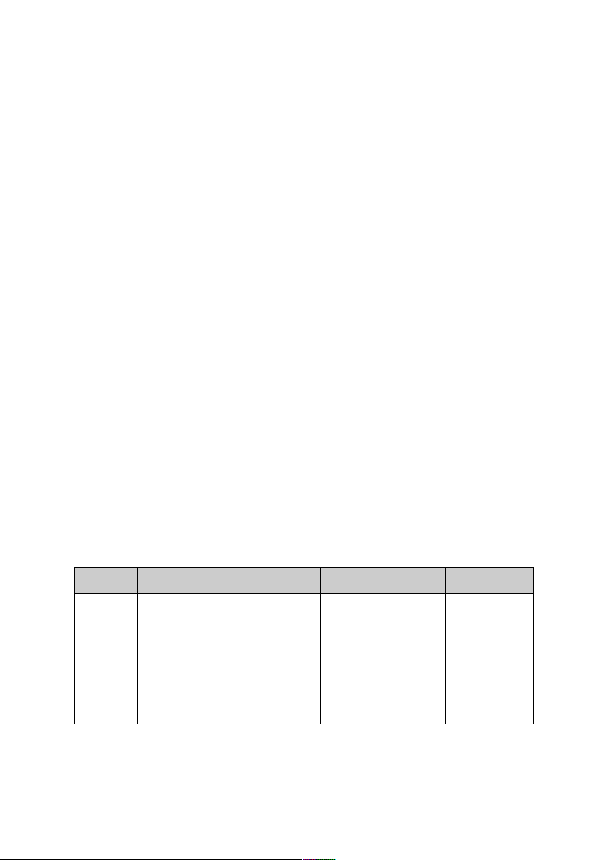
1.7 Specification
1.7.1
Input1
Resolution: 18 bits
Sampling Rate: 5 times / second
Maximum Rating: -2 VDC minimum, 12 VDC maximum (1 minute for mA input)
Temperature Effect: 1.5uV/°C for all inputs except mA input, ±3.0uV/°C for mA input
Sensor Lead Resistance Effect:
T/C: 0.2uV/ohm;
3-wire RTD: 2.6°C/ohm of resistance difference of two leads;
2-wire RTD: 2.6° C/ohm of resistance sum of two leads
Burn-out Current: 200nA
Common Mode Rejection Ratio (CMRR): 120dB
Normal Mode Rejection Ratio (NMRR): 55dB
Sensor Break Detection:
Sensor Open for TC, RTD and mV inputs
Sensor short for RTD input
Below 1 mA for 4-20 mA input,
Below 0.25V for 1 - 5 V input,
Unavailable for other inputs.
Sensor Break Responding Time:
Within 4 seconds for TC, RTD and mV inputs,
0.1 second for 4-20 mA and 1 - 5 V inputs.
Characteristics:
Type Range Accuracy @ 25°C Input Impedance
J -120°C to 1000°C ( -184°F to 1832°F )
K -200C to 1370 C ( -328°F to 2498°F ) ±2°C 2.2 MΩ
T -250°C to 400°C ( -418°F to 752°F ) ±2°C 2.2 MΩ
E -100°C to 900°C( -148°F to 1652°F ) ±2°C 2.2 MΩ
B 0°C to 1800°C( 32°F to 3272°F ) ±2°C( 200°C to 1800° C )
±2°C 2.2 MΩ
2.2 MΩ
Page 14 of 113
Page 15
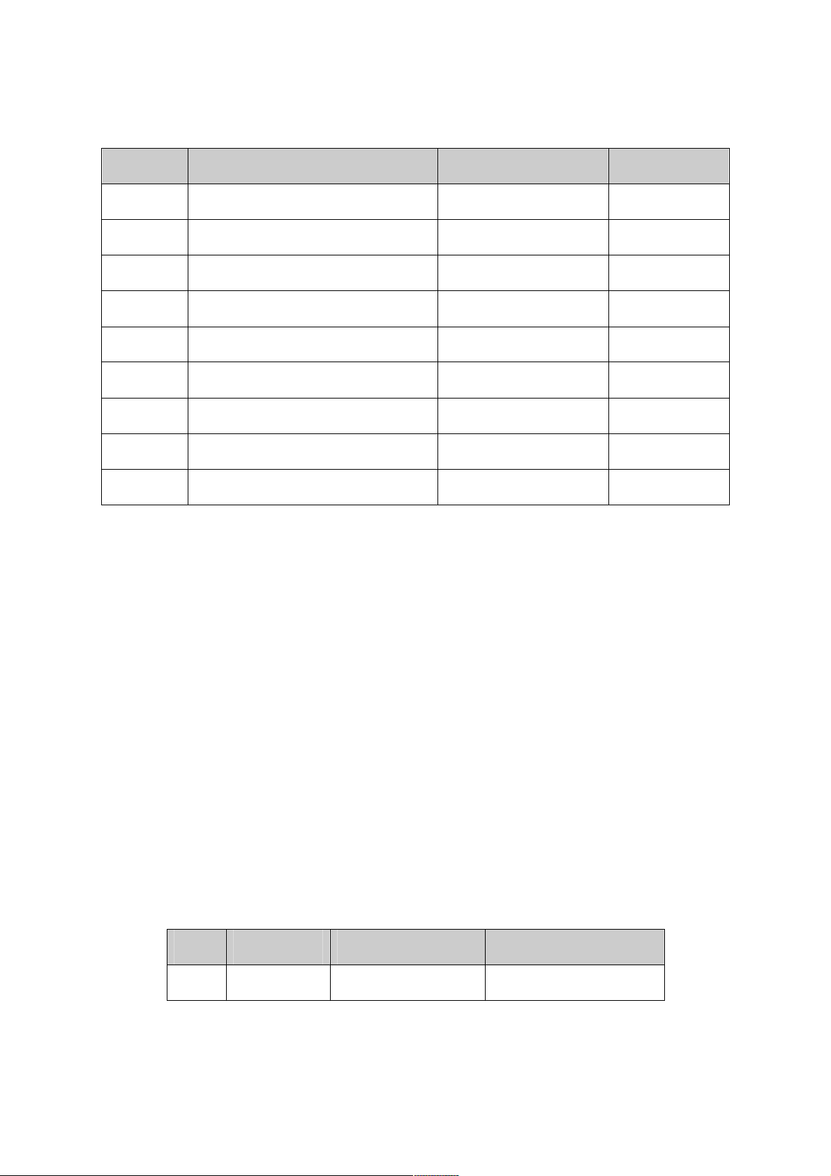
Type Range Accuracy @ 25°C Input Impedance
R 0°C to 1767.8°C( 32°F to 3214°F ) ±2°C 2.2 MΩ
S 0°C to 1767.8°C( 32°F to 3214°F ) ±2°C 2.2 MΩ
N -250°C to 1300°C( -418°F to 2372°F ) ±2°C 2.2 MΩ
L -200°C to 900°C( -328°F to 1652°F ) ±2°C 2.2 MΩ
PT100(DIN) -210°C to 700°C ( -346°F to 1292°F ) ±0.4°C 1.3KΩ
PT100(JIS) -200°C to 600°C( -328°F to 1112°F ) ±0.4°C 1.3Ω
mV -8mV to 70mV ±0.05% 2.2 MΩ
mA -3mA to 27mA ±0.05% 70.5Ω
V -1.3V to 11.5V ±0.05% 302KΩ
Table 1-1. Input 1 Characteristics
1.7.2
Input2
Resolution: 18 bits
Sampling Rate: 5 times / second
Maximum Rating: -2 VDC minimum, 12 VDC maximum (1 minute for mA input)
Temperature Effect: 1.5uV/°C for all inputs except mA input, ±3.0uV/°C for mA input
Common Mode Rejection Ratio (CMRR): 120dB
Normal Mode Rejection Ratio (NMRR): 55dB
Sensor Break Detection:
Below 1 mA for 4-20 mA input,
Below 0.25V for 1 - 5 V input,
Unavailable for other inputs.
Sensor Break Responding Time: 0.5 Seconds
Characteristics:
Type Range Accuracy @ 25°C Input Impedance
CT94-1 0.0 to 50.0 A ±2% of Reading ±0.2A
302KΩ
Page 15 of 113
Page 16

Type Range Accuracy @ 25°C Input Impedance
1.7.3
1.7.4
mA -3mA to 27mA
V -1.3V to 11.5V
±0.05% 70.5Ω+(0.8V/Input Current)
±0.05% 302KΩ
Table 1-2. Input 2 Characteristics
Input3 (Event Input)
Logic Low: -10V minimum, 0.8V maximum.
Logic high: 2V minimum, 10V maximum
External pull-down Resistance: 400 KΩ maximum
External pull-up Resistance: 1.5 MΩ minimum
Functions: Select second set point and/or PID, Reset alarm 1 and/or alarm 2,
Disable output 1 and/or output 2, Remote lockout.
Output1/Output2
Relay Rating: 2A/240 VAC, life cycles 200,000 for Resistive load
Pulsed Voltage:
Source Voltage 5V, current limiting resistance 66Ω
Linear Output Characteristics:
Type Zero Tolerance Span Tolerance Load Capacity
4 to 20mA
0 to 20mA
3.8-4 mA 20-21 mA 500 Ω max
0 mA 20-21 mA 500 Ω max
0 to 5V 0 V 5 -5.25 V 10KΩ min
1 to 5V 0.95 to 1V 5 -5.25 V 10KΩ min
0 to 10V 0 V 10 - 10.5 V 10KΩ min
Table 1-3. Output Characteristics
Linear Output
Resolution: 15 bits
Output Regulation: 0.01 % for full load change
Output Settling Time: 0.1 sec. (stable to 99.9 %)
Isolation Breakdown Voltage: 1000 VAC
Page 16 of 113
Page 17
Temperature Effect: ±0.0025 % of SPAN /°C
Triac (SSR) Output
Rating: 1A / 240 VAC
Inrush Current: 20A for 1 cycle
Min. Load Current: 50 mA RMS
Max. Off-state Leakage: 3 mA RMS
Max. On-state Voltage: 1.5 V RMS
Insulation Resistance: 1000 MΩ minimum at 500 VDC
Dielectric Strength: 2500 VAC for 1 minute
Type Tolerance Maximum Output Current Ripple Voltage Isolation Barrier
20V ±0.5 V 25 mA 0.2 Vp-p 500 VAC
12V ±0.3 V 40 mA 0.1 Vp-p 500 VAC
5V ±0.15 V 80 mA 0.05 Vp-p 500 VAC
Table 1-4. SSR Output Characteristics
1.7.5
1.7.6
Alarm 1/ Alarm 2
Alarm 1 Relay: Form A or Form B, Max. Rating 2A/240VAC, life cycles 100,000 for
resistive load.
Alarm 2 Relay: Form A, Max. Rating 2A/240VAC, life cycles 200,000 for resistive load.
Alarm Mode: Normal, Latching, Hold, Latching / Hold.
Dwell Timer: 0 - 6553.5 minutes
Alarm Functions: Dwell timer, Deviation High / Low Alarm, Deviation Band High / Low
Alarm, PV1 High / Low Alarm, PV2 High / Low Alarm, PV1 or PV2 High
/ Low Alarm, PV1-PV2 High / Low Alarm, Loop Break Alarm, Sensor
Break Alarm.
Control Mode
Output 1: Reverse (heating) or direct (cooling) action
Output 2: PID cooling control, cooling P band 1~255% of PB
ON-OFF: 0.1 - 100.0(F) hysteresis control (P band = 0)
P or PD: 0 - 100.0 % offset adjustment
Page 17 of 113
Page 18

PID: Fuzzy logic modified Proportional band 0.1 ~ 900.0°F, Integral time: 0 - 1000
Seconds, Derivative time 0 - 360.0 seconds
Cycle Time: 0.1 - 100.0 seconds
Manual Control: Heat (MV1) and Cool (MV2)
Auto-tuning: (MV2) Cold start and warm start
Self-tuning: Select None and YES
Failure Mode: Auto-transfer to manual mode while sensor break or A-D converter damage
Sleep Mode: Enable or Disable
Ramping Control: 0 - 900.0°F/minute or 0 - 900.0°F/hour ramp rate
Power Limit: 0 - 100 % output 1 and output 2
Pump / Pressure Control: Sophisticated functions provided
Remote Set Point: Programmable range for voltage or current input
Differential Control: Control PV1-PV2 at set point
1.7.7
Digital Filter
Function: First Order
Time Constant: 0, 0.2, 0.5, 1, 2, 5, 10, 20, 30, 60 seconds programmable
Page 18 of 113
Page 19
2 Installation and Wiring
Some times Dangerous voltages capable of causing death are present in this instrument. Before
doing installation or any troubleshooting procedures the power to the equipment must be switched off and
isolated. Units suspected of being faulty must be disconnected and removed to a properly equipped
workshop for testing and repair. Component replacement and internal adjustments must be made by a
qualified maintenance person only.
To minimize the possibility of fire or shock hazards, do not expose this instrument to rain or
excessive moisture
Do not use this instrument in areas under hazardous conditions such as excessive shock,
vibration, dirt, moisture, corrosive gases or oil. The ambient temperature of the areas should not
exceed the maximum rating specified in the specification
2.1 Unpacking
Upon receipt of the shipment remove the unit from the carton and inspect the unit for
shipping damage. If any damage found then contact local representative immediately. Note the
model number, serial number for future reference when corresponding with our service center. The
serial number (S/N) is labeled on the box and the housing of Paperless Recorder
Remove stains from this equipment using a soft, dry cloth. Do not use harsh chemicals,
volatile solvents such as thinner or strong detergents to clean the equipment in order to avoid
deformation.
The Paperless Recorder is designed for indoor use and not in any hazardous area. It
should be kept away from shock, vibration, and electromagnetic fields such as variable frequency
drives, motors and transformers. It is intended to operate under the following environmental
conditions.
Environmental Parameter Specification
Operating Temperature 0°C to 50 °C
Humidity 20% to 90% RH(Non-condensing)
Altitude 2000 M Maximum
Table 2-1.Environmental Specification
Page 19 of 113
Page 20

2.2 Input Output Wiring Connection
2.2.1
2.2.2
Wiring Precautions
Sometimes Dangerous voltages capable of causing death are present in this
instrument. Before doing installation or any troubleshooting procedures the power to the equipment
must be switched off and isolated. Units suspected of being faulty must be disconnected and
removed to a properly equipped workshop for testing and repair. Component replacement and
internal adjustments must be made by a qualified maintenance person only.
Utmost Care must be taken to ensure that the maximum voltage rating specified on
the label is not exceeded.
It is recommended to use an external fuse or an external switch rated at 2A/250
VAC for panel mount type wiring.
The tightening torque on the Screw terminals should not exceed 0.4 N-m (3.6 Lb-in
or 4.0 Kg F-cm).
Except Thermocouple Wiring, all other wires used to be Standard Copper
Conductor With maximum Gauge of 18AWG
Grounding must be connected prior to turning on the Equipment with minimum of
1.6mm diameter conductor for protective grounding.
PID Control Module
This is a single loop PID Control Module which consists of Universal Input.
The Modules needs to be inserted to the rear slots or removed from the rear slots at
the Power OFF condition. Failure to do so may cause damage to the module or device or
both. The Device will automatically detect the Module at Power ON, once it is inserted in to the rear
slots.
The Module output can be configured by using the configuration Menu. The configuration
Menu can be reached by pressing Menu and then pressing More and then pressing Config key. It
will display a tree type configuration layout for easy user configuration. By using Up/Down Key and
Enter Key, PID Controller and Profile configuration window can be reached. In this window the user
can configure the Controller parameters and profiles of PID Control Module. The user can select the
desired output type and other parameters for analog output in this window.
Page 20 of 113
Page 21
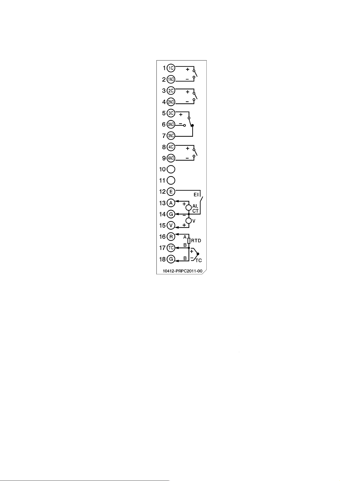
Figure
The IO Mo
is ON. This should be carried out in the Power OFF Condition only.
For removing the IO Modules,
screws, after that press the lock on
to remove it. Failing to do so will damage the IO Card. Please follow
user manual
The Maximum Torque for the metal screw is 3Kg
Torque for the plastic
Calibration should be carried out by a qualified Engineer with qualified equipments
Thermocouple inputs requires 1 hour initial warm up time during initial setup.
dules should not be removed or Inserted to the device when the Power
First remove the metal screws then
the top and bottom of the Card and
cm (2.6in
Note:
2-1.Process Control Card Wiring Diagram
plastic
for more information.
screw is 0.8Kgf-cm (.7in-lb).
only.
remove the
pull
the Recorder
-
-lb) and the Maximum
Page 21 of 113
Page 22
3 Process Control Card Features
This Chapter will explain the features of the Process Control Card.
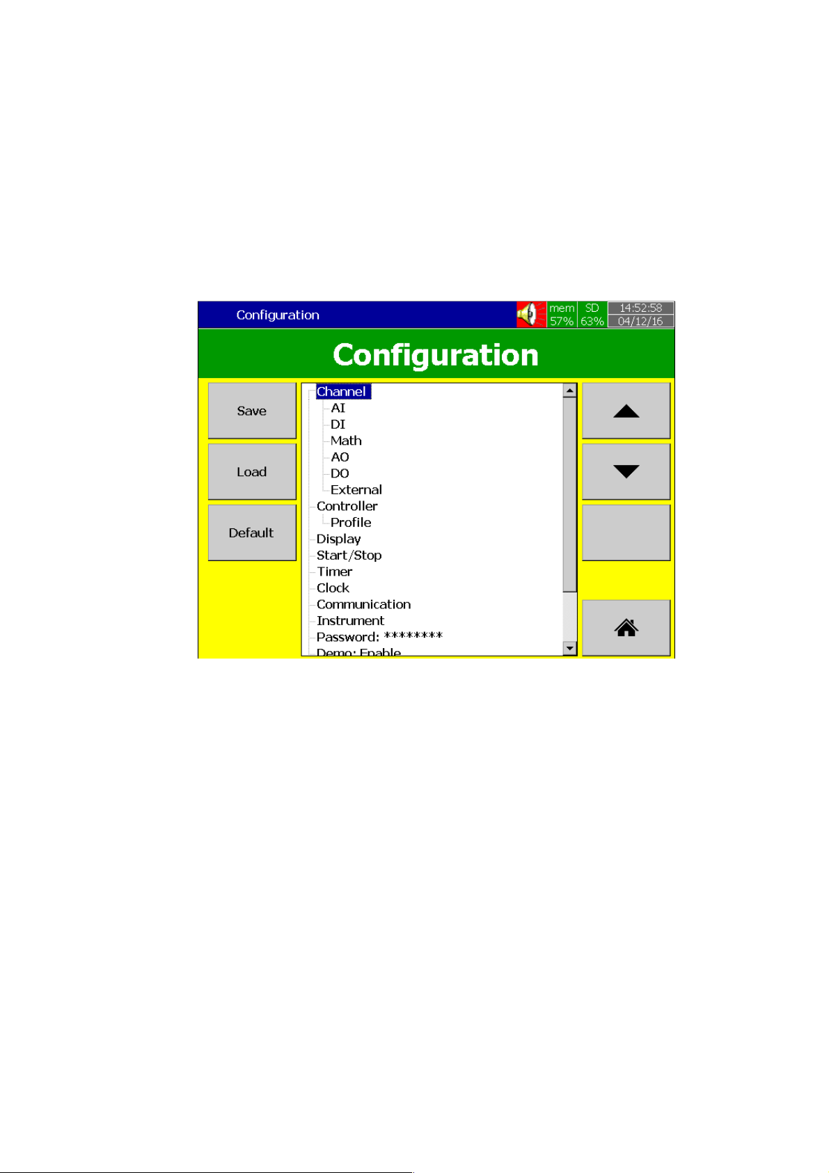
3.1 Configuration
The Process Control Card can be configured by using the tree type configuration layout
of the Paperless Recorder easily. This is much useful for the user to configure all necessary
configurations without missing any configuration.
3.2 Controller
The PID Module includes PID Controller function in the Paperless recorder and log the
data .The PID Control module is used to control the process.
3.3 Ramp & Dwell Function
The PID Control Module includes Ramp & Dwell function. It is useful to control the process
with varying set point time to time. There are 50 different Profiles can be configured with 32
Segments/Profile with the limit of 1000 Segments totally.
3.4 On Field Calibration
The Device allows the user to do on field calibration for the device. No need to send the
device to factory for Calibration
Figure 3-1.Configuration Layout
Page 22 of 113
Page 23
4 Process Control Card Functions
This Section will explain the functions of Process Control Card. The user can configure the
device as per their requirement by using the user friendly configuration menu.
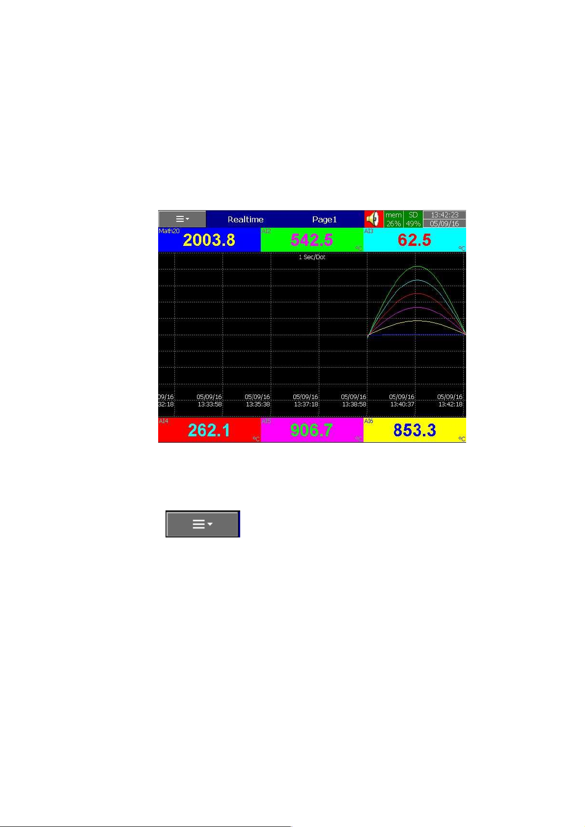
The below is the home screen of paperless recorder. This screen will be displayed when
the device powered on.
4.1 Menus
Press Soft key to access the menu in the furnace controller. The below
menu screen will show the available menus.
Figure 4-1.Home Screen
Page 23 of 113
Page 24
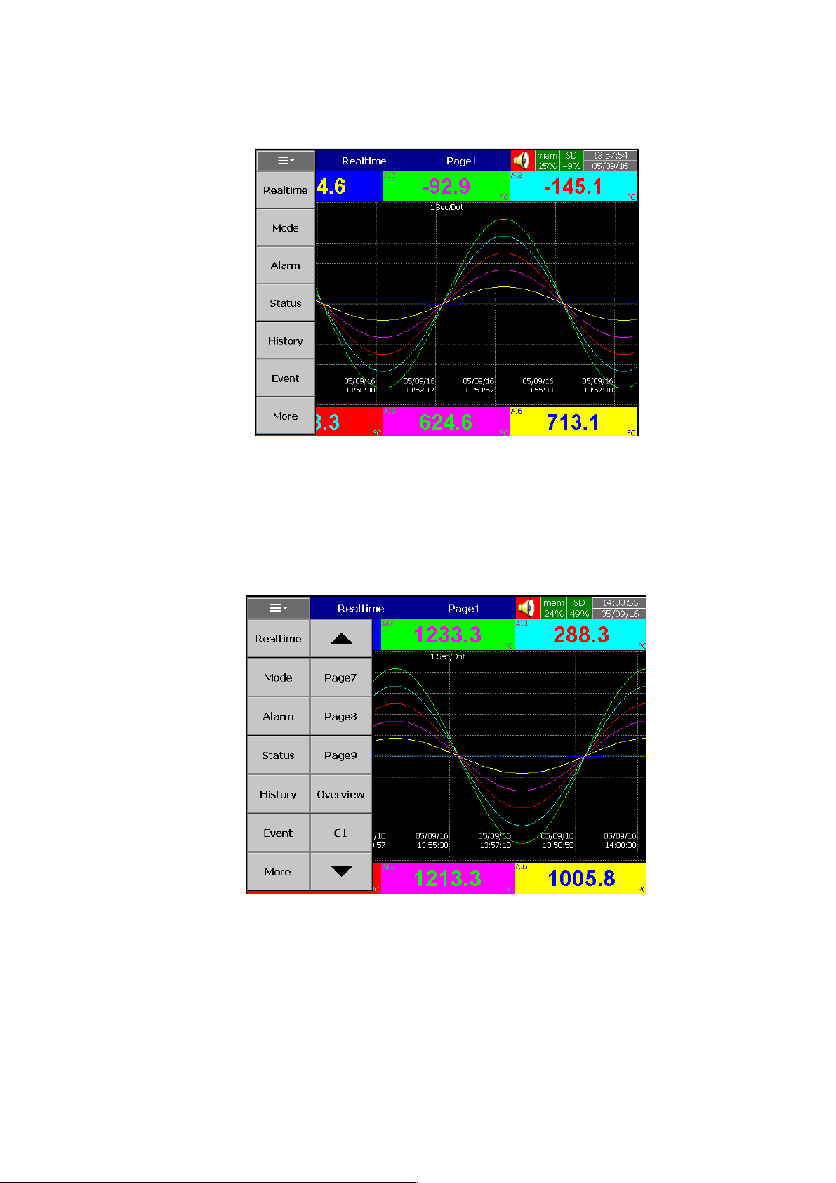
Figure 4-2.Menu Screen
Press Real time to access the real time trend display pages of the furnace controller.
Press the Page no to view the respective display pages. Press Overview to view the digital display
of all channels. Press C1 to view the PID Controller Module display.
Figure 4-3.Real Time Menu
Page 24 of 113
Page 25
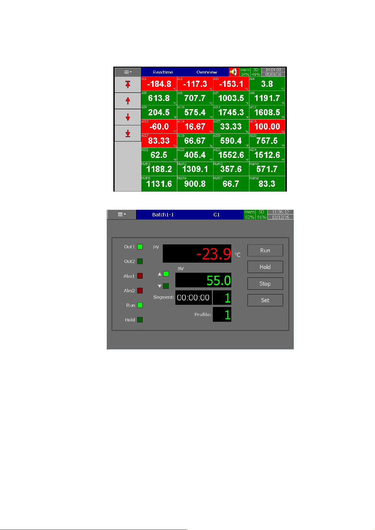
Figure 4-4.Overview Display
Figure 4-5.PID Controller Module Display
Press Mode to access the menu for different display modes. The user can select the
desired display mode to display as per their requirements like trend, Bar, Digit or Mix mode.
Page 25 of 113
Page 26
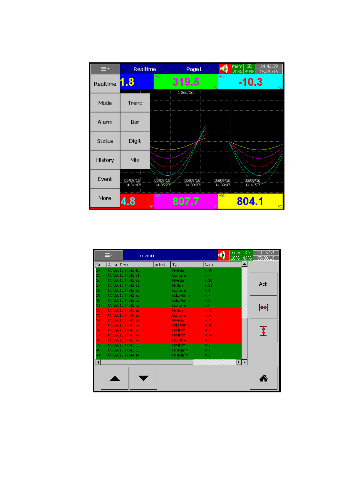
Figure 4-6.Display Modes
Press Alarm to view Real time Alarms and acknowledge using Ack key.
Figure 4-7.Real Time Alarms
Page 26 of 113
Page 27
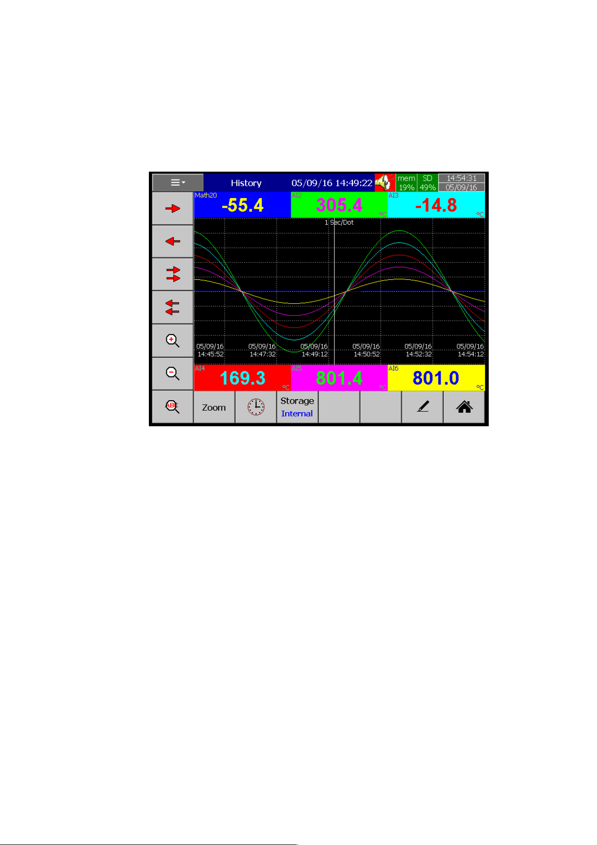
Press History to access the historical data of the individual pages and do the remarking.
The user can write their own comments by using Handwriting function .This is explained in detail in
the respective Chapter.
Figure 4-8.Historical Data Screen
Press Event to access the Historical Event and Reports from Internal and External
memory. Press Storage to toggle between internal memory and External Memory like SD Card or
USB Disk.
Page 27 of 113
Page 28
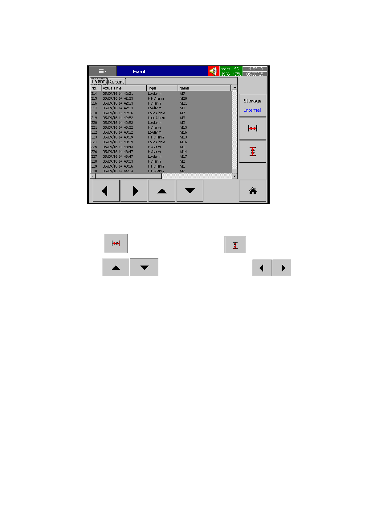
Figure 4-9.Event History
Press Key to Scroll Page Horizontally and Key to Scroll Page Vertically.
Press Keys to page Up and Down. Press Key to
switch between Reports and Events.
In Report display press Mode to display the reports in Daily, Weekly, Monthly and List
Modes.
Page 28 of 113
Page 29
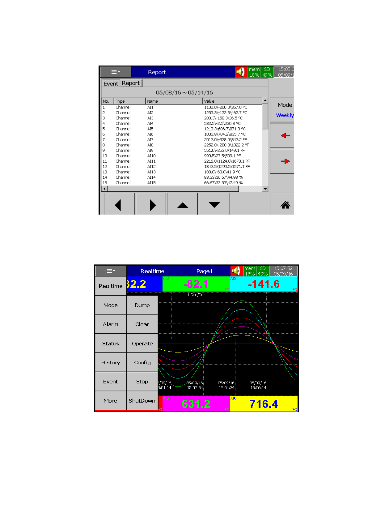
Figure 4-10.Report Screen
Press More to access more menus like dump, Clear, Operate, Config, Start/Pause, Shut
down Menus.
Figure 4-11.More Menu
Page 29 of 113
Page 30
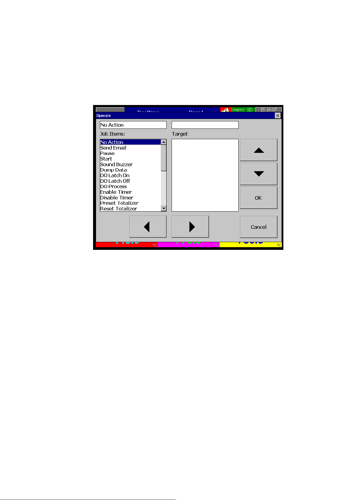
Press Dump to Dump the data from Internal memory to External memory like SD Card or
USB Disk.
Press Clear to Clear all the data in Internal memory.
Press Operate to Operate the desired job from the list.
Figure 4-12.Operate Menu
Press Config to access Tree type Configuration Lay out and perform configuration as per
the desired application.
Page 30 of 113
Page 31
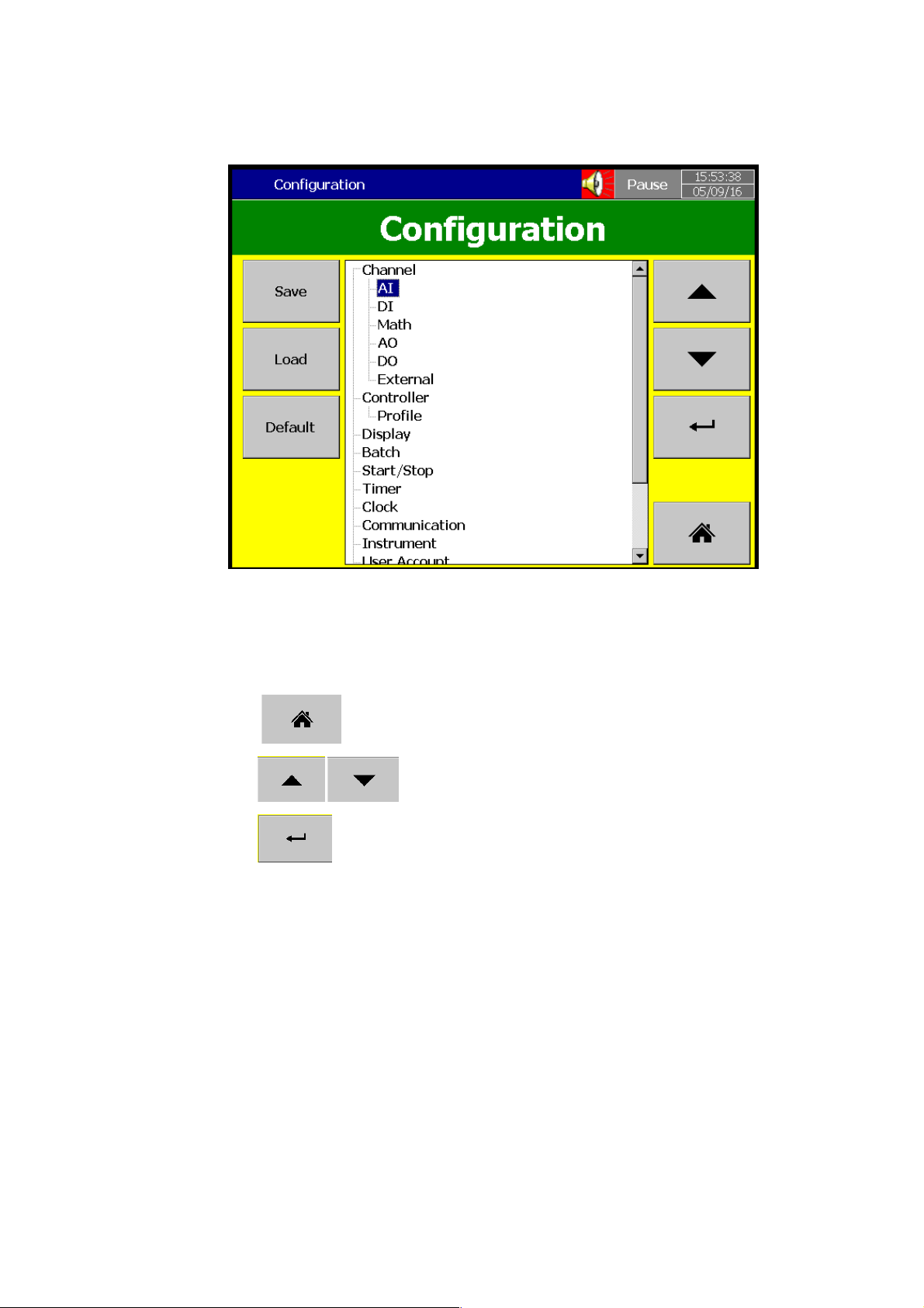
Figure 4-13.Configuration Layout
Press Save to save the configuration to SD Card or USB Device. Press Load to load the
configuration from SD Card or USB Disk.
Press Default to load the default configuration from Internal memory.
Press key to go to home page.
Press Keys to move Up and Down to select the desired menu.
Press Key to Enter to the Selected Menu.
Press Start/Stop to Start and Stop logging. The status will be shown in the Status bar on
the top of the screen.
Press Shut down to Stop and Shut down the Furnace controller.
Page 31 of 113
Page 32
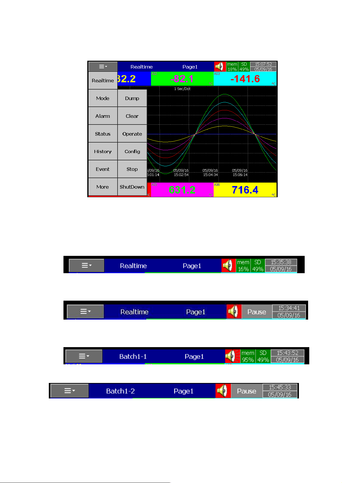
4.2 Status Bar
The Status bar will be shown on top of every page. This will show the status of the memory,
Alarm, logging status with real time Date and Time of the System.
Figure 4-14.More Menu
Figure 4-15.Status Bar During Logging
Figure 4-16.Status Bar During Logging Stopped
Figure 4-17.Status Bar during Logging with Batch function
Figure 4-18.Status Bar During Logging Stopped with Batch Function
Page 32 of 113
Page 33
4.3 Process Control Card Configuration
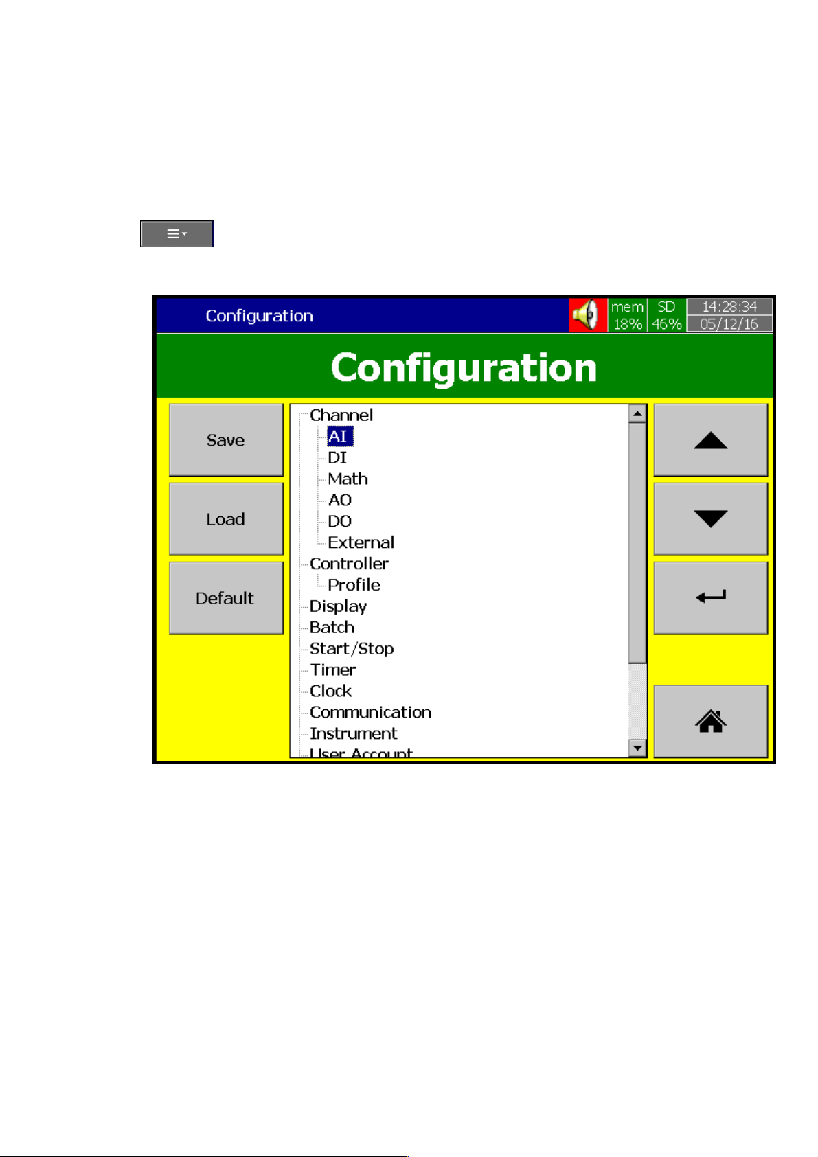
This Section will explain the configuration for Process Control Card functions. Press
(Menu) and then press More then press Config to Enter to Configuration Screen. A
Tree type configuration will be displayed for the easy configuration. In addition to that Save Load,
Default and Home Soft keys also available.
Figure 4-19.Tree Type Configuration Layout
Soft Keys
The below Soft Keys are available for the user to configure.
Page 33 of 113
Page 34
Enter Key
Up Key
Down Key
Home Key
Various options are available to select the configuration Parameters.
The user can move the cursor up and down using the soft key and press the Enter
Soft key to Enter in to the highlighted parameter configuration
The user can touch the desired parameter in the configuration tree and press Enter
Soft key to Enter in to that parameter Configuration
The user can double touch the desired parameter in the configuration tree to Enter
in to that parameter configuration
Press Save to save the configuration to SD Card or USB Device. Press Load to load the
configuration from SD Card or USB Disk. Press Default to load the default configuration from
Internal memory.
4.3.1
Press key to return to home page.
The following section will explain the detailed explanation of configuration of the device.
Process Control Card Configuration
This section will explain the configuration of Process Control Process Control Card
Channels. The Process Control Card configuration will have two sections for configuration as below
Controller
Profile
Page 34 of 113
Page 35
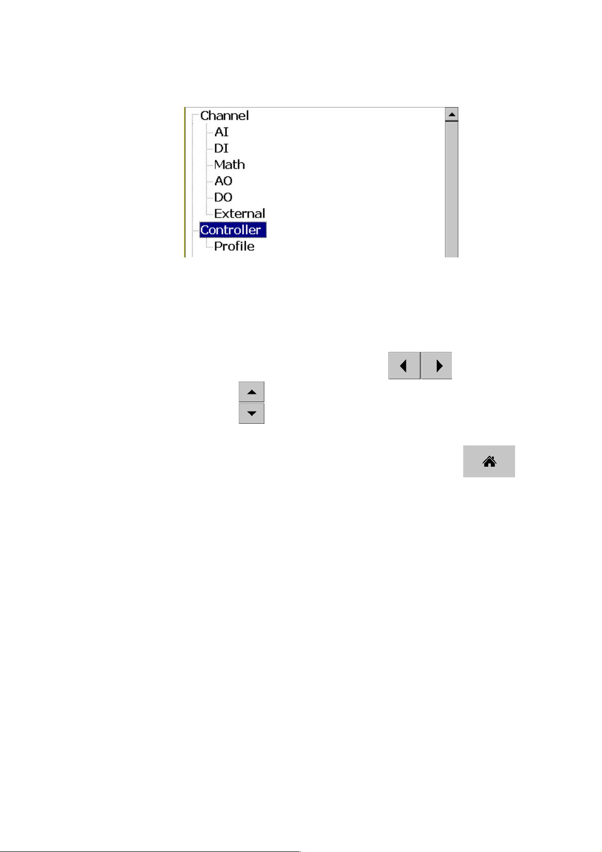
4.3.1.1 Controller
Press Controller and press Enter Key to Entering in to the Process Control Card
controller configuration. Initially it displays C1 as the first controller configuration. Use the
navigational keys to select the next Controller Channels .Use the key move to
other Controller Channels. Use key to move between the different controller Configuration
Parameters.
After completing the configuration press Back button and then press to
return to main display and save the configuration automatically.
Figure 4-20.Process Control Card Channel Configuration
Page 35 of 113
Page 36
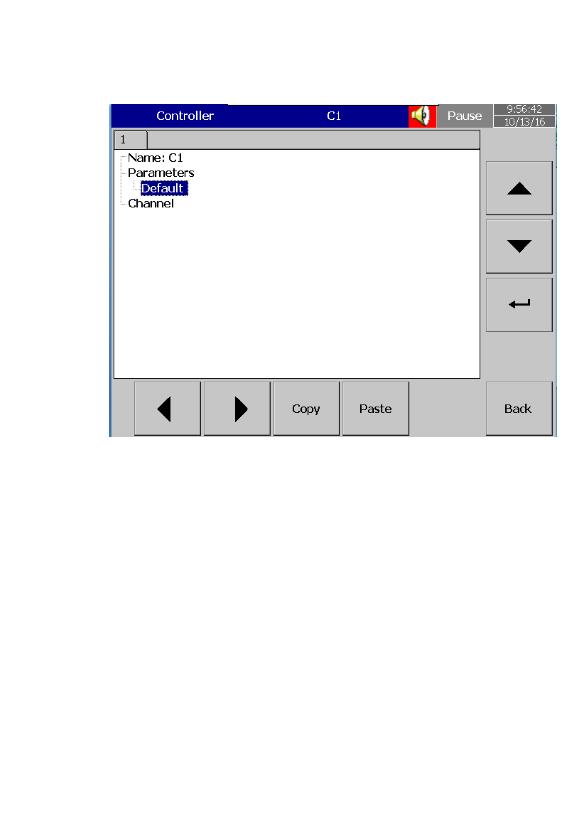
4.3.1.1.1 Name
Enable the user to define the name for each channel with the maximum limit of 18
Characters.
Select “Name”, then Press “Enter”, soft key, a keyboard with several keys appears. Press
“Shift” to select special characters. Press “Caps” to select capital letters. Press soft key “OK” after
entering a new channel name.
4.3.1.1.2 Parameter
This will allow the user to configure the PID Control function on the Process Control Card.
Press Parameter and then press Enter Soft key to access the parameter configuration table. In
the Configuration table the user can edit the parameters of the Process Control Card as per their
requirement by selecting the desired parameter using the UP DOWN key and then press the
Enter Soft Key. The Enter Soft key will be disabled for the restricted parameters.
Figure 4-21.Process Control Card Channel Configuration
Page 36 of 113
Page 37
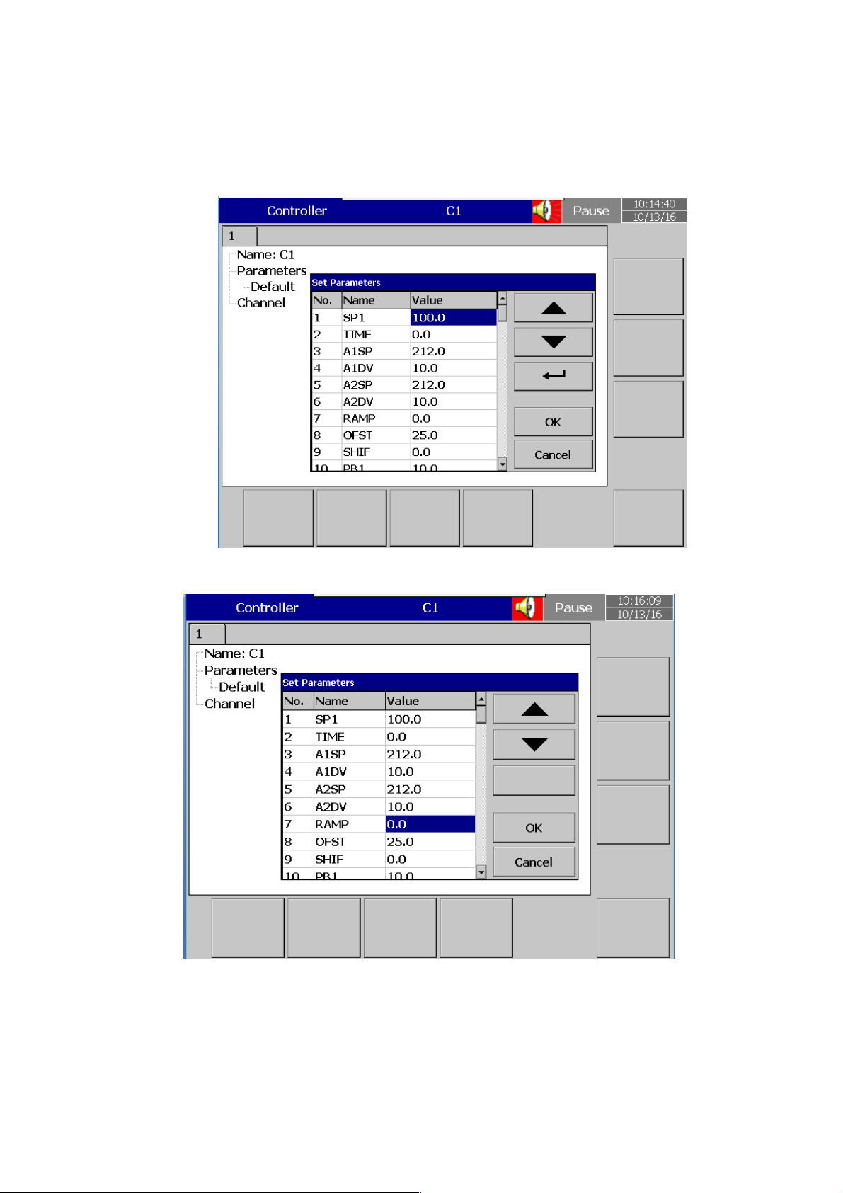
Default allows the user to load the default configuration of the Process Control
Card Parameters
Figure 4-22.Process Control Card Configuration Window
Figure 4-23.Process Control Card Configuration Window for Read only Parameter
Page 37 of 113
Page 38

The below table shows the list of parameters available in the Process Control Card for PID
C
C
C
C
C
C
C
C
C
C
C
C
Control function.
Parameter
Parameter Description
Notation
SP1 Set point 1 SP1L
TIME Dwell Time
A1SP Alarm 1 Set point
A1DV
Alarm 1 Deviation
Value
A2SP Alarm 2 Set point
A2DV
Alarm 2 Deviation
Value
Range
Low*B
*B1
-200.0°
(-360.0
*B1
-200.0°
(-360.0
0
°F)
°F)
Range High*B
SP1H
6553.5
*B1
200.0°
(360.0
°F)
*B1
200.0°
(360.0
°F)
Default
Value*C
100.0° C
(212.0°F)
0.0
100.0° C
(212.0° F)
10.0°
(18.0
°F)
100.0°
(212.0
°F)
10.0°
(18.0
°F)
Unit*E
PV
minut
e
*E1
*E1
*E2
*E2
RAMP
Ramp
OFST
REFC
Offset Value for P
Reference Constant for
Specific Function
Rate
control
SHIF PV1 Shift (offset) Value
PB1
TI1
Integral Time 1 Value
Proportional Band 1
Value
-200.0°
(-360.0
0
0
0
0
0
°F)
500.0°
(900.0
100.0
200.0°
(360.0
500.0°
(900.0
1000
60
°F)
°F)
°F)
0.0
25.0
2
0.0
PV1
10.0°
(18.0
°F)
100
Sec
*E3
%
PV
Page 38 of 113
Page 39

Parameter
C
C
C
C
C
C
Notation
TD1
Derivative Time 1 Value
Parameter Description
Range
Low*B
0
Range High*B
360.0
Default
Value*C
25.0
Sec
Unit*E
CPB
DB
Cooling Proportional
Band Value
Heating-Cooling
Band
SP2 Set point 2
PB2
TI2
Integral Time 2 Value
TD2
Derivative Time 2 Value
O1HY
A1HY
Proportional Band 2
Value
Output 1 ON-OFF
Control
Hysteresis
Hysteresis Control of
Alarm 1
Dead
1
-36.0
*B2
0
0
0
0.1
0.1
255
36.0
*B2
500.0°
(900.0
°F)
1000
360.0
55.6°
(100.0
°F
100
37.8°
(100.0
10.0°
(18.0
100
25.0
0.1
0
°F
°F
Sec
Sec
PV
10.0°
(18.0
°F)
0.1
% of
PB
% of
PB
PV
PV
*E1
A2HY
Hysteresis Control of
Alarm 2
PL1 Output 1 Power Limit
PL2 Output 2 Power Limit
FUNC
COMM
Function Complexity
Level
Communication
Interface Type
0
0
0.1
0
0
*B3
*B4
(18.0
100
100
*B3
1
*B4
8
°F)
0.1
100
100
1
1
10.0°
*E2
%
%
Page 39 of 113
Page 40

Parameter
C
C
Notation
Parameter Description
Range
Low*B
Range High*B
Default
Value*C
Unit*E
PROT
ADDR
BAUD
DATA
PARI
STOP
AOFN
Analog Output Function
COMM Protocol
Selection
Address Assignment
Digital COMM
Baud Rate of Digital
COMM
Data Bit count of Digital
COMM
Parity Bit of Digital
COMM
Stop Bit Count of
Digital
COMM
*B5
0
of
0
0
1
*B7
0
*B8
0
*B9
0
*B10
*B11
*B5
0
255
*B7
9
*B8
1
*B9
2
*B9
1
*B11
7
0
5
1
0
0
0
IN1
IN1U
IN1 Unit Selection
DP1
IN1 Sensor Type
Selection
IN1 Decimal Point
Selection
IN1L IN1 Low Scale Value
IN1H
IN1 High Scale Value
SP1L
SP1H
SP1 Low Scale Value
SP1 High Scale
Value
*B12
0
*B13
0
*B14
0
-19999
-19999
-19999 45536
-19999
*B12
17
*B13
2
*B14
3
45536
45536
45536
1
(0)
0
(1)
1
0
1000
0.0°
(32.0
°F)
1000.0°
(1832.0
°F)
PV
PV
*E5
*E5
Page 40 of 113
Page 41

Parameter
Notation
Parameter Description
Range
Low*B
Range High*B
Default
Value*C
Unit*E
IN2
IN2U
IN2 Unit
DP2
IN2L
IN2H
IN2 High Scale
EIFN
OUT1
O1TY
CYC1
Output 1 Cycle
O1FT
IN2 Signal Type
IN2 Decimal Point
IN2 Low Scale
Event Input
Output 1
Output 1 Signal
Output 1 Failure
Transfer
Selection
Selection
Selection
Function
Function
Mode
Value
Value
Type
Time
*B13
0
20
*B13
0
*B14
0
-19999
-19999
*B16
0
*B17
0
*B18
0
0.1
*B18
0
2
3
9
1
8
0
*B15
*B13
*B14
45536
45536
*B16
*B17
*B18
100.0
*B18
1
2
1
0
1000
1
0
0
18.0
-0.1
*E6
*E6
Sec
%
OUT2
O2TY
CYC2
O2FT
A1FN
A1MD
A1FT
A2FN
Alarm 2
Output 2
Output 2 Signal
Output 2 Cycle
Function
Type
Time
Output 2 Failure
Transfer
Alarm 1
Mode
Function
Alarm 1 Operation
Mode
Alarm 1 Failure Transfer
Mode
Function
0.1
-0.1
*B18
0
0
*B18
0
0
*B19
100.0
*B22
0
15
*B23
0
3
*B24
0
1
*B22
0
15
*B18
*B18
100.0
*B22
*B23
*B24
*B22
*B19
0
0
18.0
-0.1
2
0
1
2
Sec
%
Page 41 of 113
Page 42

Parameter
Notation
Parameter Description
Range
Low*B
Range High*B
Default
Value*C
Unit*E
A2MD
A2FT
SELF
SLEP
PVMD
PV Mode
SP2F
FILT
SPMD
SEL1
Select 1'st
Alarm 2 Operation
Mode
Alarm 2 Failure Transfer
Mode
Self Tune Function
Selection
Sleep mode Function
Selection
Selection
Format of Set point 2
Value
Filter Damping Time
Constant of PV
Set point Mode
Selection
Parameter
*B23
0
3
*B24
0
1
*B25
0
1
*B26
0
1
*B27
0
3
*B28
0
1
*B29
0
9
*B30
0
5
*B31
0
18
*B23
*B24
*B25
*B26
*B27
*B28
*B29
*B30
*B31
0
1
0
0
0
0
2
0
0
SEL2
SEL3
SEL4
Select 4'th
SEL5
Select 5'th
DRIF
AD0
ADG
Select 2'nd
Select 3'rd
Parameter
Parameter
Parameter
Parameter
Warm-up Drift
Calibration Factor
A to D Zero
Calibration
Coefficient
A to D Gain
Calibration
Coefficient
*B31
0
*B31
0
*B31
0
*B31
0
-360
-199.9
18
18
18
18
-5.0°C
*B31
*B31
*B31
*B31
5.0°C
360
199.9
0
0
0
0
°C
Page 42 of 113
Page 43

Parameter
Notation
Parameter Description
Range
Low*B
Range High*B
Default
Value*C
Unit*E
V1G
CJTL
CJG
REF1
SR1
MA1G
REF2
Voltage Input1 Gain
Calibration Coefficient
Cold Junction Low
Temperature Calibration
Coefficient
Cold Junction Gain
Calibration Coefficient
Reference Voltage1
Calibration Coefficient for
RTD1
Serial Resistance 1
Calibration Coefficient for
RTD1
mA input 1 Gain Calibration
Coefficient
Reference Voltage2
Calibration Coefficient for
RTD2
-199.9
-5.0°C
-199.9
-199.9
-199.9
-199.9
-199.9
199.9
40.0°C
199.9
199.9
199.9
199.9
199.9
°C
SR2
V2G
MA2G
O2L
O2H
SIG1
Serial Resistance 2
Calibration Coefficient for
RTD2
Voltage input 2 Gain
Calibration Coefficient
mA input 2 Gain Calibration
Coefficient
Output 2 Low Calibration
Coefficient
Output 2 High
Calibration
Point 1 Signal Value of
Special Sensor
Coefficient
-199.9
-199.9
-199.9
0
0
-19999
199.9
199.9
199.9
360.0
900.0
45536
Page 43 of 113
Page 44

Parameter
Notation
Parameter Description
Range
Low*B
Range High*B
Default
Value*C
Unit*E
IND1
SIG2
IND2
SIG3
IND3
SIG4
IND4
SIG5
Point 1 Indication Value
of Special Sensor
Point 2 Signal Value of
Special Sensor
Point 2 Indication Value
of Special Sensor
Point 3 Signal Value of
Special Sensor
Point 3 Indication Value
of Special Sensor
Point 4 Signal Value of
Special Sensor
Point 4 Indication Value
of Special Sensor
Point 5 Signal Value of
Special Sensor
-19999
-19999
-19999
-19999
-19999
-19999
-19999
-19999
45536
45536
45536
45536
45536
45536
45536
45536
PV
PV
PV
PV
IND5
SIG6
IND6
SIG7
IND7
SIG8
IND8
Point 5 Indication Value
of Special Sensor
Point 6 Signal Value of
Special Sensor
Point 6 Indication Value
of Special Sensor
Point 7 Signal Value of
Special Sensor
Point 7 Indication Value
of Special Sensor
Point 8 Signal Value of
Special Sensor
Point 8 Indication Value
of Special Sensor
-19999
-19999
-19999
-19999
-19999
-19999
-19999
45536
45536
45536
45536
45536
45536
45536
PV
PV
PV
PV
Page 44 of 113
Page 45

Parameter
Notation
Parameter Description
Range
Low*B
Range High*B
Default
Value*C
Unit*E
SIG9
IND9
TYPE
DATE
NO
HOUR
HRLO
Fractional Hour
ERR1
ERR2
Point 9 Signal Value of
Point 9 Indication Value
of Special Sensor
Signal Type of Special
Manufacturing
Working Hour
Historical
Special Sensor
Sensor
Date of
Product
Serial Number of
Product
Value
Value
Error
Record
1
Historical
Error
Record 2
-19999
-19999
0
0
1
0
0
0
0
45536
45536
3
3719
999
65535
0.9
FFFF
FFFF
PV
0
0
Hour
0.1Hour
DELI
BPL1
BPL2
PVHI
PVLO
CJCL
FILE
ASCII Input
OUT1 Bumpless
Transfer
OUT2 Bumpless
Transfer
Historical Maximum
Value of PV
Historical Minimum
Value of PV
Sense Voltage of Cold
Junction Calibration Low
Default File
Delimiter
Value
Value
Selection
0000
0
0
-19999
-19999
31.680
*B32
0
007F
100.00
100.00
45536
45536
40.320
*B32
1
000A
%
%
PV
PV
mV
Page 45 of 113
Page 46

Parameter
C
Notation
Parameter Description
Range
Low*B
Range High*B
Default
Value*C
Unit*E
PV
Current Process
SV
MV1
MV2
Current set point
Current Output 1
Current Output 2
Contains Conditional Code
ALM
of parameters Resolution
and Current Alarm Status
DV
PV1
IN1 Process
PV2
PB
TI
Current Deviation (PV-
SV)Value
IN2 Process
Current
Band
Current Integral Time
Value
Value
Value
Value
Value
Value
Proportional
Value
Value
-19999
-19999
-12600
-19999
-19999
0
0
*B33
0
0
0
45536
45536
100.00
100.00
EF7F
12600
45536
45536
500.0°
(900.0
°F)
4000
*B33
PV
PV
%
%
PV
*E5
*E6
PV
Sec
TD
EROR
PROG
MODE
CMND
JOB
Current
Time
Current Error
Program
Identification
Contains Program
Number
Number
Contains Lockout
Status code and
Current system mode
Command
Job
Derivative
Value
Code
and
Version
Password
Password
Code
0
*B34
0
*B35
0
*B36
0
0
0
1440
40
15.99
3.5
65535
65535
*B34
*B34
*B35
Sec
Page 46 of 113
Page 47
Parameter
Notation
Parameter Description
Range
Low*B
Range High*B
Default
Value*C
Unit*E
Cold Junction
-40.0
CJCT
Compensation
° C
90.0° C
Temperature
PVR
PVRH
PVRL
SPC
Current Process Rate
Value
Maximum Process Rate
Value
Minimum Process Rate
Value
Current Target Value of
set
point
-16383
-16383
-16383
-19999
16383
16383
16383
45536
PV/min
PV/min
PV/min
PV
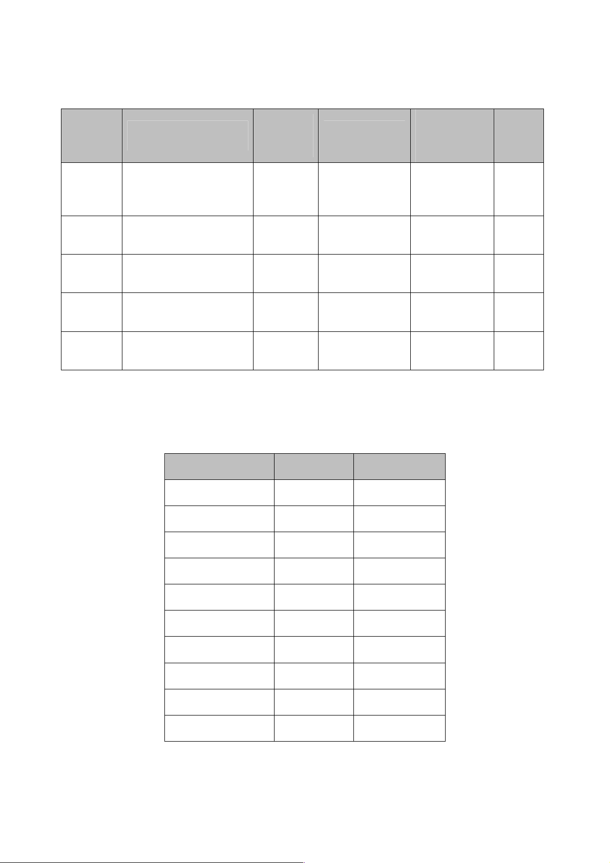
Table 4-1.PID Parameter List
*B: The ranges of some parameters are dependent on the input types. The range of IN1 and IN2 for
various input type is shown in the following table:
Input Type Range Low Rang High
°C
J_T/C -120°C(-184°F) 1000°C(1832°F)
K_T/C -200°C(-328°F) 1370°C(2498°F)
T_T/C -250°C(-418°F) 400°C(752°F)
E_T/C -100°C(-148°F) 900°C(1652°F)
B_T/C 0°C(32°F) 1820°C(3308°F)
R_T/C 0°C(32°F) 1767.8°C(3214°F)
S_T/C 0°C(32°F) 1767.8°C(3214°F)
N_T/C -250°C(-418°F) 1300°C(2372°F)
L_T/C -200°C(-328°F) 900°C(1652°F)
PT100_DN -210°C(-346°F) 700°C(1292°F)
Page 47 of 113
Page 48
Input Type Range Low Rang High
PT100_JS -210°C(-346°F) 600°C(1112°F)
CT 0 Amps 90 Amps
Linear (mA or Voltage) -19999 45536
Table 4-2.Process Control Card Input Range
*B1: Range For A1SP & A2SP
If A1FN= Range of A1SP same as range of
PV1.H,PV1.L IN1
PV2.H,PV2.L IN2
P1.2 H,P1.2 L,D1.2 H ,D1.2 L IN1,IN2
If A2FN= Range of A2SP same as range of
PV1.H,PV1.L IN1
PV2.H,PV2.L IN2
P1.2 H,P1.2 L,D1.2 H ,D1.2 L IN1,IN2
*B2: Range For SP2
If PVMD= Range of SP2 same as range of
PV1 IN1
PV2 IN2
Table 4-3.Range of A1SP
Table 4-4.Range of A2SP
P1-2,P2-1 IN1,IN2
Table 4-5.Range Of SP2
Page 48 of 113
Page 49
*B3: Display Symbol and Description of FUNC
Parameter Value Display Symbol Description
0 BASC Basic Function Mode
1 FULL Full Function Mode
Table 4-6.Mode Selection
*B4: Display Symbol and Description For COMM
Parameter Value Display Symbol Description
0 NONE No Communication Function
1 485 RS-485 Interface
2 232 RS-232 Interface
3 4-20 4-20mA Analog Retransmission Output
4 0-20 0-20mA Analog Retransmission Output
5 0-1V 0-1V Analog Retransmission Output
6 0-5V 0-5V Analog Retransmission Output
7 1-5V 1-5V Analog Retransmission Output
8 0-10V 0-10V Analog Retransmission Output
Table 4-7.Communication Mode
*B5: Display Symbol and Description For PROT
Parameter Value Display Symbol Description
0 RTU Modbus RTU Mode
1 ASCI Modbus ASCII Mode
Page 49 of 113
Page 50
Parameter Value Display Symbol Description
2 DNET Devicenet Protocol
3 PBUS Profibus Protocol
4 FBUS Fieldbus Protocol
5 ABUS Reserved
6 BNET Reserved
Table 4-8.Communication Protocol
*B7: Display Symbol and Description For BAUD
Parameter Value Display Symbol Description
0 0.3 0.3 Kbits/Second Baud Rate
1 0.6 0.6 Kbits/Second Baud Rate
2 1.2 1.2 Kbits/Second Baud Rate
3 2.4 2.4 Kbits/Second Baud Rate
4 4.8 4.8 Kbits/Second Baud Rate
5 9.6 9.6 Kbits/Second Baud Rate
6 14.4 14.4 Kbits/Second Baud Rate
7 19.2 19.2 Kbits/Second Baud Rate
8 28.8 28.8 Kbits/Second Baud Rate
9 38.4 38.4 Kbits/Second Baud Rate
Table 4-9.Communication Baud Rate
Page 50 of 113
Page 51
*B8: Display Symbol and Description For DATA
Parameter Value Display Symbol Description
0 7BIT 7 Data Bits
1 8BIT 8 Data Bits
Table 4-10.Communication Data Length
*B9: Display Symbol and Description For PARI
Parameter Value Display Symbol Description
0 EVEN Even Parity
1 ODD Odd Parity
2 NONE No Parity
Table 4-11.Communication Parity
*B10: Display Symbol and Description For STOP
Parameter Value Display Symbol Description
0 1 BIT One Stop Bit
1 2 BIT Two Stop Bits
Table 4-12.Communication Stop Bit
Page 51 of 113
Page 52
*B11: Display Symbol and Description For AOFN
Parameter Value Display Symbol Description
0 PV1 Retransmit IN1 Process Value
1 PV2 Retransmit IN2 Process Value
2 P1-2 Retransmit IN1-IN2 Difference Process Value
3 P2-1 Retransmit IN2-IN1 Difference Process Value
4 SV Retransmit Set Point Value
5 MV1 Retransmit Output1 manipulation Value
6 MV2 Retransmit Output2 manipulation Value
7 DV Retransmit Deviation(PV-SV) Value
Table 4-13 Function of AOFN
*B12: Display Symbol and Description For IN1
Parameter Value Display Symbol Description
0 J_TC J Type Thermocouple
1 K_TC K Type Thermocouple
2 T_TC T Type Thermocouple
3 E_TC T Type Thermocouple
4 B_TC B Type Thermocouple
5 R_TC R Type Thermocouple
6 S_TC S Type Thermocouple
7 N_TC N Type Thermocouple
8 L_TC L Type Thermocouple
9 PT.DN PT 100 Ohms DIN Curve
Page 52 of 113
Page 53
Parameter Value Display Symbol Description
10 PT.JS PT100 Ohms JIS Curve
11 4-20 4-20mA Linear Current Input
12 0-20 0-20mA Linear Current Input
13 0-1V 0-1V Linear Voltage Input
14 0-5V 0-5V Linear Voltage Input
15 1-5V 1-5V Linear Voltage Input
16 0-10 0-10V Linear Voltage Input
17 SPEC Special defined sensor Curve
Table 4-14 Selection of IN1 Type
*B13: Display Symbol and Description For IN1U & IN2U
Parameter Value Display Symbol Description
0 °C Degree Celsius Unit
1 °F Degree Fahrenheit Unit
2 PU Process Unit
Table 4-15.Display Unit for IN1 & IN2
*B14: Display Symbol and Description For DP1 &DP2
Parameter Value Display Symbol Description
0 NO-DP No Decimal Digit
1 1-DP One Decimal Digit
2 2-DP Two Decimal Digits
3 3-DP Three Decimal Digits
Table 4-16.Decimal Digit for DP1&DP2
Page 53 of 113
Page 54
*B15: Display Symbol and Description For IN2
Parameter Value Display Symbol Description
0 NONE IN2 No Function
1 CT Current Transformer Input
2 4-20 4-20mA Linear Current Input
3 0-20 0-20mA Linear Current Input
4 0-1V 0-1V Linear Voltage Input
5 0-5V 0-5V Linear Voltage Input
6 1-5V 1-5V Linear Voltage Input
7 0-10 0-10V Linear Voltage Input
Table 4-17.IN2 Input
*B16: Display Symbol and Description For EIFN
Parameter Value Display Symbol Description
0 NONE Event Input No Function
1 SP2 SP2 Activated to replace SP1
2 PID2 PB2,TI2,TD2 Activated to replace PB1,TI1,TD1
3 SP.P2 SP2,PB2,TI2,TD2 Activated to replace SP1,PB1,TI1,TD1
4 RS.A1 Reset Alarm 1 Output
5 RS.A2 Reset Alarm2 Output
6 R.A1.2 Reset Alarm1 & Alarm2 Output
Page 54 of 113
Page 55
Parameter Value Display Symbol Description
7 D.O1 Disable Output1
8 D.O2 Disable Output2
9 D.O1.2 Disable Output1 &Output 2
10 LOCK Lock All Parameters
Table 4-18.EIFN Function
*B17: Display Symbol and Description For OUT1
Parameter Value Display Symbol Description
0 REVR Reverse(Heating)Control Action
1 DIRT Direct(Cooling)Control Action
Table 4-19.OUT1 Action
*B18: Display Symbol and Description For O1TY & O2TY
Parameter Value Display Symbol Description
0 RELY Relay Output
1 SSRD Solid State Relay Drive Output
2 SSR Solid State Relay Output
3 4-20 4-20mA Current Module
4 0-20 0-20mA Current Module
5 0-1V 0-1V Voltage Module
6 0-5V 0-5V Voltage Module
7 1-5V 1-5V Voltage Module
8 0-10 0-10V Voltage Module
Table 4-20.OUT1 & OUT2 Type
Page 55 of 113
Page 56
*B19: Failure transfer mode for output 1 and output 2, select BPLS ( bumpless transfer ) or
0.0 ~ 100.0 % to continue output 1 and output 2 control function as the unit fails , power starts
or manual mode starts.
*B20: Display Symbol and Description For OUT2
Parameter Value Display Symbol Description
0 NONE Output 2 no function
1 COOL PID cooling control
3 DCPS DC power supply module installed
Table 4-21.OUT2 Function
*B21: Display Symbol and Description For DISF
Parameter Value Display Symbol Description
0 PV Display PV Value
1 SV Display SV Value
Table 4-22.Display Function
*B22: Display Symbol and Description For A1FN & A2FN
Parameter Value Display Symbol Description
0 NONE No alarm function
1 TIMR Dwell timer action
2 DE.HI Deviation high alarm
3 DE.LO Deviation low alarm
Page 56 of 113
Page 57
Parameter Value Display Symbol Description
4 DB.HI Deviation band out of band alarm
5 DB.LO Deviation band in band alarm
6 PV1.H IN1 process value high alarm
7 PV1.L IN1 process value low alarm
8 PV2.H IN2 process value high alarm
9 PV2.L IN2 process value low alarm
10 P1.2.H IN1 or IN2 process value high alarm
11 P1.2.L IN1 or IN2 process value low alarm
12 D1.2.H IN1 IN2 difference process value high alarm
13 D1.2.L IN1 IN2 difference process value low alarm
14 LB Loop break alarm
15 SEN.B Sensor break or A-D fails
Table 4-23. Alarm1 & Alarm 2 Function
*B23: Display Symbol and Description For A1MD & A2MD
Parameter Value Display Symbol Description
0 NORM Normal alarm action
1 LTCH Latching alarm action
2 HOLD Hold alarm action
3 LT.HO Latching & Hold action
Table 4-24.Alarm1 & Alarm2 Operation Mode
Page 57 of 113
Page 58
*B24: Display Symbol and Description For A1FT & A2 FT
Parameter Value Display Symbol Description
0 OFF Alarm Output OFF as unit Fails
1 ON Alarm Output ON as unit Fails
Table 4-25.Alarm1 & Alarm2 Failure Transfer Mode
*B25: Display Symbol and Description For SFLF
Parameter Value Display Symbol Description
0 NONE Auto tuning (Self Tune) Function disabled
1 YES Auto tuning (Self Tune) Function Enabled
Table 4-26.Auto Tuning
*B26: Display Symbol and Description For SLEP
Parameter Value Display Symbol Description
0 NONE Sleep Mode Function disabled
1 YES Sleep Mode Function Enabled
Table 4-27.Sleep Mode
*B27: Display Symbol and Description For PVMD
Parameter Value Display Symbol Description
0 PV1 Use PV1 as Process Value
1 PV2 Use PV2 as Process Value
Page 58 of 113
Page 59
Parameter Value Display Symbol Description
2 P1-2 Use PV1-PV2 Difference as Process Value
3 P2-1 Use PV2-PV1 Difference as Process Value
Table 4-28.PV Mode Selection
*B28: Display Symbol and Description For SP2F
Parameter Value Display Symbol Description
0 ACTU Setpoint2 (SP2)is an Actual Value
1 DEVI Setpoint2 (SP2) is an Deviation Value
Table 4-29.SP2 Set Point Format
*B29: Display Symbol and Description For FILT
Parameter Value Display Symbol Description
0 0 0 second time constant
1 0.2 0.2 second time constant
2 0.5 0.5 second time constant
3 1 1 second time constant
4 2 2 seconds time constant
5 5 5 seconds time constant
6 10 10 seconds time constant
7 20 20 seconds time constant
8 30 30 seconds time constant
9 60 60 seconds time constant
Table 4-30 Filter Damping Time Constant of PV
Page 59 of 113
Page 60
*B30: Display Symbol and Description For SPMD
Parameter Value Display Symbol Description
0 SP1.2 Use SP1 or SP2 (depends on EIFN) as set point
1 MIN.R Use minute ramp rate as set point
2 HR.R Use hour ramp rate as set point
3 PV1 Use IN1 process value as set point
4 PV2 Use IN2 process value as set point
5 PUMP Selected for pump control
Table 4-31 Set Point Mode Selection
*B31: Display Symbol and Description For SEL1-SEL5
Parameter Value Display Symbol Description
0 NONE No parameter put ahead
1 TIME Parameter TIME put ahead
2 A1.SP Parameter A1SP put ahead
3 A1.DV Parameter A1DV put ahead
4 A2.SP Parameter A2SP put ahead
5 A2.DV Parameter A2DV put ahead
6 RAMP Parameter RAMP put ahead
7 OFST Parameter OFST put ahead
8 REFC Parameter REFC put ahead
9 SHIF Parameter SHIF put ahead
10 PB1 Parameter PB1 put ahead
Page 60 of 113
Page 61
Parameter Value Display Symbol Description
11 TI1 Parameter TI1 put ahead
12 TD1 Parameter TD1 put ahead
13 C.PB Parameter CPB put ahead
14 DB Parameter DB put ahead
15 SP2 Parameter SP2 put ahead
16 PB2 Parameter PB2 put ahead
17 TI2 Parameter TI2 put ahead
18 TD2 Parameter TD2 put ahead
Table 4-32 SEL Selection
*B32: Display Symbol and Description For FILE
Parameter Value Display Symbol Description
0 0 Perform Default Setting by using °C File
1 1 Perform Default Setting by using °F File
Table 4-33 Default File Selection
Page 61 of 113
Page 62
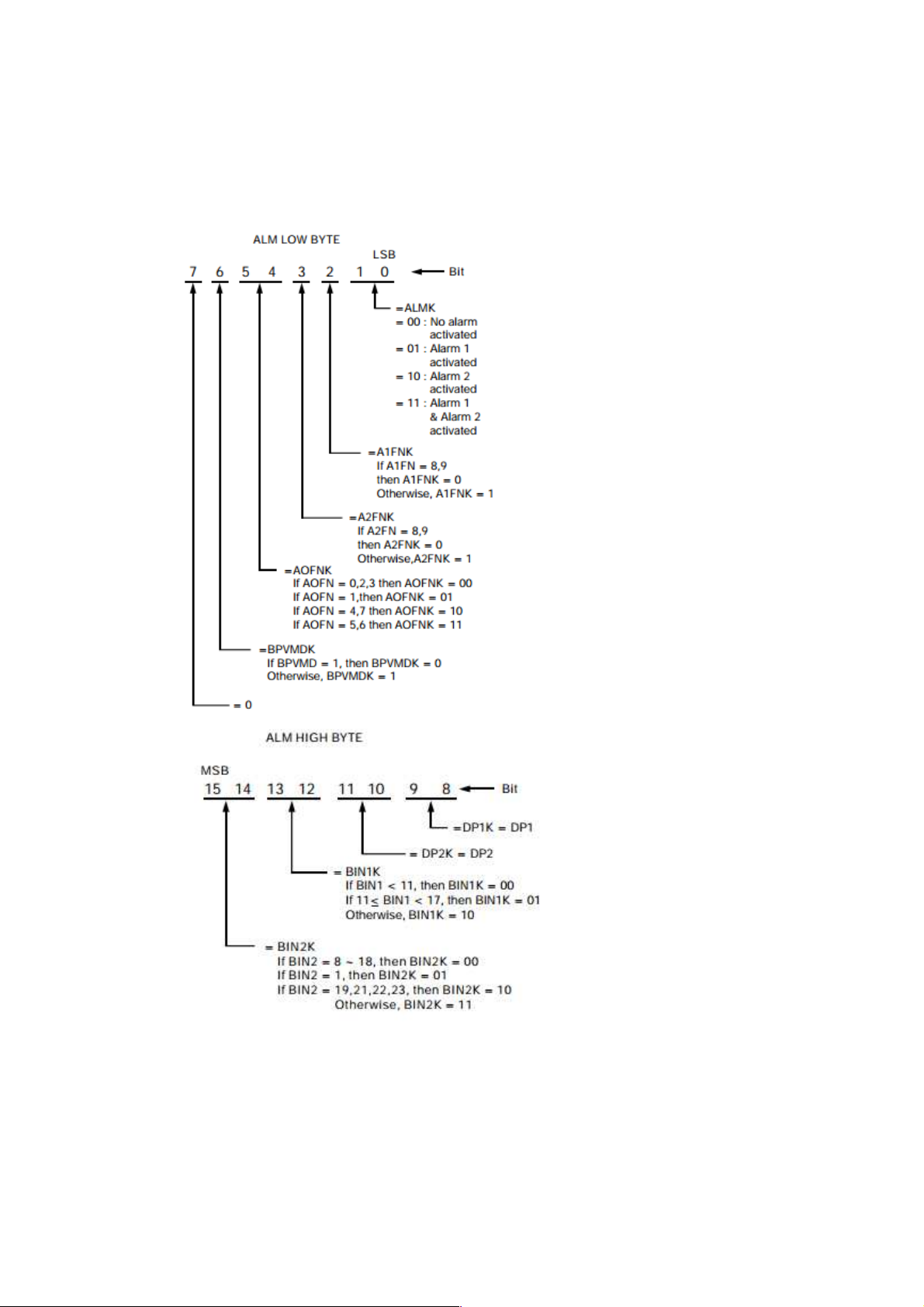
*B33: Description of Alarm Value
Page 62 of 113
Page 63

*B34: Error Messages
Error Code Display Symbol Error Description Corrective Action
1
2
3
Er 01
Illegal setup values
used: PV1 is used for
both PVMD and SPMD
that is meaningless for
control.
Er 02
Illegal setup values
used: PV2 is used for
both PVMD and SPMD
Check and correct setup
values of PVMD and
SPMD, PV and SV can't
use the same value for
normal control
Same as error code1
that is meaningless for
control
Illegal setup values
used: P1-2 or P2-1 is
used for PVMD while
Er 03
PV1 or PV2 is used for
SPMD. Dependent
values are used for PV
and SV will produce
incorrect result of
control
Check and correct setup
values of PVMD and
SPMD.
Difference of PV1 and
PV2 can't be used for
PV while PV1 or PV2
is used for SV
Check and correct setup
values of OUT2, PB1,
PB2, TI1, TI2 and OUT1.
IF OUT2 is required for
cooling control, the
control should use PID
mode
( PB = 0, TI = 0 ) and
OUT1 should use
reverse mode (heating
action), otherwise, don't
4
Illegal setup values
used: COOL is used for
Er 04
OUT2, but DIRT (cooling
action) is already used
for OUT1 or PID mode is
not
used for OUT1 (that is
PB1 or PB2 =0, and
TI1 or TI2 =0)
use OUT2 for cooling
control
Page 63 of 113
Page 64

Error Code Display Symbol Error Description Corrective Action
5
6
7
Illegal setup values
Er 05
used: unequal IN1U and
IN2U or unequal DP1
and DP2 while
P1-2 or P2-1 is used for
PVMD or, PV1 or PV2 is
used for SPMD or,
P1.2.H, P1.2.L, D1.2.H
or D1.2.L is used for
A1FN or A2FN.
Er 06
Illegal setup values
used: OUT2 select
=AL2 but A2FN select
Check and correct setup
values of IN1U
, IN2U, DP1, DP2,
PVMD, SPMD, A1FN or
A2FN. Same unit and
decimal point
should be used if both
PV1 and PV2 are used
for PV, SV, alarm1 or
alarm 2.
Check and correct setup
values of OUT2 and
A2FN. OUT2 will not
perform alarm function if
A2FN select NONE.
NONE
Er 07
Illegal setup values
used: Dwell timer (TIMR)
is selected for both
A1FN and A2FN.
Check and correct setup
values of A1FN and
A2FN. Dwell timer can
only be properly used for
single alarm output.
9 Er 09
Communication error:
receive error due to
parity error, framing
error, overrun error,
receive buffer full error,
frame check-sum error
or receive disturbed
1.Correct the
communication software
to meet the protocol
requirements
2. Add a terminating
resister to the multi- drop
link (RS-485) to
minimize the noise.
3. Use twisted pair wire
for RS-485 interface
connection to minimize
the noise.
4. Check the polarity of
RS-485 interface
connection.
Page 64 of 113
Page 65

Error Code Display Symbol Error Description Corrective Action
10 Er 10
11 Er 11
12 Er 12
14 Er 14
15 Er 15
Communication error:
bad function code
Communication error:
register address out of
range
Communication error:
access a non-existent
parameter
Communication error:
attempt to write a read
only data
Communication error:
write a value which is out
of range to a register
Correct the
communication software
to meet the protocol
requirements.
Don't issue an over-
range address of register
to the slave.
Don't issue a non-
existent parameter to
the slave.
Don't write a read only
data or a protected data
to the slave.
Don't write an over-
range data to the slave
register.
17 Er 17
18 Er 18
19 Er 19
20 Er 20
21 Er 21
Computing error: Illegal
(abnormal) floating point
data
Computing error:
Arithmetic result
overflow or underflow
Computing error:
divided by zero
Computing error: Illegal
BCD data entry
Timing error: A toD
conversion data error
due to overrun
Software bug. Return to
factory for repair.
Software bug. Return to
factory for repair.
Don't use an equal value
for AOLO and AOHI.
Software bug. Return to
factory for repair.
A to D converter doesn't
work properly. Return to
factory for repair.
Page 65 of 113
Page 66

Error Code Display Symbol Error Description Corrective Action
22 Er 22
23 Er 23
26 AtEr
Timing error: check-sum
error received during
multi-chip
communication
procedure
Timing error: wrong
function code received
during multi-chip
communication
procedure
Fail to perform
auto-tuning function
1. Correct the multi-chip
communication software
to meet the protocol
requirement.
2. Return to factory for
repair.
1. Correct the multi-chip
communication software
to meet the protocol
requirement.
2.Return to factory for
Repair.
1.The PID values
obtained after autotuning procedure are out
of range.Retry autotuning.
2.Don't change set point
value during auto-tuning
procedure.
3 .Don’t change Event
input state during autotuning procedure.
4.Use manual tuning
instead of auto-tuning.
27 CAER
Incorrect calibration
procedure or tolerance
of analog component too
big to meet specified
accuracy
1.Pay more attention to
the calibration
procedures.
2.Return to factory for
repair.
Page 66 of 113
Page 67

Error Code Display Symbol Error Description Corrective Action
t
sensor used is accordant
28 CAPE
29 EEPE
32 CJER
33 YYER
34 LLL2
Memory comparison
error, different value
detected in the
EEPROM and mapped
RAM
EEPROM can't be
written correctly
Cold junction
compensation device(s)
malfunction
Key switch shorted or
related PCB circuit
shorted
Input 2 ( IN2 ) signal too
low
1.Check and correct the
wiring and grounding
problems to minimize
the system noise.
2.Return to factory for
repair.
Return to factory for
repair.
Return to factory for
repair.
Return to factory for
repair.
1.Check if the input 2
sensor used is accordan
with IN2 type selection.
2.Check the connection
polarity of input 2
sensor.
3.Replace input 2
sensor.
35 HHH2
Input 2 ( IN2 ) signal too
high
1.Check if the input 2
with IN2 type selection.
2.Replace input 2
sensor.
Page 67 of 113
Page 68

Error Code Display Symbol Error Description Corrective Action
sensor used is accordant
nsor used is accordant
1.Check if the input 1
36 LLL1
37 HHH1
38 SB2E
Input 1 ( IN1 ) signal too
low
Input 1 ( IN1 ) signal too
high
Input 2 ( IN2 ) sensor
break, or input 2 current
below 1 mA if
4-20 mA is selected, or
input2 voltage below
0.25V if 1 - 5V is
selected
with IN1 type selection.
2.Check the connection
polarity of input 1
sensor.
3.Replace input 1
sensor.
1.Check if the input 1
se
with IN1 type selection.
2.Replace input 1
sensor.
Replace input 2 sensor.
39 SB1E
40 ADER
Table 4-34.Error Codes and Corrective Actions
Input 1 ( IN1 ) sensor
break, or input 1 current
below 1 mA if
4-20 mA is selected, or
input1 voltage below
0.25V if 1 - 5V is
selected
A to D converter or
related component(s)
malfunction
Replace input 1 sensor.
Return to factory for
repair.
Page 68 of 113
Page 69
*B35:PROG CODE Description
Parameter
Value
0.XX BTC-2500 controller
1.XX BTC-4300 controller
2.XX BTC-9500 controller
3.XX BTC-8300 controller
4.XX BTC-4300 controller & Process Control card
of PR
5.XX BTC-7200 controller
6.XX BTC-9100 controller
7.XX SM-40A smart panel meter
8.XX Reserved
9.XX ST-30A smart transmitter
Specified product
10.XX Reserved
11.XX Reserved
12.XX Reserved
13.XX Reserved
14.XX ST-20A smart transmitter ( software setup)
15.XX ST-20A smart transmitter ( DIP switches
setup )
Table 4-35 PROG CODE
Page 69 of 113
Page 70
*B36: Display Symbol and Description of MODE
Parameter Value Description
X.0 Perform normal mode
X.1 Enter calibration mode
X.2 Enter auto-tuning mode
X.3 Enter failure mode
X.4 Enter manual mode
X.5 Enter sleep mode
0.X Unlock condition
1.X SP1, SEL1 SEL5 are unlocked
2.X Lock all parameters except SP1
3.X All parameters are locked
Table 4-36 Mode
*C: The Parameters are preset with the default values specified in the table during production
*E: The unit PV means that the unit of parameter is the same as the unit of PV (process value ).The unit
of PV is determined by PVMD , IN1, IN2, IN1U, and IN2U.
*E1: Unit determination for A1SP, A1DV and A1HY
If A1FN= Range of A1SP same as range of
DE.HI,DE.LO,DB.HI,DB.LO PV
PV1.H,PV1.L PV1
PV2.H,PV.L PV2
P1.2.H,P1.2.L,D1.2.H,D1.2.L PV1,PV2
Table 4-37.Unit Determination for A1SP,A1DV,A1HY
Page 70 of 113
Page 71
*E2: Unit determination for A2SP, A2DV and A2HY
If A2FN= Range of A2SP same as range of
DE.HI,DE.LO,DB.HI,DB.LO PV
PV1.H,PV1.L PV1
PV2.H,PV.L PV2
P1.2.H,P1.2.L,D1.2.H,D1.2.L PV1,PV2
Table 4-38.Unit Determination for A2SP,A2DV,A2HY
*E3: Unit determination for Ramp
If SPMD= Unit
MIN.R PV/Minute
HR.R PV/Hour
Table 4-39.RAMP Unit
*E4: Unit determination for AOLO and AOHI
If AOFN= Same Unit as Unit of
PV1 PV1
PV2 PV2
P1-2,P2-1 PV1,PV2
SV PV
MV1,MV2 %
Table 4-40 .Unit Determination of AOLO & AOHI
*E5: Unit is the same as unit of PV1 ( IN1 )
*E6: Unit is the same as unit of PV2 ( IN2 )
Page 71 of 113
Page 72
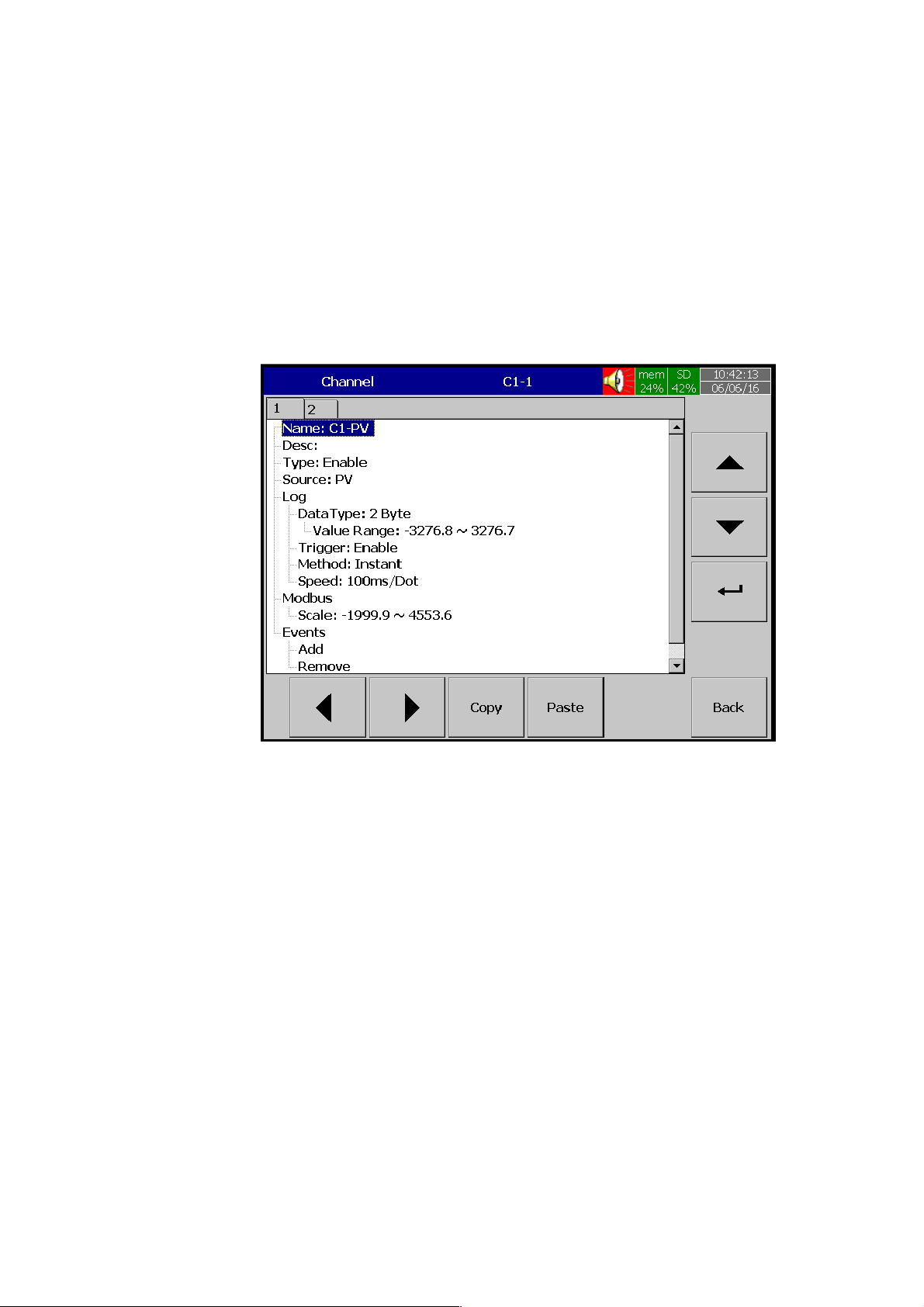
4.3.1.1.3 Channel
The Channel will allow the user to configure the logging parameters. Press Channel and
then press Enter Soft key to access the Channel parameter of Process Control Card.
Figure 4-24.Process Control Card Channel Configuration
Name:
Enable the user to define the name for each channel with the maximum limit of 18
Characters. Select “Name”, then Press “Enter”, soft key, a keyboard with several keys
appears. Press “Shift” to select special characters. Press “Caps” to select capital letters.
Press soft key “OK” after entering a new channel name.
Desc:
The description about a specific channel on the display.
Type:
Option available to enable or disable the channel from logging.
Page 72 of 113
Page 73

Source:
There are two options are available for source. They are as below
PV
SV
The first channel will show PV and the second Channel will show SV in source. These
two parameters can be logged in the recorder from the Process Control Card.
By using the Key to switch between Channels.
Log:
This is to set the desired logging parameter settings
Data Type:
2 byte
2 byte range: -3276.8 to +3276.7
Trigger:
Two options are available
Disable: Select disable while the recording of a specific channel is not required.
Enable: Select Enable while the recording of a specific channel is required.
Method:
This is the method of logging measured data. Select Method and Press “Enter”,
soft key to have the selection of different log methods. Then choose the required Log
method. The available log methods are as below.
Instant: logging the last measured data at the sampling interval
Average: logging the averaged measured data at the sampling interval
Minimum: logging the minimum measured data at the sampling interval
Maximum: logging the maximum measured data at the sampling interval
Speed:
It is the logging speed (recording speed) of measured data. Select Log Speed and
then choose log speed to one of the below.
Page 73 of 113
Page 74
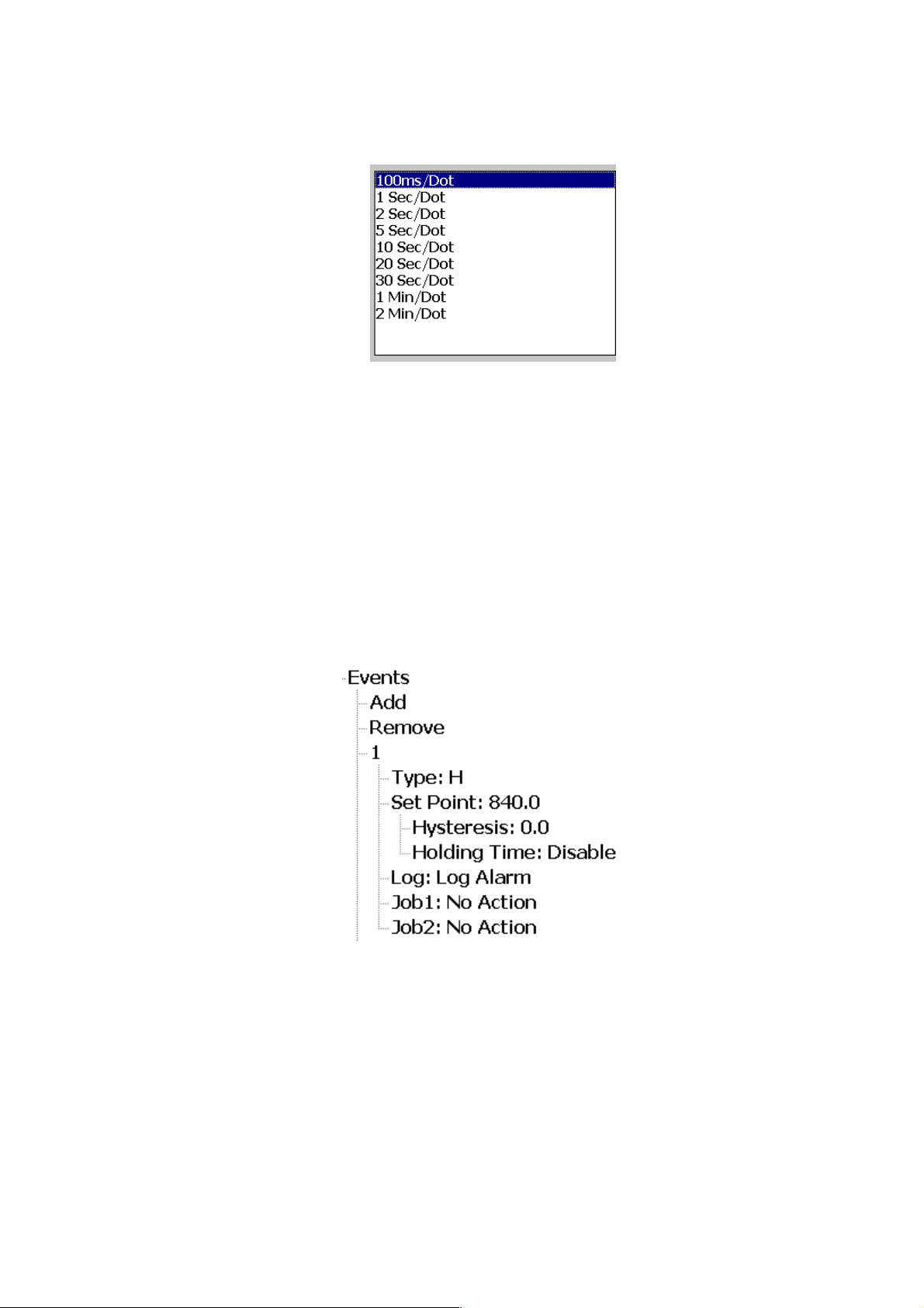
Figure 4-25.Log Speed
Modbus Scale:
Scale for reading the Analog Input Values through Modbus
Events
Events are generally used to generate Alarms. The Events can also be used to process
Digital Output, Timer, Counter, Totalizers and to generate report.
There are maximum 5 Events can be added for Analog Inputs.
Press Add to Add the Events. Press Remove to Remove the Events.
Figure 4-26.Events with Job
Type:
There are different types are available to select for Job of Event or Alarm. The available
types are H, L, HH, LL, Dev+, Dev-, and Error
H: High limit. When the process is over high limit, the alarm or job is actuated.
Page 74 of 113
Page 75

L: Low limit. Any the process is lower than low limit, the alarm or job is actuated.
HH: High High limit, to set up another limit higher than high limit for double warning.
LL: Low Low limit, to set up another limit lower than low limit for double warning.
Dev+: Trigger an event on positive deviation of process value. The job or alarm is activated when
process value is deviated more than the set point in positive direction. (Set point +Previous
sampled Process Value)
Example:
Set point =10
At 10.00.01 Hrs Tag1=40
At 10.00.02 Hrs Tag1 = 51
Then, job or alarm is activated
Dev-: Trigger an event on negative deviation of process value. The job or alarm is activated when
process value is deviated less than the set point in negative direction. (Previous sampled Process
Value-Set point)
Example:
Set point =10
At 10.00.01 Hrs, Tag1=40
At 10.00.02 Hrs, Tag1 = 29
Then, job or alarm is activated.
Error: On Channel error, an alarm or job is activated
Set point: To set up the process value for actuating Job1 and /or Job2
Alarm
Log Alarm: Record alarms
Log Alarm (Auto Ack): Record alarms and acknowledge automatically
Log Event: Record events
Job1, Job2:
When an event occurs, the task to be performed is called the job. A typical example is to
trigger an alarm buzzer in the event of a high temperature. Each Channel can accept five different
types of events (or alarms) and each event can create two jobs. Please note that a job under Event
is different from a job created by pressing the Operate key. The former is actuated by an event,
and the latter is actuated by manual control, no event necessary.
Note: Please refer to the section “Jobs”in Recorder user manual for full details about
various jobs available
Page 75 of 113
Page 76
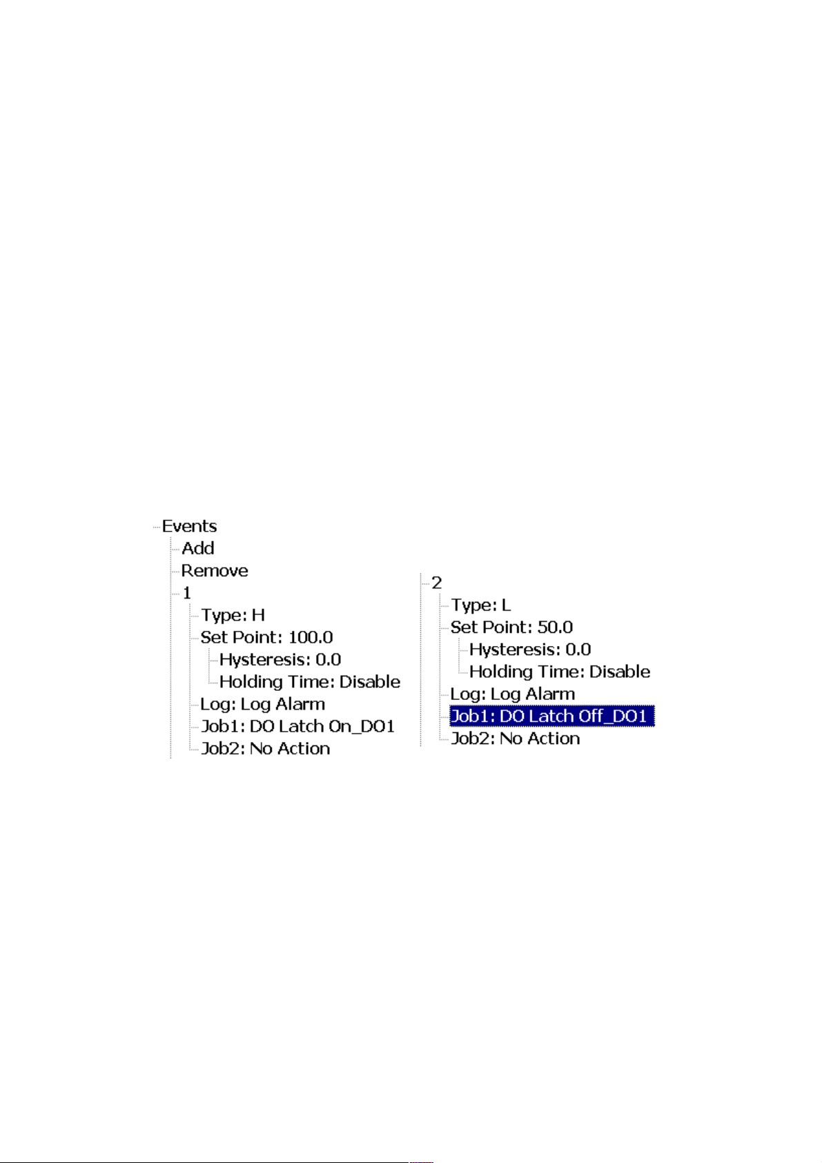
Hysteresis
To avoid the event or alarm has been activated too often hysteresis value can be set for
the alarm to change it in to normal state. Hysteresis value can be defined for the event trigger set
point.
Holding time:
It refers to, suppose the set point is reached, but the user want to wait for some time to
activate that action. This time is holding time. In process sometimes SP is reached but it will go
down immediately, that might due to process instability. To encounter this issue the user have
given an holding time, to see that PV stays at above that SP more than the holding time and then
activate action for that event.
Example1
If the temperature is increased to more than 100 °C, log alarm and switch on digital
output1. When the temperature is decreased to less than 50 °C, log the alarm and switch off the
digital output1. Setting of events for the analog input in the channel configuration is as follows.
Figure 4-27. Event Configuration Example
4.3.1.1.4 Sample Configuration of Process Control Card
4.3.1.1.4.1 Heat Only ON-OFF Control
Select REVR for OUT1, Set PB1 to 0, SP1 is used to adjust set point value, O1HY is used
to adjust dead band for ON-OFF control, TIME is used to adjust the dwell timer (enabled by
Page 76 of 113
Page 77
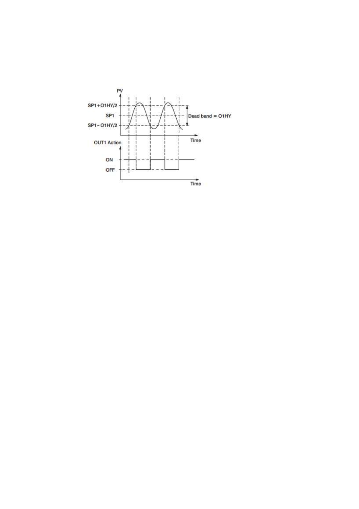
selecting TIMR for A1FN or A2FN). The output 1 hysteresis (O1HY) is enabled in case of PB1
= 0. The heat only on-off control function is shown in the following diagram.
Figure 4-28.Heat Only ON-OFF Control
The ON-OFF control may introduce excessive process oscillation even if Hysteresis is
minimized to the smallest. If ON-OFF control is set (i.e. PB1 = 0), TI1, TD1, CYC1, OFST, CPB
and PL1 will be hidden and have no function to the system. The manual mode, auto-tuning, selftuning and bumpless transfer will be disabled too.
Select REVR for OUT1, set TI1 to 0, SP1 is used to adjust set point value, TIME is used to
adjust the dwell timer (enabled by selecting TIMR for A1FN or A2FN). OFST been enabled in case
of TI1 = 0 is used to adjust the control offset ( manual reset ). Adjust CYC1 according to
The output 1 type ( O1TY ).Generally, CYC1= 0.5 ~ 2 sec for SSRD and SSR, CYC1=10 ~ 20 sec
for relay output .CYC1 is ignored if linear output is selected for O1TY. If PB1 is not equal to 0.
OFST is measured by % with range 0 - 100.0 %. In the steady state ( i.e. process has been
stabilized ) if the process value is lower than the set point a definite value, say 5 C, while 20 C is
used for PB1, that is lower 25 %, then increase OFST 25 %, and vice versa. After adjusting OFST
value, the process value will be varied and eventually, coincide with set point.
Using the P control ( TI1 set to 0 ), the auto-tuning and self-tuning are disabled. Manual
reset ( adjust OFST ) is not practical because the load may change from time to time and often
need to adjust OFST repeatedly. The PID control can avoid this situation. Selecting REVR for
OUT1, SP1 is used to adjust set point value.
TIME is used to adjust the dwell timer ( enabled by selecting TIMR for A1FN or A2FN ).
PB1 and TI1 should not be zero. Adjust CYC1 according to the output 1 type ( O1TY ). Generally,
CYC1 = 0.5 ~ 2 sec for SSRD and SSR, CYC1 = 10 ~ 20 sec for relay output. CYC1 is ignored if
linear output is selected for O1TY.
In most cases the self-tuning can be used to substitute the auto-tuning. See If self-tuning
is not used ( select NONE for SELF ), then use auto-tuning for the new process, or set PB1, TI1
and TD1 with historical values. If the control result is still unsatisfactory, then use manual tuning to
Page 77 of 113
Page 78
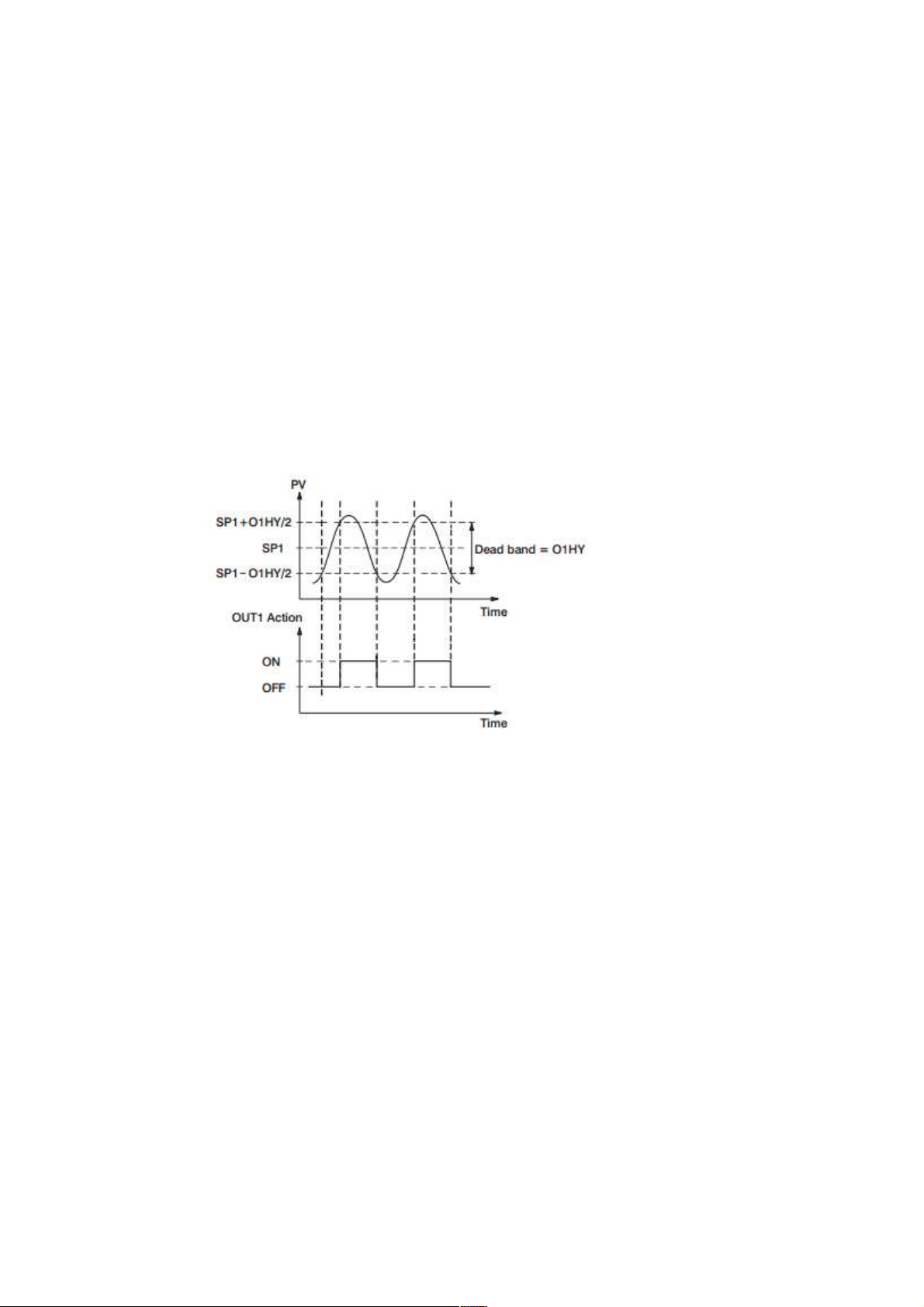
improve the control .This Process Control Card contains a very clever PID and Fuzzy algorithm to
achieve a very small overshoot and very quick response to the process if it is properly tuned.
4.3.1.1.4.2 Cool Only ON-OFF Control
ON-OFF control, P (PD) control and PID control can be used for cool control. Set OUT1 to
DIRT (direct action). The other functions for cool only ON-OFF control, cool only P(PD) control
and cool only PID control are same as Heat only ON-OFF Control except that the output variable
(and action ) for the cool control is inverse to the heat control, such as the following diagram
shows:
4.3.1.1.4.3 Heat Cool Control
The Heat-Cool Control can use one of 6 combinations of control modes. Setups of
Parameters for each control mode are shown in the following table.
Figure 4-29.Cool Only ON-OFF Control
Page 78 of 113
Page 79
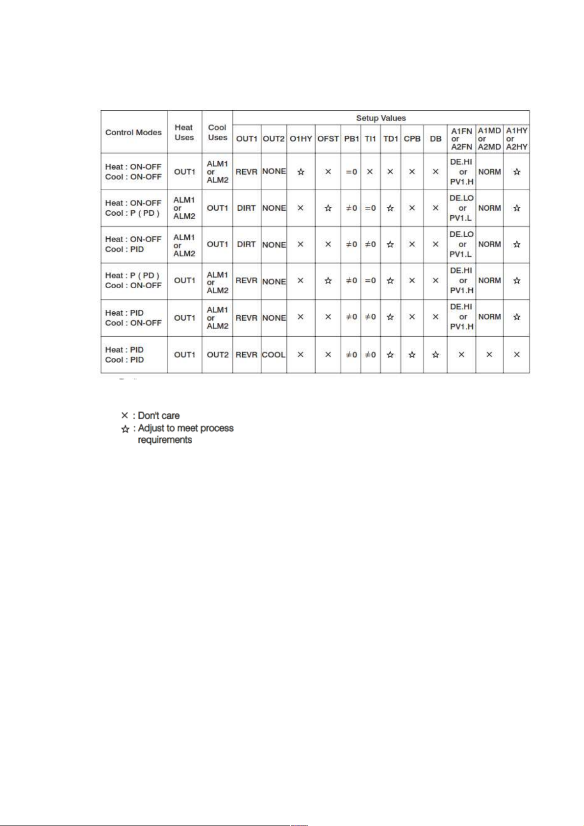
Table 4-41.Heat Cool Control Modes
Note
The ON-OFF control may result excessive overshoot and undershoot problems in the
process. The P (or PD) control will result in a deviation process value from the set point. It is
recommended to use PID control for the Heat-Cool control to produce a stable and zero offset
process value.
Other Setup Required
O1TY, CYC1, O2TY, CYC2, A2SP, A2DV,O1TY & O2TY are set in accordance with the
types of OUT1 & OUT2 installed. CYC1 & CYC2 are selected according to the output 1 type
( O1TY ) & output 2 type ( O2TY ).Generally, selects 0.5 ~ 2 sec. for CYC1, if SSRD or SSR is
used for O1TY; 10 ~ 20 sec. if relay is used for O1TY, and CYC1 is ignored if linear output is used.
Similar condition is applied for CYC2 selection.
Examples
Heat PID+Cool ON-OFF: Set OUT1= REVR, A1FN or A2FN= PV1.H, A1FN or
A2MD=NORM, A1HY or A2HY=0.1, PB1=0, TI1=0, TD1=0, and set appropriate
values for O1TY and CYC1.
Page 79 of 113
Page 80
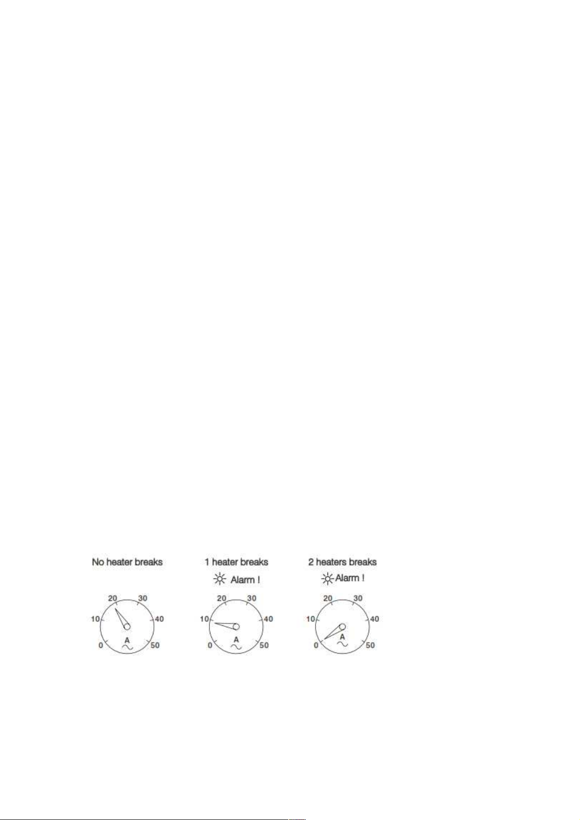
Heat PID+Cool PID: set OUT1=REVR, OUT2=COOL, CPB=100, DB=-4.0, PB1=0,
TI1=0, TD1=0, and set appropriate values for O1TY, CYC1, O2TY, and CYC2.
CPB Programming
The cooling proportional band is measured by % of PB with range 1~255. Initially set
100% for CPB and examine the cooling effect. If cooling action should be enhanced then decrease
CPB .If cooling action is too strong then increase CPB. The value of CPB is related to PB and its
value remains unchanged throughout the self-tuning and auto-tuning procedures.
Adjustment of CPB is related to the cooling media used. For air is used as cooling media,
adjust CPB at 100(%). For oil is used as cooling media, adjust CPB at 125(%). For water is used as
cooling media, adjust CPB at 250(%)
DB Programming
Adjustment of DB is dependent on the system requirements. If more positive value of DB
(greater dead band) is used, an unwanted cooling action can be avoided but an excessive
overshoot over the set point will occur. If more negative value of DB (greater overlap) is used, an
excessive overshoot over the set point can be minimized but an unwanted cooling action will occur.
It is adjustable in the range -36.0% to 36.0 % of PB1 (or PB2 if PB2 is selected). A negative DB
value shows an overlap area over which both outputs are active. A positive DB value shows a dead
band area over which neither output is active
4.3.1.1.4.4 Heater Break Alarm
A current transformer CT94-1 should be installed to detect the heater current if a heater
break alarm is required. The CT signal is sent to input 2, and the PV2 will indicate the heater
current in 0.1 Amp. Resolution. The range of current transformer is 0 to 50.0 Amps.
Example
A furnace uses two 2KW heaters connected in parallel to warm up the process. The line
voltage is 220V and the rating current for each heater is 9.09A. If we want to detect any one
heater break, set A1SP=13.0A, A1HY=0.1 A1FN=PV2.L, A1MD=NORM, then
Figure 4-30. Heater Break Alarm
Page 80 of 113
Page 81

4.3.1.1.4.5 Loop Break Alarm
A1FN selects LB if alarm 1 is required to act as a loop break alarm. Similarly, if alarm 2 is
required to act as a loop break alarm, then set OUT2 with=AL2 and A1FN with LB.
TIME, A1SP, A1DV and A1HY are hidden if alarm 1 is configured as a loop break alarm.
Similarly, TIME, A2SP, A2DV and A2HY are hidden if alarm 2 is configured as a loop break alarm.
One of 4 kinds of alarm modes can be selected for alarm 1 and alarm 2.
These are: Normal alarm, latching alarm, Holding alarm and Latching/Holding alarm. However, the
Holding mode and latching/Holding mode are not recommended to be chosen for loop break alarm
since loop break alarm will not perform holding function even if it is set with holding or
latching/holding mode.
Loop Break Conditions are detected during a time interval of 2TI1 (double of integral time,
but 120 seconds maximum). Hence the loop break alarm doesn't respond quickly as it occurs. If
the process value doesn't increase (or decrease) while the control variable MV1 has reached to its
maximum (or minimum) value within the detecting time interval, a loop break alarm (if configured)
will be actuated.
Loop Break Alarm (if configured) occurs when any following condition happens
Input sensor is disconnected (or broken).
Input sensor is shorted.
Input sensor is defective.
Input sensor is installed outside (isolated from) the process.
Controller fails (A-D converter damaged).
Heater ( or generally, chiller, valve, pump, motor etc. ) breaks or fails or uninstalled
Switching device (used to drive heater) is open or shorted.
4.3.1.1.4.6 Sensor Break Alarm
Alarm 1 or alarm 2 can be configured as sensor break alarm by selecting SENB for A1FN
or A2FN.The sensor break alarm is activated as soon as failure mode occurs. Note that A-D failure
also creates a sensor break alarm. TIME, A1SP, A1DV, and A1HY are hidden if alarm 1 is
configured as a sensor break alarm. Similarly, TIME, A2SP, A2DV and A2HY are hidden if alarm 2
is configured as a sensor break alarm.
One of 4 kinds of alarm modes can be selected for sensor break alarm. These are: Normal
alarm, latching alarm, Holding alarm and Latching/Holding alarm. However, the Holding alarm and
Latching/Holding alarm are not recommended to be chosen for sensor break alarm since sensor
break alarm will not perform holding function even if it is set with holding or latching/holding mode.
Page 81 of 113
Page 82

4.3.1.1.4.7 Failure Transfer
The controller will enter failure mode as one of the following conditions occurs.
SB1E Error occurs ( due to the input 1 sensor break or input 1 current below
1mA,if 4-20 mA is selected or input 1 voltage below 0.25V if 1-5 V is selected ), if
PV1, P1-2 or P2-1 is selected for PVMD or PV1 is selected for SPMD.
SB2E Error occurs ( due to the input 2 sensor break or input 2 current below
1mA,if 4-20 mA is selected or input 2 voltage below 0.25V if 1-5 V is selected ), if
PV2, P1-2 or P2-1 is selected for PVMD or PV2 is selected for SPMD.
ADER Error occurs due to the A-D converter of the controller fails.
The output 1 and output 2 will perform the function as one of the following conditions occurs.
During power starts (within 2.5 seconds).
The controller enters the failure mode.
The controller enters the manual mode.
The controller enters the calibration mode.
Output 1 Failure Transfer, if activated, will perform
If output 1 is configured as proportional control (PB1≠0), and BPLS selected for
O1FT, then output 1 will perform bumpless transfer. Thereafter the previous
averaging value of MV1 will be used for controlling output 1.
If output 1 is configured as proportional control (PB1 ≠ 0), and a value of 0 to
100.0 % is set for O1FT, then output 1 will perform failure transfer. Thereafter the
value of O1FT will be used for controlling output 1.
If output 1 is configured as ON-OFF control (PB1 = 0), then output 1 will be driven
OFF if O1FN selects REVR and be driven ON if O1FN selects DIRT.
If output 1 is configured as ON-OFF control (PB1=0), then output 1 will be driven
OFF if O1FN selects REVR and be driven ON if O1FN selects DIRT.
Output 2 Failure Transfer, if activated, will perform
If OUT2 selects COOL, and BPLS is selected for O1FT, then output 2 will perform
bumpless transfer. Thereafter the previous averaging value of MV2 will be used for
controlling output 2.
If OUT2 selects COOL, and a value of 0 to 100.0 % is set for O2FT, then output 2
will perform failure transfer. Thereafter the value of O1FT will be used for
controlling output 2.
Alarm 1 Failure Transfer is activated as the controller enters failure mode. Thereafter the
alarm 1 will transfer to the ON or OFF state preset by A1FT.
Exception: If Loop Break (LB) alarm or sensor Break (SENB) alarm is configured for
A1FN, the alarm 1 will be switched to ON state independent of the setting of A1FT. If Dwell Timer
(TIMR) is configured for A1FN, the alarm 1 will not perform failure transfer.
Page 82 of 113
Page 83
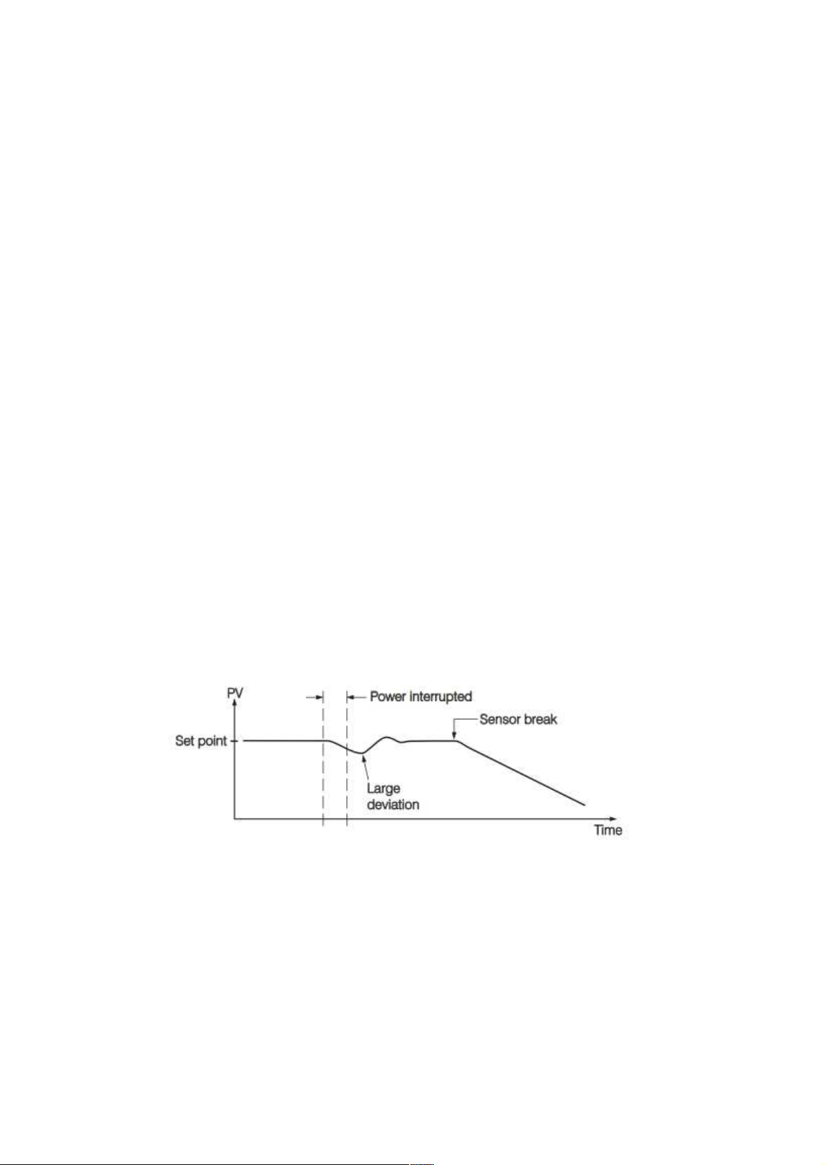
Alarm 2 Failure Transfer is activated as the controller enters failure mode. Thereafter the
alarm 2 will transfer to the ON or OFF state preset by A2FT.Alarm 2 Failure Transfer is activated
as the controller enters failure mode.
Exception: If Loop Break (LB) alarm or sensor Break (SENB) alarm is configured for
A2FN, the alarm 2 will be switched to ON state independent of the setting of A2FT. If Dwell Timer
(TIMR) is configured for A2FN, the alarm 2 will not perform failure transfer.
4.3.1.1.4.8 Bumpless Transfer
The bumpless transfer function is available for output 1 and output 2 (provided that OUT2
is configured as COOL).
Bumpless Transfer is enabled by selecting BPLS for O1FT and/or O2FT and activated as one
of the following cases occurs.
Power starts (within 2.5 seconds).
The controller enters the failure mode.
The controller enters the manual mode.
The controller enters the calibration mode.
As the bumpless transfer is activated, the controller will transfer to open-loop control and
uses the previous averaging value of MV1 and MV2 to continue control.
Without Bumpless Transfer
Since the hardware and software need time to be initialized, the control is abnormal as the
power is recovered and results in a large disturbance to the process. During the sensor breaks, the
process loses power.
Figure 4-31.Without Bumpless Transfer
Without Bumpless Transfer
After bumpless transfer is configured with the correct control variables applied, the
disturbance is small when the power is recovered. During the sensor breaks, the controller
Page 83 of 113
Page 84
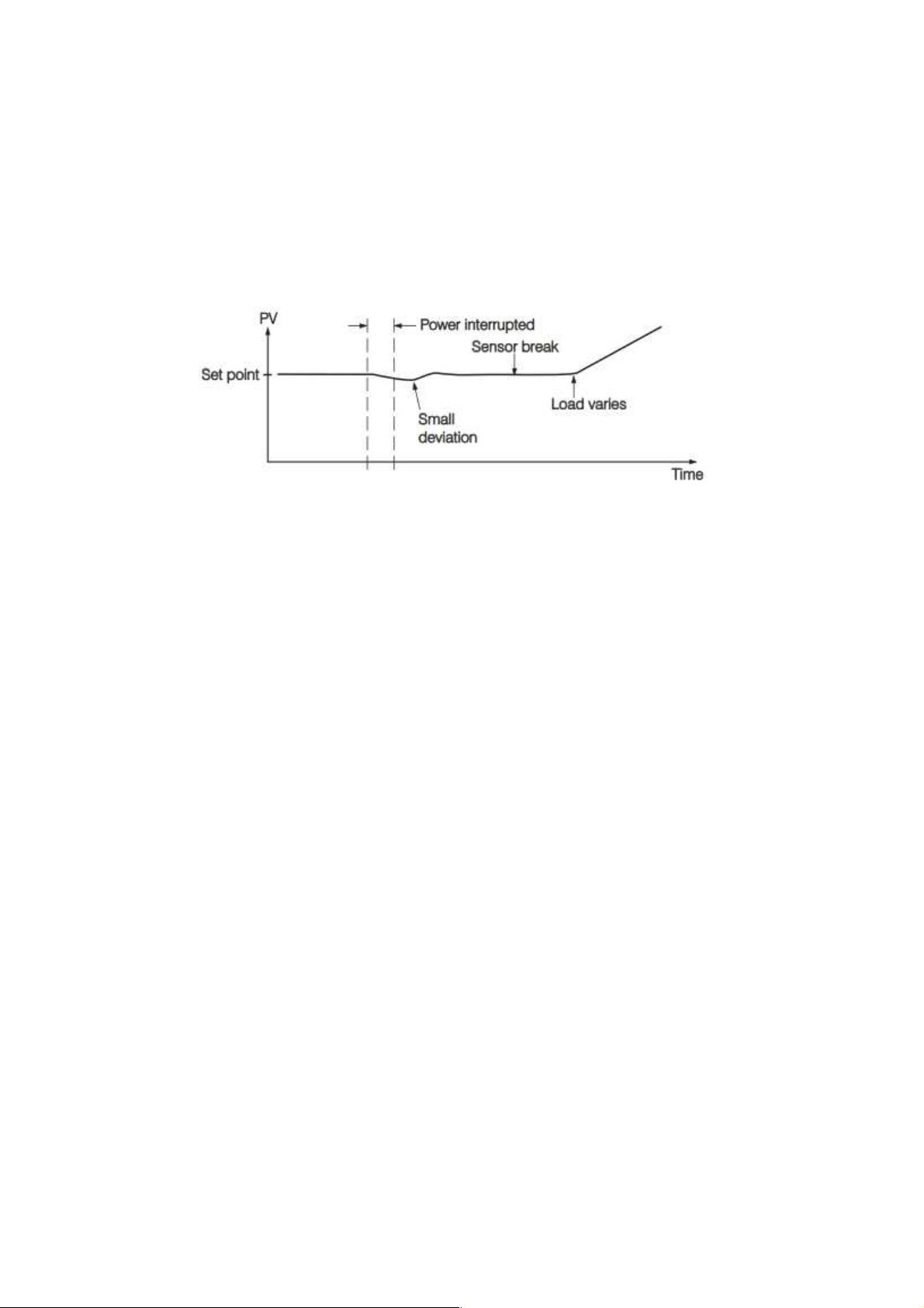
continues to control by using its previous value. If the load doesn't change, the process will remain
stable. Thereafter, once the load changes, the process may run away. Therefore, the user should
not rely on a bumpless transfer for a longer time. For fail safe reason, an additional alarm should
be used to announce the operator when the system fails. For ,a Sensor Break Alarm, if configured,
will switch to failure state and announces the operator to use manual control or take a proper
security action when the system enters failure mode.
Figure 4-32.With Bumpless Transfer
Warning: After system fails, never depend on bumpless transfer for a long time; otherwise
it might cause a problem to the system to run away.
4.3.1.1.4.9 PV1 Shift
In certain applications it is desirable to shift the controller display value from its actual
value. This can be easily accomplished by using the PV1 shift function. Press the “scroll " key to
the parameter SHIF in card parameter. The value you adjust here, either positive or negative, will
be added to the actual value. The SHIF function will alter PV1 only.
Here is an example. A process is equipped with a heater, a sensor and a subject to be
warmed up. Due to the design and position of the components in the system, the sensor could not
be placed any closer to the part. Thermal gradient (different temperature) is common and
necessary to an extent in any thermal system for heat to be transferred from one point to another.
If the difference between the sensor and the subject is 35 C, and the desired temperature at the
subject to be heated is 200 C, the controlling value or the temperature at the sensor should be 235
C. You should input -35 C as to subtract 35 C from the actual process display. This in turn will
cause the controller to energize the load and bring the process display up to the set point value
Page 84 of 113
Page 85
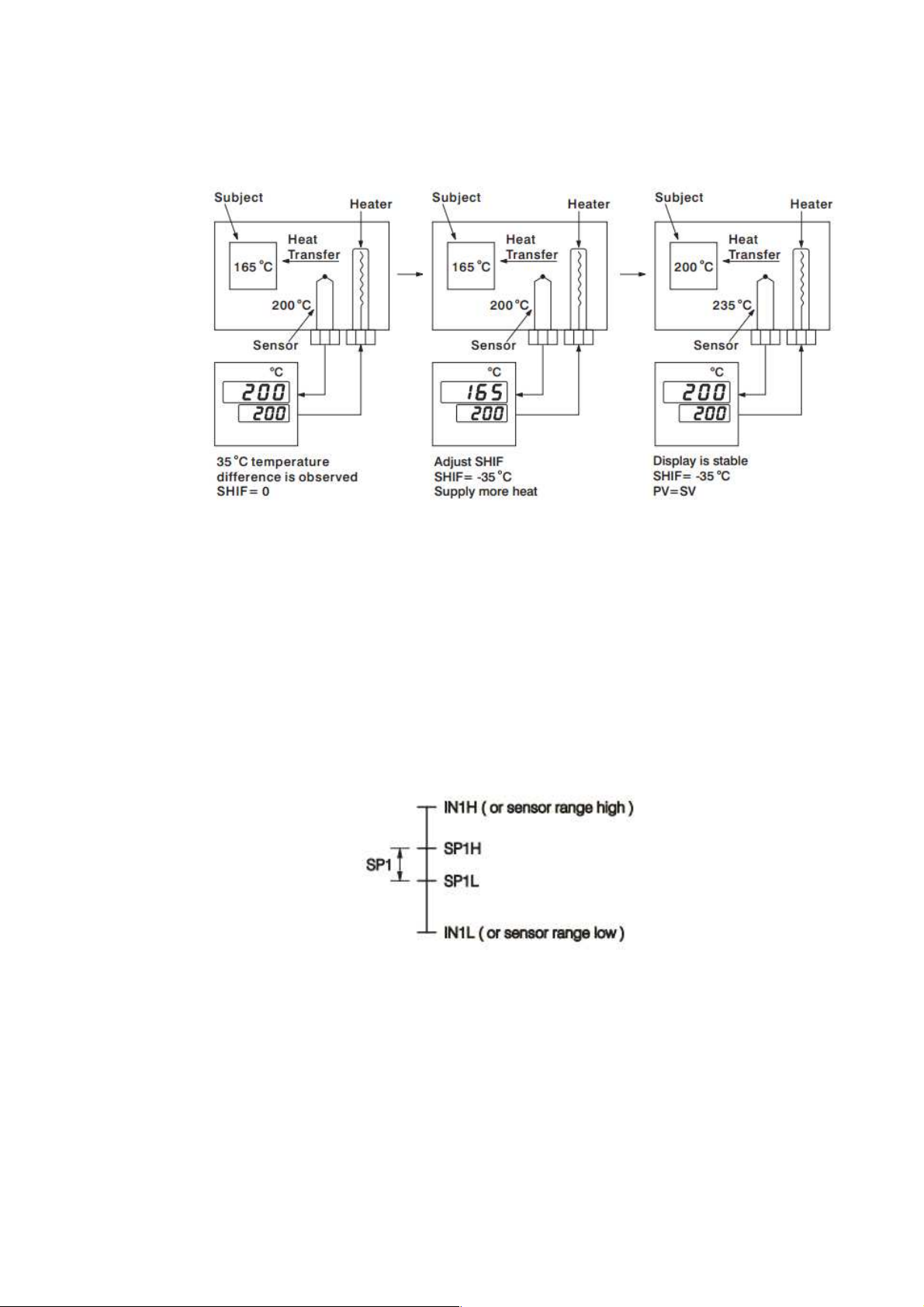
4.3.1.1.4.10 SP1 Range
SP1L (SP1 low limit value) and SP1H (SP1 high limit value) in setup menu are used to
confine the adjustment range of SP1.
Example: A freezer is working in its normal temperature range -10 C to -15 C. In order to
avoid an abnormal set point, SP1L and SP1H are set with the following values:
SP1L = -15 C SP1H = -10 C
Now SP1 can only be adjusted within the range from -10 C to -15 C.
Figure 4-33.PV1 SHIFT Application
4.3.1.1.4.11 Dwell Timer
Alarm 1 or alarm 2 can be configured as dwell timer by selecting TIMR for A1FN or A2FN,
but not both, otherwise Error will appear. As the dwell timer is configured, the parameter TIME is
used for dwell time adjustment. The dwell time is measured in minute ranging from 0 to 6553.5
minutes. Once the process reaches the set point the dwell timer starts to count from zero until time
Figure 4-34.SP1 Range
Page 85 of 113
Page 86
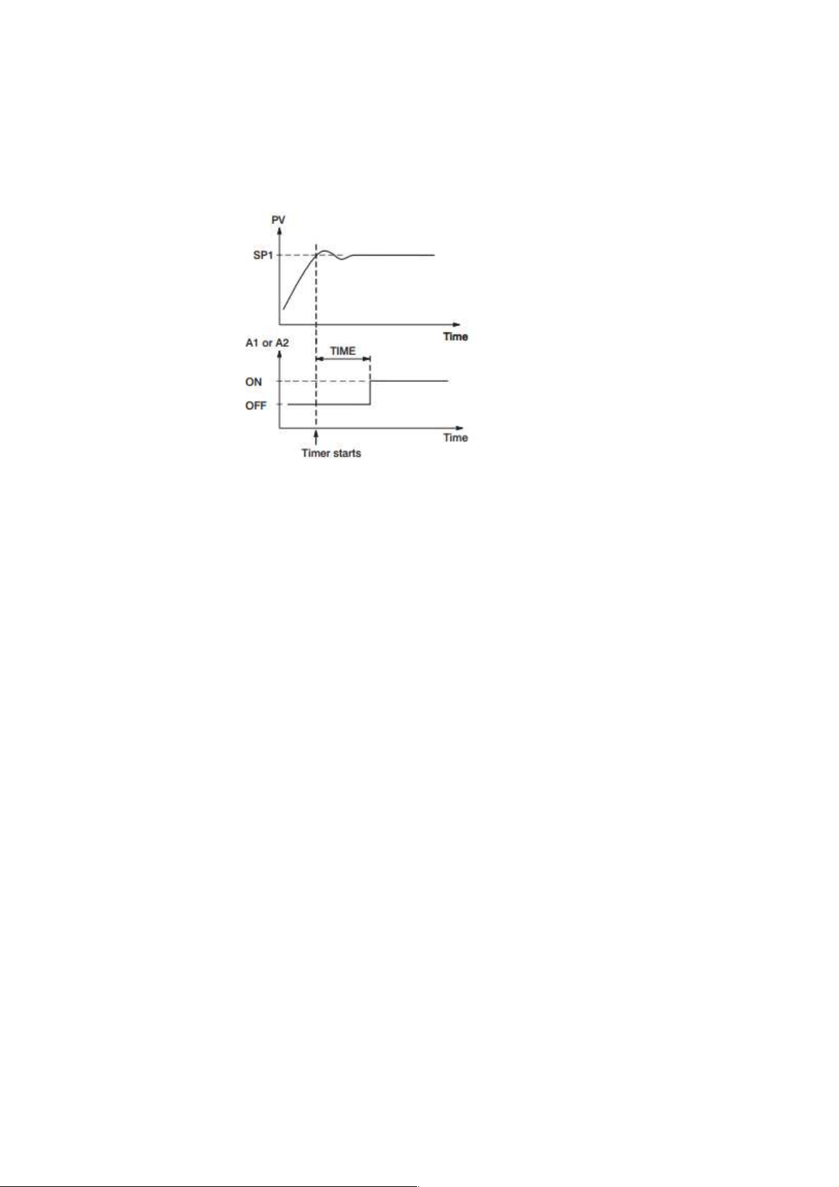
out. The timer relay will remain unchanged until time out. The dwell timer operation is shown as
following diagram.
Figure 4-35.Dwell Timer
If alarm 1 is configured as dwell timer, A1SP, A1DV, A1HY and A1MD are hidden. Same
case is for alarm 2.
Example
Set A1FN=TIMR or A2FN=TIMR but not both. Adjust TIME in minutes .A1MD (if
A1FN=TIMR) or A2MD (if A2FN=TIMR) is ignored in this case.
4.3.1.1.4.12 Process Alarms
A process alarm sets an absolute trigger level (or temperature). When the process (could
be PV1, PV 2 or PV1-PV2) exceeds that absolute trigger level an alarm occurs. A process alarm is
independent from set point. Adjust A1FN (Alarm 1 function) in setup menu. One of 8 functions can
be selected for process alarm. These are: PV1.H, PV1.L, PV2.H, PV2.L, P1.2.H,
P1.2.L, D1.2.H, D1.2.L.
When the PV1.H or PV1.L is selected the alarm examines the PV1 value. When the
PV2.H or PV2.L is selected the alarm examines the PV2 value.
When the P1.2.H or P1.2.L is selected the alarm occurs if the PV1 or PV2 value
exceed the trigger level. When the D1.2.H or D1.2.L is selected the alarm occurs if the PV1-PV2
(difference) value exceeds the trigger level. The trigger level is determined by A1SP (Alarm 1 set
point) and A1HY (Alarm 1 hysteresis value) in configuration for alarm 1. The hysteresis value is
introduced to avoid interference action of alarm in a noisy environment. Normally A1HY can be set
with a minimum (0.1) value. A1DV and/or A2DV are hidden if alarm 1 and/or alarm 2 are set with
process alarm.
Normal Alarm: A1MD = NORM
Page 86 of 113
Page 87
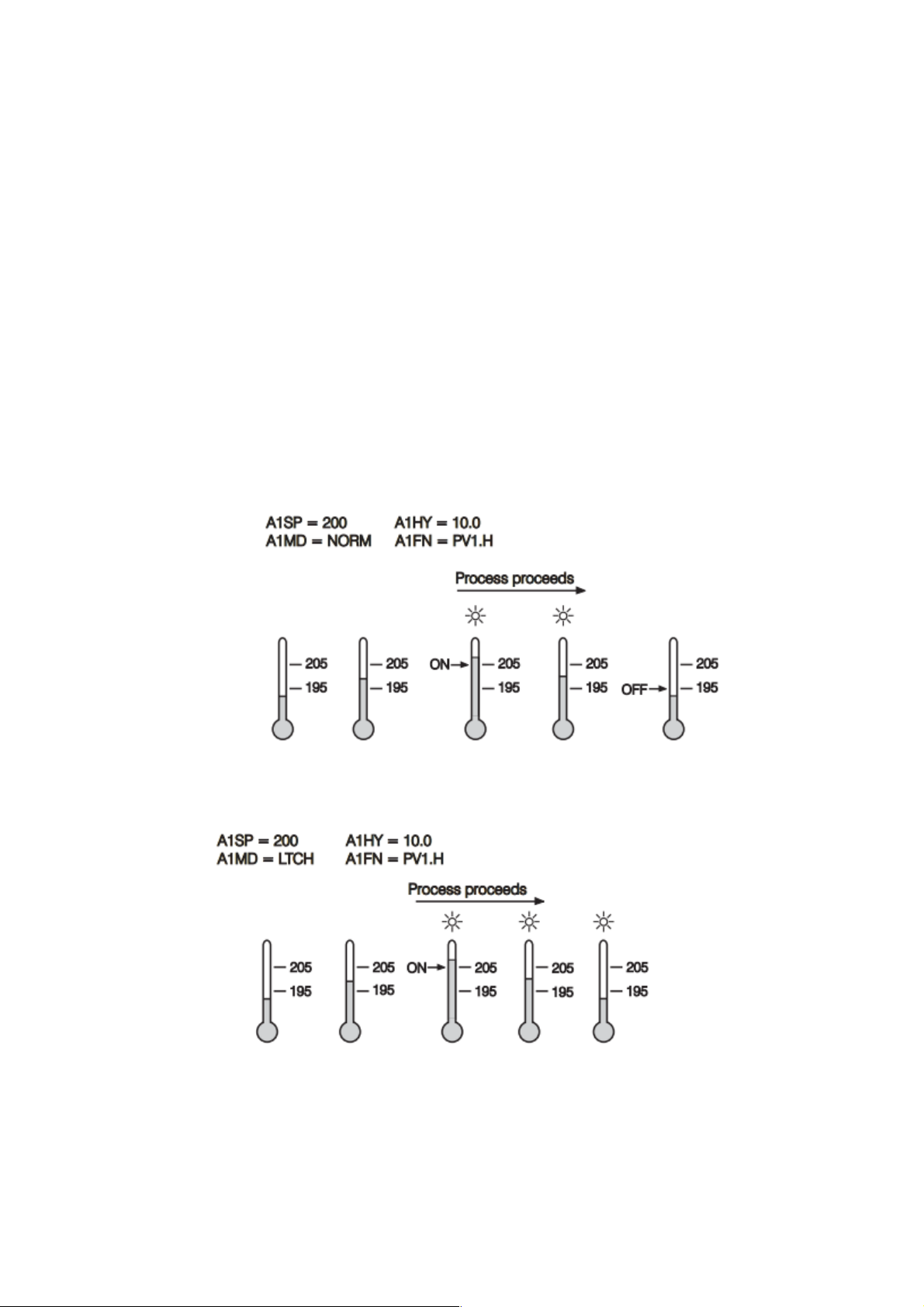
When a normal alarm is selected, the alarm output is de-energized in the non-alarm
condition and energized in an alarm condition.
Latching Alarm: A1MD = LTCH
If a latching alarm is selected, once the alarm output is energized, it will remain unchanged
even if the alarm condition is cleared. The latching alarms are disabled when the power is shut off
or if event input is applied with proper selection of EIFN.
Holding Alarm: A1MD = HOLD
A holding alarm prevents an alarm from power up. The alarm is enabled only when the
process reaches the set point value ( may be SP1 or SP2 ). Afterwards, the alarm performs
same function as normal alarm.
Latching / Holding Alarm: A1MD = LT .HO
A latching / holding alarm performs both holding and latching function.
Figure 4-36.Normal Process Alarm
Figure 4-37.Latching Process Alarm
Page 87 of 113
Page 88
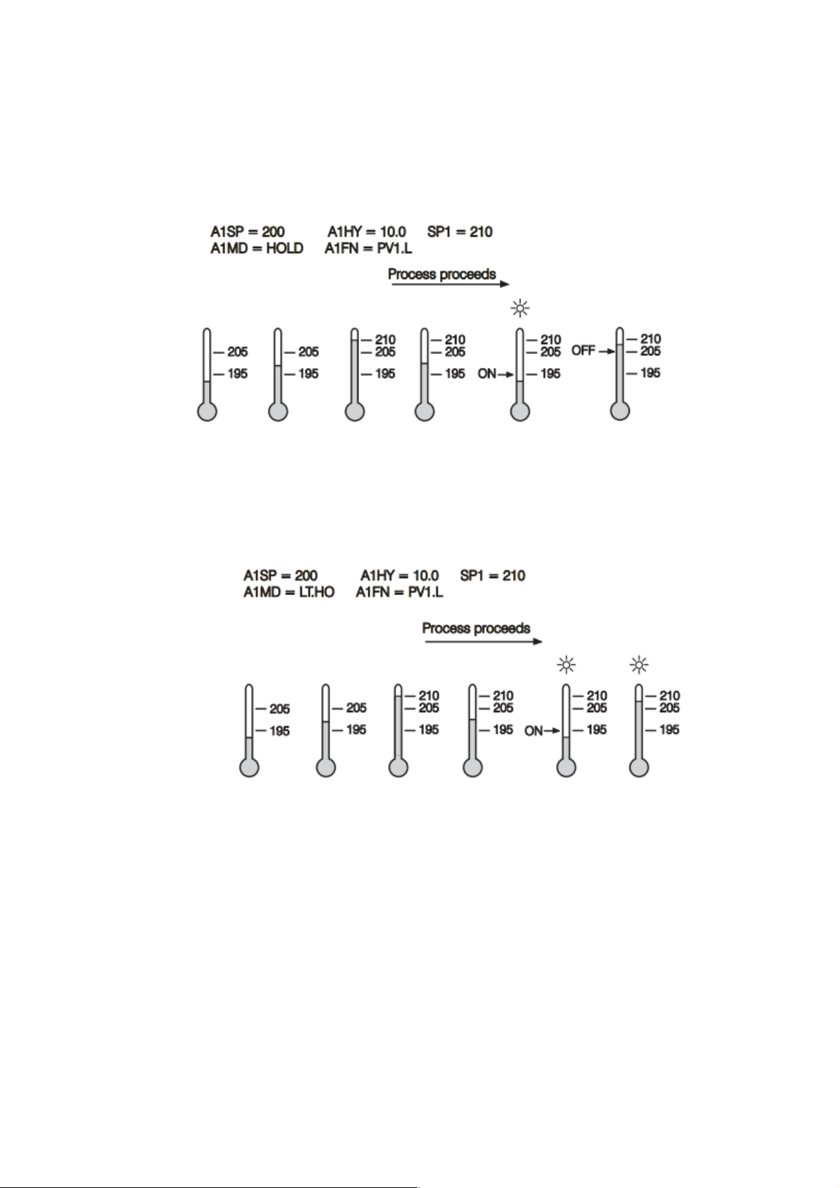
Figure 4-38.Holding Process Alarm
Although the above descriptions are based on alarm 1, the same conditions can be applied
to alarm 2.
4.3.1.1.4.13 Deviation Alarm
A deviation alarm alerts the user when the process deviates too far from set point.
The user can enter a positive or negative deviation value (A1DV, A2DV) for alarm 1 and alarm
2. A hysteresis value (A1HY or A2HY) can be selected to avoid interference problem of alarm
in a noisy environment. Normally, A1HY and A2HY can be set with a minimum (0.1) value.
Trigger levels of alarm are moving with set point.
Figure 4-39.Latching / Holding Process Alarm
Page 88 of 113
Page 89
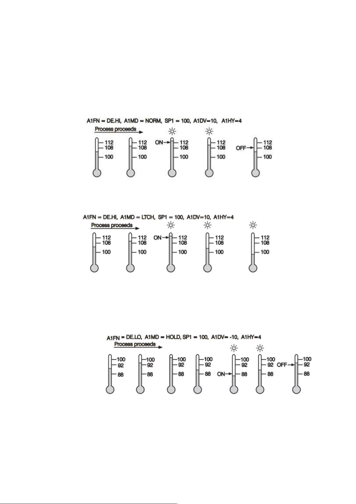
For alarm 1, Trigger levels=SP1+A1DV 1/2 A1HY.
For alarm 2, Trigger levels=SP1+A2DV 1/2 A2HY.
A1SP and/or A2SP are hidden if alarm 1 and/or alarm 2 are set with deviation alarm. One
of 4 kinds of alarm modes can be selected for alarm 1 and alarm 2. These are Normal alarm,
latching alarm, Holding alarm and Latching/Holding alarm.
Figure 4-40.Normal Deviation Alarm
Figure 4-41.Latching Deviation Alarm
Figure 4-42.Holding Deviation Alarm
Page 89 of 113
Page 90
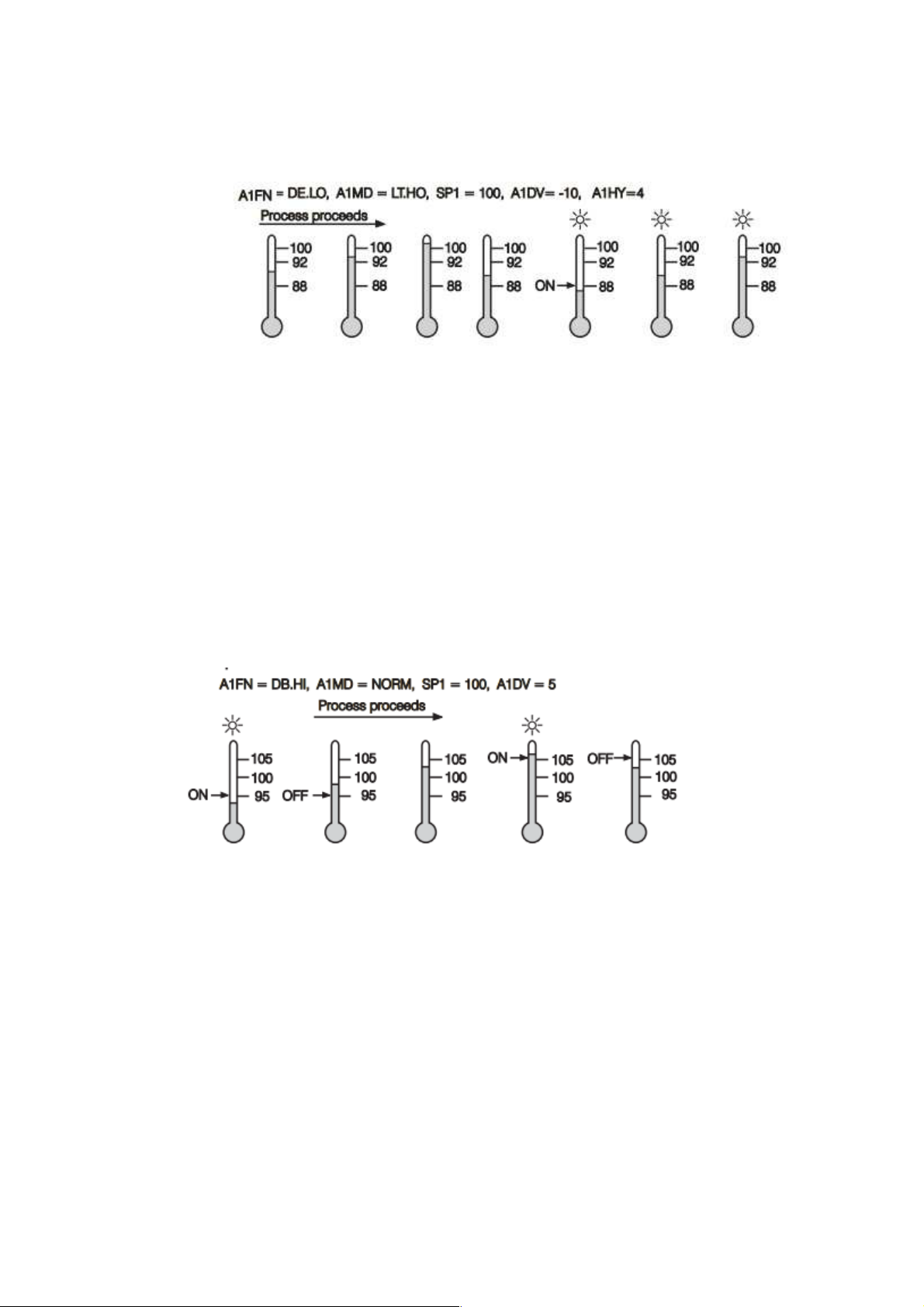
Figure 4-43.Latching/Holding Deviation Alarm
4.3.1.1.4.14 Deviation Band Alarm
A deviation band alarm presets two reference levels relative to set point. Two types of
deviation band alarm can be configured for alarm 1 and alarm 2. These are deviation band high
alarm (A1FN or A2FN select DB.HI) and deviation band low alarm (A1FN or A2FN select DB.LO).
A1SP and A1HY are hidden if alarm 1 is selected with deviation band alarm. Similarly, A2SP and
A2HY are hidden if alarm 2 is selected with deviation band alarm. Trigger levels of deviation band
alarm are moving with set point. For alarm 1, trigger levels=SP1± A1DV. For alarm 2, trigger
levels=SP1 ±A2DV.One of 4 kinds of alarm modes can be selected for alarm 1 and alarm 2.
These are Normal alarm, latching alarm, Holding alarm and Latching/Holding alarm.
Figure 4-44.Normal Deviation Band Alarm
Page 90 of 113
Page 91
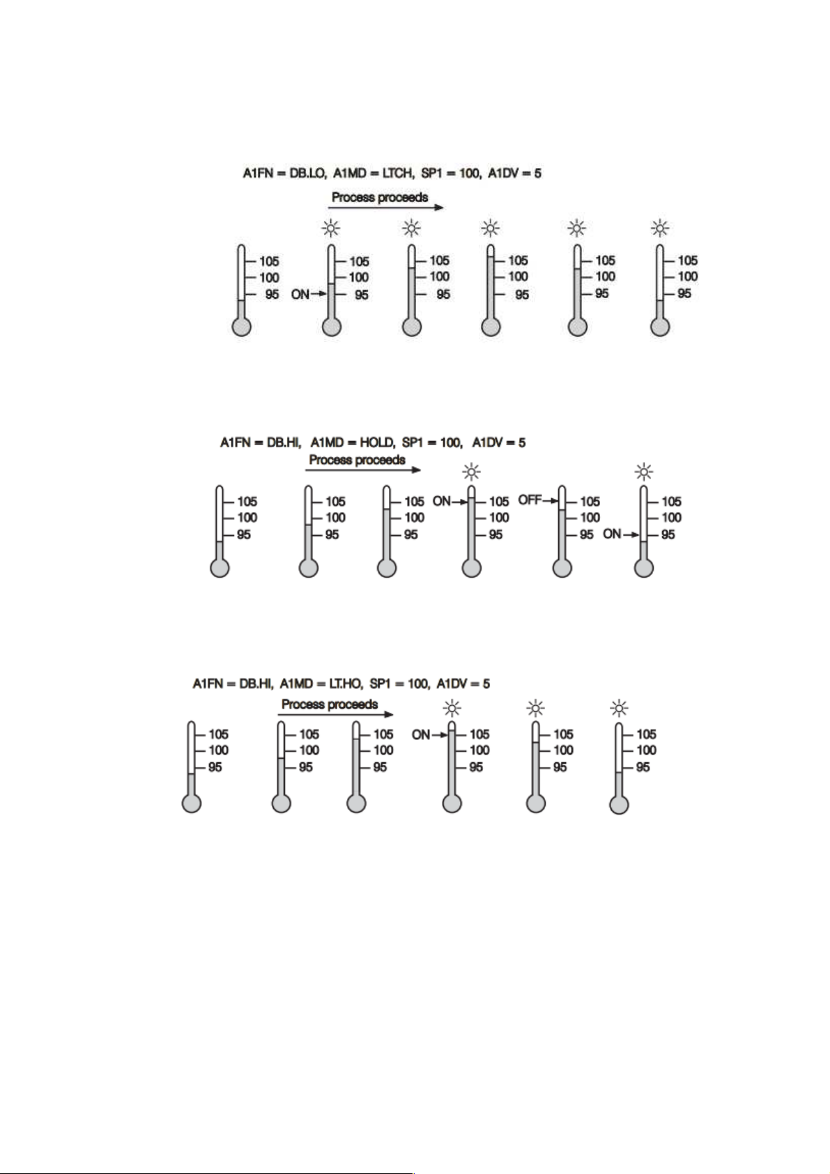
Figure 4-45.Latching Deviation Band Alarm
Figure 4-46.Holding Deviation Band Alarm
4.3.1.1.4.15 Event Input
The Event input accepts a digital type signal. Three types of signals can be connected to
event input. These are
Relay or switch contacts
Open collector pull low
Figure 4-47.Latching/Holding Deviation Band Alarm
Page 91 of 113
Page 92

TTL logic level
One of ten available functions can be chosen by using (EIFN) contained in setup menu.
NONE: Event input No function. If chosen, the event input function is disabled. The
controller will use PB1, TI1 and TD1 for PID control and SP1 (or other values
determined by SPMD) for the set point.
SP2: If chosen, the SP2 will replace the role of SP1 for control. SP2: If chosen, the
SP2 will replace the role of SP1 for control.
PID2: If chosen, the second PID set PB2, TI2 and TD2 will be used to replace PB1,
TI1 and TD1 for control.
PID2: If chosen, the second PID set PB2, TI2 and TD2 will be used to replace PB1,
TI1 and TD1 for control.
SP.P2: If chosen, the SP2, PB2, TI2 and TD2 will replace SP1, PB1, TI1 and TD1
for c
NOTE: If the second PID set is chosen during Auto-tuning and/or Self-tuning
procedures, the new PID values will be stored in PB2, TI2 and TD2.
RS.A1: Reset Alarm 1 as the event input is activated. However, if alarm 1 condition
is still existent, the alarm 1 will be retriggered again while the event input is
released.
RS.A2: Reset Alarm 2 as the event input is activated. However, if alarm 2
conditions are still existent, the alarm 2 will be retriggered again while the event
input is released.
R.A1.2: Reset both Alarm 1 and Alarm 2 as the event input is activated. However,
if the alarm 1 and/or alarm 2 are still existent, the alarm 1 and/or alarm 2 will be
triggered again while the event input is released.
The RS.A1, RS.A2 and R.A1.2 are particularly suitable to be used for a Latching
and/or Latching/Holding alarms.
D.O1: Disable Output 1 as the event input is activated. The output 1 control
variable MV1 is cleared to zero.
D.O2: Disable Output 2 as the event input is activated. The output 2 control
variables MV2 is cleared to zero.
D.O1.2: Disable both Output 1 and Output 2 by clearing MV1 and MV2 values as
soon as the event input is activated.
Page 92 of 113
Page 93

When any of D.O1, D.O2 or D.O1.2 is selected for EIFN, the output 1 and/or output
2 will revert to their normal conditions as soon as the event input is released.
LOCK: All parameters are locked to prevent from being changed.
SP2F Function: Define format of SP2 value. If SP2F in the setup menu is selected
with ACTU, the event input function will use SP2 value for its second set point. If
SP2F is selected with DEVI, the SP1 value will be added to SP2. The sum of SP1
and SP2 (SP1+SP2) will be used by the event input function for the second set
point value. In certain applications it is desirable to move second set point value
with respect to set point 1 value. The DEVI function for SP2 provides a convenient
way in this case.
4.3.1.1.4.16 Second Set Point
In certain applications it is desirable to change the set point automatically without the need to
adjust the set point. You can apply a signal to event input terminals. The signal applied to event
input may come from a Timer, a PLC, and an Alarm Relay, a Manual switch or other devices.
Select SP2 for EIFN which is contained in setup menu. This is available only with the case that
SP1.2, MIN.R or HR.R is used for SPMD, where MIN.R and HR.R are used for the ramping
function.
Application 1: A process is required to be heated at a higher temperature as soon as its
pressure exceeds a certain limit. Set SPMD=SP1.2, EIFN=SP2 (or SP .P2 if the second PID is
required for the higher temperature too).The pressure gauge is switched ON as it senses a higher
pressure. Connect the output contacts of the pressure gauge to the event input. SP1 is set with a
normal temperature and SP2 is set with a higher temperature. Choose ACTU for SP2F.
Application 2: An oven is required to be heated at 300°C from 8.00 AM to 6.00 PM After 6.00
PM it is desirable to be maintained at 80°C. Use a programmable 24 hours cycle timer for this
purpose. The timer output is used to control event input. Set SPMD=SP1.2, and EIFN=SP2 (or
SP .P2 if the second PID is required to be used for the second set point).SP1 is set with 300°C and
SP2 is set with 80°C. Choose ACTU for SP2F. After 6.00 PM the timer output is closed. The event
input function will select SP2 (=80°C) to control the process.
4.3.1.1.4.17 Second PID Set
In certain applications the process characteristics is strongly related to its process value. The
Process Control Card provides two set of PID values. When the process is changed to different set
point, the PID values can be switched to another set to achieve an optimum condition.
The optimal PID values for a process may vary with its process value and set point. Hence if a
process is used for a wide range of set point, dual PID values are necessary to optimize the control
performance. If the first PID set is selected (event input is not applied) during auto-tuning
procedure, the PID values will be stored in PB1, TI1 and TD1. Similarly, if the second PID set is
selected (event input is applied while PID2 or SP.P2 is selected for EIFN) during auto-tuning, the
PID values will be stored in PB2, TI2 and TD2 as soon as auto-tuning is completed.
Page 93 of 113
Page 94
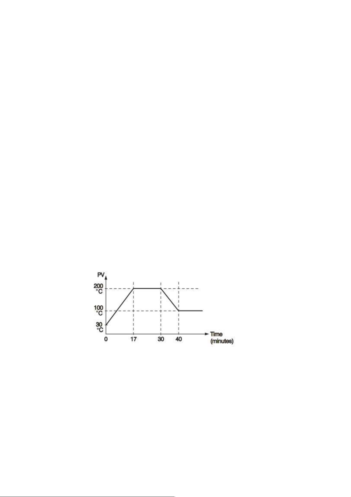
Application 1: Programmed by Set Point
Choose SP.P2 for EIFN then both set point and PID values will be switched to another set
simultaneously. The signal applied to event input may come from a Timer, a PLC, an Alarm Relay,
a Manual Switch or other devices.
Application 2: Programmed by Process Value
If the process value exceeds a certain limit, 500°C for example, it is desirable to use another
PID values to optimize the control performance. The user can use a process high alarm to detect
the limit of the process value. Choose PV1H for A1FN, A1MD selects NORM, adjust A1SP to be
equal to 500° C, and choose PID2 for EIFN. If the temperature is higher than 500°C, then alarm 1
is activated. The alarm 1 output is connected to event input; the PID values will change from PB1,
TI1 and TD1 to PB2, TI2 and TD2.
4.3.1.1.4.18 Ramp & Dwell
Ramp
The ramping function is performed during power up as well as any time the set point is
changed. Choose MINR or HRR for SPMD, the unit will perform the ramping function. The ramp
rate is programmed by using RAMP which is available in user configuration of Process Control
Card
Example without Dwell Timer
Select MINR for SPMD, IN1U selects °C, DP1 selects 1-DP, Set RAMP=10.0. SP1 is set
to 200°C initially, and changed to 100°C after 30 minutes since power up. The starting temperature
is 30° C. After power up the process is running like the curve shown below
Figure 4-48.Ramp Function
Note: When the ramp function is used, the lower display will show the current ramping
value. However it will revert to show the set point value as soon as the up or down key is touched
for adjustment. The ramping value is initiated to process value either power up or RAMP and /or
set point are changed. Setting RAMP to zero means no ramp function at all.
Dwell
The Dwell timer can be used separately or accompanied with a Ramp. If A1FN selects TIMR,
the alarm 1 will act as a dwell timer. Similarly, alarm 2 will act as a dwell timer if A2FN selects TIMR.
Page 94 of 113
Page 95
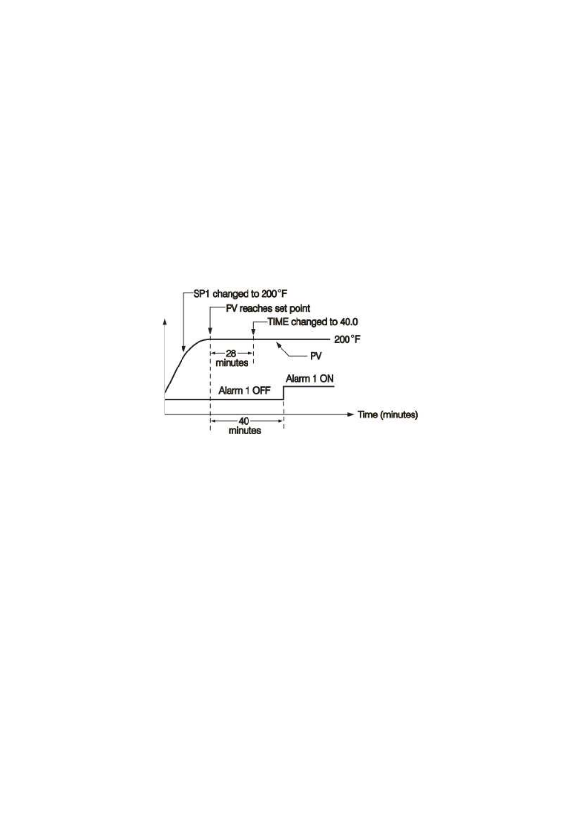
The timer is programmed by using TIME which is contained in Configuration menu. The Timer starts
to count as soon as the process reaches its set point, and triggers an alarm as time out. Here is an
example.
Example without Dwell Timer
Select TIMR for A1FN, IN1U selects F, DP1 selects NODP, Set TIME=30.0 SP1 is set to 400
F initially, and corrected to 200 F before the process reaches 200° F. As the process reaches set
point (i.e. 200°F) the timer starts to count. The TIME value can still be corrected without disturbing
the Timer before time out. The TIME is changed to 40.0 after 28 minutes since the process reached
its set point. The behavior of process value and alarm 1 are shown below.
Once the timer output was energized it will remain unchanged until power down or an event
input programmed for resetting alarm is applied.
Figure 4-49.Dwell Timer
Note: The TIMR can't be chosen for both A1FN and A2FN simultaneously; otherwise an error
code will produce.
Ramp &Dwell
A Ramp can be accompanied with a dwell timer to control the process. Here is an example.
Example Ramp & Dwell Timer
Select HRR for SPMD, IN1U selects PU, DP1 select 2-DP, Set RAMP=60.00 A2FN selects
TIMR, Set TIME=20.0 as power is applied the process value starts from 0.00 and set SP1=30.00,
SP2=40.00. The timer output is used to control event input.
Page 95 of 113
Page 96
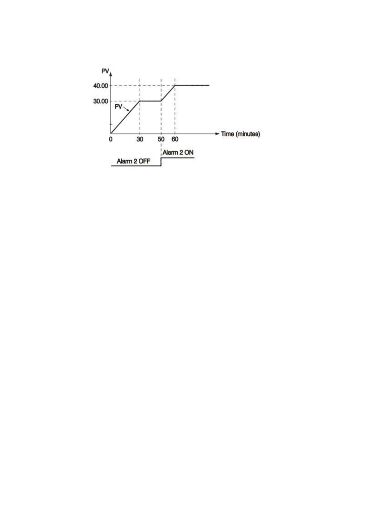
Figure 4-50.Ramp Accompanied with Dwell Timer
4.3.1.1.4.19 Remote Set Point
SPMD selecting PV1 or PV2 will enable the Process Control Card to accept a remote set
point signal. If PV1 is selected for SPMD, the remote set point signal is sent to Input 1, and
Input 2 is used for process signal input. If PV2 is selected for SPMD, the remote set point signal
is sent to Input 2, and Input 1 is used for process signal. To achieve this, set the following
parameters in the Configuration menu.
Case 1: Use Input 2 to accept remote set point
FUNC=FULL
IN2, IN2U, DP2, IN2L, IN2H, are set according to remote signal.
PVMD=PV1
IN1, IN1U, DP1, are set according to the process signal
IN1L, IN1H if available, are set according to the process signal
SPMD= PV2
Case 2: Use Input 1 to accept remote set point
FUNC=FULL
IN1, IN1U, DP1, IN1L, IN1H, are set according to remote signal.
PVMD=PV2
IN2, IN2U, DP2, are set according to the process signal
Page 96 of 113
Page 97
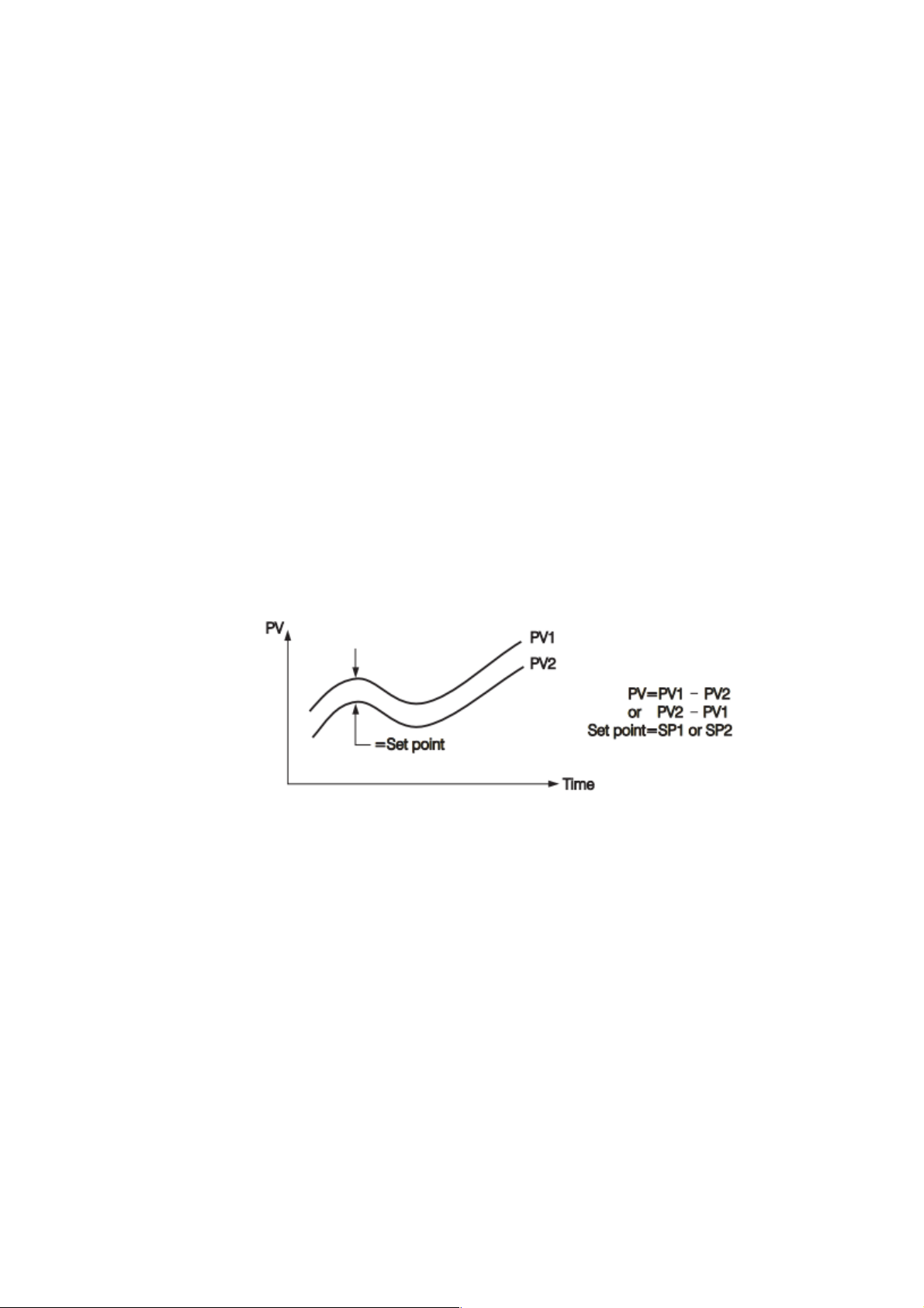
IN2L, IN2H if available, are set according to the process signal
SPMD= PV1
Note: If PV1 are chosen for both SPMD and PVMD, an Error Code will appear. If PV2 are
chosen for both SPMD and PVMD, an Error Code will appear. The user should not use these
cases, otherwise, the Process Control Card will not control properly.
4.3.1.1.4.20 Differential Control
In certain applications it is desirable to control second process such that its process value
always deviates from the first process with a constant value. To achieve this, set the following
parameter in the Setup menu.
FUNC=FULL
IN1, IN1L, IN1H are set according to input 1 signal
IN2, IN2L, IN2H are set according to input 2 signal
IN1U, DP1, IN2U, DP2, are set according to input 1 and input 2 signal
PVMD=P1-2 or P2-1
SPMD=SP1.2
The response of PV2 will be parallel to PV1 as shown in the following diagram
Figure 4-51.Relationship Between PV1 & PV2 for Differential Control
The PV display will indicate PV1-PV2 value if P1-2 is chosen for PVMD or PV2-PV1 value
if P2-1 is chosen for PVMD. If the user needs PV1 or PV2 to be displayed instead of PV, they can
use the Display Mode to select PV1 or PV2 to be viewed
If PVMD selects P1-2 or P2-1, while SPMD selects PV1 or PV2, an Error Code will appear.
In this case the signals used for input 1 and input 2 should be the same unit and same decimal
point, that is, IN1U=IN2U, DP1=DP2, otherwise Error Code will appear.
Page 97 of 113
Page 98
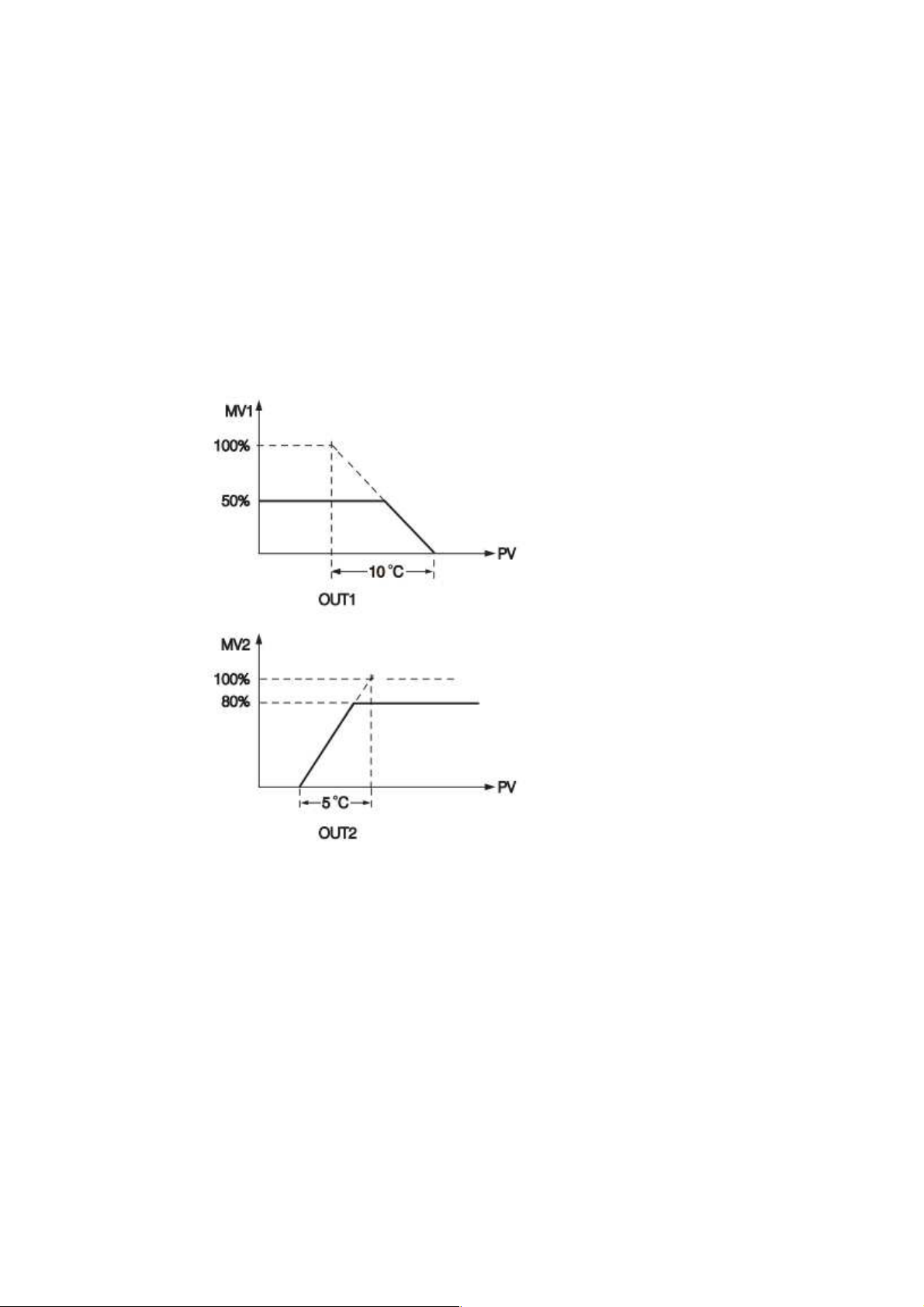
4.3.1.1.4.21 Output Power Limit
In certain system the heater (or cooler) is over-designed such that the process is too heavily
heated or cooled. To avoid an excessive overshoot and/or undershoot the user can use the Power
Limit function. Output 1 power limit PL1 is contained in Configuration. If output 2 is not used for
cooling (that is COOL is not selected for OUT2), then PL2 is hidden. If the controller is used for
ON-OFF control, then both PL1 and PL2 are hidden
Example:
OUT2=COOL, PB1=10.0°C, CPB=50, PL1=50, PL2=80 the output 1 and output 2 will act as
following curves
NOTE:
The adjusting ranges of MV1 (H) and MV2 (C) for manual control and/or failure transfer are not
limited by PL1 and PL2.
4.3.1.1.4.22 Digital Filter
In certain application the process value is too unstable to be read. To improve this
programmable low pass filter incorporated in this Process Control Card can be used. This is a
first order filter with time constant specified by FILT parameter which is contained in setup menu.
The default value of FILT is 0.5 sec. before shipping. Adjust FILT to change the time constant
Figure 4-52.Power Limit Function
Page 98 of 113
Page 99
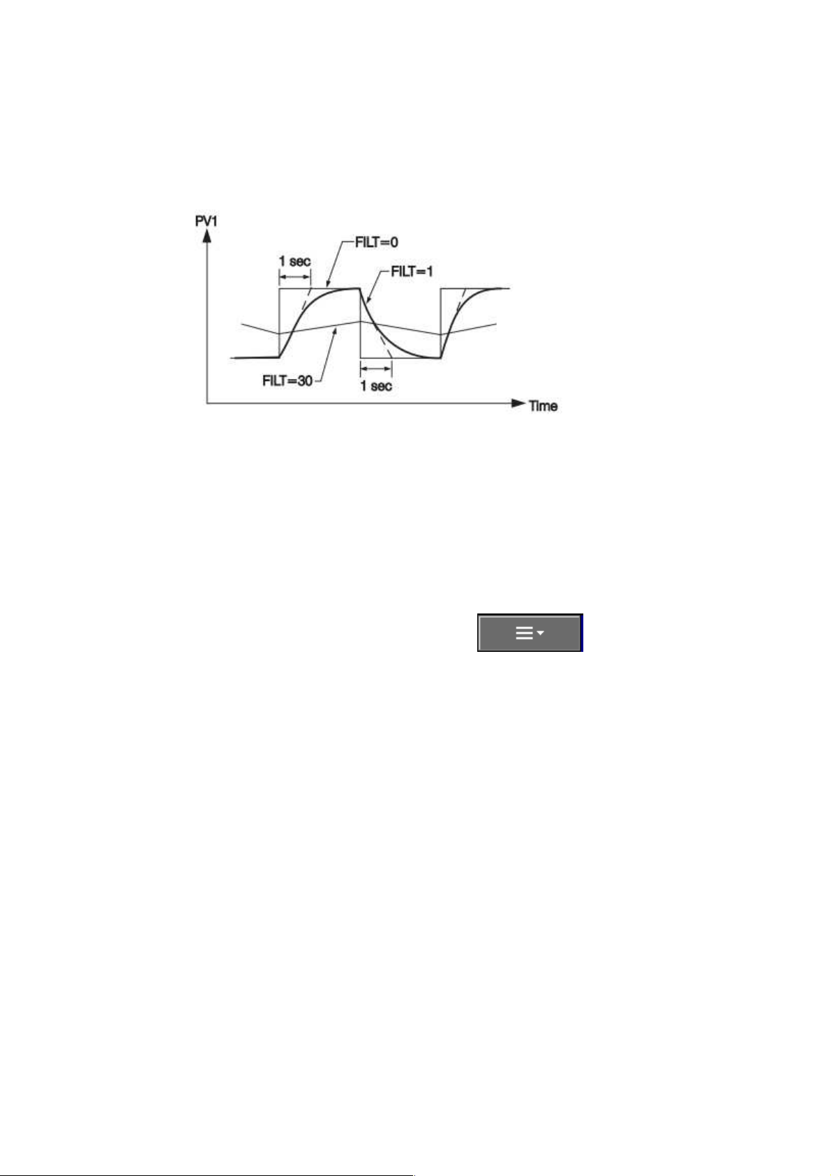
from 0 to 60 seconds. 0 second represents no filter is applied to the input signal. The filter is
characterized by the following diagram.
Figure 4-53.Filter Characteristics
Note:
The Filter is available only for PV1, and is performed for the displayed value only. The
controller is designed to use unfiltered signal for control even if Filter is applied. A lagged (filtered)
signal, if used for control, may produce an unstable process.
4.3.1.1.4.23 Auto-Tuning and Manual Tuning
The Auto-tuning and Manual tuning can be executed by pressing the mode button in the
Process control module realtime display page. Press and Press Real Time
and Press C1 to access the Process Control module real time display page.
Press Mode and select Auto-tuning to perform auto tuning for the process.During Auto-
tuning process the PV display will blink continuously.
Press Mode and select Manual tuning to perform manual tuning for the process.In this the
user can control the process manually by adjusting the output value manually.
Press Back to exit auto tuning or manual tuning when it is in progress.
Page 99 of 113
Page 100
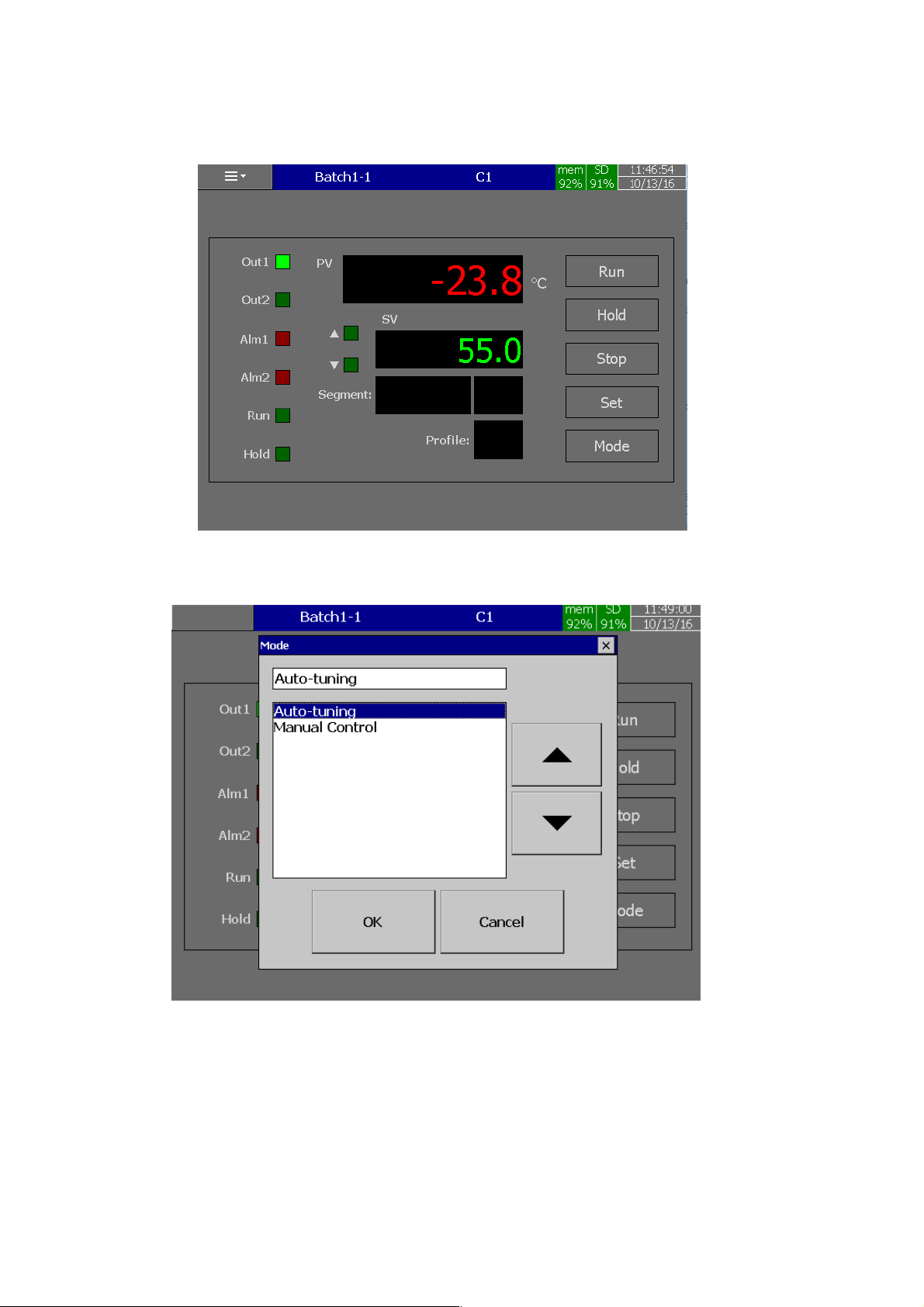
Figure 4-54.Process Control Module Real time
Figure 4-55.Auto-Tuning
Page 100 of 113
 Loading...