

Page 1
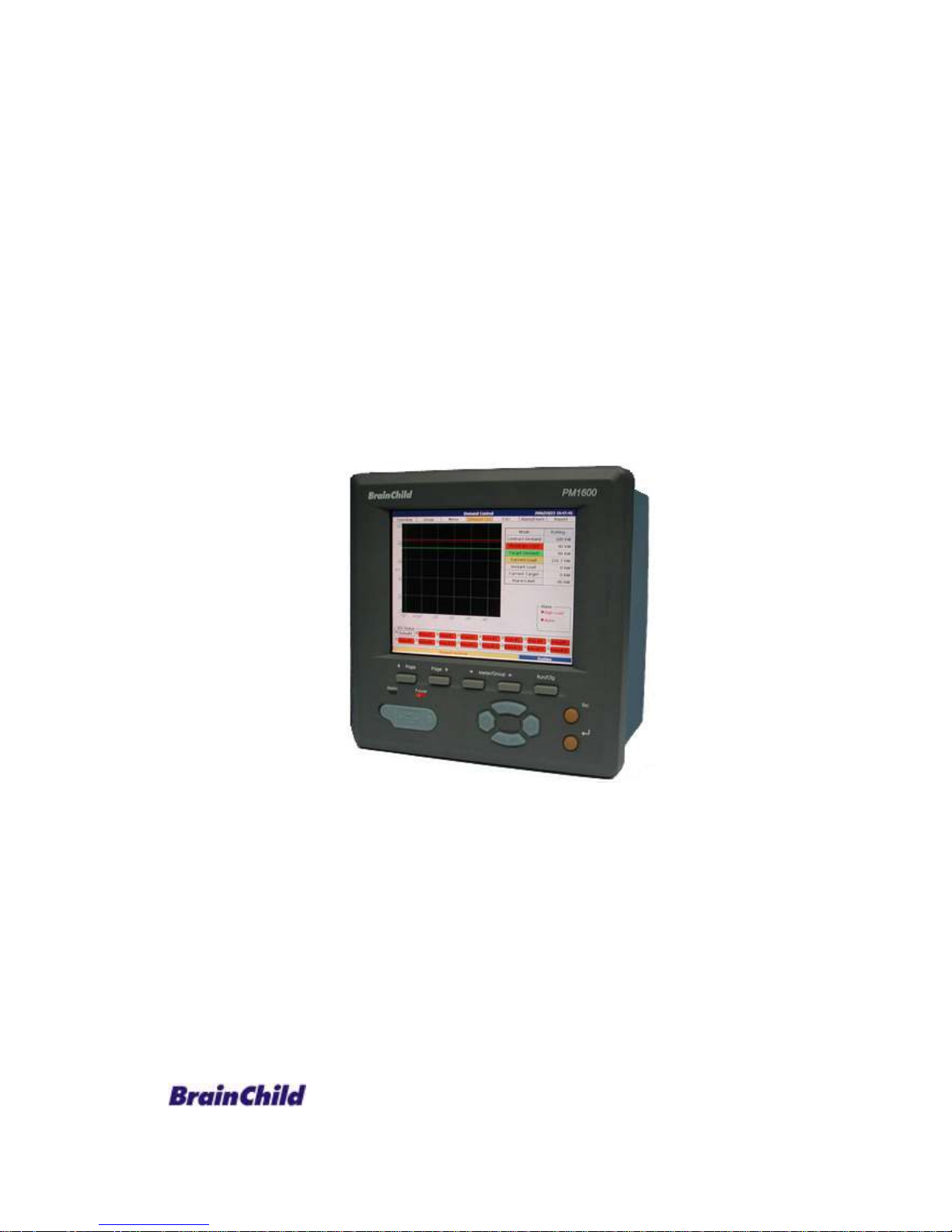
User Manual
Power Manager
PM1600
UMPM1600A
Brainchild Electronic Co., Ltd.
V1.3, 02/2007
Page 2

2
Content
Chapter 1 Introduction………………………………………………………………….5
1.1 Introduction of PM1600………………………………………………………………5
1.2 Caution…………………………………………………………………………………..5
1.2.1 Danger………………………………………………………………………………5
1.2.2 PRODUCT WARRANTY & CUSTOMER SUPPORT…………………………5
1.2.3 LIMITATION OF WARRANTY……………………………………………………5
Chapter 2 Specifications………………………………………………………………..6
2.1 Main Features..........................................................................................7
2.2 Hardware Specification……………………………………………………………….8
2.3 Software Specification…………………………………………………………………9
Chapter 3 Installation and Wiring……………………………………………………12
3.1 Unpacking………………………………………………………………………………12
3.2 Installation……………………………………………………………………………...12
3.2.1 Panel Mount……………………………………………………………………….12
3.3 Wiring…………………………………………………………………………………….15
3.3.1 Rear terminal……………………………………………………………………...15
3.3.2 Digital output wiring………………………………………………………….…16
3.3.3 RS485 wiring………………………………………………………………………16
Chapter 4 Using the PM1600……………………………………..…………………..17
4.1 Ways to operate PM1600…………………………………………………………….17
4.1.1 Operation through panel keys of PM1600 Host Machine……………….17
4.1.2 Operation through PM1600 Host Machine with USB mouse…………..18
4.1.3 Operating through Web Client………………………………………………...18
4.2 General Operations……………………………………………………………………20
4.3 Function Trees........................................................................................23
4.3.1 Runtime Mode..................................................................................23
4.3.2 Configuration Mode...........................................................................24
4.4 Connecting the PM1600 with client PC…………………………………………..25
4.4.1 Pier to pier connection…………………………………………………………..25
4.4.2 Network Connection……………………………………………………………..25
4.5 Setting the PM1600……………………………………………………………………30
Chapter 5 Run Mode……………………………………………………………………..31
5.1 System Overview………………………………………………………………………31
5.2 Meter Group or Meter Display……………………………………………………..32
5.2.1 Digital Display……………………………………………………………….……32
5.2.2 Bar Chart Display………………………………………………………………..33
Page 3

3
5.3 Relay Status…………………………………………………………………….………34
5.4 Individual Meter Display…………………………………………………………….35
5.4.1 Digital Display…………………………………………………………………….35
5.4.2 Summary Display………………………………………………………………..36
5.4.3 Real time Trend…………………………………………………………………..38
5.4.4 Historical Trend…………………………………………………………………..39
5.4.5 Graphical Display………………………………………………………………..40
5.5 Demand Control……………………………………………………………………….43
5.5.1 Blocking mode……………………………………………………….……………43
5.5.2 Rolling mode……………………………………………………………………….44
5.6 Time of Use……………………………………………………………………………...45
5.7 Alarm/Event Log………………………………………………………………………46
5.8 Report……………………………………………………………………………………47
5.8.1 Aggregate Daily Report………………………………………………………….47
5.8.2 Aggregate Monthly Report………………………………………………………48
5.8.3 Sub-Meter Daily Report…………………………………………………………49
5.8.4 Sub-Meter Monthly Report……………………………………………………..50
Chapter 6 Configuration Mode………………………………………………………..51
6.1 System Setup…………………………………………………………………………..51
6.1.1 Date/Time Setup…………………………………………………………………52
6.1.2 Serial Communication Setup………………………………………………….53
6.1.3 Mailing List Setup………………………………………………………………..54
6.1.4 Mail Server Setup…………………………………………………………………57
6.1.5 TCP/IP Setup……………………………………………………………………..59
6.1.6 Password Modification…………………………………………………………..61
6.1.7 User’s Data Setup………………………………………………………………..61
6.2 Meter Setup……………………………………………………………………………..64
6.2.1 Basic Setup………………………………………………………………………..65
6.2.2 Measure Setup……………………………………………………………………65
6.2.3 Alarm Setup…………………………………………………………………….…66
6.2.4 Trend Setup/ DATA Recording………………………………………………..68
6.3 TOU Setup………………………………………………………………………………69
6.3.1 Season Setup……………………………………………………………………..70
6.3.2 Day Type Setup…………………………………………………………………..71
6.3.3 Holidays Setup……………………………………………………………………73
6.3.4 Rate Type Setup…………………………………………………………………..73
6.3.5 Tariff Band Setup…………………………………………………………………77
6.4 Schedule Setup………………………………………………………………………..79
6.4.1 Season Setup……………………………………………………………………...80
6.4.2 Day Type Setup……………………………………………………………………81
6.4.3 Recurring Holidays Setup………………………………………………………82
6.4.4 Special Day Type Setup…………………………………………………………83
Page 4

4
6.4.5 Day Plan Setup…………………………………………………………………..84
6.4.6 Day type Setup using Calendar………………………………………………85
6.5 Demand Control Setup………………………………………………………………87
6.5.1 Parameter Setup…………………………………………………………………88
6.5.2 Load Shed Setup…………………………………………………………………91
6.6 Group Setup……………………………………………………………………………94
6.7 Data Backup……………………………………………………………………………95
Appendix…………………………………………………………………………………….96
Abbreviation………………………………………………………………………………96
Page 5

5
Chapter 1 Introduction
1.1 Introduction of PM1600
PM1600 is designed for modern industrial sites, commercial facilities and
utilities power management. By integration of power monitoring, demand
control, power quality analysis, report generation and communication, PM1600
fulfills all daily power management requirements. Combines the state of art
embedded system with information networking technologies, a high
performance power supervisory control system can be built at a fairly low cost.
1.2 Caution
1.2.1 Danger
The PM1600 meter contains hazardous voltages. The meter should never be
disassembled. Failure to observe this practice can result in serious injury or
death. Any work on or near energized meters, meter sockets, or other metering
equipment can present a danger of electrical shock. It is strongly recommended
that all work should be performed only by qualified industrial electricians and
metering specialist. Brainchild assumes no responsibility if your electrical
installer does not follow the appropriate national and local electrical codes.
1.2.2 PRODUCT WARRANTY & CUSTOMER SUPPORT
Brainchild Electronic Co., Ltd. warrants all products free from defects in
material and workmanship for a period of one year from the date of shipping in
Taiwan.
Please have the serial number and a detailed problem description available
when you report any defective. If the problem concerns a particular reading,
please have all meter readings available. When returning any merchandise to
Brainchild, an approval RMA number is required.
1.2.3 LIMITATION OF WARRANTY
This warranty does not apply to defects resulting from unauthorized
modification, misuse, or use for reasons other than electrical power monitoring.
The supplied meter is not a user-serviceable product.
Page 6

6
Chapter 2 Detail Specifications
Power 85~240VAC, 47~63Hz, 60VA, Maximum 23W
Display 6.4” TFT LCD, 640 x 480 pixel resolution, 24 bits colors
Memory
64 MB RAM , 32 MB Flash , 16 MB DOC , RTC(Battery
back-upped)
Interface USB: Host Port x1
Keypad: Function Key x7、Arrow Key x4
LEDx2
Digital Output Ports: 16
Contact Form: Normal on (N.O.)(form A)
Relay Rating: 5A/240 VAC, life cycles 200,000 for resistive
load
COMM Interface: RS-485 x 1
Protocol: ModBus over serial line
Standard
Ethernet
Communication
Protocol: ModBus over TCP/IP
Ports: Ethernet = 10/100Mbps Base T x 2
Environmental
& Physical
Operation Temperature: 5℃to 50℃
Storage Temperature: -25℃ to 60℃
Humidity: 20 to 80%RH (non-condensing)
Dimensions: 196mm (W) x 196mm (H) x 135mm (D) for panel
mount
Approval
Standards
Safety:
Protective Class:
EMC: Emission: EN61326 (EN55022 class A, EN61000-3-2,
EN61000-3-3)
Immunity: EN61326 (EN61000-4-2, EN61000-4-3,
EN61000-4-4,EN61000-4-5,EN61000-4-6,
EN61000-4-8, EN61000-4-11)
Page 7

7
2.1 Main Features
Manage up to 16 units of power transducer
Flexible field communication interfaces (Ethernet and RS485) for different
power transducer connection
Rich electricity parameters and power quality display for main and
sub-feeder transducers
Easy integrated with 3rd party supervisory control systems
Remote power monitoring and control via intranet/internet
Electricity demand control with 16 channel load shedding
Multi-tariff management with TOU (Time-of-Use rate)
Built in web server remote monitoring and control & data download
Automatic report and alarm status sending by E-mail
Page 8

8
2.2 Hardware Specification
1. Power source:85~240VAC, 47~63Hz, 60VA, max. 23W
2. Display:6.4’’ TFT LCD, 640x480 pixels, 260,000 color
3. Memory:64MB, 32MB Flash, 32MB Disc on chip (DOC)
4. Memory Storage Module:
(1)DOC:32MB/64MB to store V,I,P…etc. 54 real time power data for over
1 year(up to DOC capacity option), multi-tariff TOU report up to
3years and over 1024 alarm and event records.
(2)Support USB flash driver
5. Interface:
(1)USB Host Port x 1:to connect mouse, key board or flash drive
(2)Key:7function keys, 4 navigation keys.
6. Communication Module:
(1)RS485 x 1, communication protocol:Modbus RTU
(2)Ethernet interface(10/100Mbps Base T x 2), communication protocol:
HTTP, SMTP
7. Outputs Interface:
(1)16 digital control outputs(no voltage, normal open, 5A/240V)
(2)Control Indicator x 1(Red LED):Alarm use
(3)power Indicator x 1
Page 9

9
2.3 Software Specification
1. Power demand control:
(1)Provide both blocking and rolling mode to calculate demand control.
(2)Provide shedding modes with a combination of sequence and priority
load shedding.
(3)Real time display of :
(a)control capacity
(b)selected control mode
(c)current demand
(d)average demand
(e)demand control parameters
(f)status of demand control
(g)manual load shedding
2. Monitoring of power measurement:
(1)display of real time values for each meters including:Voltage, current,
power…etc. up to 54 real-time values.
(2)digital or bar chart display for each real-time measurement data.
3. Monitoring of power quality:instant monitoring of harmonic distribution,
THD, power factor and voltage variation for each channel.
4. Display of real-time and historic trend:
(1)real-time trend display :to display trend of power information set by
users.
(2)historic display trend:
(a)to display historic trends of power consummation set by users.
(b)over a year of recorded data based on 15minuts data rate(up to
DOC capacity option).
5. Report inquiry
(1)Main Meter:
( a ) various power information at different tariff can be recorded
separately.
(b) recorded information include:kWh, kvah, maximum demand, and
happening time, average and standard deviation of phase voltage
and max. and min. power factor with happening time.
(c)300 days of daily report storage.
Page 10

10
(d)24 months of monthly report storage.
(2)Sub-meter:
( a ) various power information at different tariff can be recorded
separately.
(b) recorded information include:kWh, kvah, maximum demand, and
happening time, average demand and load ratio.
(c)300 days of daily report storage.
(d)24 months of monthly report storage.
6. Alarm and event record
(1)Up to 29 different type of alarm(such as:over voltage, over demand,
phase imbalance, THD…etc.).
(2)On-off and time duration of each DO and system power.
(3)Up to 1024 alarm on event record.
(4)Auto email to decimated person while alarm table place.
7. Schedule control:devices can be controlled according to the pre-set season,
date and hours.
8. System setup
(1)Communication setup.
(2)Network setup.
(3)Email setup.
(4)System time and screen protection time set up.
9. Meter setup
(1)Setup of meter address and tag name.
(2)TCP/IP ratio setup.
(3)Wiring setup.
(4)Table setup for recording information.
10. Setup for multiple tariff TOU management
(1)Start and end date setup for each season.
(2)Date type setup.
(3)Setup for recurring and non-recurring holidays.
(4)Start and end time for rate type setup(peak, non-peak rate).
11. Demand control setup
(1)according to the rate type of TOU to set up:
(a)Contracted demand capacity.
(b)Target demand.
Page 11

11
(c)Alarm limit.
(d)Load shedding limit.
(2)Setup of demand control parameters:
(a)calculation algorithm.
(b)time interval of calculation.
(c)load shedding mode(sequence or priority mode).
(3)determine of load shedding mode and their involved control DO.
12. Schedule control setup
(1)Start and end time setup for each season.
(2)Date type setup.
(3)Setup for recurring holidays.
(4)calendar setup.
(5)Setup on/off time for each designated DO.
13. Information backup:historic date, reports, alarm and event records all can
be back upped through USB flash drive.
14. Remote monitoring and setup
(1)Through web browser, real time values of each meter can be monitored
and modified remotely(No additional software is required).
(2)Through web browser, system parameters can be configured.
(3)Through web browser, historic data, reports, alarm and event records
can be downloaded and saves.
Page 12
12
Chapter 3 Installation and Wiring
3.1 Unpacking
If any damage been is found while unpacking, the user should contact the local
representative at once. It is suggested that the special packaging is suggested to
retain for possible future requirement.
3.2 Installation
Remove stains from this equipment using a soft, dry cloth. Don’t use
harsh chemicals, volatile solvent such as thinner or strong detergents to clean
the equipment in order to avoid deformation.
The PM1600 is designed for indoor use and not in any hazardous area. It should
be kept away from shock, vibration, and electromagnetic fields like such as
variable frequency drives, motors and transformers.
It is intended to be operated in the following environment:
Pollution Degree Level II IEC1010-1( EN61010-1 )
Temperature 5 ~ 50 ˚C
Humidity 20 ~ 80 % RH (non-condensing)
Power 90 ~ 240 VAC, 50/60 Hz
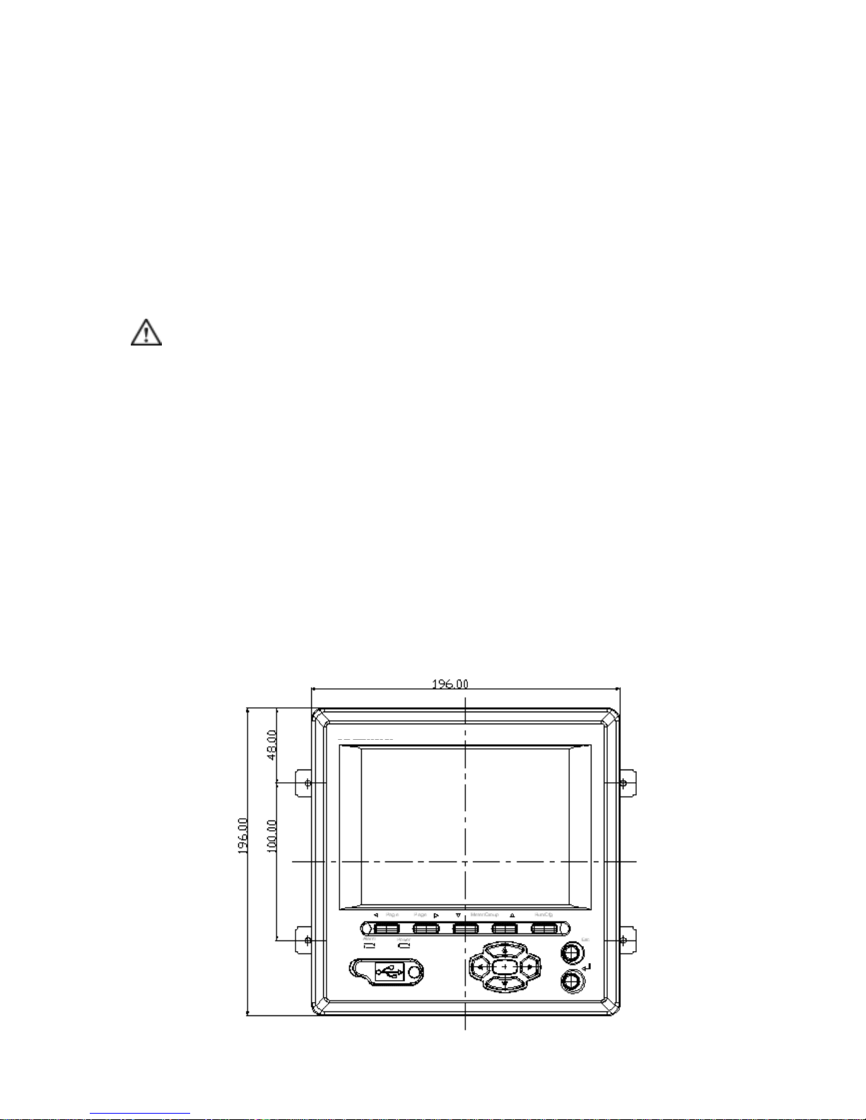
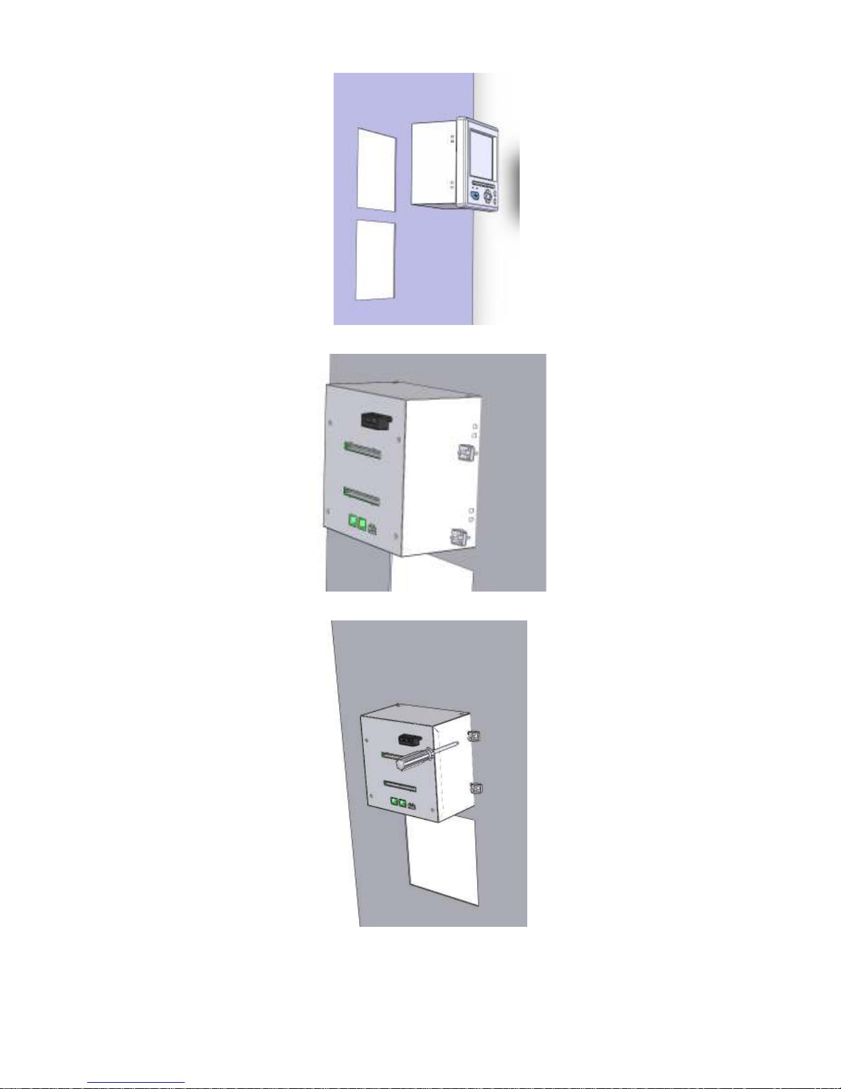
3.2.1 Panel Mount
The front side
Page 13
13
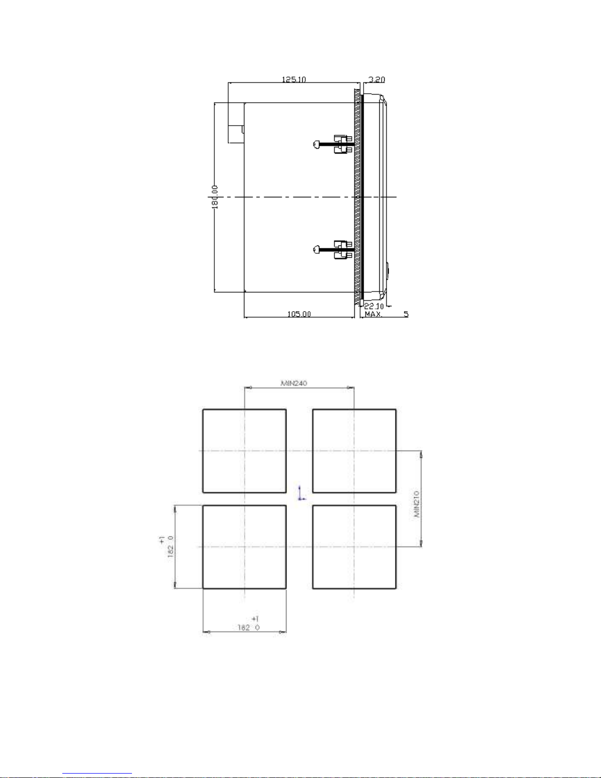
The left side
Panel Cutout
Page 14
14
Page 15
15
3.3 Wiring
Wiring Precautions
1. Care must be taken to ensure that maximum voltage rating specified on the
label is not exceeded.
2. It is recommended that near the equipment an external fuse and an external
switch rated at 2A/250 VAC should be equipped.
3. Beware not to over tighten the terminals screws. The torque should not
exceed 0.7 N-m ( 6.3 Lb-in or 7.1 Kg F-cm ).
4. Connect a grounding conductor with 1.6mm diameter minimum to provide
protective grounding prior to turning on the equipment.
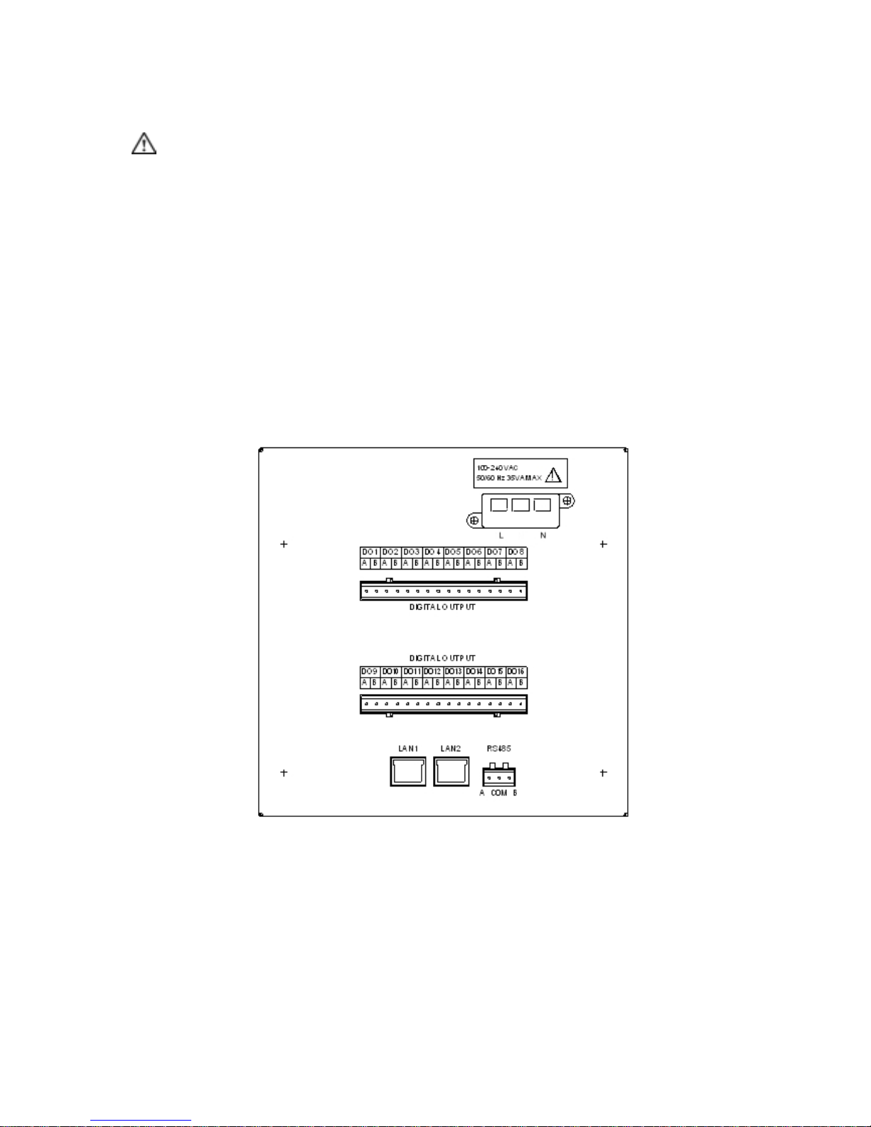
3.3.1 Rear terminal
LAN1: To connect with Transducers over Ethernet network
LAN2: To connect with PC for web server function
Page 16
16
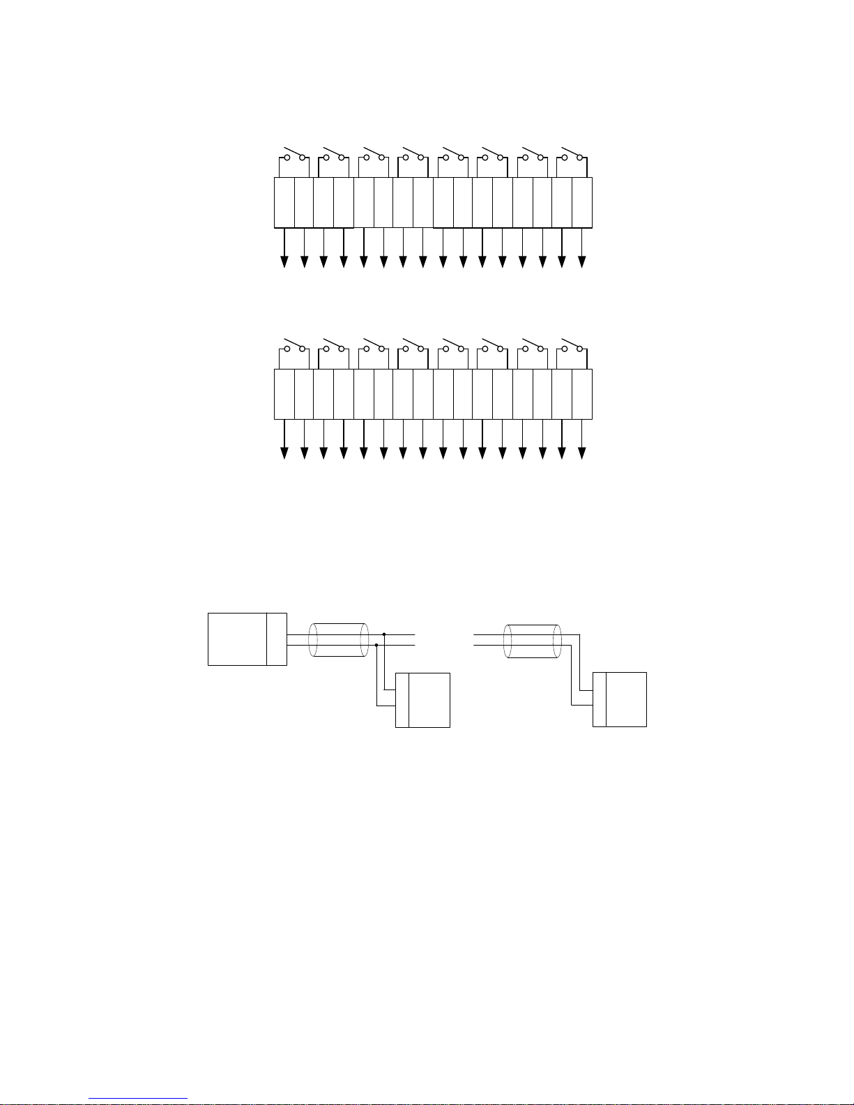
3.3.2 Digital output wiring
A1B1A2B2A3B3A4B
4A5B5A6B6A7B7A8B8
O
U
T
8
O
U
T
7
O
U
T
6
O
U
T
5
O
U
T
4
O
U
T
3
O
U
T
2
O
U
T
1
A9B
9
A
1
0
B
1
0
A
1
1
B
1
1
A
1
2
B
1
2
A
1
3
B
1
3
A
1
4
B
1
4
A
1
5
B
1
5
A
1
6
B
1
6
O
U
T
1
6
O
U
T
1
5
O
U
T
1
4
O
U
T
1
3
O
U
T
1
2
O
U
T
1
1
O
U
T
1
0
O
U
T
9
3.3.3 RS485 wiring
A
B
A
B
PM1600
Transducer
A
B
Transducer
․ ․ ․․․
․ ․ ․ ․ ․
․ ․ ․․․
Page 17
17
Chapter 4 Using the PM1600
In this chapter, focus will be given on things that you should understand before
you actually start setting PM1600, including method of entering data,
procedure, function trees.
4.1 Ways to operate PM1600
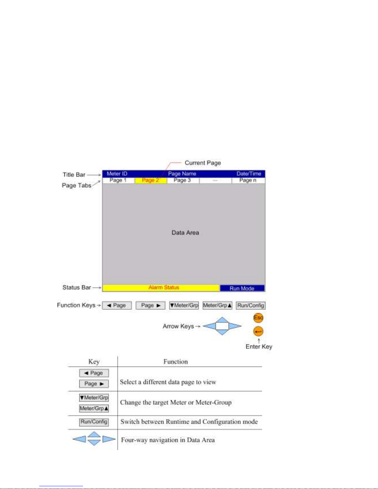
4.1.1 Operation through panel keys of PM1600 Host Machine
Press the function keys on the front panel to operate the PM1600.
Page 18

18
If entering numbers or letters are required, the screen will pop-up a screen
keyboard. Simply use navigation keys and enter key to complete the filling.
4.1.2 Operation through PM1600 Host Machine with USB mouse
Using USB mouse to operate PM1600, simply move the cursor to the desire item
and click the button to access, like using the mouse of PC. You can use the hard
key mixed with soft button by mouse at the same time which make you operate
the PM1600 in the field conveniently.
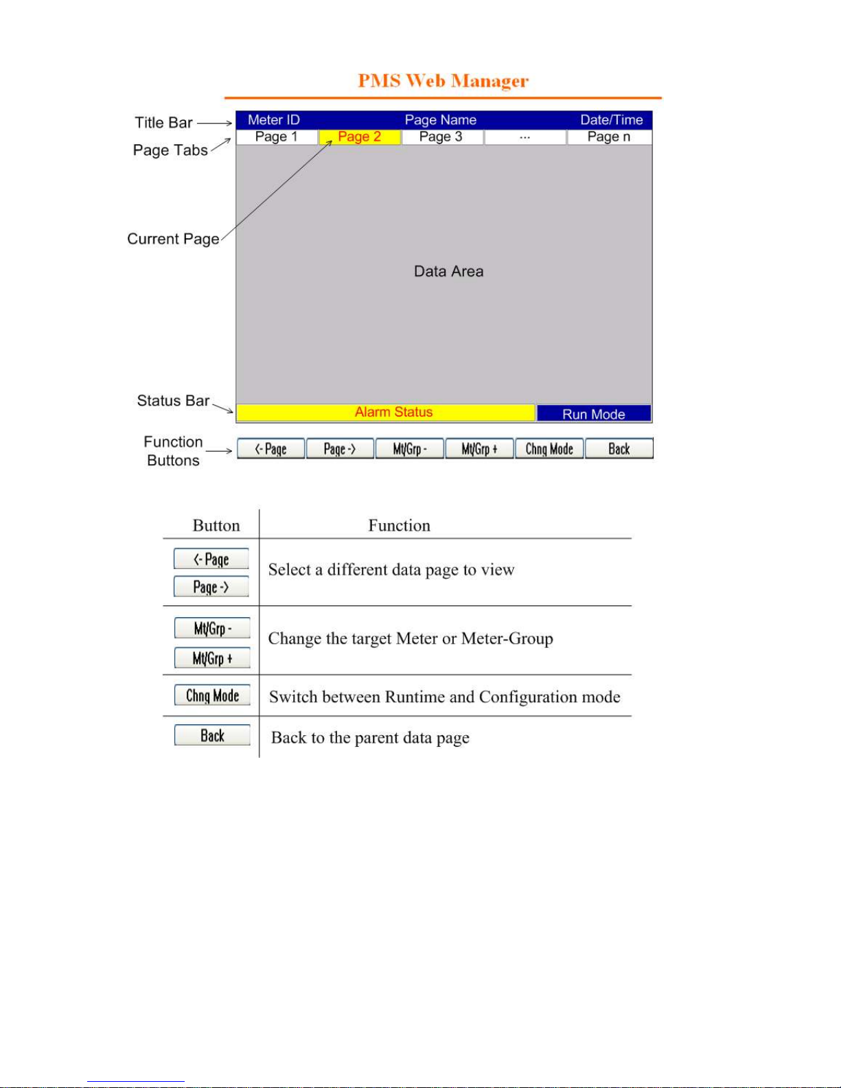
4.1.3 Operating through Web Client
Run the web manager program, and clicking its software function buttons, by
using the cursor directly on the selected item and click.
Page 19
19
In order to use PC as a web client to access PM1600, TCP/IP setting must be
completed first. Please see page 48, TCP/IP setting. (chapter 6.1.5)
Page 20
20
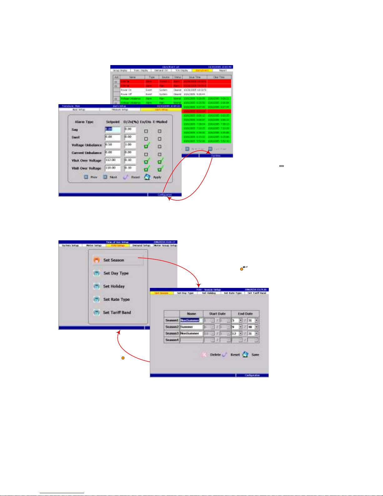
4.2 General Operations
Change the operation mode between Runtime and Configuration
Menu navigation
Press the
Mode
key
to switch between the
Runtime mode and the
Configuration mode.
Run CFG
Press the
Esc
key
to back to the parent
menu.
ESC
Select the desired function and press
the Enter key to perform
Page 21
21
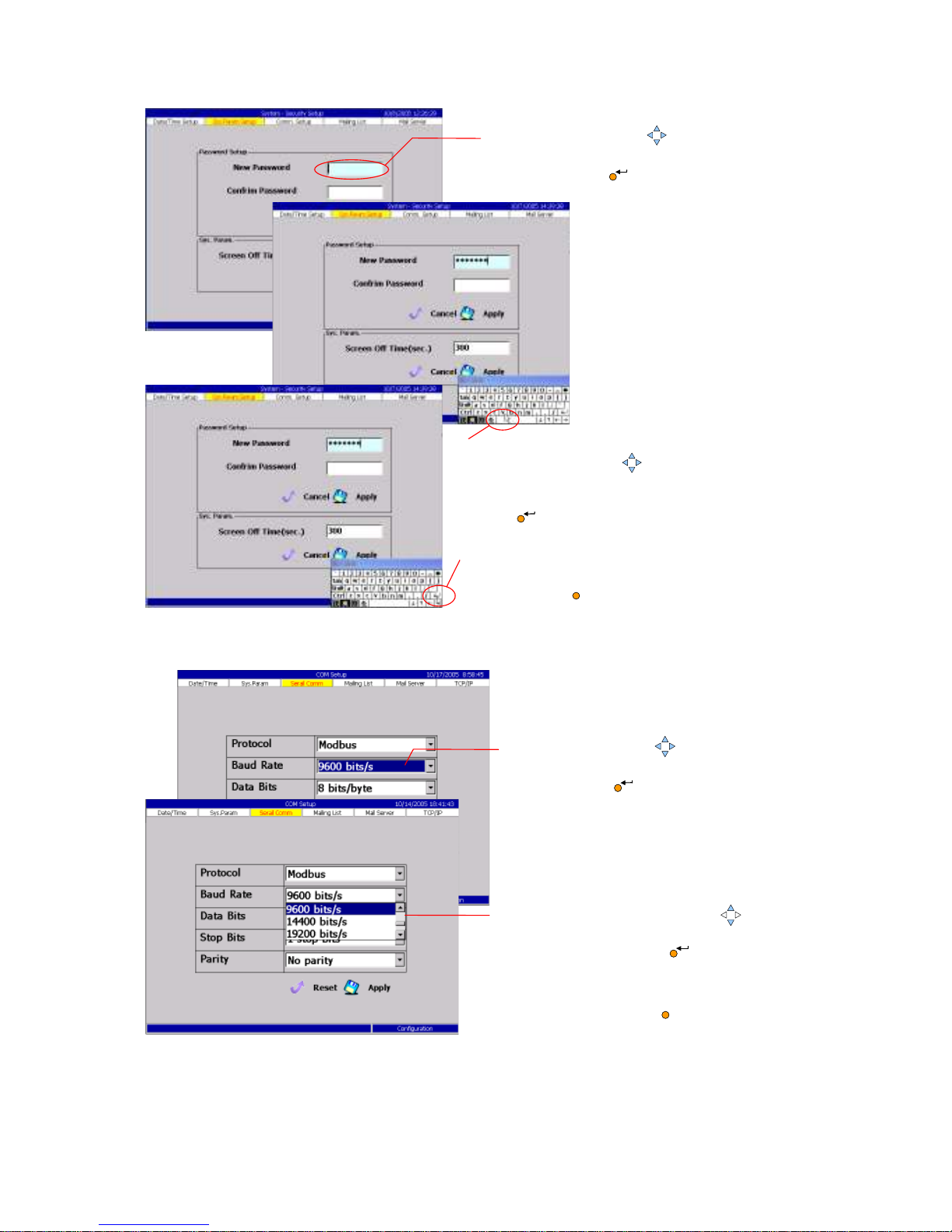
Textual fields with screen keyboard
Selectable drop-down boxes
ESC
1. Use the
Arrow
key to locate
the desired textual field and press
the Enter key to begin editing.
2. While the
screen keyboard
appears,
use the Arrow key to move the
mouse cursor, hover it above the
letter you want, then press the Enter
key to type it.
3. To finish typing, type the
enter
key
on the screen keyboard
, or press
the Esc key to abort.
ESC
1. Use the
Arrow
key to locate
the desired combo box and press
the Enter key to begin editing.
2. Press the up/down
Arrow
key
to scroll the drop down box and
press the Enter key to
choose a value.
Or press the Esc key to a
bort.
Page 22
22
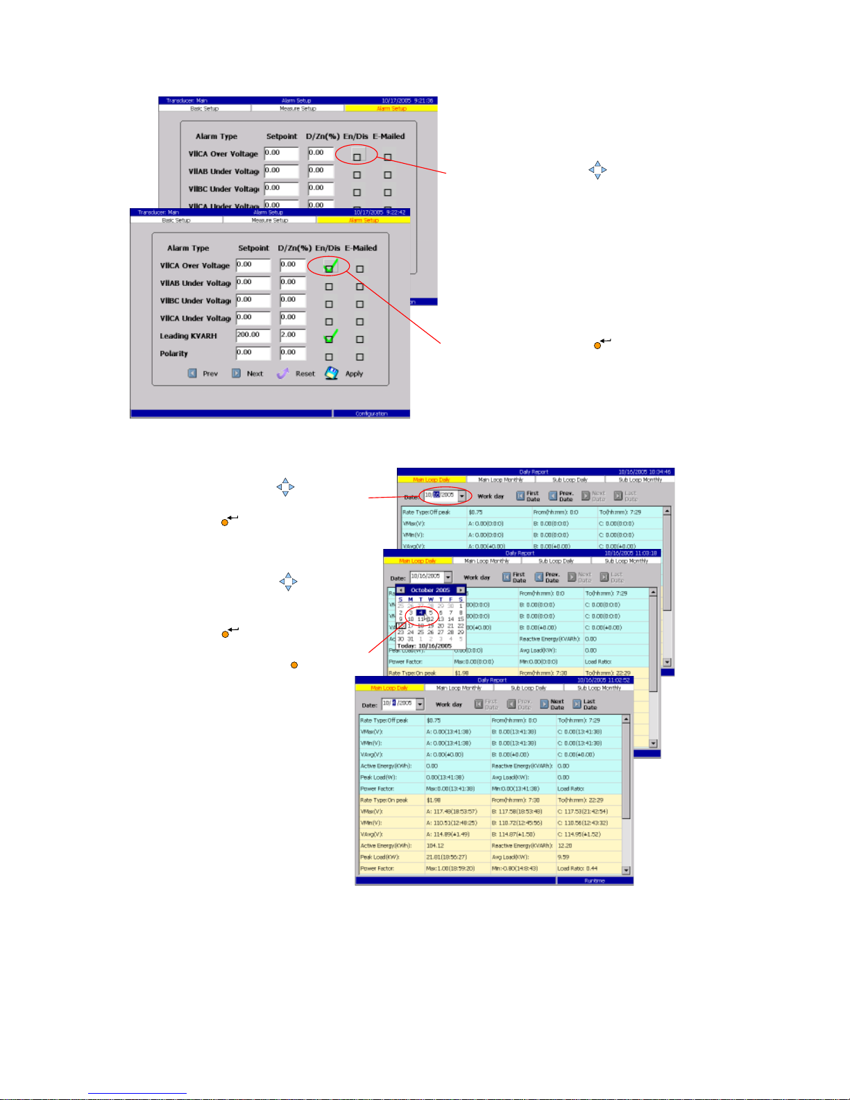
Toggled check boxes
Time picker fields
.
1. Use the
Arrow
key to
locate the desired check box.
2. Press the
Enter
key to
toggle select the check box.
ESC
2. While the
calendar box
appears,
use the Arrow key to move
the mouse cursor, hover it above
the date you want, then press the
Enter key to select.
Or press the Esc key to a
bort.
1. Use the
Arrow
key to locate
the time picker field and press the
Enter key to begin editing.
Page 23
23
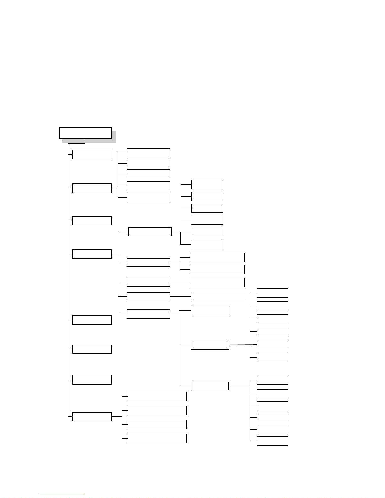
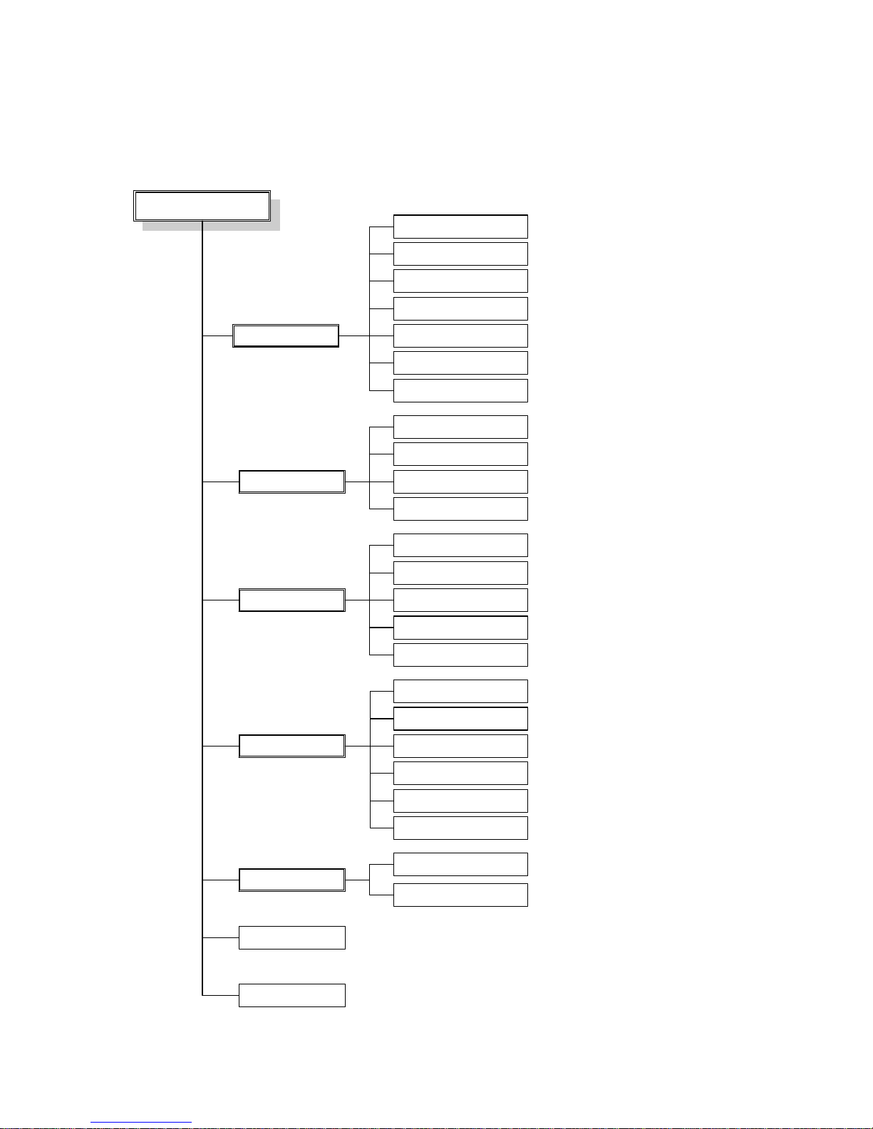
4.3 Function Trees
PM1600 has Runtime and Configuration two kind of operation model, and
provide Run/Config. key to switch it:
4.3.1 Runtime Mode
Runtime mode displays the meter real-time reading, demand control, alarm,
and event report.
Bar Chart Current
Bar Chart KiloWatt
Bar Chart Voltage
Bar Chart Po wer Factor
Digital Display
Current
KW
Voltage
Total Harmonic
V.I.PF
S um ma ry
Realtime Tre nd
Gra phic Disp la y
Digita l Dis pla y
Historica l Tre nd
Ru n Mode
System Overview
Group Dis pla y
Mete r Dis pla y
Demand Control
KWH
Electricity Values
Energy and Demand
Realtime Trend Display
Historical Trend Display
Phasor
Homonic Profile
Bar Chart
Va
TOU
Alarm/Event
Repo rt
Aggregate Daily Report
Aggregate Monthly Report
Sub-Meter Daily Report
Sub-Meter Monthly Report
Vb
Vc
Ia
Ib
Ic
Voltage
Voltage THD
Current
Current THD
KW
PF
Relay
Page 24
24
4.3.2 Configuration Mode
Configuration mode is used to set-up the system parameters, metering
parameters, TOU and demand control parameters.
Con figu ra tion Mode
Sys te m S e tu p
Mete r Se tup
TOU S e tu p
De ma nd Setup
Group Setup
Data Backup
Date/Time Adjust
Serial Communication
Mailing List
Mail Server
TCP/IP
Password Modification
Basic Setup
Measure Setup
Alarm Setup
Trend Setup
Set Season
Set Date Type
Set Holiday
Set Rate Type
Set Tariff Band
Parameter Setup
IO Setup
Sch e du le Se tu p
Set Season
Set Date Type
Set Holiday
Set Special Day
Set Day Plan
Calendar
User’s Data
Page 25

25
4.4 Connecting the PM1600 with client PC
For using client PC to configure PM1600 and to monitor the PM1600,
connection between PM1600 and client PC has to be established first. Basically,
the communication goes through TCP/IP. Two ways of connection are described
in the following section.
4.4.1 Pier to pier connection
1. Connect PM1600 with PC by a pier to pier Ethernet cable. (Cross over cable)
2. On PM1600 side using hard keys or USB mouse, change to configuration
mode and setting TCP/IP as IP:192.168.2.240, Mask:255.255.255.0 (refer
to TCP/IP setting in chapter 6)
3. On PC side, setting IP address to 192.168.2.245, Mask to 255.255.255.0, and
leave gat way and DNS blank.
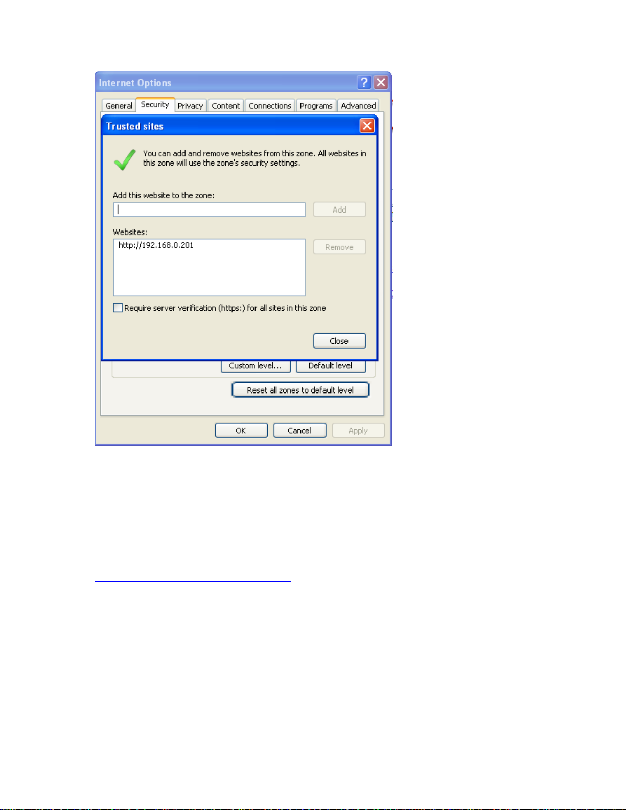
4. Setting trusted site for PM1600 by including 192.168.2.240 in the trusted
site group. (start browser → Tools → Internet option → Security → Trusted
site → site → Add then type in 192.168.2.240 → uncheck the “ require sever
verification for all sites in this zone”).
4.4.2 Network Connection
In this section you will need assistance for MIS department or your internet
system providers to set up the connection.
1. Connect PM1600 with PC using LAN Ethernet cable.
2. On PM1600 side, power on PM1600 and switch to configuration mode the
default user’s names is “admin” and password is “admin”. Obtain TCPIP
address, Mask and gat way from MIS or system providers, enter those data to
PM1600(as described in chapter 6). Leave DNS blank for future use.
3. On PC side, include the PM1600 address into your PC trusted site.
If you experience the difficulty of communication due to the block ActiveX
controls, then you should change some default of ActiveX controls and plug-ins
setting by:
1. Brower → tools → internet option → security → trusted sites → custom level
→ download signed ActiveX controls → enable.
2. Brower → tools → internet option → security → trusted sites → custom level
→ indulge and script ActiveX controls not marked as safe for scripting →
prompt.
Page 26
26
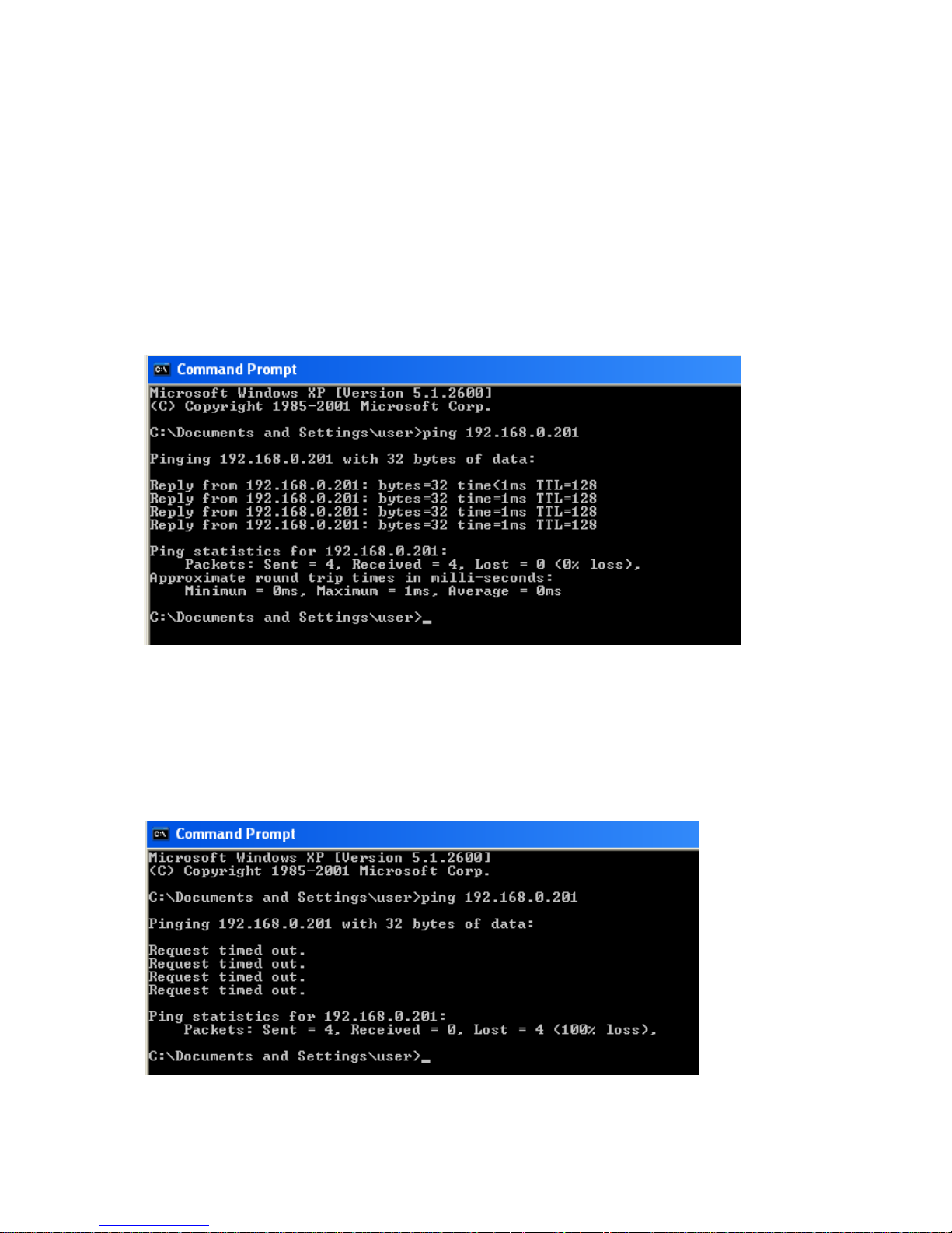
How to run web server
First use Ping instruction at the DOS prompt and make sure that
communication is established properly between PC and PM1600 unit.
Format: Ping IP address of PM1600
Ex: Ping 192.168.0.201
If the communication is proper, then it shows reply as follows..
If communication is not proper, then it will show the reply as follows..
In this case, you need to set TCP/IP settings in both PC and PM1600. Please
note that you should use proper cable and it should be connected at the label
shown as “LAN2” at the PM1600
Page 27
27
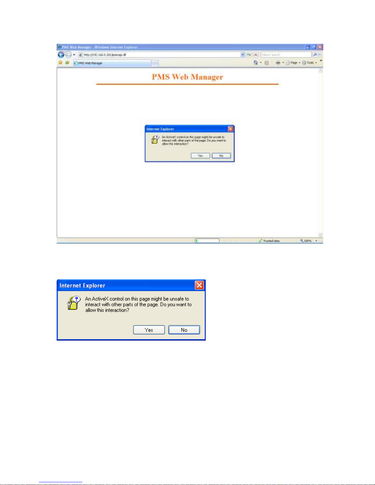
In the browser, you need to enter the following
Format:
http://IP address of PM1600/ipmisapi.dll
Ex: Assume IP address of PM1600 is 192.168.0.201, then
http://192.168.0.201/ipmisapi.dll
Page 28
28
Click on Yes, when prompted as above.
Page 29
29
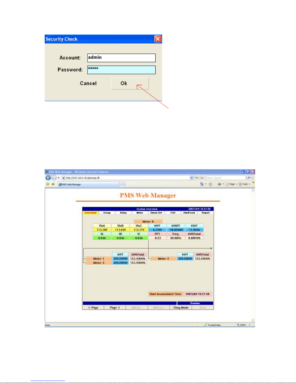
User name: admin
Password: admin
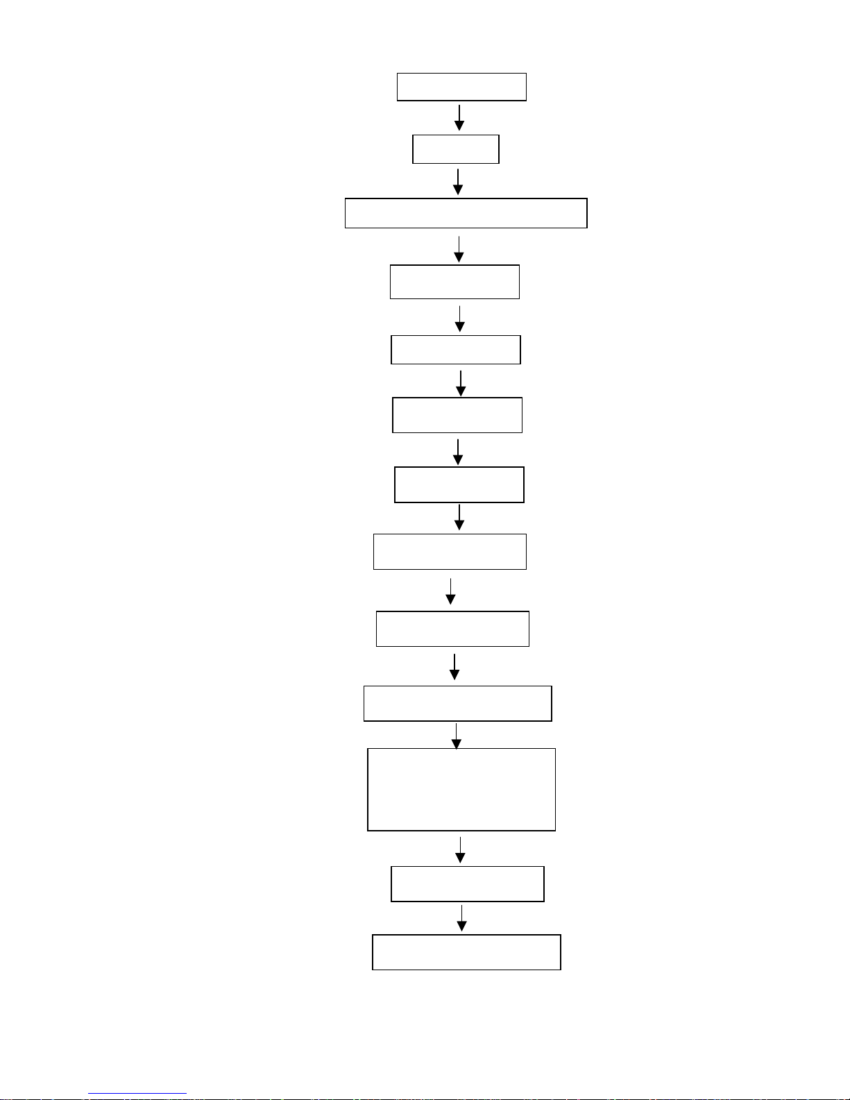
Now click on “OK”, please do not enter on the keyboard, use mouse and then
click on OK. If every thing is proper, then u should able to see data updating in
the PC as follows..
Page 30
30
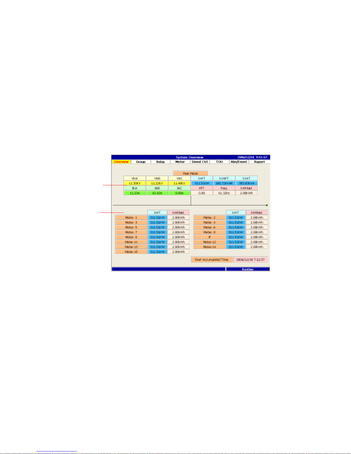
4.5 Setting the PM1600
Wire and install
Demand Setting
TCPIP setting
Mail sever setting
Mail list established
Scheduling control
User’s management
Schedule setting
Meter Group Setting
TOU Setting
Meter set up
E-mail event and report
Switch to configuration mode
Power on
System setup
**** If needed
**** If needed
**** If needed
**** If needed
**** If needed
**** If needed
**** If needed
Page 31
31
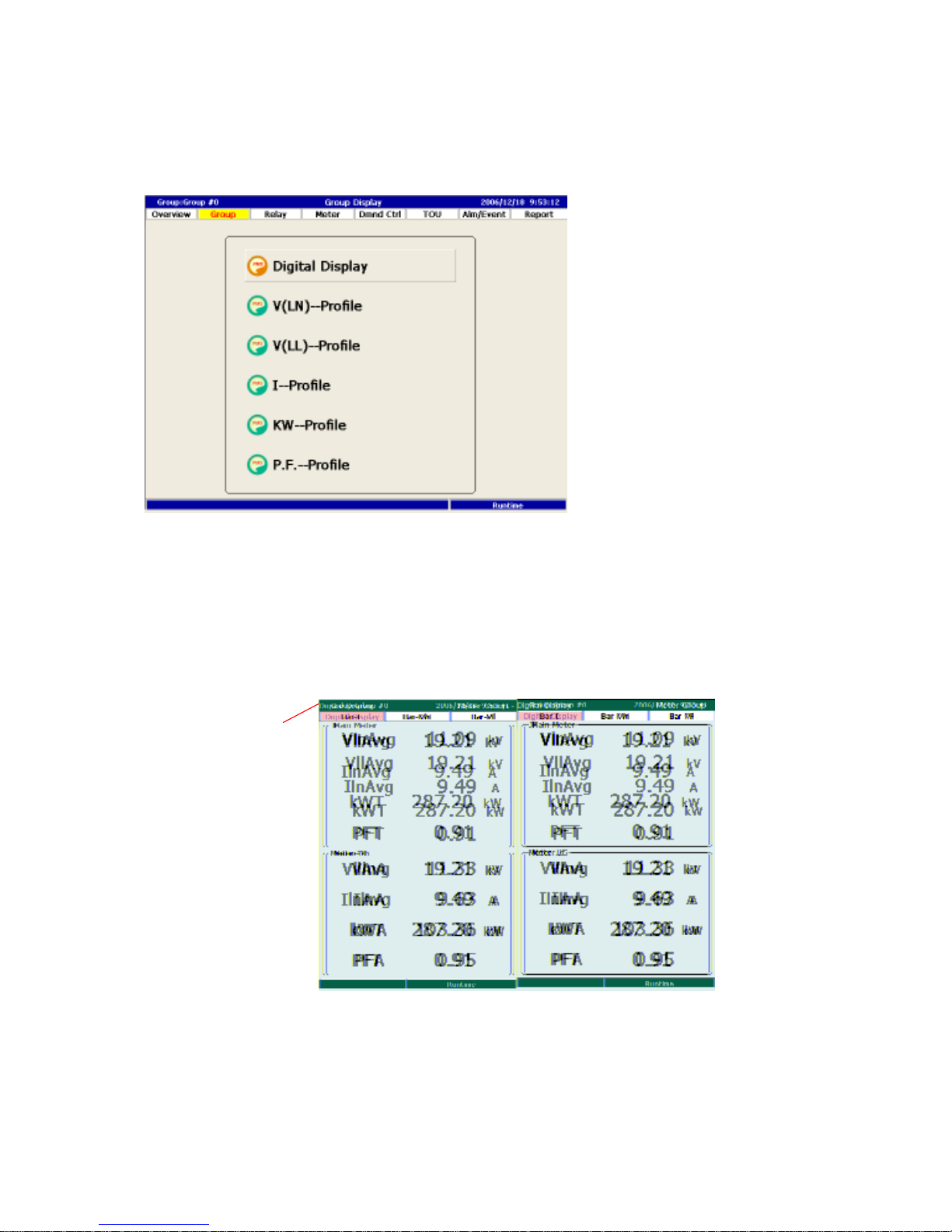
1. Main meter
2.
Sub meter
Chapter 5 Run Mode
This chapter describes the complete functions of PM1600. Please first refer to
the function tree chart to get familiar with PM1600 systematically. This will help
you to use the powerful PM1600 quickly and properly.
5.1 System Overview
System overview is the designated root page when PM1600 is powered. In this
page, the detail real time data of the main meter will be shown on the top part as
well the brief data of all sub meters. The main meter is the meter that is selected
as the target meter demand control.
1. Main Meter:Display detail real time power value of main meter.
2. Sub Meter:Display real time power and energy value of each sub meter.
Page 32
32
1. Group Name
5.2 Meter Group or Meter Display
According to the group configuration setting, real time power value of each
group of meter is displayed here in digital form or bar chart.
5.2.1 Digital Display
Display for up to 4 meters as a group, including real time Voltage, Current,
Power, Power Factor in digital form.
Use METER/GROUP key to switch to next or previous meter group.
Page 33
33
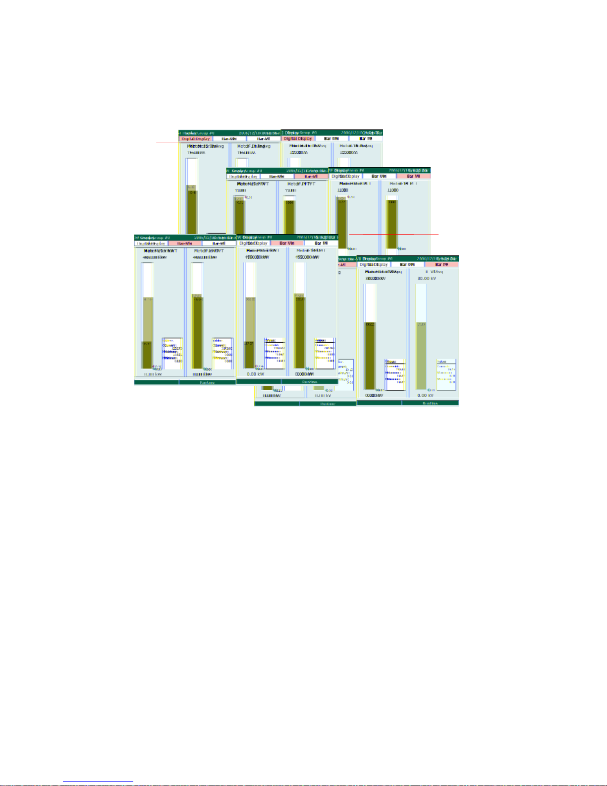
1. Max/Min
2. Group
Name
5.2.2 Bar Chart Display
This page display real time Voltage, Current, Power, Power Factor in bar- charts
from your each meter group.
1. Max/Min current:Display each power max. and min. current of this day
value.
2. If the meter does not return max and min values, PM1600 will show 0.
Page 34
34
5.3 Relay Status
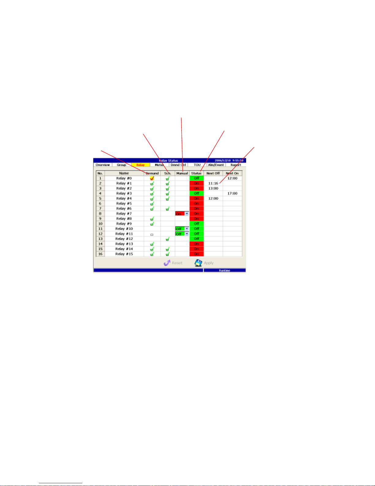
This page shows the status of all the controllable relays. The status of relays can
be controlled by the demand control, schedule control or manual control. You
can use the check box to over right the status by checked the check box or use
the manual button to change.
1. The “checked” check box enables or disables the relay triggered by the
demand controller.
2. The “checked” check box enables or disables the relay triggered by the
scheduler.
3. Turn the relay on/off manually, so that both the demand trigger and the
schedule trigger are disabled simultaneously.
4. Show the current relay output status.
5. Show the information about the next schedule plan adopted from the
scheduler.
2.
Schedule Trigger
1.
Demand Trigger
3. Manual control
4. Relay Status
5. Next Operation
Page 35
35
1. Meter Name
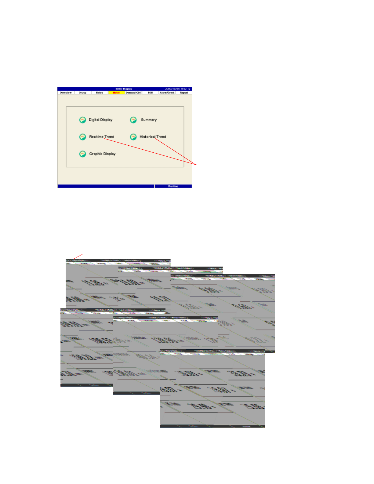
5.4 Individual Meter Display
According to how the meter was configured, each meter will display its real time
and historical power value in digital and graphic form. (see chapter 6.2.4
Trend/Data Recording)
5.4.1 Digital Display
This section displays real time values of voltage, currents, power factor energy,
THD for each meter. Some meters may show different data set depend on wiring
mode of meter.
Push Meter TRANSD/GROUP button to switch to different meter.
1. Trend Display
Page 36
36
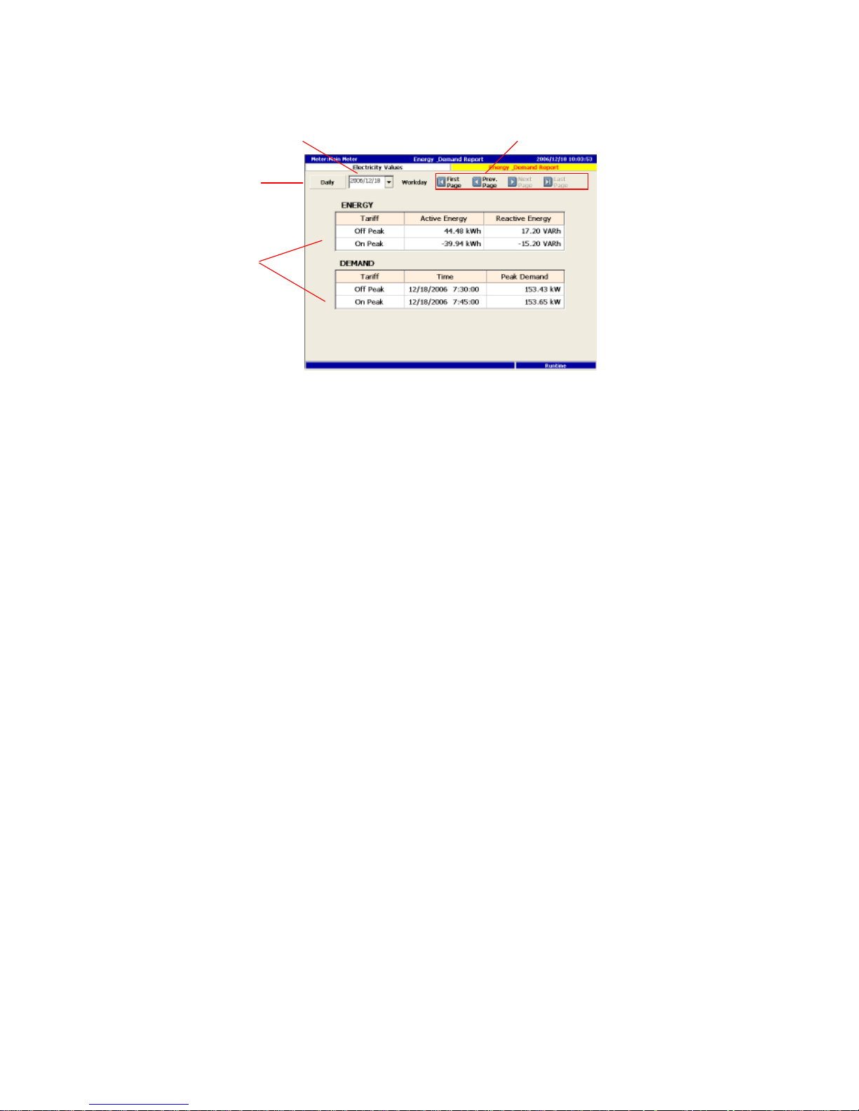
5.4.2 Summary Display
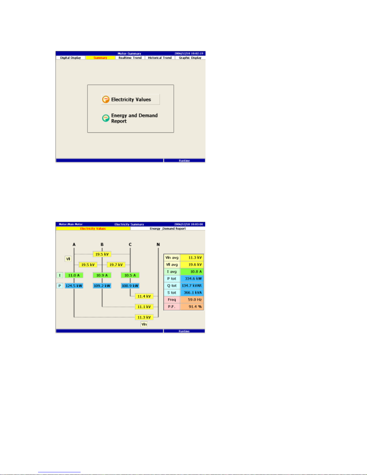
Summary display graphically shows the real time power value for each meter. It
also provides the summary information of energy and peak demand for various
tariff band. This will also be seen in report section.
Electricity Values
Page 37
37
Demand & Energy
1. Switch to daily or monthly data display.
2. Select date and month.
3. Based on current page, select different time zone accordingly.
4. Based on the TOU rate setting, show the total values of energy, and peak
demand.
1. Daily / Monthly
2. Date / Month
4. Demand Rate
3. Date/Month Navigation
Page 38
38
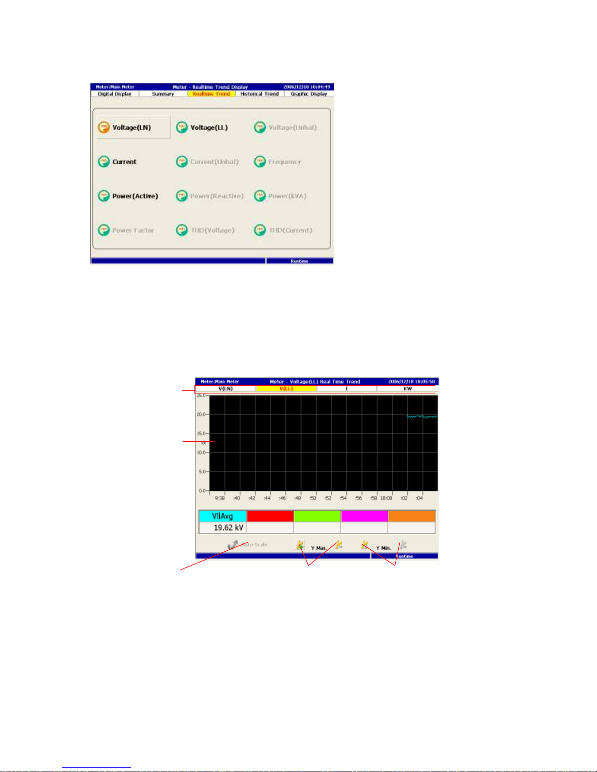
5.4.3 Real time Trend
PM1600 can display various power values including voltage, current, power
factor…etc. alone the time for each meter. The displayed item for each meter is
varied according to the setting in the configuration mode(see chapter 6.2.4).
Auto scale is the default for trend display. User can modify Y-axis scale by using
Y maximum and minimum button.
1. Measure type indicates all the display items for this meter.
2. Display area for real time data.
3. PM1600will automatically assigns the proper Y-scale if auto-scale button is
clicked.
4. Two buttons are provided for users to adjust the Y-maximum of Y-axis.
2. Display Area
3. Auto/Manual 4. Y-Max Adj.
5. Y-Min Adj.
1. Measure Type
Page 39
39
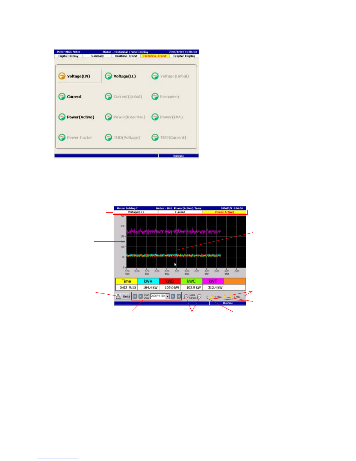
5.4.4 Historical Trend
Similar to real time trend, PM1600 can display various power data for each
meter. The display items are the same as real time trend which are pre
determined in the configuration mode for each meter.
1. Meter type indicates all the display items for this meter.
2. Display area for historical trend.
4. Date selection button.
5. Time scale(x-axis)adjust button to increase or decrease the time span.
6. Y-scale auto scale button.
7.8. Y-axis adjust button to modify the maximum and or minimum.
2. Y-Scale
4. Date Navigation 5. Time-Scale Adj.
8. Y-Min Adj.
1. Measure Type
7. Y-Max Adj.
6. Auto/Manual
3.
Detail View
9.
Light Bar
Page 40
40
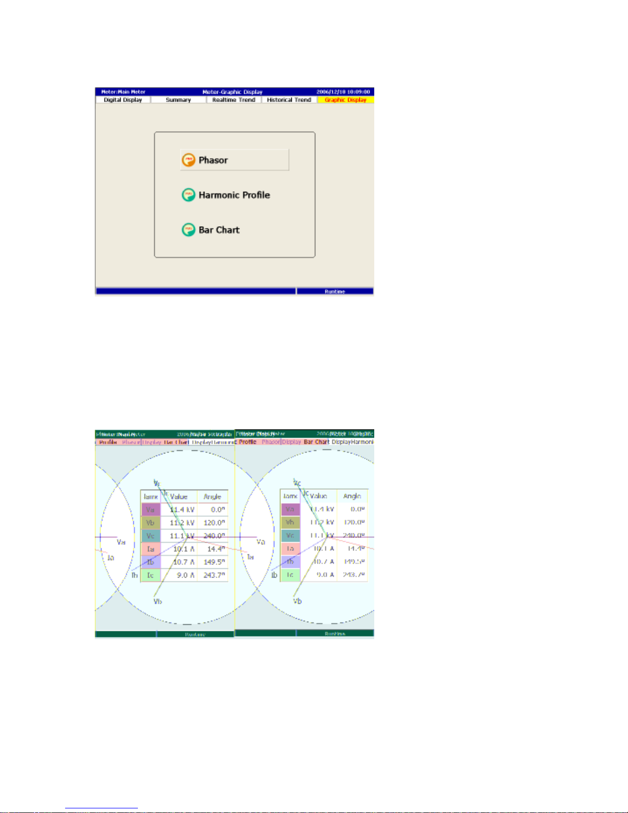
5.4.5 Graphical Display
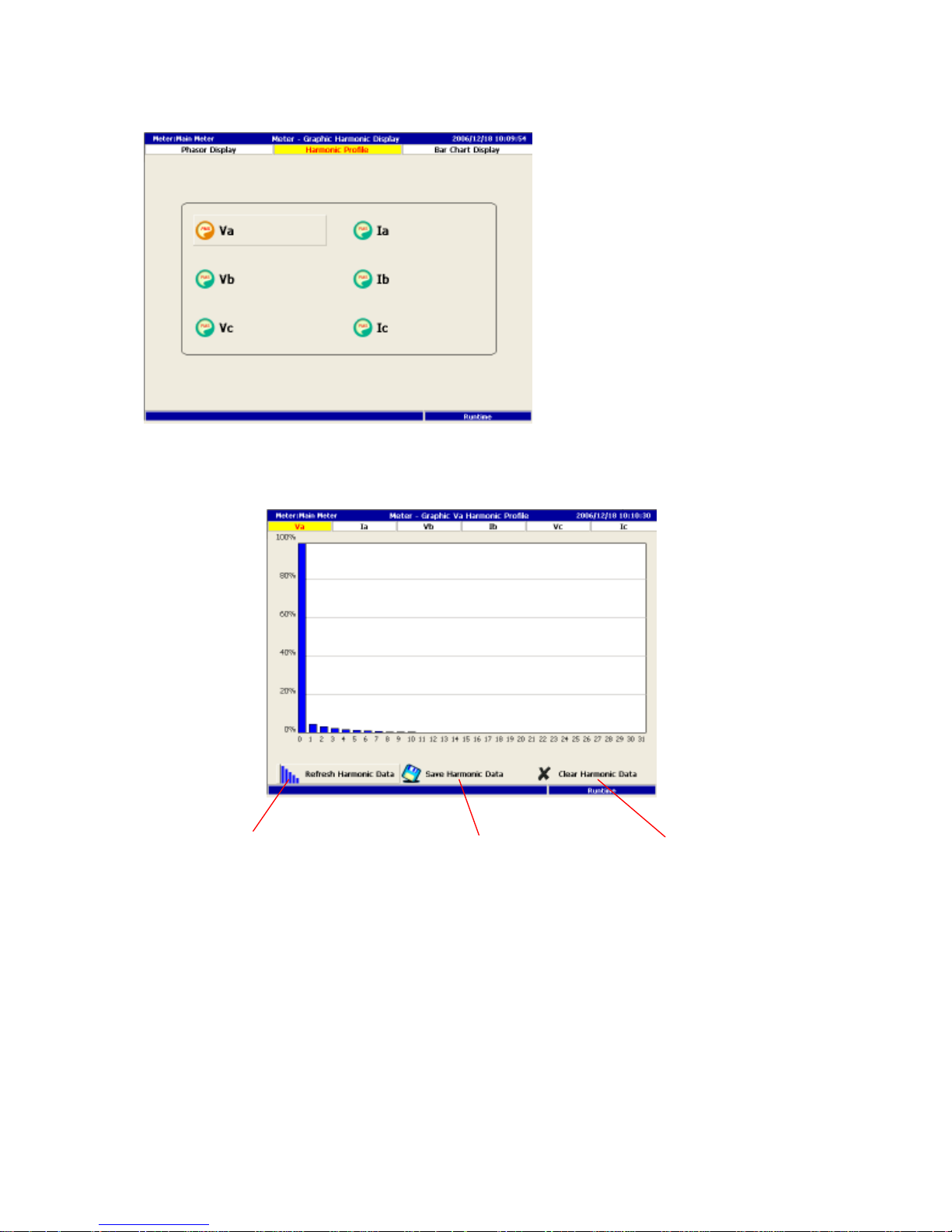
PM1600 provides three graphic displays for each meter phasor display,
harmonic profile and bar chart. Some meter may not have phasor display or
harmonic data because the wiring mode or meter itself does not measure
harmonic profile.
Phasor
Display each of meter, three phase by axis, and current value.
Page 41
41
Harmonic Profile
Display each of the meter three phase voltage and current by harmonic
distribution graphic.
1. PM1600 will trace the latest harmonic reading every 30 seconds. Do not click
the refresh button during reading while the button display “waiting for data”.
2. Save the harmonic data to the area assigned by users.
3. Clear the current display date.
1. Wait Status / Refresh 2. Save Profile 3. Clear Profile
Page 42
42
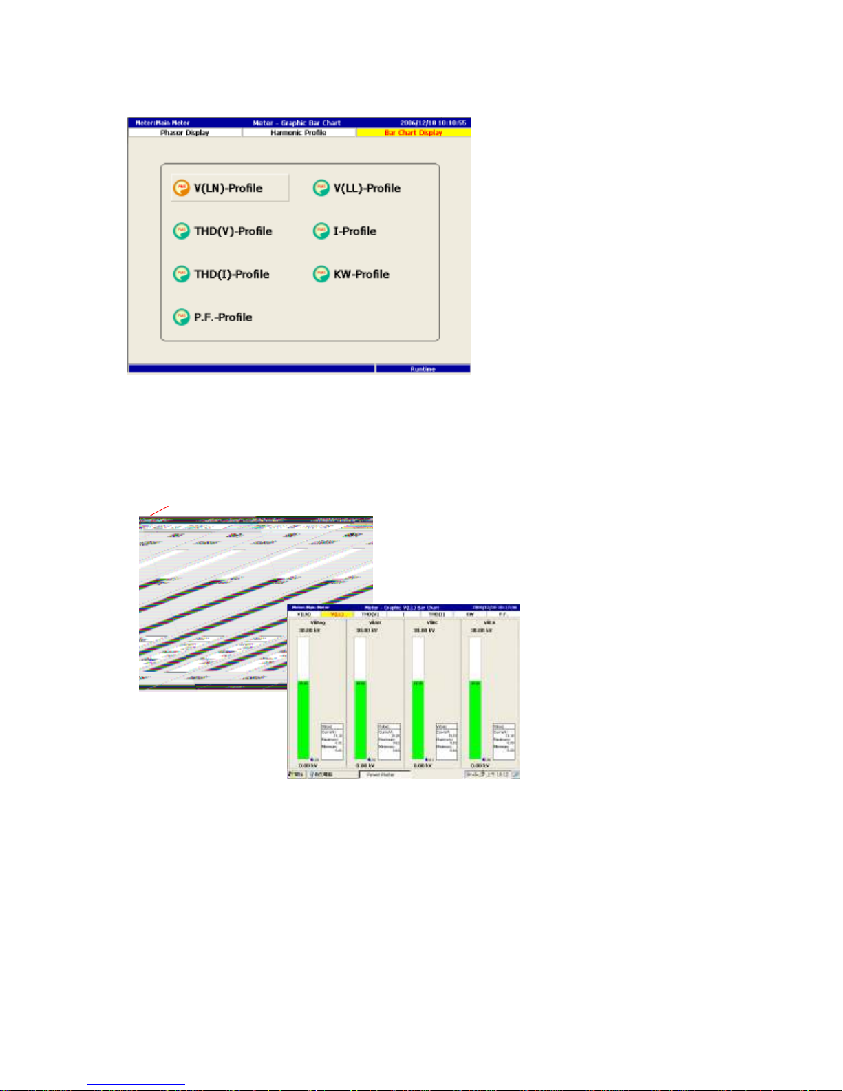
Bar Chart Display
This section shows Voltage, Current, Power, Power Factor, Voltage THD,
Current THD in bar chart form for each meter similar to group display in
previous section.
1. Push METER/GROUP buttons to switch to different meter.
1. Meter Name
Page 43
43
5.5 Demand Control
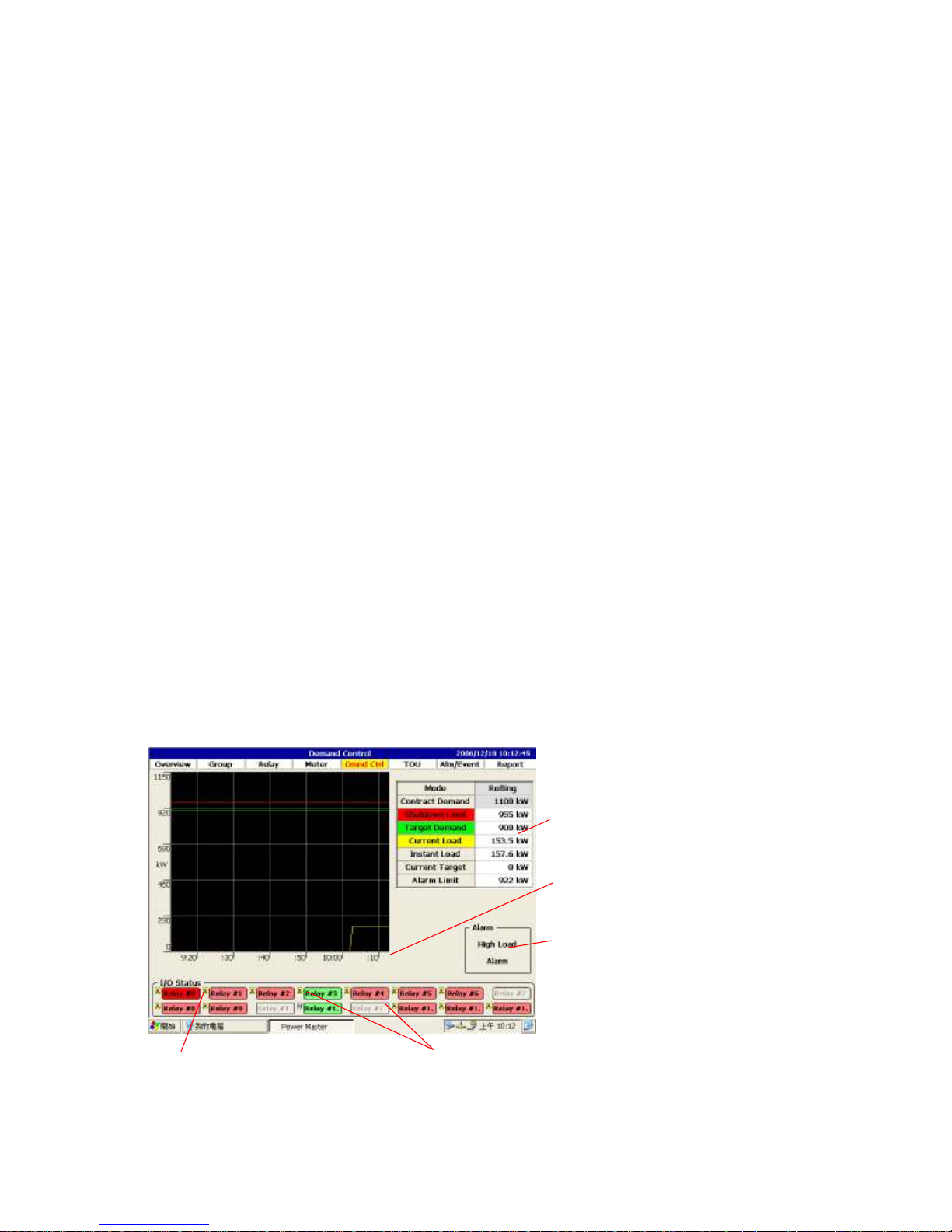
In this section, PM1600 demonstrate the demand control with two calculation
algorithm: blacking and rolling.
5.5.1 Blocking mode
When the blocking mode was selected, PM1600 will follow the demand
parameters, such as target demand,… etc., to carry out demand control. All
these parameters are pre-entered in the configuration mode.
The red line shows the shutdown limit curer which means the relays will be
triggered to off status when ever the predict demand line exceed the shutdown
limit line during 15 minutes window. In the mean time the high load alarm box
will be turned to red.
As the end of predict demand line(light blue color)exceed the alarm limit, the
alarm check box will turn from green to red.
PM1600 also allow the operator to change the I/O status in this page by
selecting the relay and click the enter key. There are three choice:Manual off,
Manual on and automatic by demand control. The small letter by each I/O
shows “M” or “A” accordingly.
In I/O status, green color stands for “off status”, and red color stands for “on
status”.
2. Demand Interval
1. Demand Parameters
4.
Load Status
5. Shedding Options
3. Alarm Status
Page 44
44
1. Show the set up value of demand control parameter and real time value of
related demand.
2. Shutdown Limit: shedding demand value, and will start shedding upon over
load, as show in red line.
3. Target Demand: target demand value, as show in green line.
4. Current Demand: current demand value, as show in yellow line.
5. Predict Demand: predict demand value, as show in blue line.
6. User set up the demand time interval. This will be used as the time axis range,
to display the latest demand data.
5.5.2 Rolling mode
Using the 1 hours axis to show the rolling demand calculation mode for the
demand change.
In this figure, the green line shows the target demand. The yellow line is current
load. The red line stand for the shutdown line to triggered the IO to shed the
demand and the high load alarm will be changed to red color, when ever the
yellow line goes above.
When current load exceed the alarm limit, the alarm box will be turned to read.
All the designated IO relays which will be controlled by demand are listed in IO
status area. Red color means on status and green means off status. Since the IO
relay will be controlled by demand automatically, a small “A” will display by the
relay. PM1600 will allow users to change the relay status in this page, the small
letter there will be signed as “M”.
Page 45
45
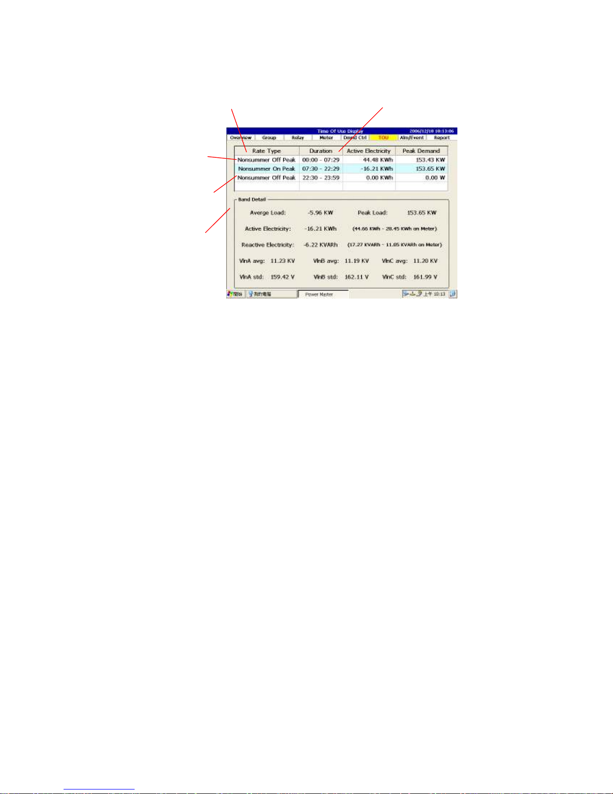
5.6 Time of Use
1. This column shows rates type in one day.
2. This column shows time duration of each rate type.
3. The current rate band will be displayed with the light blue colored
background and show all the detailed in the Band Detail Area.
4.5. Move the highlight to examine the band detail for different rate band.
5. Rate Band Detail
1. Demand Rate
2. Rate Band
4. Target Rate Band
3.
Current Rate Band
Page 46
46
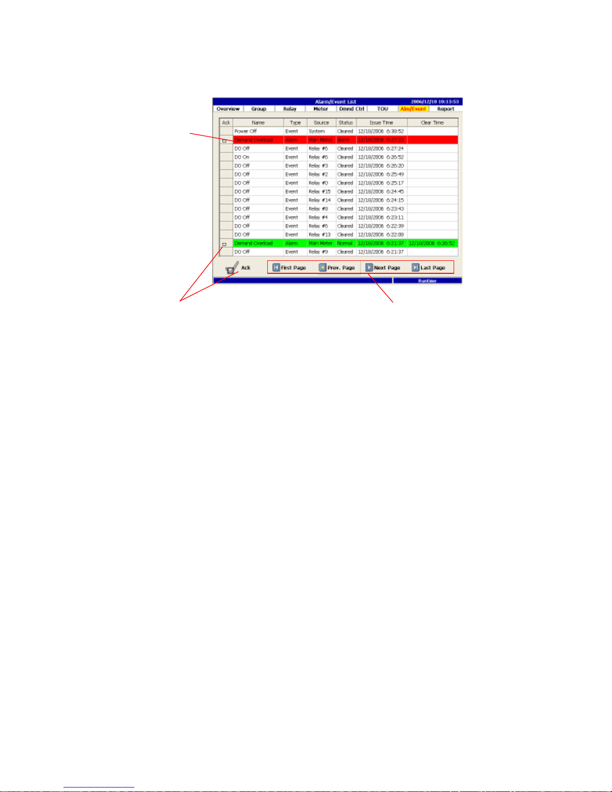
5.7 Alarm/Event Log
1. The red background will express after the Alarm occurred, and will turn to
green color after the status back to normal.
2. Press the acknowledge button, to acknowledge of that page message of
alarm/event.
3. Forward or backward, to bourse Alarm/Event message.
3. Page Navigation
2.
Acknowledgement
1.
Alarm / Event
Page 47
47
5.8 Report
PM1600 provide daily and monthly reports for main meter also for every
submeter.
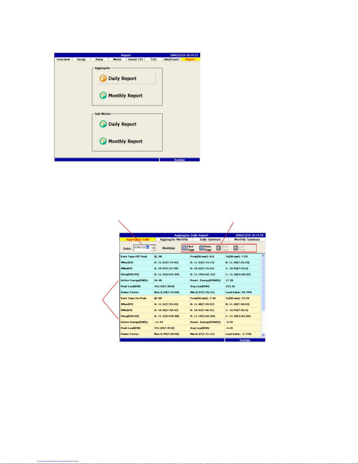
5.8.1 Aggregate Daily Report
1. Select the desired date.
2. Move to previous or next date.
3. Display detail power information for various rate bands separated by various
color background. Please note that the time is displayed as “hh:mm:ss”.
1. Date
3. Rate Band
2. Date Navigation
Page 48
48
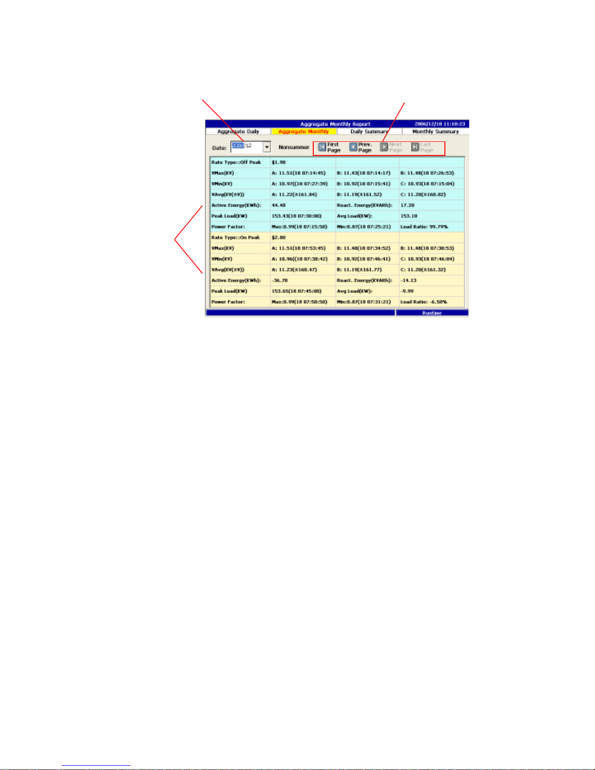
5.8.2 Aggregate Monthly Report
1. Select the desired month.
2. Month navigation.
3. Display detail information for various rate bands separated by different color
background. Please note that the time is displayed as “dd:mm ss” slightly
different from daily report.
3.
Rate Band
1. Month
2. Month Navigation
Page 49
49
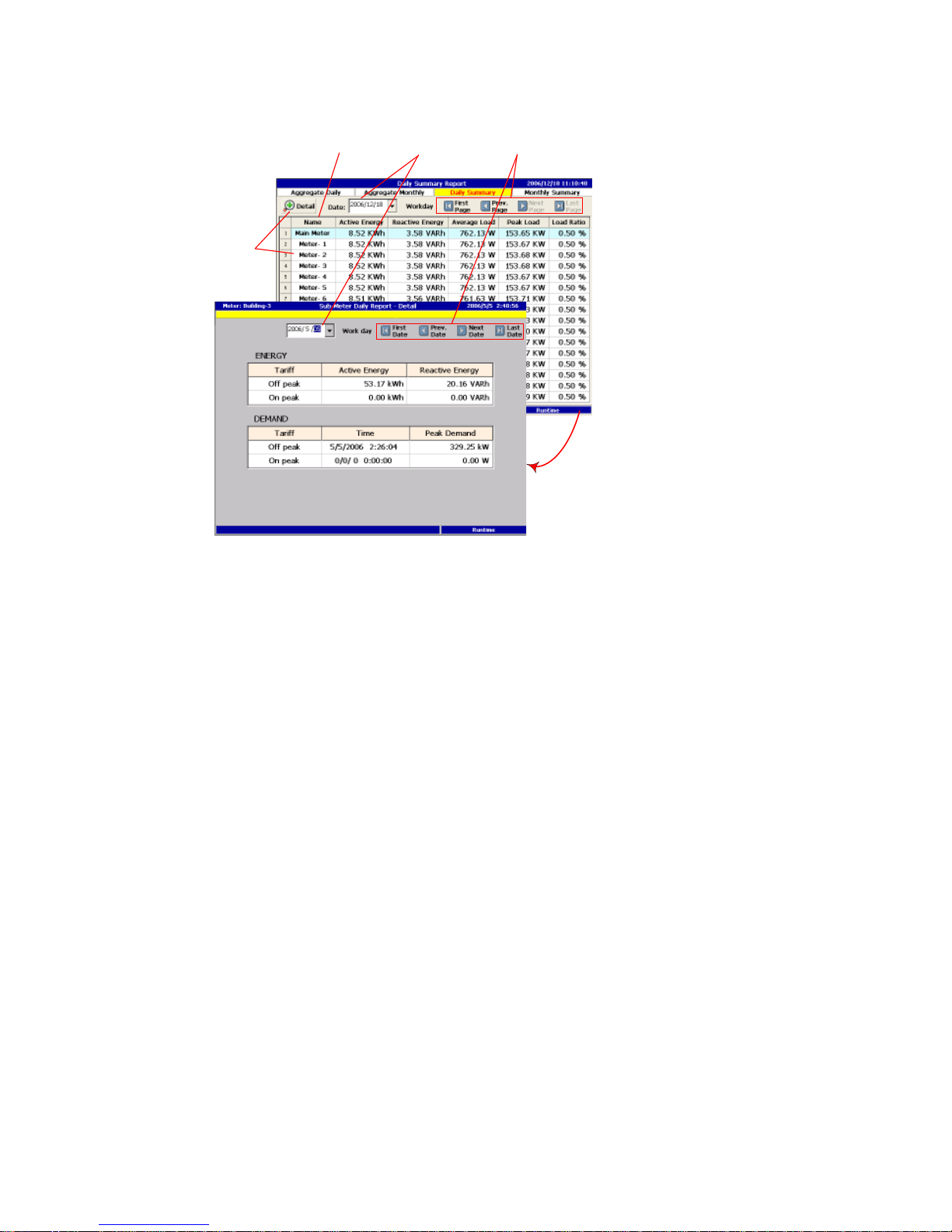
5.8.3 Sub-Meter Daily Report
1. Display all sub meter daily data in a summary form.
2. Date selection.
3. Date navigation.
4. To examine any particular sub meter in detail, select the meter you like and
click the meter detail button.
2.
Date
3. Date Navigation
4. Meter Detail
1.
Meter
Page 50
50
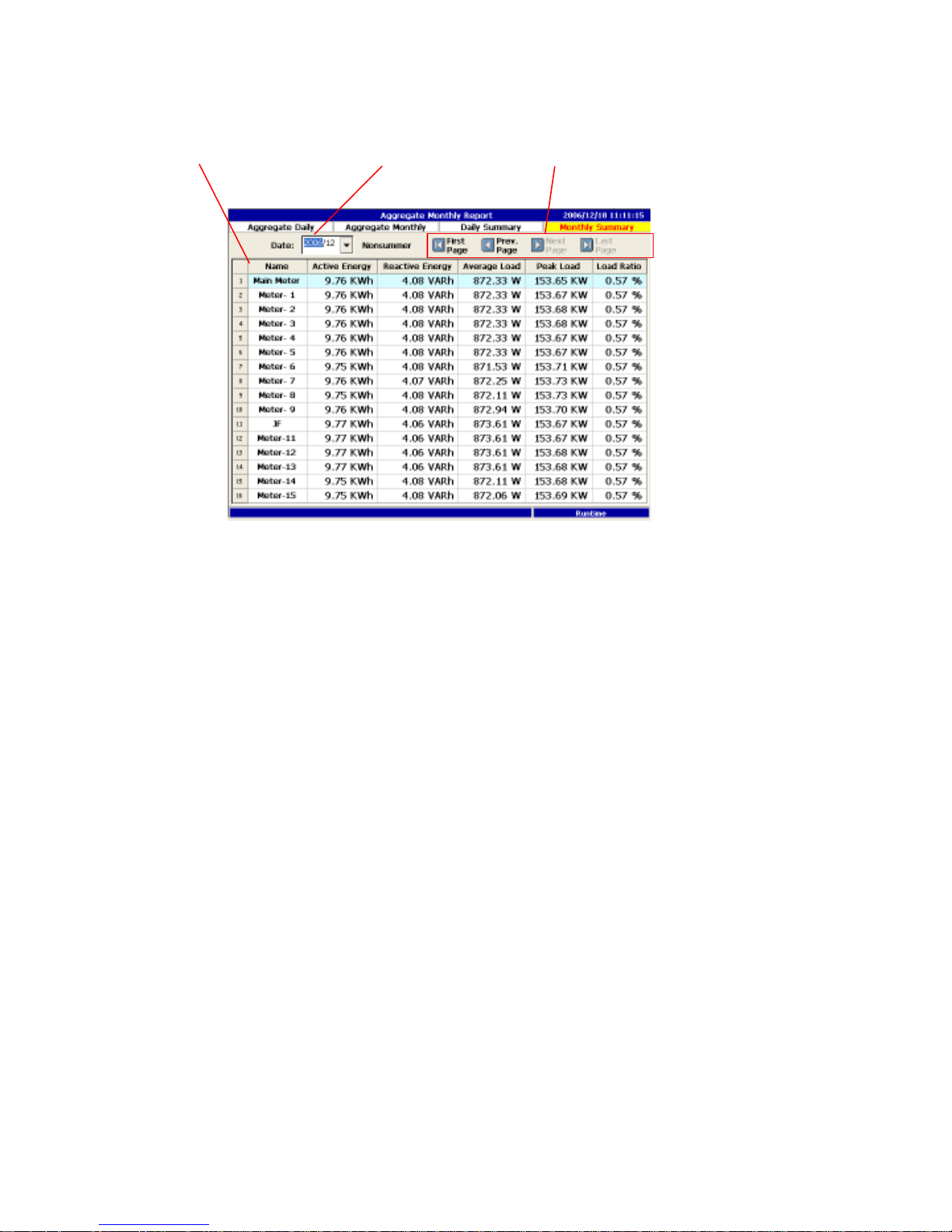
5.8.4 Sub-Meter Monthly Report
1. Display all sub meter monthly data in a summary form.
2. Month selection.
3. Month navigation.
4. To examine any particular sub meter in detail, select the meter you like and
click the meter detail button.
3. Month Navigation
2. Month
1.
Meter
Page 51
51
Chapter 6 Configuration Mode
In order to properly use PM1600 for different application and situation, PM1600
must be configured before use. The detail configuration tree was listed below.
Again, please first refer to the function tree chart, to obtain a systematic idea.
There are seven functions can be set for PM1600, some are required, some are
not. From part one, users can easily distinguish the required from non-required.
The following will give a detail description for each function.
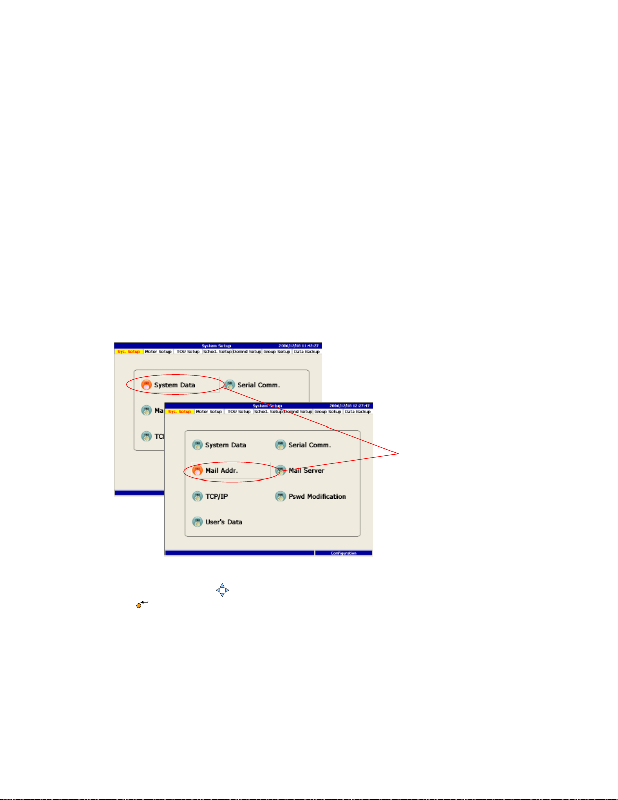
6.1 System Setup
System Setup is the first thing to begin with for setting the system that fulfills
the user’s requirement. It includes data/time setup, communication setup, mail
list setup, mail server setup, TCPICP setup, password modification and user’s
data setup.
1. Use the Arrow key to navigate among the functions, then press the Enter
key to perform.
1.
Page 52
52
2. Press the Page key to switch from the neighbor function.
6.1.1 Date/Time Setup
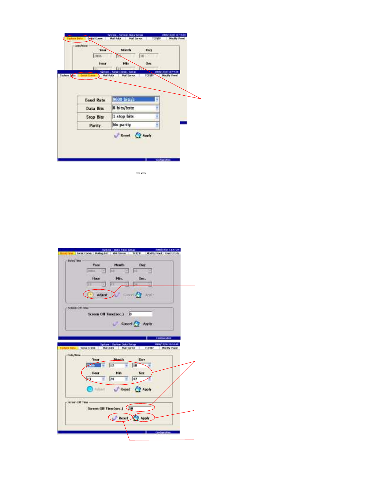
It is important to set the correct data and time for PM1600, because it involves
the schedule control, rate type and also demand control. After entering all the
correct data, click the apply key to finish the change.
2.
2.
3a
.
3b.
1.
Page 53
53
1. Press the Enter key to begin adjusting, or press the Esc key to exit this
dialog.
2. Adjust the system time or the screen off time.
3a. Finally, select the Apply button and press the Enter key to apply the
new value.
3b. Or select the Cancel button and press the Enter key to drop all the
changes.
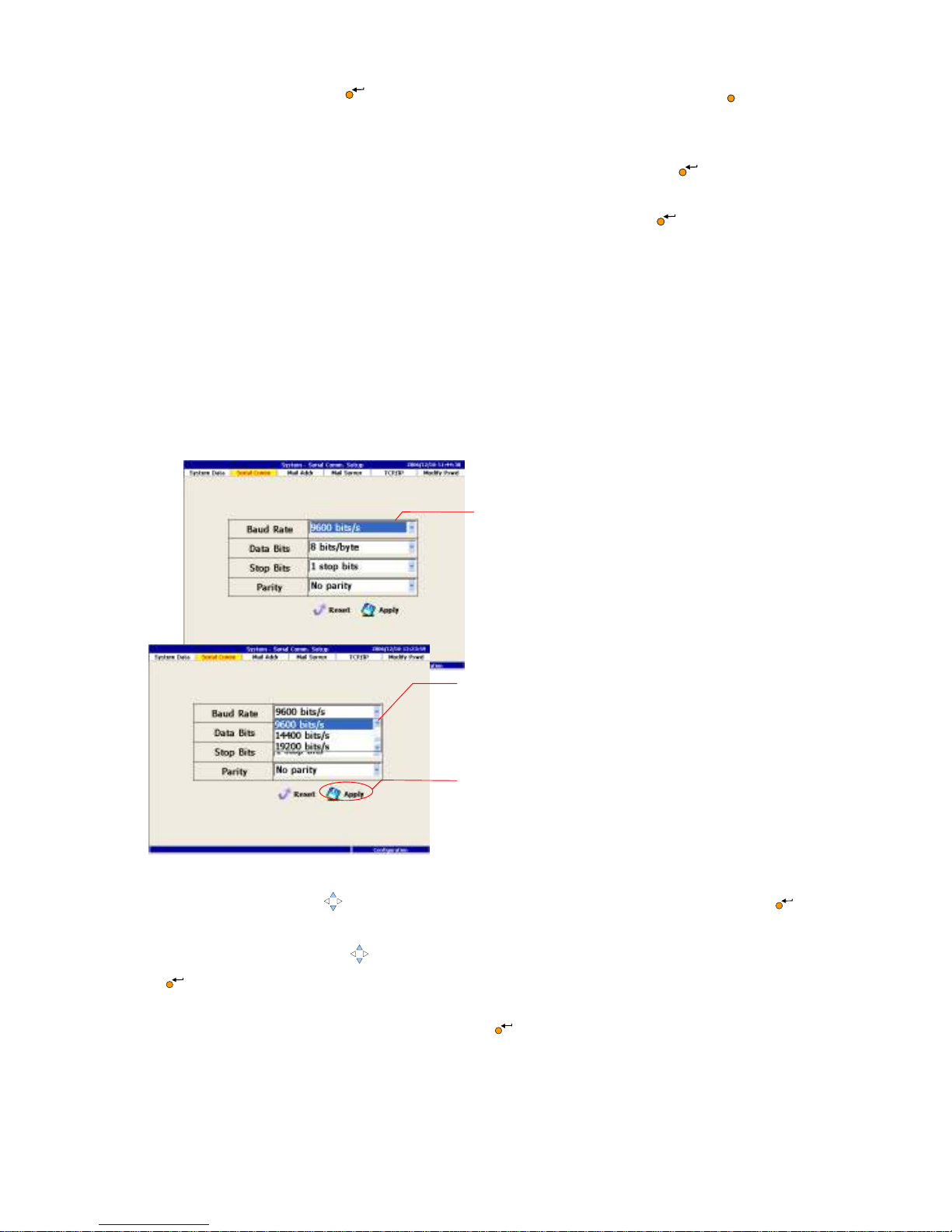
6.1.2 Serial Communication Setup
In order to obtaining data from each meter, PM1600 must be entered the needed
information for each meter. PM1600 requires baud rate, data bits, stop bits and
priority from each meter. The above data should be provided by meter
manufacturer. After entering the proper values, click the apply key. If the data
enter is incorrect, PM1600 will show communication fail in the runtime mode.
1. Use the Arrow key to navigate among the fields. Press the Enter key to
begin editing.
2. Press the Arrow key to scroll the drop down box and press the Enter key
to choose the value.
3. Select the Apply button to apply the new value or the Cancel button to drop
the change, then press the Enter key .
3.
2.
1
ESC
Page 54
54
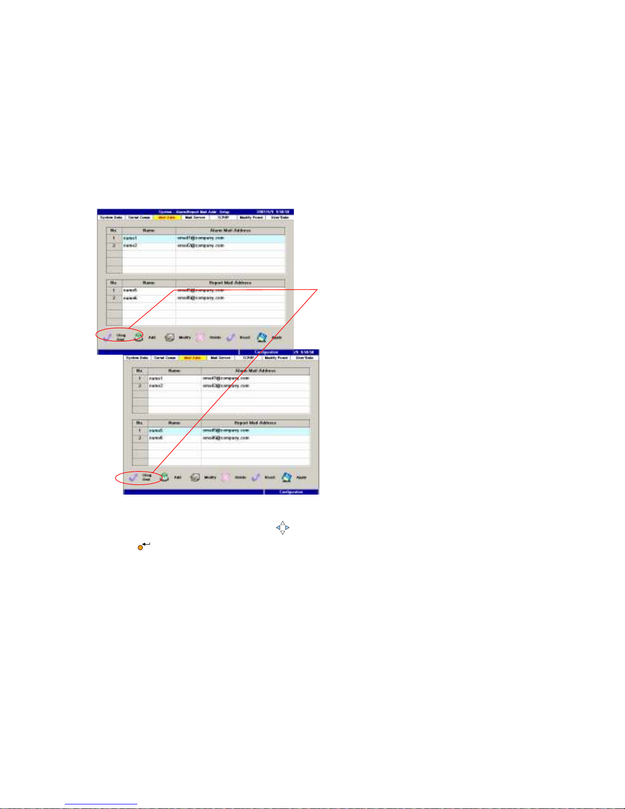
6.1.3 Mailing List Setup
In this section, PM1600 need to know where to send the alarm report and
regular report. Use the set button in the bottom left of the screen to move
around alarm or report mailing list. If edit, add, delete is required, use the
respective button to make the necessary change. Again apply button has to be
click to enter the data.
Change the target mailing list
1. Use the left/right Arrow key to select the Set button and press the Enter
key to toggle between the Alarm mail list and the Report mail list.
1.
Page 55
55
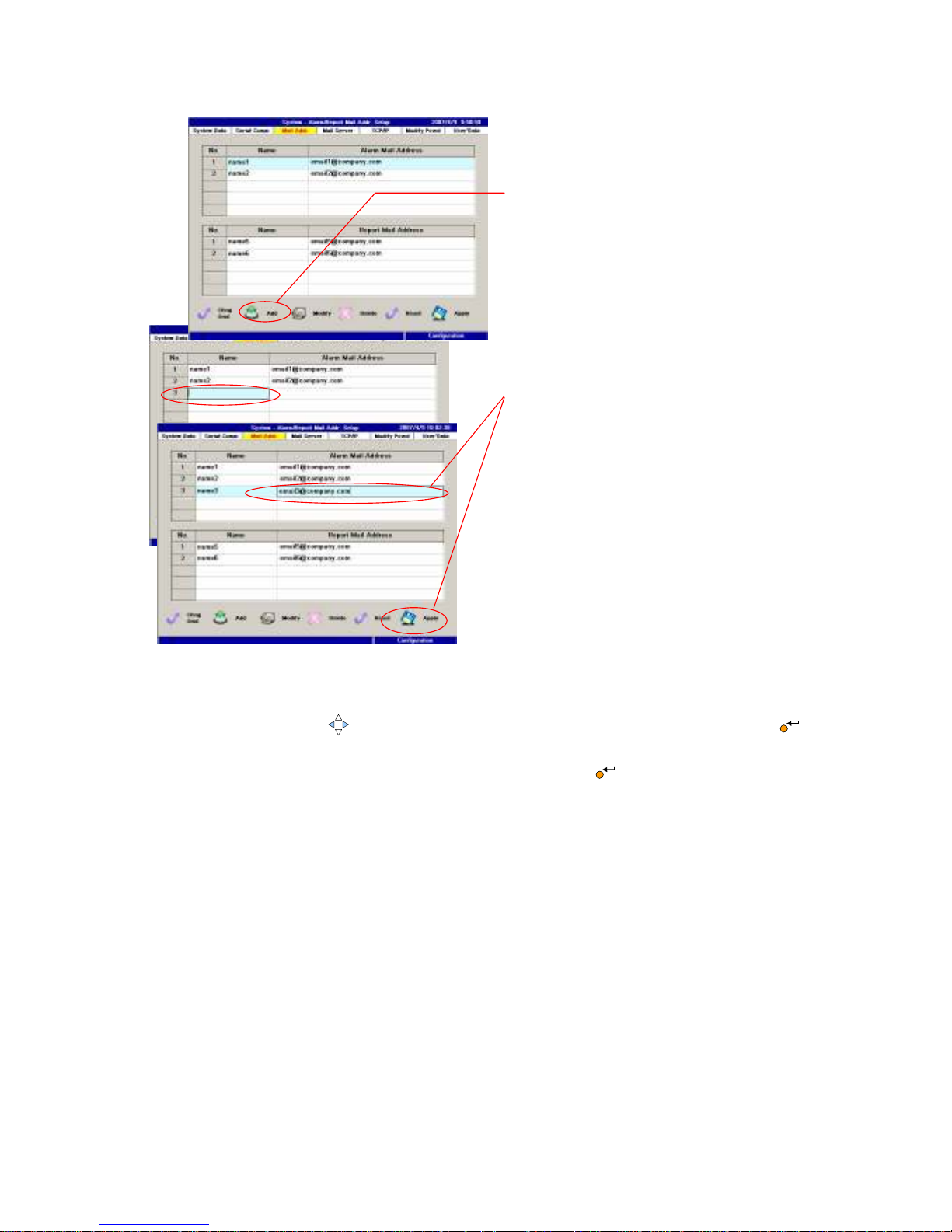
Add a new E-Mail address
1. Use the Arrow key to select the Add button and press the Enter key to
begin to add.
2. Select the Apply button and press the Enter key to apply the new value.
2.
1
.
Page 56
56
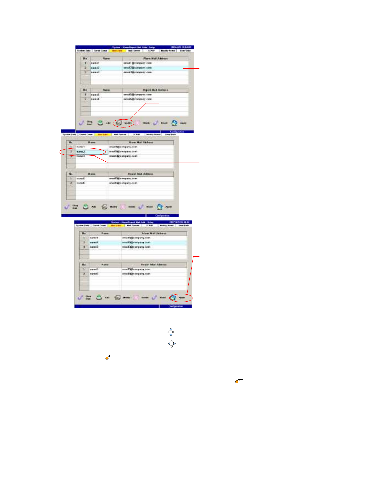
Modify an E-Mail address
1. Use the up/down Arrow key to highlight the desired E-Mail address.
2. Use the left/right Arrow key to select the Edit button and press the
Enter key to begin to modify.
3. Use the screen keyboard to edit both the name field and the address field.
4. Select the Apply button and press the Enter key to apply the new value.
1.
4.
2.
3.
Page 57
57
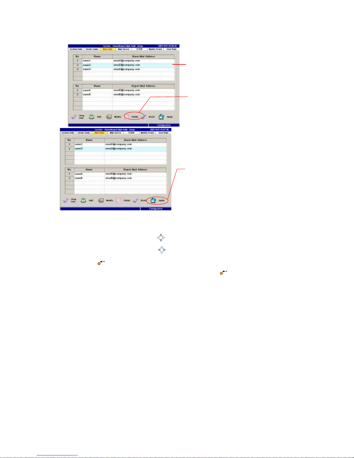
Delete an E-Mail address
1. Use the up/down Arrow key to highlight the desired E-Mail address.
2. Use the left/right Arrow key to select the Delete button and press the
Enter key to begin to modify.
3. Select the Apply button and press the Enter key to apply the deletion.
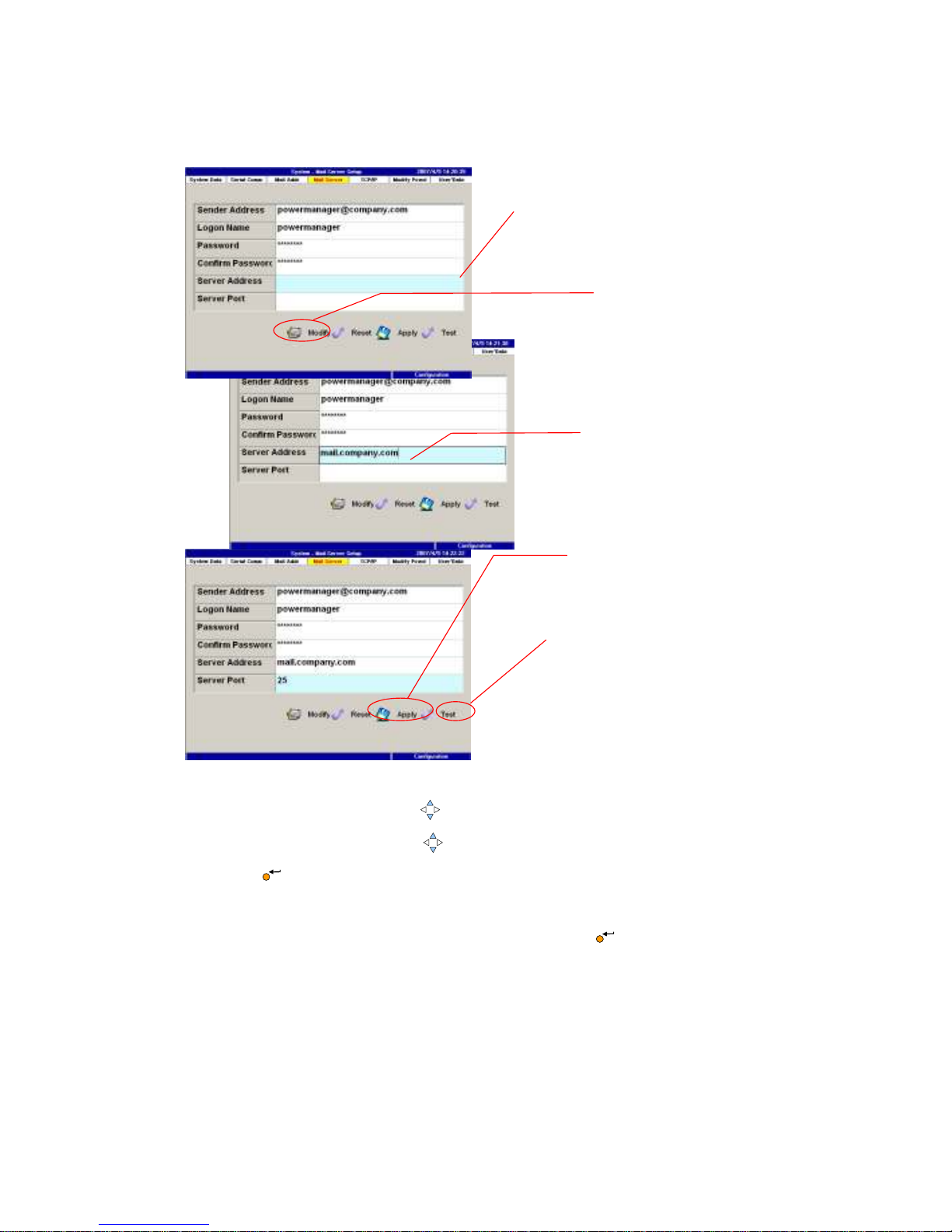
6.1.4 Mail Server Setup
Each PM1600 connected to Ethernet has its own identity as sender address and
login name. Therefore, the receivers will knows where these reports are from.
Obtain the server address and server port from your internet system provider
(ISP) or MIS manager. Assign this PM1600 with unique sender address, login
name, and password to precede the mailing.
1.
3
.
2.
Page 58
58
1. Use the up/down Arrow key to navigate among the fields.
2. Use the left/right Arrow key to select the Edit button and press the
Enter key to begin to edit.
3. Type the screen keyboard to fill out the field.
4. Select the Apply button and press the Enter key to apply the change.
5. Select the Test button to test the SMTP mail server. If succeed, you will get
a successful message, otherwise a failed message will be shown.
6. If succeed, you will get a successful message, or a failed message will be
shown.
1.
4.
2.
3.
5.
Page 59

59
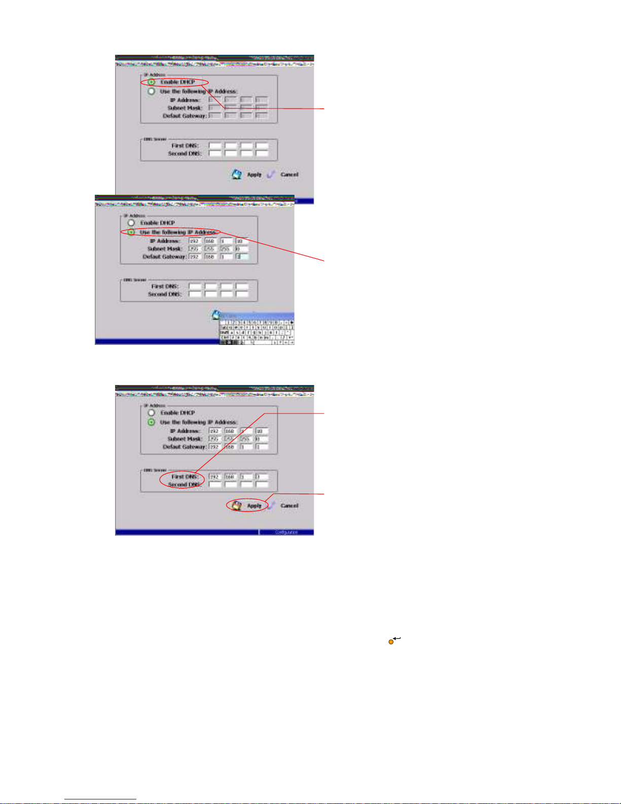
6.1.5 TCP/IP Setup
IF PM1600 is connected with PC directly using Ethernet cable, private IP is used
for both PM1600 and client PC. In this case, PM1600 dose not have email
function since it is not network connected. For example: IP can be assigned as
192.168.n.h., where n is network ID, PM1600 and client’s PC use same number,
and h is host ID which PM1600 and client PC use different number.
If wide area network was employed to connect PM1600 and PC client, two option
of IP address is shown in this page. Always consult with your IT department to
select the option and the needed information such as IP address, subnet mask
and default gateway. Please note-that if DHCP is enable as the selected option, it
is possible that the client PC from remote area may not read PM1600 data since
it uses floating IP address. However, the email function still can send the report.
DNS server section is reserved for future application. Please leave them blank.
Page 60
60
1. Select this option to obtain an IP address from the DHCP server
automatically.
2. Select this option to set the IP address manually using the screen keyboard.
3. The DNS server must be specified if you set the IP address manually, or it
becomes optional.
4. Select the Apply button and press the Enter key to apply the change.
1.
4.
3.
2.
Page 61
61
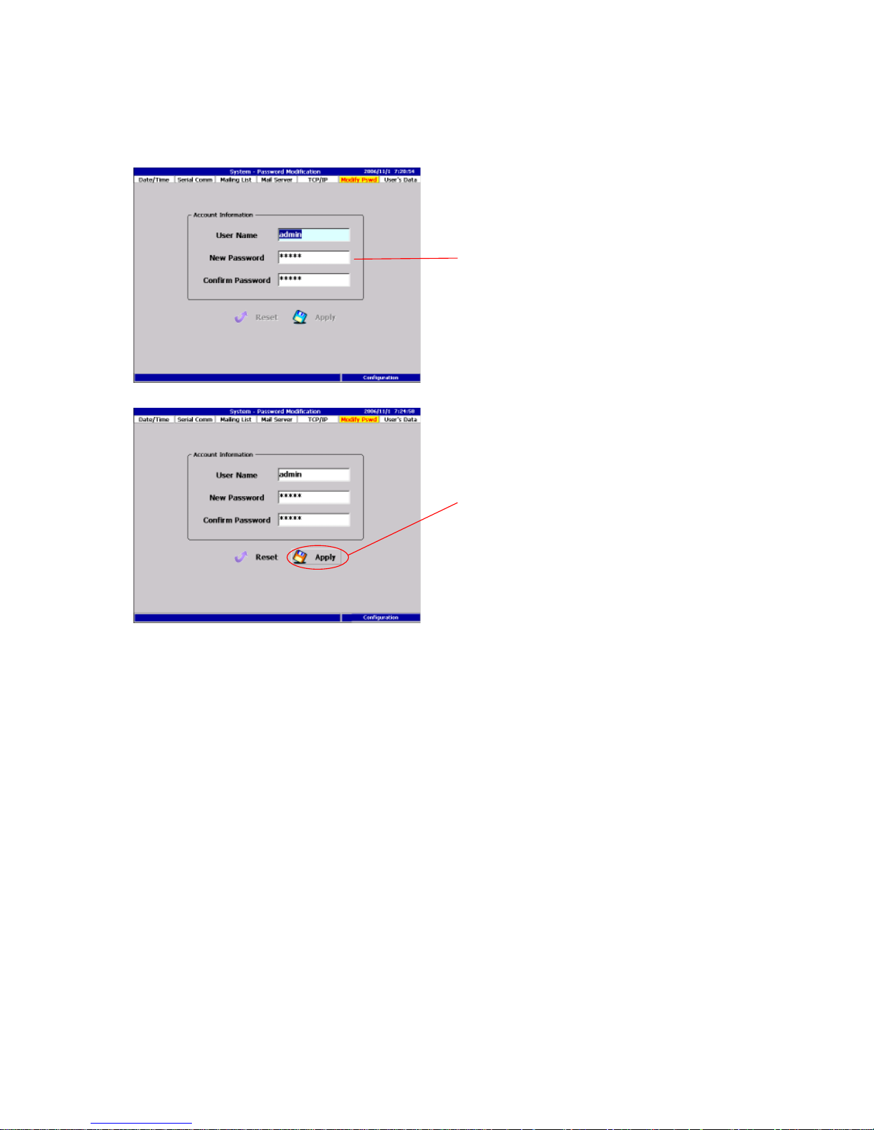
6.1.6 Password Modification
This section allow current user to change his password by entering the
password.
1. Input the new user name and the password.
2. Press the Apply button to apply all changes.
6.1.7 User’s Data Setup
This section is used to manage the privilege to access the PM1600. Fore group
levels of user are designed here as admin, eng. operator and guest. First of all,
this current page can only be seen by admin group which is given the right to
add or delete new users and assign their group levels. In engineer group level,
he can use both runtime and configuration mode, so as to change the PM1600
setting in both mode. Operator level and can only do the change or modification
within runtime mode. In guest level, all he can do is “look”.
For user’s convenient and security, PM1600 in this page is allow users to set if
the system will check operator or engineer ID or not. If check engineer box is
clicked, then password will be asked every time the system switches to
configuration mode. If check operator is triggered, them password will be asked
when change any status in runtime mode.
1.
2.
Page 62
62
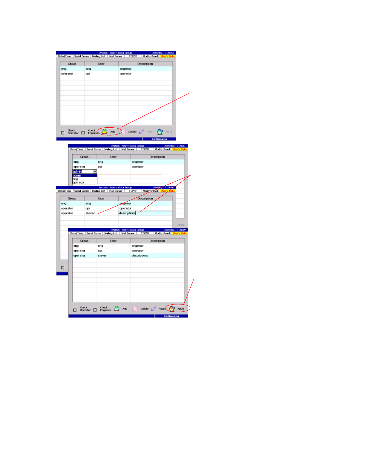
Add a new account
1. Press the Add button to start adding an account.
2. Select the authority level and in put the user data.
3. Press the Apply button to apply all changes.
2.
1.
3.
Page 63
63
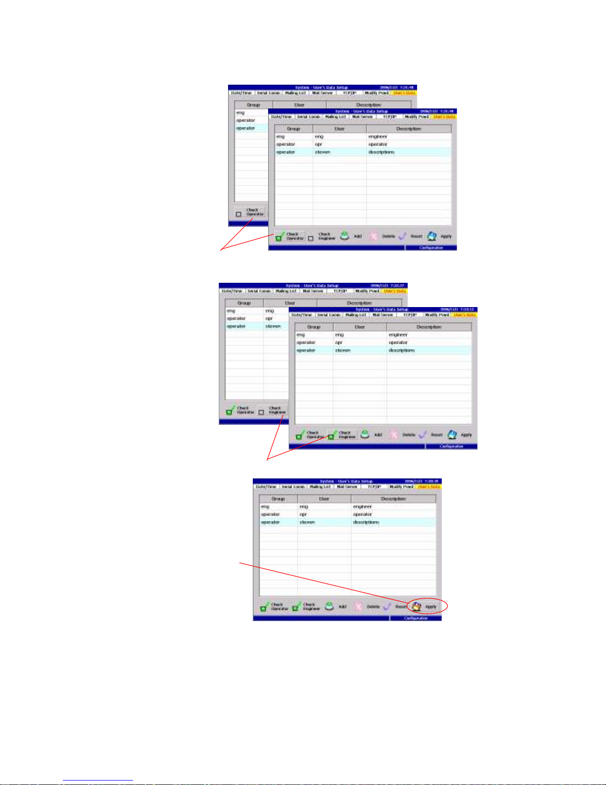
Set up the security check
1. Check the “Check Operator” to enable security check in the runtime mode.
2. Check the “Check Engineer” to enable security check while switching into the
configuration mode.
3. Press the Apply button to apply all changes.
1.
3.
2.
Page 64
64
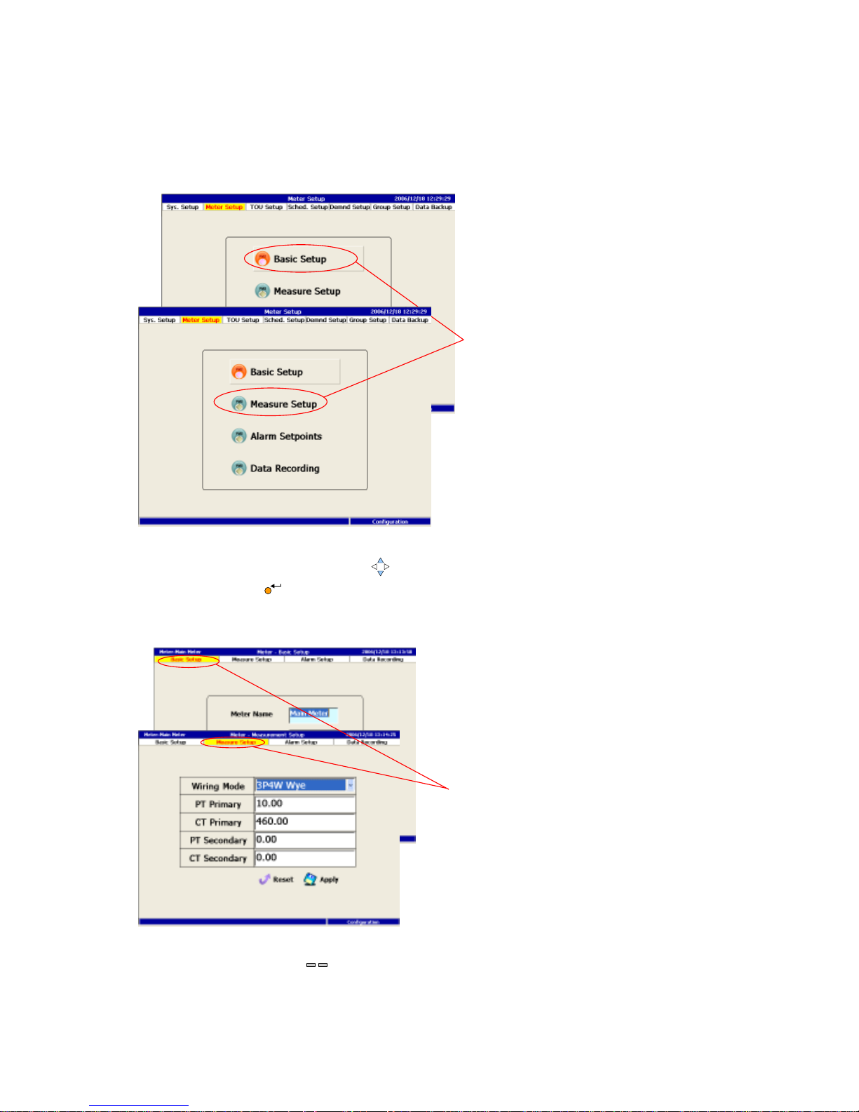
6.2 Meter Setup
In this section, users can setup every individual meter for their own properties.
There are four setup have to completed.
1. Use the up/down Arrow key to navigate among the functions, then press
the Enter key to perform.
1. Press the Page key to switch from the neighbor function.
1.
1.
<
PAGE >
Page 65
65
6.2.1 Basic Setup
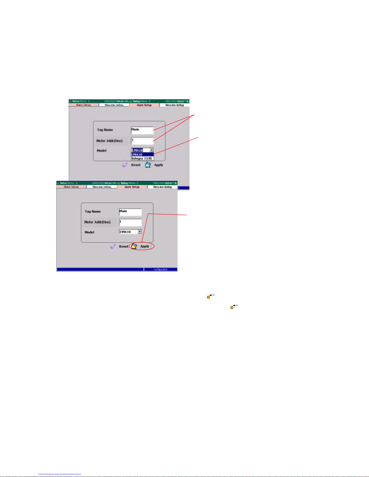
In this section, PM1600 like to know every meter’s ID like the Tag name, the
location and the Model of the meter. To enter the right meter address, users
have to set the address code in meter side or obtain the address code from
meter’s manufacturer and enter this number in this page.
1. Use the screen keyboard to fill out the two fields.
2. Select the model and press the Enter key to choose.
3. Select the Apply button and press the Enter key
to apply the change.
4. For adding next meter, click Mt/Gkpt button.
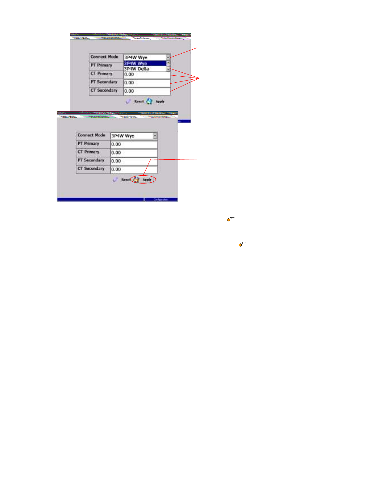
6.2.2 Measure Setup
For correctly reading the right data, users have to specify the wiring method and
values of primary PT&CT ratio and second PT&CT ratio. These information can
be obtained from field engineers on system integrator.
3. 4.
2
.
Page 66
66
1. Select the wiring mode and press the Enter key to choose.
2. Use the screen keyboard to fill out these fields.
3. 2. Select the Apply button and press the Enter key to apply the change.
6.2.3 Alarm Setup
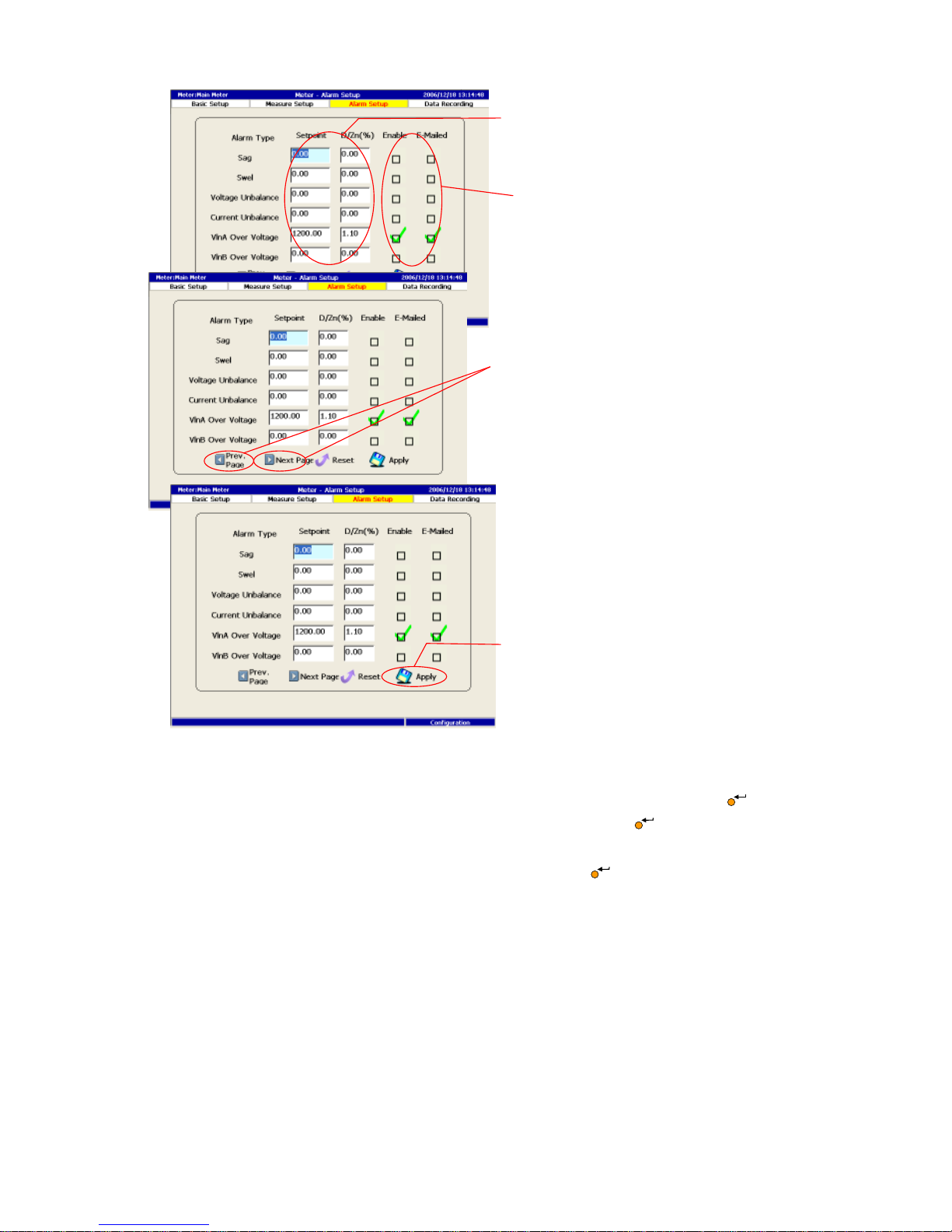
PM1600 designs Sag, Swell, Voltage imbalance, current imbalance, lines over
voltage…etc. for alarm, as shown in the window. These data for alarm from each
meter are data provided by meter or defined by users, and PM1600 will perform
the alarm function with comparison of set point setting. On the other hand if
meter dose not provide data, then PM1600can not perform the alarm function.
Users are asked to enter the set point and dead zoon, and checked the En/Dis
(Enable and Disable) check box . Users can also decide to E-mailed the alarm
data by clicking the check box of e-mailed.
3
.
1.
2.
Page 67
67
1. Use the screen keyboard to fill out these fields.
2. Toggle the status of these check boxes by pressing the Enter key
3. Select the Prev/Next button and press the Enter key to navigate
among the alarm pages.
4. Select the Apply button and press the Enter key to apply the change.
4.
1.
2.
3
.
Page 68
68
6.2.4 Trend Setup/ DATA Recording
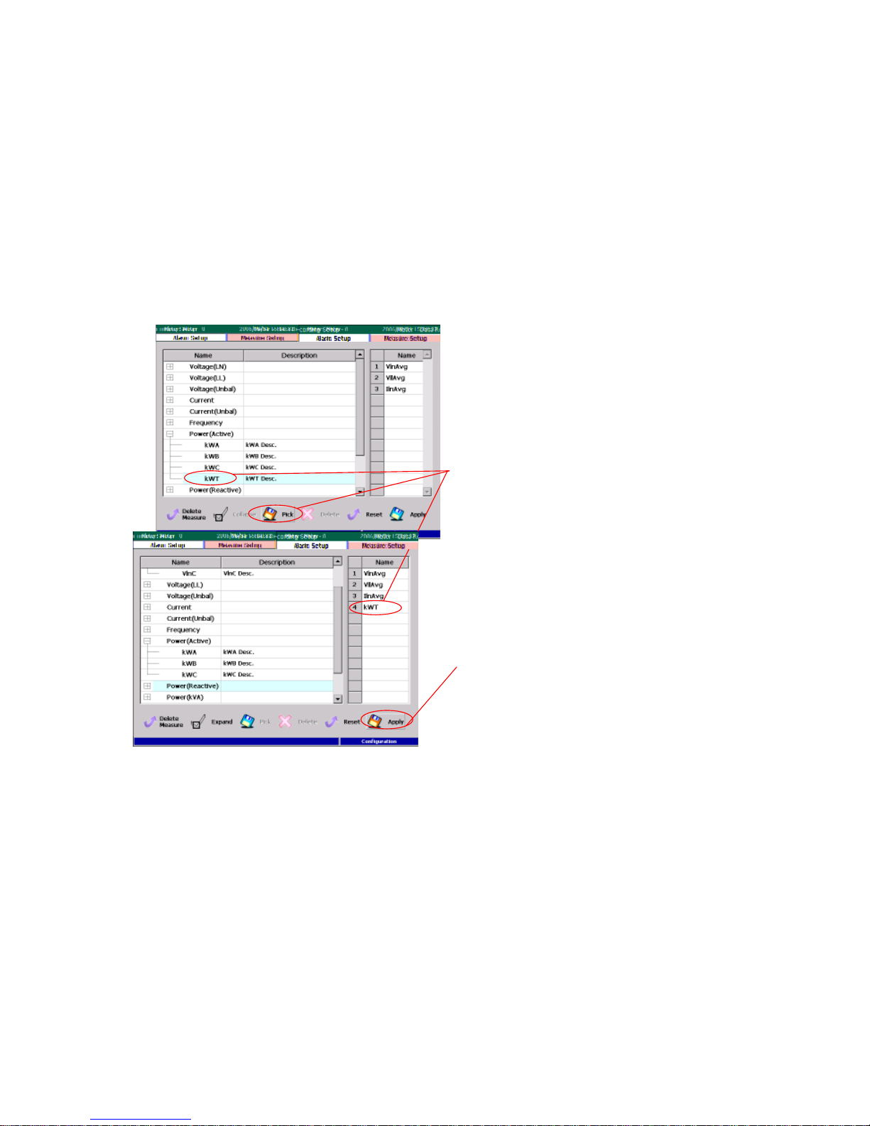
PM1600 allow users to select the measuring data to save for further display and
analysis. User select the item listed in the left grid and click the add button to
the right grid which display the item of data will be saved and displayed in the
runtime mode.
Users can use the change grid button and move the highlight to the right grid to
delete the item in the right grid. Up to 12 measurement can be saved and
displayed.
1. Select the desired measure, then press the Pick button to choose.
2. Press the Apply button to start applying the changes.
2.
1.
Page 69
69
6.3 TOU Setup
Tariff change as season, weak, day etc. In order to understand the expense of
electricity at different time interval, TOU is designed to let the user to specify the
various time type according to the local utility tariff policy.
1. Use the up/down Arrow key to navigate among the functions, then press
the Enter key to perform.
Perform a function from the detailed dialog:
2. Press the Page key to switch from the neighbor function.
1.
2.
< PAGE >
Page 70
70
6.3.1 Season Setup
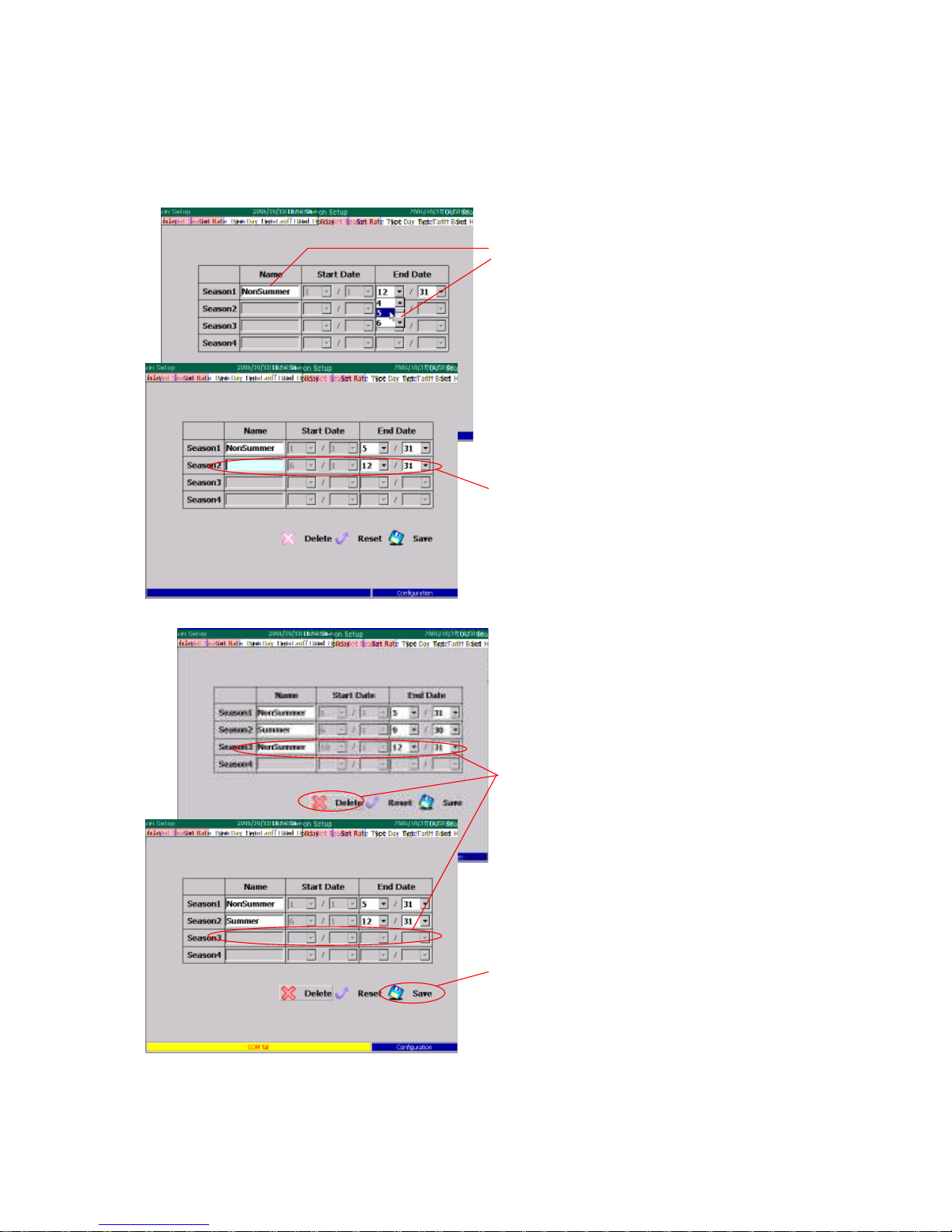
PM1600 allow you to setup up to four seasons in one year. Users have to specify
the start date for every season. Operations are described below.
2.
4.
.
3.
1.
Page 71

71
1. Use the screen keyboard to type the season names, and state date, then
press the Enter key to choose. PM1600 will assign the day before state
date of next season as the end date automatically.
2. The Delete function deletes the last season.
3. Select the Save button and press the Enter key to apply the change.
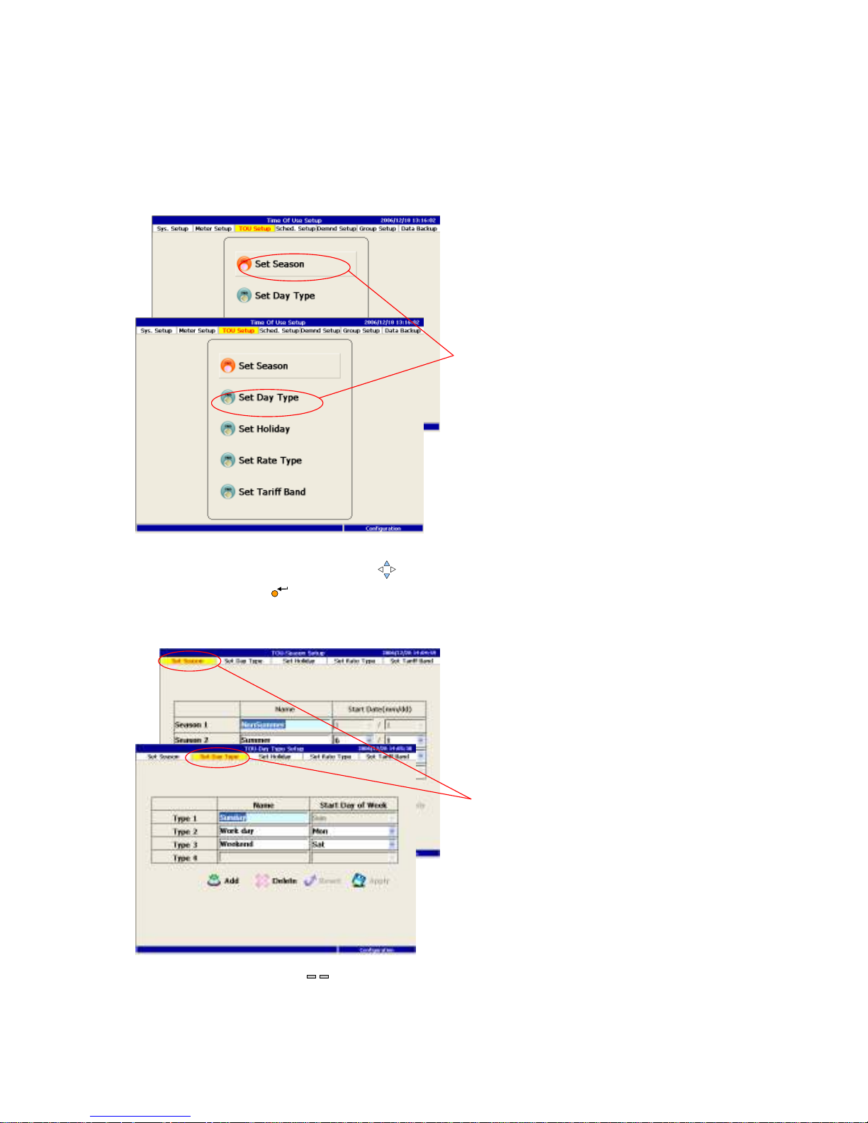
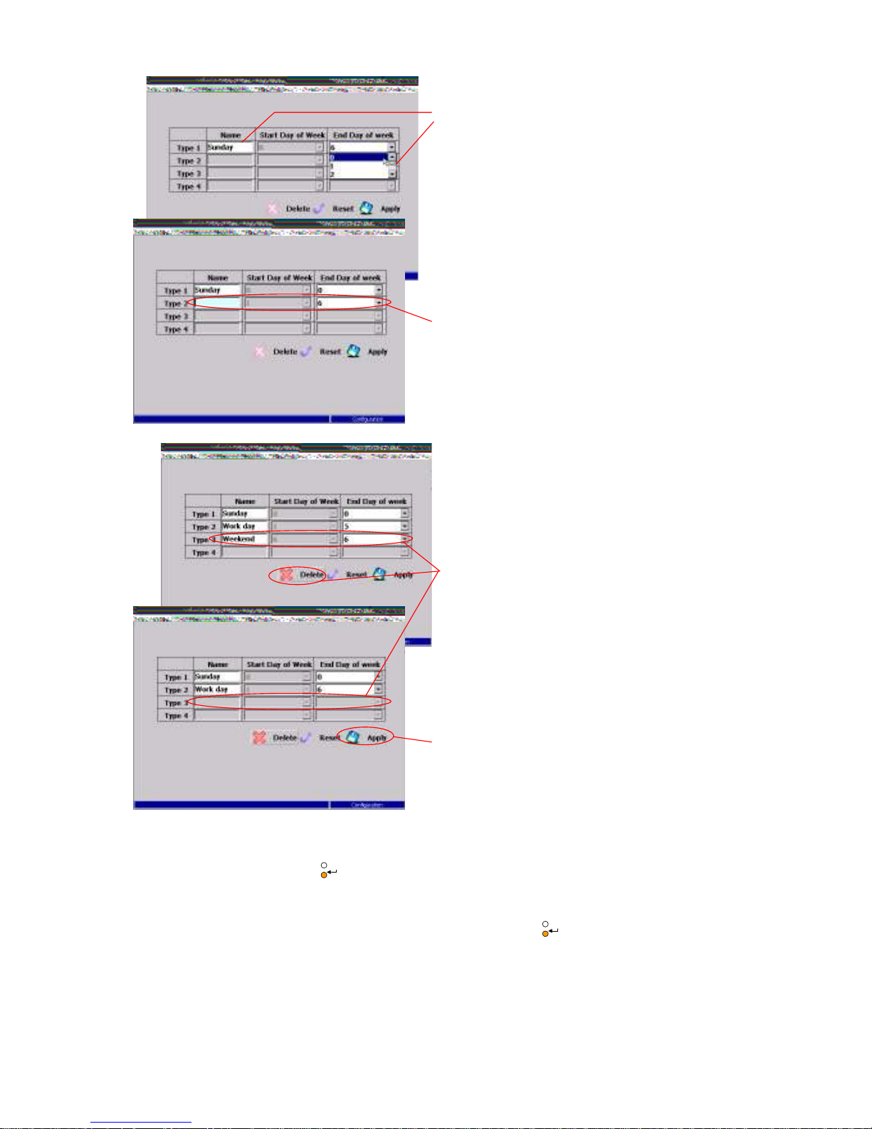
6.3.2 Day Type Setup
This section mainly to define the day type in one week, for examples: weekday
and weekend. Users only need to specify the state date and PM1600 will provide
end date as one day before next start date.
ESC
ESC
Page 72
72
1. Use the screen keyboard to type the day type. Select the end weekend and
press the Enter key to choose.
2. The Delete function deletes the last day type.
3. Select the Apply button and press the Enter key to apply the change.
2.
4
.
3.
1.
ESC
ESC
Page 73
73
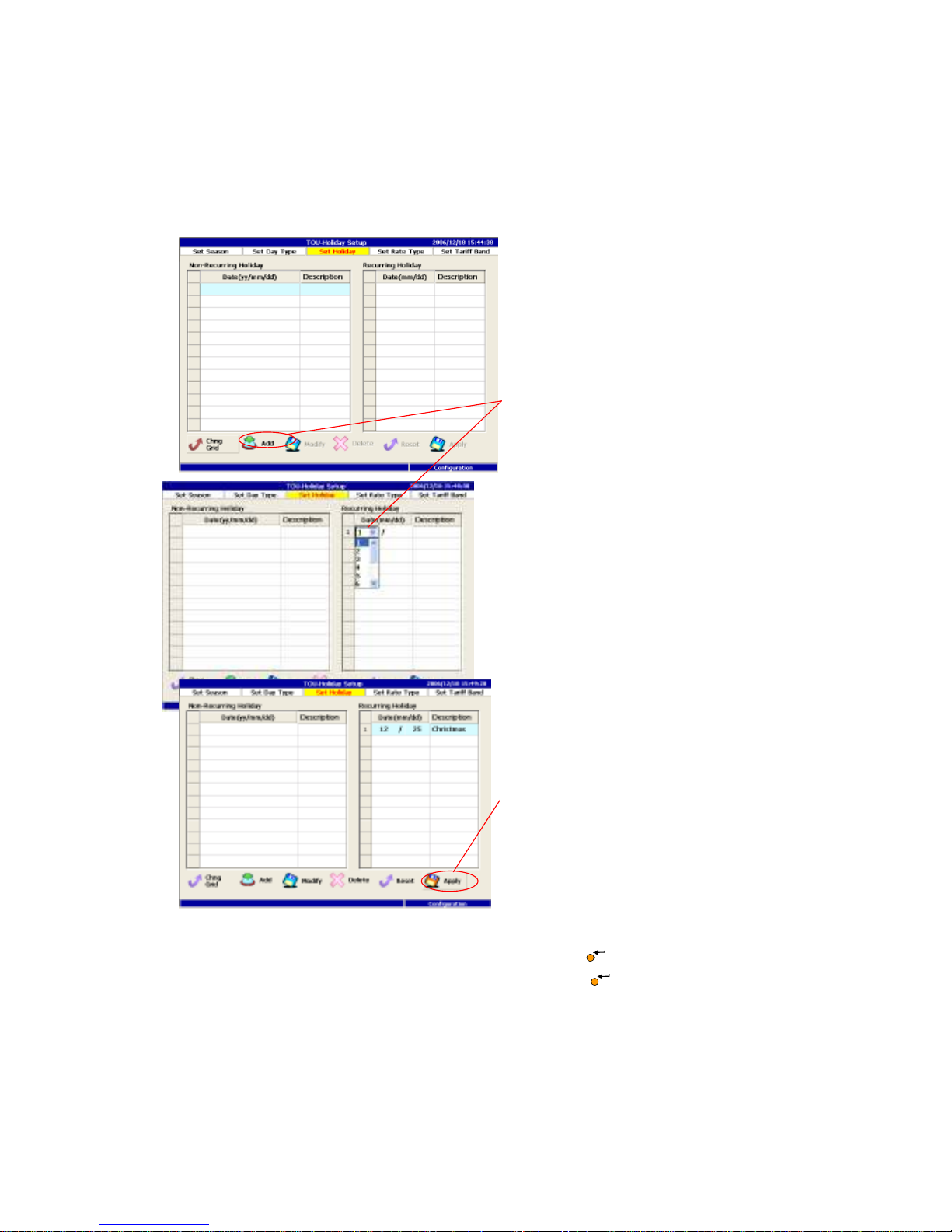
6.3.3 Holidays Setup
In the section, holiday will be entered whether they are recurring every year like
New Year Day or non-recurring day like Labor Day or Memorial Day. Users
select recurring or non-recurring grid to enter the data first.
1. Select the Add button, then press the Enter key to add a holiday.
2. Select the Apply button and press the Enter key to apply the change.
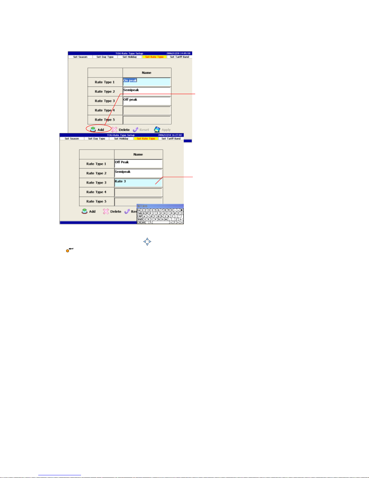
6.3.4 Rate Type Setup
To calculate the expense of electricity, PM1600 allow users to enter different
rate type, for instance: peak rate, non-peak rate, semi peak rate…, or rate1,
rate2, etc. Detail operation is described below.
2.
1.
Page 74
74
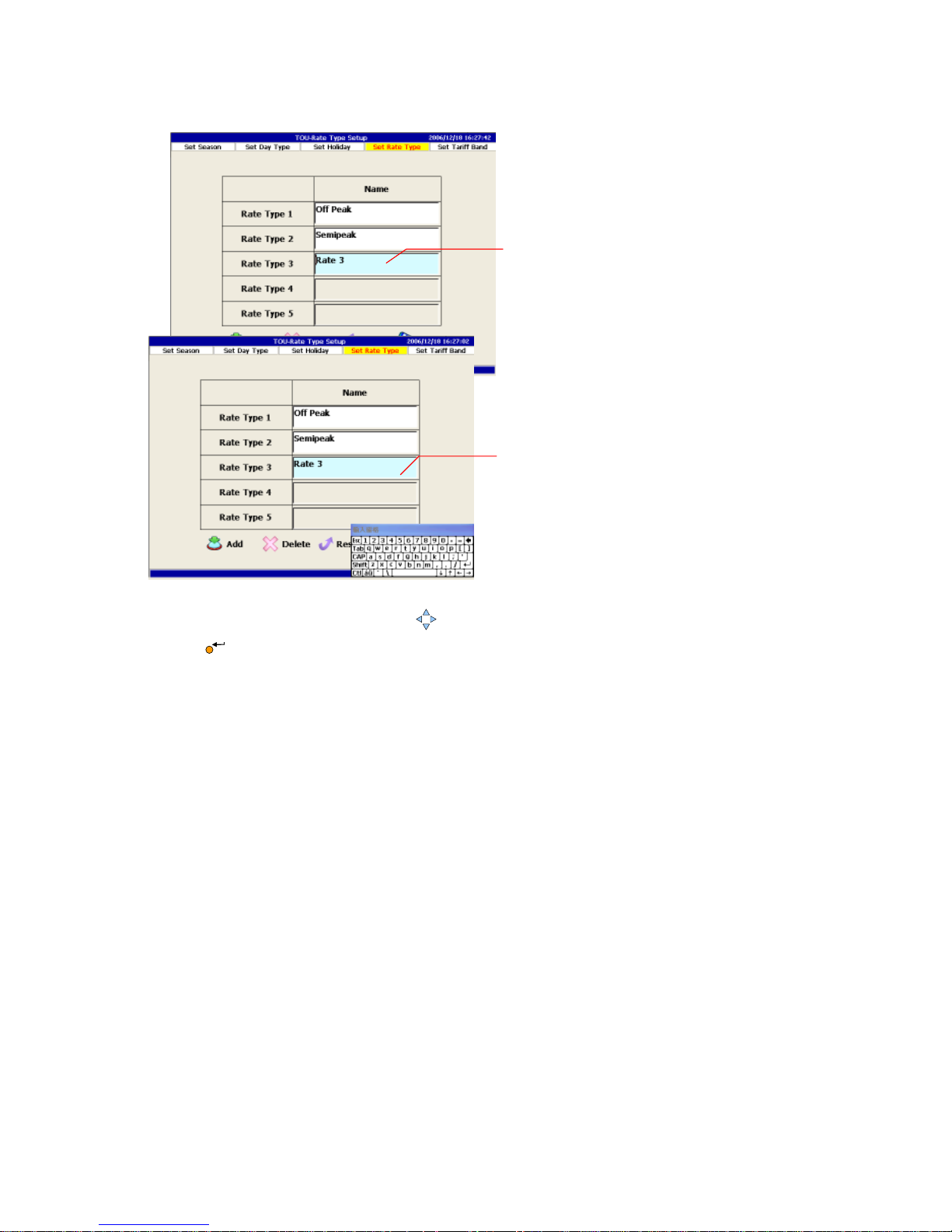
Add a new Rate Type
1. Use the four Arrow key to select the Add button and press the Enter key
to begin to add.
2. Use the screen keyboard to type the rate type name.
1.
2
.
Page 75
75
Modify a Rate Type
1. Use the up/down Arrow key to locate the rate type, then press the Enter
key to begin editing.
2. Use the screen keyboard to type the rate type name.
1.
2.
Page 76
76
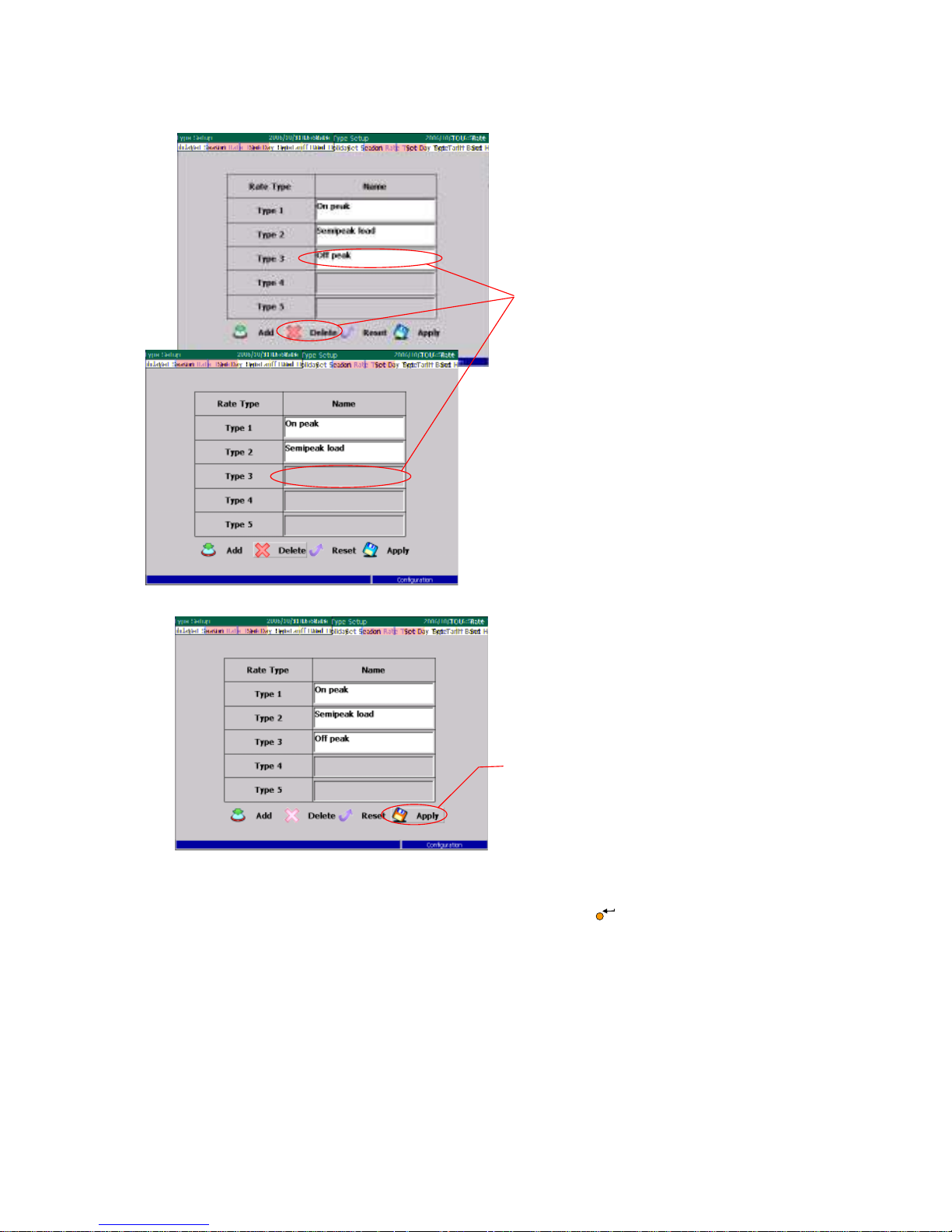
Delete a Rate Type
1. The Delete function deletes the last Rate Type.
2. Select the Apply button and press the Enter key to apply all the
changes.
1.
2.
Page 77
77
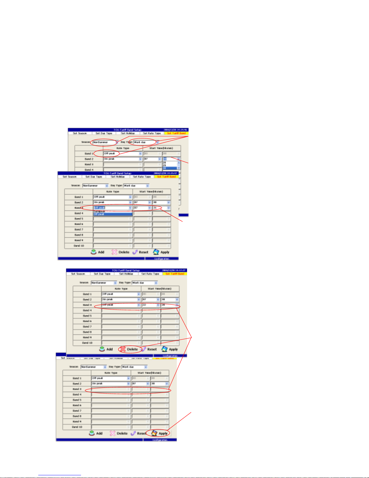
6.3.5 Tariff Band Setup
After setting season, day type, rate type, Tariff band can then be determined in
this section. At each band, users have to specify season, day type, rate type, and
start time complete the each band setting. For instance, summer, weekday,
rate1 is from00:00 to 07:00 as band1, rate3 is from 07:01 to 21:00 as band2
and rate1 is from 21:01 to 23:59 as band3.
To set weekend, just change weekday to weekend and set the band for that day
again.
3.
5
.
4
.
2.
1.
Page 78

78
1. Define a tariff band by selecting the related season, day type, rate type.
2. Then select the end time for the tariff band.
3. If the setting is not finished, the default end time of the next tariff band will
be provided automatically.
4. The Delete function deletes the last tariff band.
5. Select the Save button and press the Enter key to apply the change.
If seasons, day type or rate type has been modified, PM1600 will ask users to
redefine all the tariff band before leaving the configuration mode. Since these
change will also affect the setting of demand control, users will also have to redo
the setting in demand control section before leaving the configuration mode
also.
ESC
Page 79
79
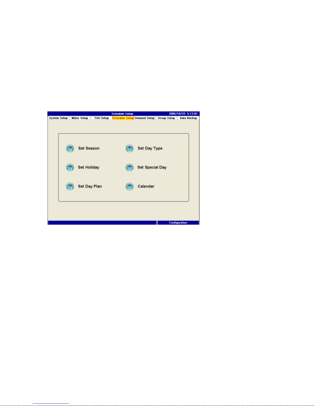
6.4 Schedule Setup
In chapter 6.3 is mainly to setup the detail tariff bands for each day in every
week and season for the whole year. It is used to calculate the electricity
expanse. In this section, all the time zone are redefine to setup a day plan to
control the relays. Therefore, PM1600 require you to enter the season setup, day
type setup…etc. again for day plan to control relays which should differ from
tariff bands in chapter 6.3. Again schedule setup is designed for turn on/off for
the devices like a timer.
Page 80
80
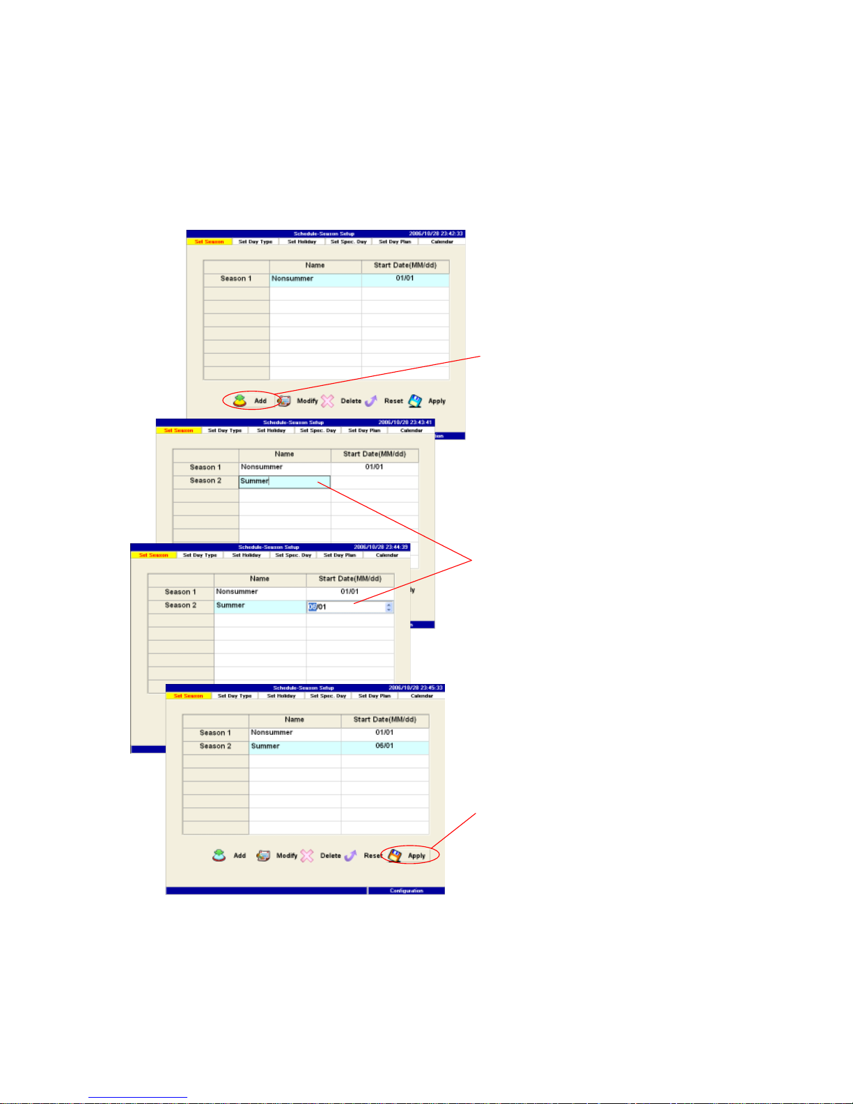
6.4.1 Season Setup
Users can define seasons according to its own application, such as: winter
break, spring semester or summer energy saving season, etc. Users key in only
the start date (mm/dd). One day before next season start day will be the end
date of the previous season automatically.
1. Press the Add button to start adding a season type.
2. Input the season type name and select the start date.
3. Press the Apply button to apply all changes.
2.
1.
3.
Page 81
81
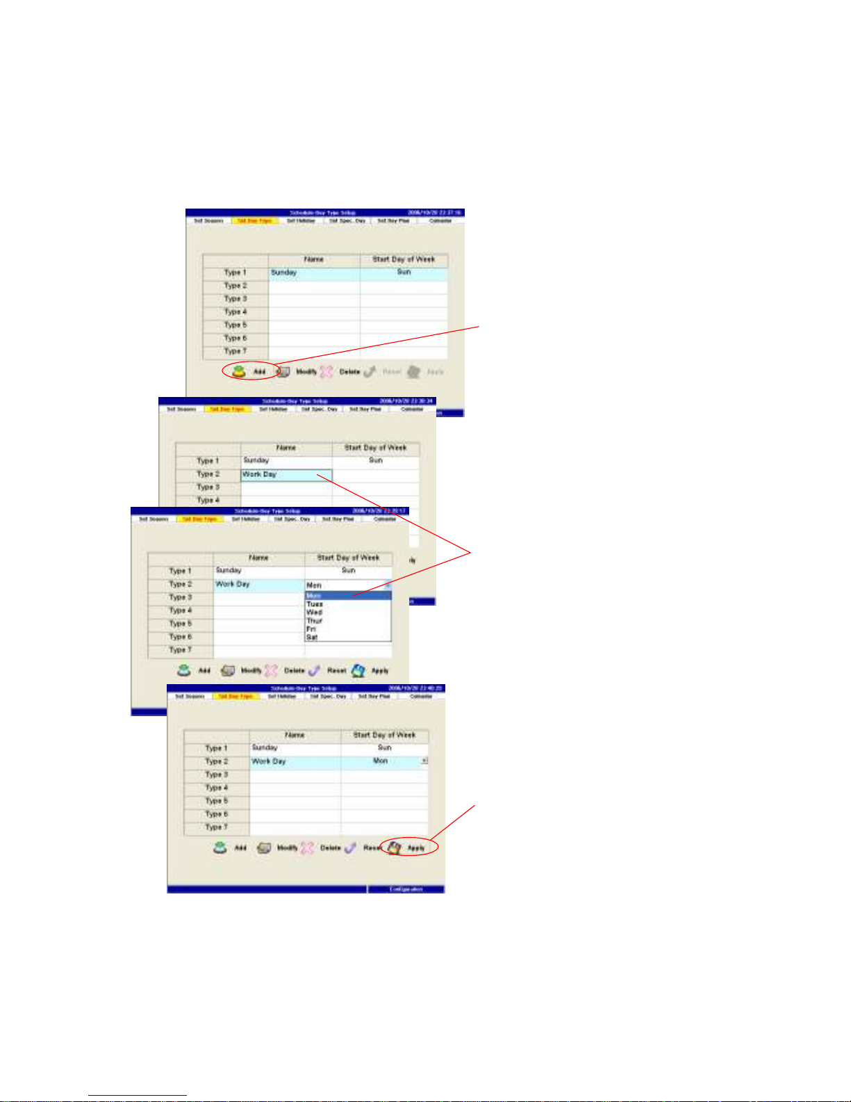
6.4.2 Day Type Setup
Like day type setup in TOU section, PM1600 provide up to 7day types in a week
for users to define. Like previous section, one day before the next day type will
be assigned to be the end date of previous day type.
1. Press the Add button to start adding a day type.
2. Input the day type name and select the start date.
3. Press the Apply button to apply all changes.
2.
1.
3.
Page 82
82
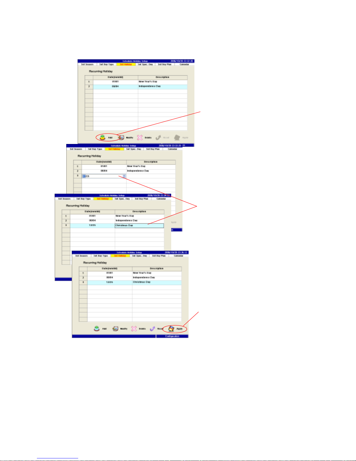
6.4.3 Recurring Holidays Setup
All the recurring holiday is entered in this page.
1. Press the Add button to start adding a recurring holiday.
2. Select the month and day, then input the description.
3. Press the Apply button to apply all changes.
2.
1.
3.
Page 83
83
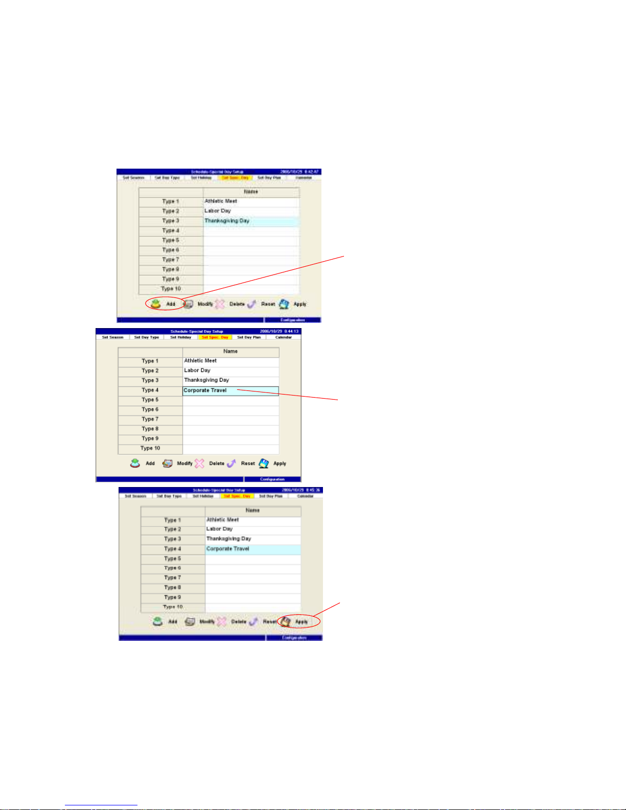
6.4.4 Special Day Type Setup
Besides recurring holiday, PM1600 is allowed to set special day type other than
weekday, weekend according to user’s application, for instance, the New Year
eve day, long week end etc. The setting in this section is similar to previous
section.
2. Input the name of the
special day type.
1. Press the Add
button to start
adding a special day type.
3. Press the Apply button to
apply all changes.
1. Press the Add button to start adding a special day type.
2. Input the name of the special day type.
3. Press the Apply button to apply all changes.
Page 84
84
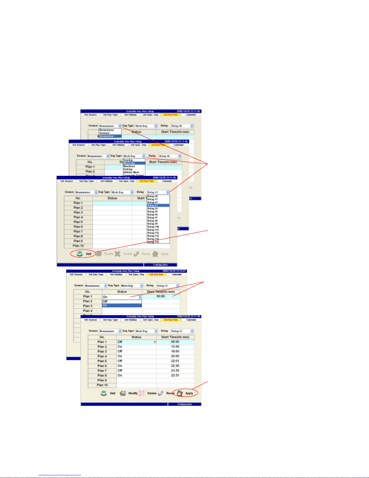
6.4.5 Day Plan Setup
After season, day types are determined, for every relay users should plan this
particular on/off schedule. For example, chill relay will be off from 00:00 and on
at 7:30, off 12:00, then turn on again at 2230. The user can set this relay
accordingly. Those relays will be set for every season and every day type if
schedule control is necessary.
1. Select the target Season/Day Type/Relay to edit.
2. Press the Add button to start adding a schedule.
3.
1.
2.
4.
Page 85
85
3. Choose the trigger signal and the start time for each schedule.
4. Press the Apply button to apply all changes.
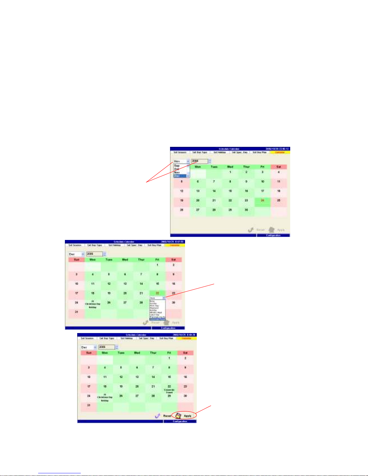
6.4.6 Day type Setup using Calendar
PM1600 provide the user a convenient way to setup day type directly through
calendar. We suggest that users should use this function to setup those
non-recurring special day types. The user can also use this function to change
the original setting for one-time event. For example, change new year day from
holiday to workday, when none is chosen, it means the scheduling is directed by
previous day type setting.
2. Choose the desired event
for the schedule date.
1. Select the month and the year
to change the monthly calendar,
then locate the target date to
schedule.
3. Press the Apply button to
apply all changes.
Page 86

86
1. Select the month and the year to change the monthly calendar, then locate
the target date to schedule.
2. Choose the desired event for the schedule date.
3. Press the Apply button to apply all changes.
Page 87
87
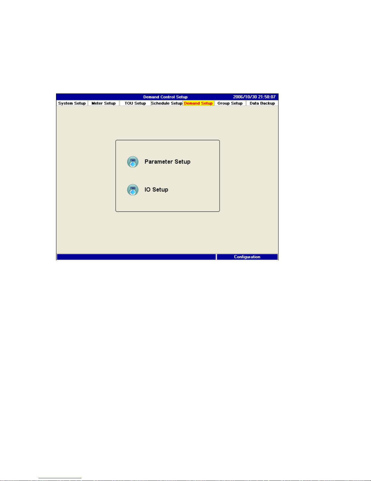
6.5 Demand Control Setup
This section is one of the most important function of PM1600. Users are
required to setup all the parameters for PM1600 to carry out the demand
control accordingly.
Page 88

88
6.5.1 Parameter Setup
PM1600 is designed for users to control demand according to various season
and rate type due to different contract capacities. Users have to setup every
season type and rate type to carry out demand control differently. Therefore,
you have seasons and rate types combination to set this page.
To setup demand control, select one season type go through all the different rate
types such as peak, off peak and semi peak.
Under every case, the rest of information in this page has to be entered. The rate
column means electricity rate per kwh for that season and rate type. “Contract”
column means contract capacity. Target column is the capacity that demand
control will follow as the set point.
For alarm value, a percentage above the target value is required to enter here.
For example 5%, then 5 is entered. Shutdown limit is the percentage off the
target value that the PM1600 will start load shedding when the predicted
demand value is above the upper bound of shutdown limit, or start load
reinstall when the predicted demand value is lower then the lower bound of
shutdown limit. In another word, away from the shutdown limit zone the
PM1600 will execute load shedding or reinstall. If within the zone, the system
will not automatically turn the relay on or off. Therefore the percentage of
shutdown limit is critical in doing demand control, 10% is a good point to start
with.
Target meter is the meter in which the reading of KW will be used to carry on the
demand control as the target, which usually is the main meter of the system.
PM1600 has two options to perform the demand control:blocking mode and
rolling mode. The different of these two modes please refer to the reference(or
appendix). The demand time interval is depend on the local power company
policy, usually is 15 minutes.
If blocking mode is selected, PM1600 will ask the time then it will start doing
control. Here we suggest 3 min. The PM1600 won’t do any control action until
3min. into blocking period.
If rolling mode is selected, subinterval no. will be entered to roll the period
accordingly. If 3 is entered, then every 5 minutes(15/3=5)the data will be
replaced to calculate the demand.
Page 89

89
The last item is shed mode which users will determine the priority of shedding.
If sequence mode first is selected, PM1600 will do load shedding starting from
the sequence first mode list, then followed by the priority first mode list. If
priority first is selected here, PM1600 will do the load shedding starting from
priority first list then sequence first list later. Please also note where sequence
first mode is executed, the relay which on the top will be turned off first when it
is necessary, and followed by the second, third…etc. As the load reinstalled
start, the first relay, which is turned off, will be reinstalled first also. However, in
the priority first mode the relay which is turned off first will be reinstalled lastly
since it is the lowest priority for power usage.
Page 90
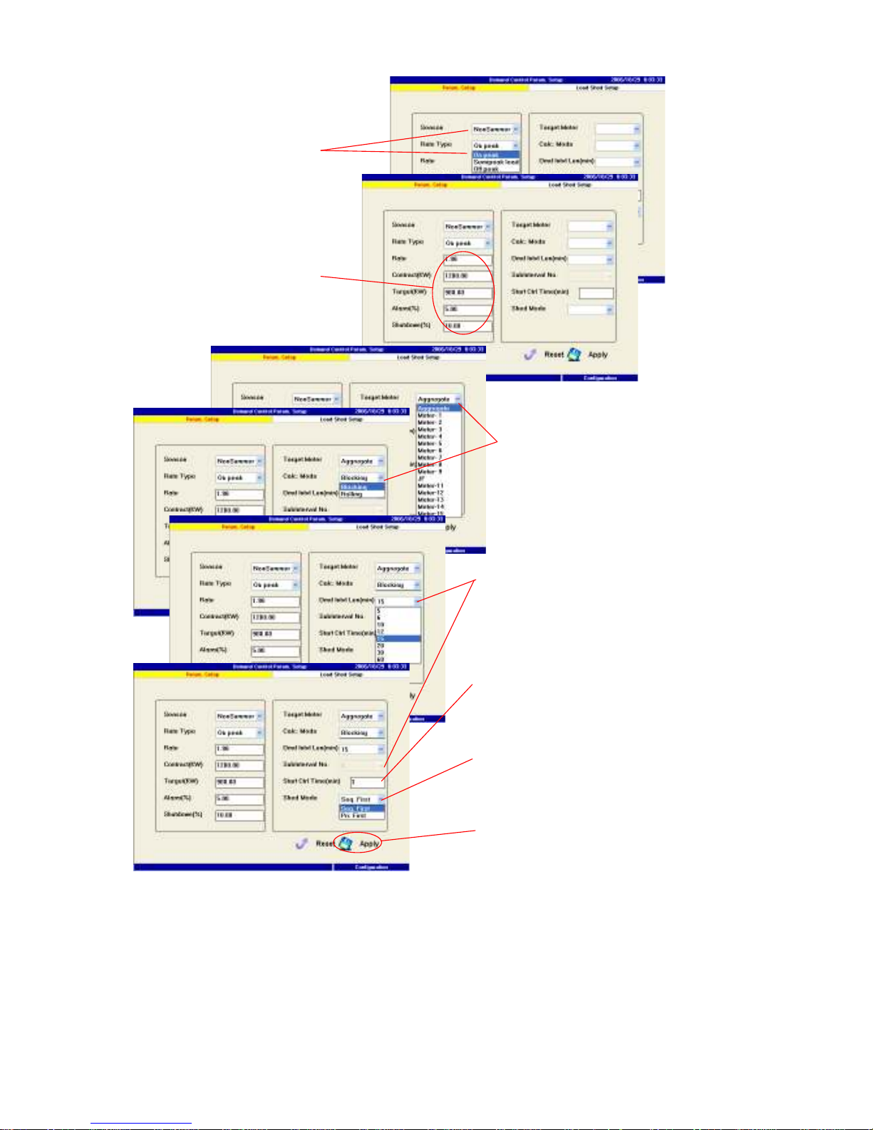
90
1. Select the target seasonal demand rate to edit.
2. Set properties and limits of this target demand rate.
3. Choose a meter as the power usage feeder. Then determine the method to
calculate the demand.
4. Specify the demand interval. If “Rolling” mode is adopted, the subinterval
should also be assigned.
3.
1.
7.
2.
4.
5
.
6.
Page 91

91
5. set restart time of the demand controller in each demand interval.
6. Specify the precedence between the sequential shedding and the priority
shedding.
7. Press the Apply button to apply all changes.
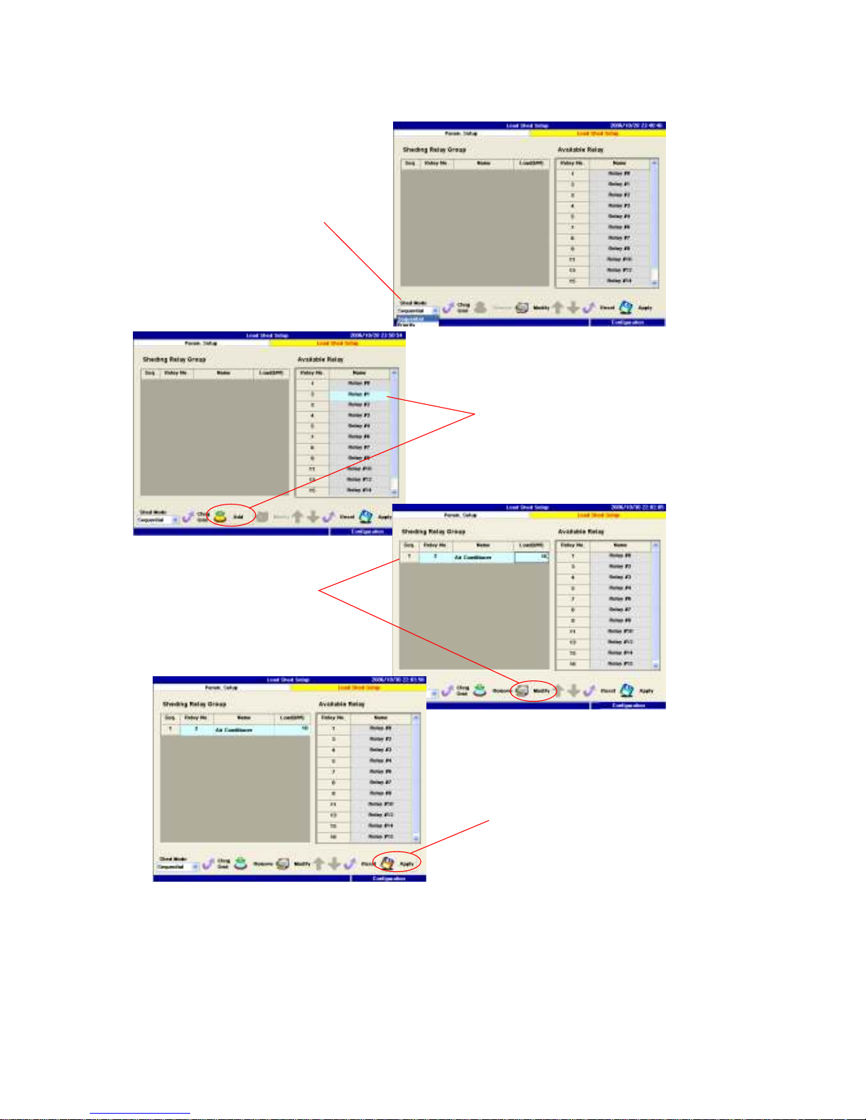
6.5.2 Load Shed Setup
In this section, load control will be carried out through turn the relay off and on.
In this page, PM1600 will list all the available relays on the right hand side grid.
Users will establish the priority of the relay that will be controlled accordingly by
selecting the available relays and add to left side grid as the priority list. Users
have two lists to complete, one for priority first and the other is sequence first.
The different of these two lists are explained in previous section.
Page 92
92
Enable a relay to shed load
1. Select the target relay group to edit.
2. Choose the desired relay and press the Add button to join into the target relay
group.
3. Press the Modify button to change the relay name and the amount of power.
4. Press the Apply button to apply all changes.
2.
1.
4.
3.
Page 93
93
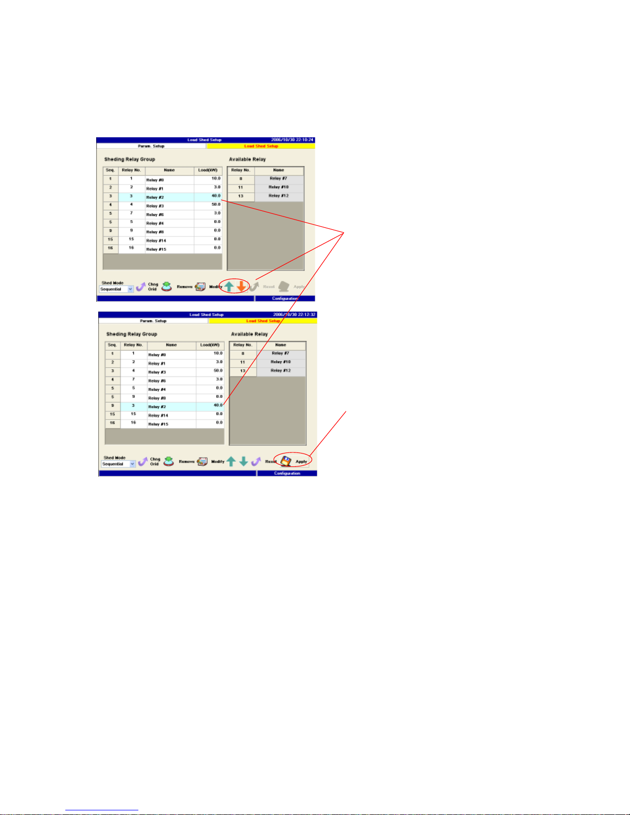
Adjust sequence of load shedding
The priority list can also be adjusted when it is necessary, by the following
steps.
1. Highlight the target relay and press the Up/Down button to change its
sequence.
2. Press the Apply button to apply all changes.
1.
2.
Page 94
94
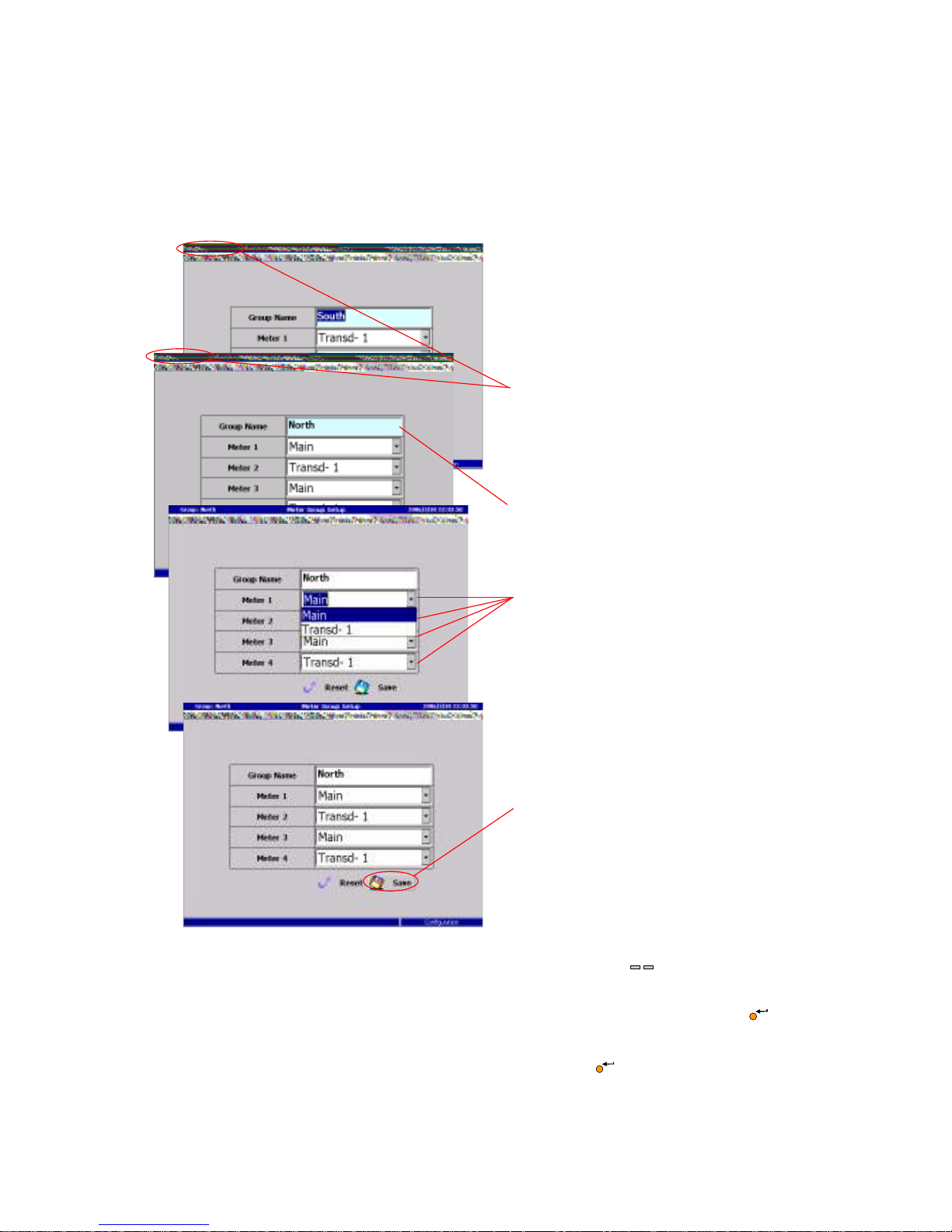
6.6 Group Setup
Since PM1600 can connect up to 16 meters, users can group up to four meters
as one group, and then the data will be shown together in the runtime mode.
This function will allow users to compare data conveniently.
1. Select the desired group by pressing the Device key .
2. Use the screen keyboard to type the group name.
3. Select the desired meters for this group, then press the Enter key to
choose.
4. Select the Apply button and press the Enter key to apply the change.
1.
2.
3.
4.
< TD/GRP >
Page 95
95
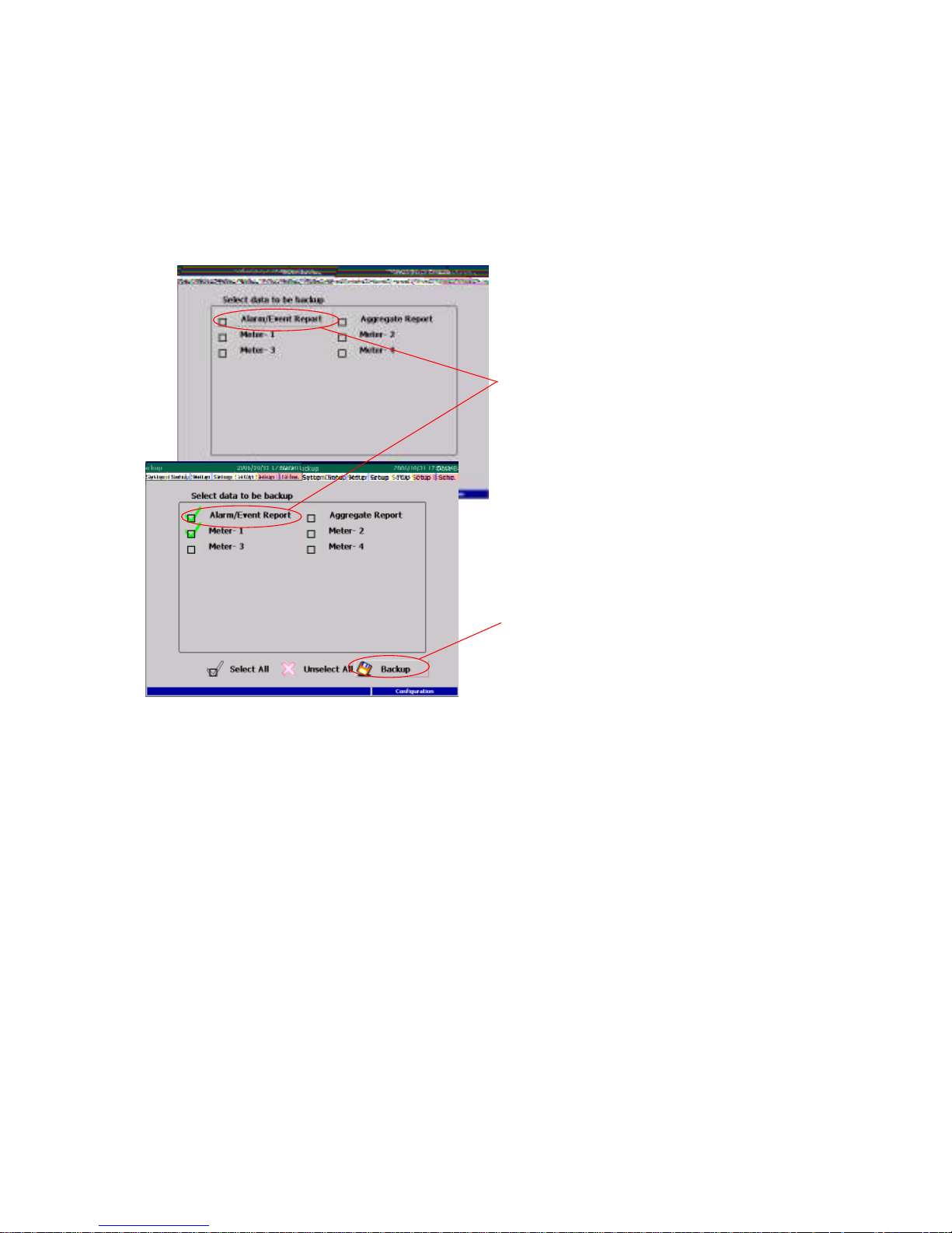
6.7 Data Backup
In this section, PM1600 allow users to backup the data in its memory to either
PC or USB flash driver. If back up is carried out by web client, the data will be
stored in PC. If back up is performed by host machine through USB, the data
will be stored in USB flash driver.
1. Select the desired data to be
backed up.
2. Insert an USB flash disk, then
press the Backup button to
start backing up.
1. Select the desired data to be backed up.
2. Insert an USB flash disk, then press the Backup button to start backing up.
Page 96

96
Appendix
A. Abbreviation
TOU:Time of use
V.:Voltage
I.:Current
KW:Kilowatt
KWh:kilowatt-hour
Va:Voltage of phase A
Ia:Current of phase A
Vb:Voltage of phase B
Ib:Current of phase B
Vc:Voltage of phase C
Ic:Current of phase C
THD:Total harmonic distortion
PF:Power factor
MWh:milliwatt hour
VAR:The unit of reactive power
KVARh:kilovar hour
Std.:Standard
Avg.:Average
Page 97

97
Brainchild Electronic Co., Ltd.
No. 209, Chung Yang Road, Nan Kang Dist., Taipei, Taiwan
Tel: 886-2-27861299 Fax: 886-2-27861395 E-mail:
Website: http://www.brainchild.com.tw
 Loading...