

Page 1
1
User Manual
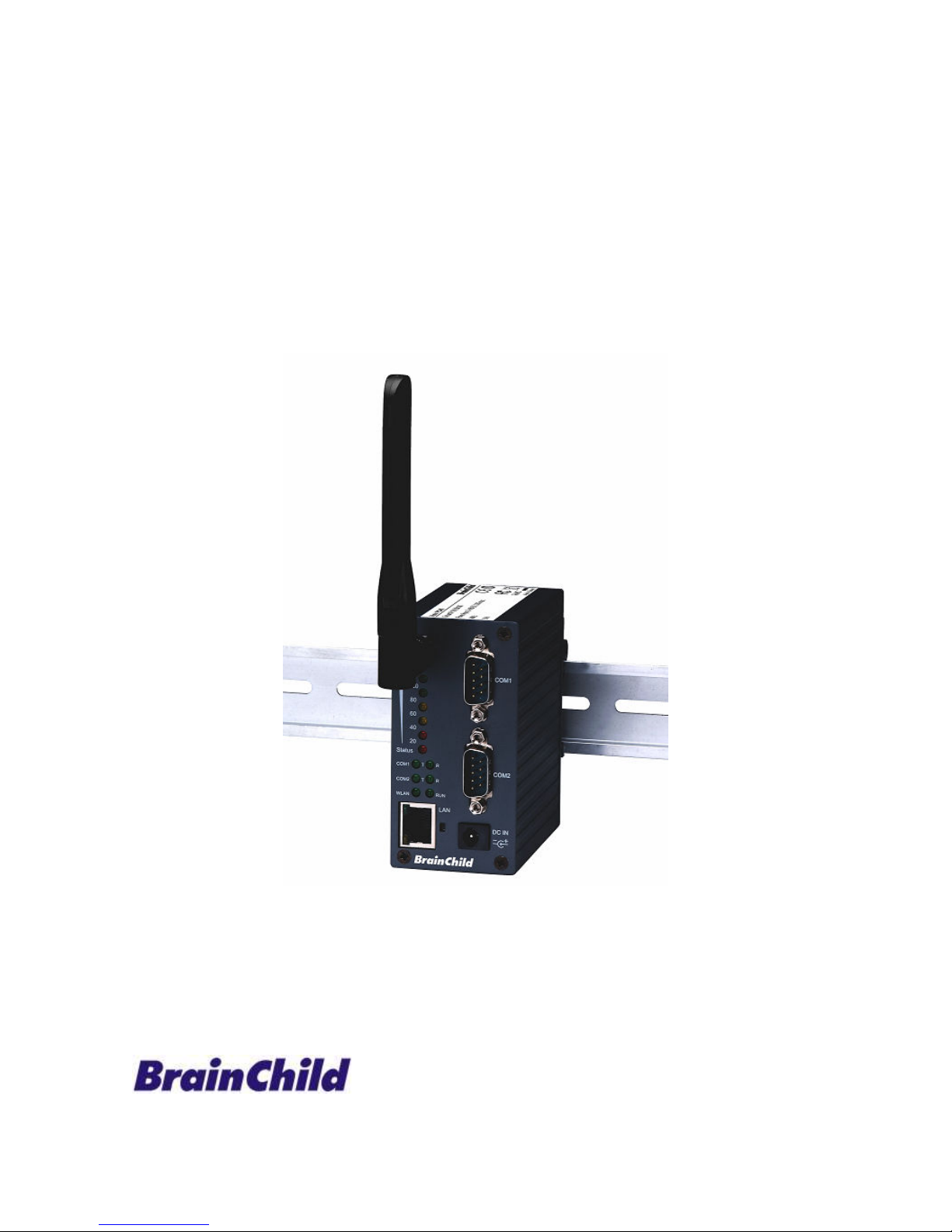
Ethernet to Wireless Client
Adaptor, PC-W
Brainchild Electronic Co., Ltd.
UMPCWA, 06/2009
Page 2

2
Important Announcement
The information contained in this document is the property of Brainchild Electronic and is supplied for the
sole purpose of operation and maintenance of products of Brainchild Electronic. No part of this publication
is to be used for any other purposes, and it is not to be reproduced, copied, disclosed, transmitted, stored
in a retrieval system, or translated into any human or computer language, in any form, by any means, in
whole or in part, without the prior explicit written consent of Brainchild Electronic
Brainchild Electronic Co. Ltd
6F, No.209, Chung Yang Rd, Nankang Dist
Taipei, Taiwan, R.O.C
Tel: 886-2-27861299, Fax: 886-2-27861395
Email: [email protected]
Website: http://www.brainchild.com.tw
Copyright © 2009 Brainchild Electronic. All rights reserved
All other product names referenced herein are registered trademarks of their respective companies.
Page 3

3
FCC WARNING
Class A for this product
This product has been tested and found to comply with the limits for a Class A digital device, pursuant to
Part 15 of the FCC Rules. These limits are designed to provide reasonable protection against harmful
interference in a residential installation. This equipment generates uses and can radiate radio frequency
energy and, if not installed and used in accordance with the instructions, may cause harmful interference
to radio communications. However, there is no guarantee that interference will not occur in a particular
installation. If this equipment does cause harmful interference to radio or television reception, which can
be determined by turning the equipment off and on, the user is encouraged to try to correct the
interference by one of the following measures:
Reorient or relocate the receiving antenna.
Increase the separation between the equipment and receiver.
Connect the equipment into an outlet on a circuit different from that to which the receiver is
connected.
Consult the dealer or an experienced radio/TV technician for help.
This product complies with Part 15 of the FCC Rules. Operation is subject to the following two conditions:
(1) This device may not cause harmful interference, and (2) this device must accept any interference
received, including interference that may cause undesired operation.
FCC Caution: Any changes or modifications not expressly approved by the party responsible for
compliance could void the user's authority to operate this equipment.
IMPORTANT NOTE:
FCC Radiation Exposure Statement:
This product complies with FCC radiation exposure limits set forth for an uncontrolled environment. This
model should be installed and operated with minimum distance 20cm between the radiator & your body.
This transmitter must not be co-located or operating in conjunction with any other antenna or transmitter.
IEEE 802.11b/g operation of this product in the U.S.A. is firmware-limited to channels 1 through 11.
UL Notice for Power supplier
All the series of PC-W products are intended to be supplied by a Listed Power Unit marked with “LPS”,
“Limited Power Source” or “Class 2” and output rate 9~48VDC, 1.0A minimum. Or, use the recommended
power supply in “Optional Accessories”.
Page 4

4
Contents
1. INTRODUCTION ............................................................................................................................................... 6
1.1. O
VERVIEW
...................................................................................................................................................... 6
1.2. F
EATURES
....................................................................................................................................................... 6
2. GETTING STARTED ......................................................................................................................................... 7
2.1. P
ACKAGING INCLUDE
..................................................................................................................................... 7
2.2. O
RDERING INFORMATION
............................................................................................................................... 7
2.3. I
NTERFACES
.................................................................................................................................................... 7
2.4. I
NSTALLATION PROCEDURES
.......................................................................................................................... 8
3. SOFTWARE SETUP ........................................................................................................................................... 8
3.1. D
EFAULT SETTINGS
........................................................................................................................................ 8
3.2. IP A
SSIGNMENT
.............................................................................................................................................. 9
3.2.1. Configure IP by Serial Manager Utility .....................................................................................9
3.2.2. Configure IP address using ARP commands...........................................................................9
3.2.3. Configure IP Using Web Interface..........................................................................................10
3.2.4. Automatic IP address assignment using DHCP.....................................................................10
3.3. TCP/IP P
ORT NUMBER
................................................................................................................................. 10
4. APPLICATION CONNECTIVITY ................................................................................................................. 11
4.1. TCP & UDP P
ROTOCOLS
.............................................................................................................................. 11
4.1.1. Transmission Control Protocol (TCP) ....................................................................................11
4.1.2. User Datagram Protocol (UDP) .............................................................................................11
4.2. C
ONNECTIVITY TOPOLOGY
........................................................................................................................... 11
4.3. E
THERNET TO
WLAN B
RIDGE FUNCTION
.................................................................................................... 12
4.4. V
IRTUAL
COM M
ODE
.................................................................................................................................. 12
4.4.1. TCP Server in Virtual COM Mode ..........................................................................................12
4.4.2. TCP Client in Virtual COM Mode ...........................................................................................12
4.5. T
UNNELING MODE
....................................................................................................................................... 13
4.6. UDP
MODE
................................................................................................................................................... 14
5. CONFIGURE PC-W BY WEB INTERFACE................................................................................................. 16
5.1. L
OGIN TO SYSTEM
........................................................................................................................................ 16
5.2. G
ENERAL INFORMATION
............................................................................................................................... 16
5.2.1. Device Information .................................................................................................................18
5.2.2. Wireless Client Adaptor Information ......................................................................................18
5.2.3. Serial Information ...................................................................................................................19
5.3. N
ETWORK CONFIGURATIONS
........................................................................................................................ 19
5.3.1. Wireless Client Adaptor Settings............................................................................................20
5.3.2. DNS Settings..........................................................................................................................21
5.3.3. SNMP Settings.......................................................................................................................21
5.4. W
IRELESS CONFIGURATION
.......................................................................................................................... 22
5.4.1. Wireless Settings ...................................................................................................................23
5.4.2. Sample Wireless Application Cases ......................................................................................23
5.5. COM P
ORT CONFIGURATION
........................................................................................................................ 25
5.5.1. TCP Server Mode ..................................................................................................................25
Page 5

5
5.5.2. TCP Client Mode....................................................................................................................25
5.5.3. UDP Mode..............................................................................................................................27
5.5.4. Serial Settings ........................................................................................................................27
5.5.5. Packet delimiter......................................................................................................................28
5.6. C
ONFIGURE SYSTEM
..................................................................................................................................... 28
5.6.1. Configure Time by NTP Service.............................................................................................28
5.6.2. WLAN Region ........................................................................................................................29
5.6.3. Security (Password Change) .................................................................................................29
5.6.4. Restoring Factory Default Configurations ..............................................................................30
5.6.5. Restart System.......................................................................................................................30
5.7. A
PPLICATIONS
.............................................................................................................................................. 31
5.7.1. Paperless Recorder VR18 (Ethernet port) to Wireless Ethernet ...........................................31
5.7.2. Paperless Recorder VR18 (Serial port) to Wireless Ethernet................................................37
5.7.3. Paperless Recorder VR18 to PC via Wireless Ethernet (Using 2 PC-W devices) ................46
APPENDIX A. USING VIRTUAL COM ........................................................................................................... 48
A.1. PRE-
INSTALLATION REQUIREMENTS
............................................................................................................. 48
A.2. L
IMITATION AND INSTALLATION
................................................................................................................... 48
A.3. V
IRTUAL
COM C
OMMUNICATION
................................................................................................................ 49
APPENDIX B. CONFIGURATION UTILITY ................................................................................................. 52
B.1. S
ERIAL MANAGER UTILITY INTRODUCTION
.................................................................................................. 52
B.2. I
NTERFACE
.................................................................................................................................................... 52
B.3. F
UNCTIONS
................................................................................................................................................... 52
B.3.1. Device Search........................................................................................................................52
B.3.2. Firmware ................................................................................................................................54
B.3.3. Configuration..........................................................................................................................56
B.3.4. Security ..................................................................................................................................57
B.3.5. View........................................................................................................................................58
B.3.6. About......................................................................................................................................58
APPENDIX C. UPGRADING SYSTEM SOFTWARE .................................................................................... 58
APPENDIX D. SPECIFICATIONS.................................................................................................................... 59
D.1. H
ARDWARE SPECIFICATIONS
........................................................................................................................ 59
D.2. S
OFTWARE SPECIFICATIONS
.......................................................................................................................... 60
D.3. P
IN ASSIGNMENTS
........................................................................................................................................ 60
D.3.1. DB9 male connector pin assignments for Serial port.............................................................60
D.4. B
EEP &
LED S
TATUS
.................................................................................................................................... 60
D.4.1. Startup status .........................................................................................................................60
D.4.2. Wireless Signal Strength status .............................................................................................61
D.4.3. WLAN LED Message .............................................................................................................61
D.4.4. COM Port LED Message .......................................................................................................61
D.4.5. RUN LED Message................................................................................................................61
Page 6
6
1. Introduction
1.1. Overview
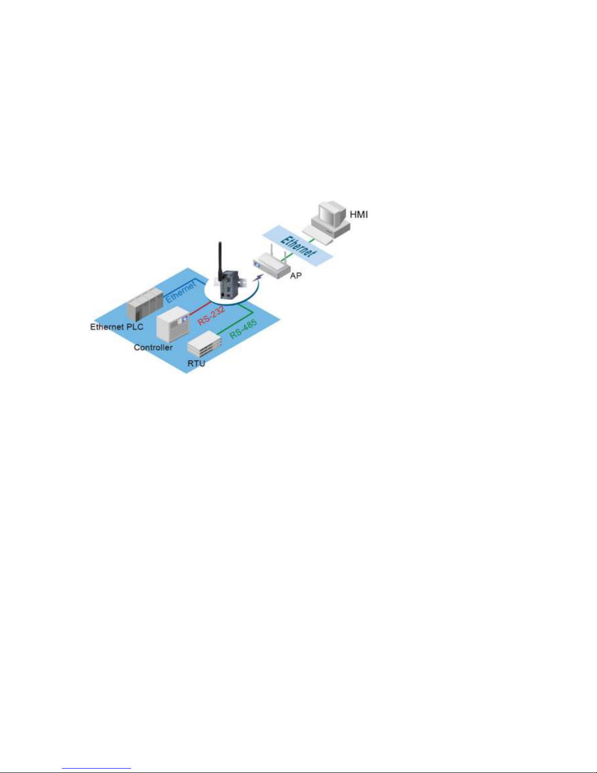
PC-W Wireless Client Adaptor is a bridge between RS-232, RS422, RS-485, Ethernet based devices and
wireless LAN. It allows almost any Ethernet and serial devices to be connected to a new or existing wireless
network. The information transmitted by Wireless Client Adaptor is transparent to both host computers (IP
network over wireless LAN) and devices (Ethernet/RS-232/RS-422/ RS-485). Data from the wireless LAN is
transmitted to the designated Ethernet/ RS-232/ RS-422/ RS-485 port and data from Ethernet/ RS-232/
RS-422/ RS-485 port is transmitted to the Wireless (TCP/IP) transparently.
In the computer integration manufacturing or industrial automation area, Wireless Client Adaptor is used for
field devices to direct connect to network.
Many control devices provide the ability to communicate with hosts through Ethernet/RS-232/RS-485
however RS-232/RS-485 serial communication has its limitations. For instance, it is hard to transfer data
through Wireless or long distance. With PC-W, it is possible to communicate with a remote device in the
Intranet environment and thus, increases the communication distance dramatically.
Flexible configuration options enable this unit to be setup remotely over IP network by Web browser, or
Window utility. Packed in a rugged DIN Rail mountable case and 9~48V DC power input range, PC-W is
ideal for almost any industrial and manufacturing automation.
1.2. Features
Features
2 Nos. serial ports
Selectable RS-232/RS-485/RS-422 serial mode by software
Transparent between Ethernet to Wireless networking
Support UDP, TCP server and client protocols for Virtual COM mode and pair connection
Configurable via built-in web server and Windows-based utilities
Metal housing and IP50 standard with DIN-Rail mounting.
15KV ESD protection for serial ports
IEEE 802.11g 54Mbps wireless network connectivity
Standard 2.4GHz High-gain antenna
Page 7
7
2. Getting Started
2.1. Packaging Include
PC-W Wireless Client Adaptor x 1
4 dBi Antenna x 1
Wall mount kits x 2
PC-W Wireless Client Adaptor quick start guide x 1
Product CD containing configuration utility x 1
NOTE: Notify your sales representative if any of the above items is missing or damaged.
2.2. Ordering information
The PC-W can be ordered using the following codes.
PC-W
Wireless Client Adaptor plus 2-ports with D-Sub 9pin serial
connector
Optional Accessories and their ordering codes
AH1812-B
AH1812-E
1GP-2409
1PG-24001
1CB-0025
AC100~240V US plug / DC12V DC – Jack, Power adapter
AC100~240V EU plug / DC12V DC- Jack, Power adapter
9.0 dBi Omni directional antenna,
N female connector (Max. line of sight distance: 800 mtr)
9.0 dBi directional panel antenna
External RF Cable, RG58 SMA to N Male 3 m to be used with antenna
2.3. Interfaces
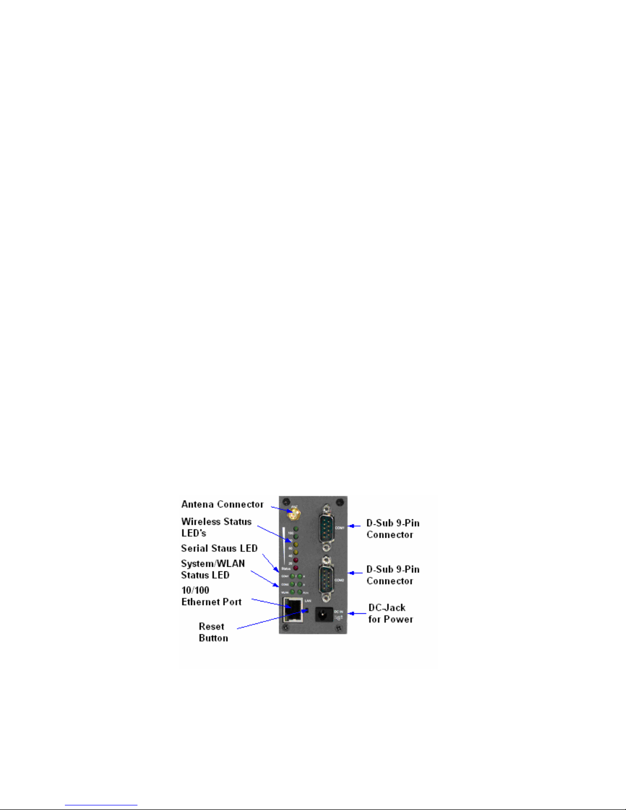
The interfaces of PC-W on the front panel are shown in Fig. 1.
DB Model (9 pin D-Sub Connectors)
Fig. 1. PC-W Front Panel and Interfaces
Page 8

8
2.4. Installation Procedures
Prepare necessary cables, DC power adaptor and RS-232/RS-485 connector.
Install Serial Manager software in your PC from Product CD
Place PC-W under the access point signal coverage area. Connect PC-W to your PC via Ethernet
using RJ45 connector.
If you wish to connect serial device to PC-W, connect it. Please make sure the connector and
wiring of RS-232 or RS422 or RS-485 is correct. If you just wish to connect Ethernet device to
PC-W, then first complete checking of PC-W status from Computer, then connect Ethernet device
to PC-W
Plug in PC-W to DC-9-48V power source (with DC-jack), buzzer will beep and the RUN LED will
blink if PC-W functions normally. For LED Status see Appendix D.4
Use Serial Manager, configuration utility to check the status of PC-W. If it starts up successfully, users shall
find the IP and MAC addresses of PC-W. Users can also change IP address, gateway IP address and
subnet mask networking parameters of PC-W according to user networking configurations.
3. Software Setup
Now the PC-W hardware is installed and the power is on, network IP configuration will be set in this section.
3.1. Default Settings
The PC-W has two IP addresses one for Ethernet interface and another one for
wireless network interface. These default settings are shown below
Property Default Value
Wireless Client Adaptor IP
IP Address 10.0.50.100
Gateway 10.0.0.254
Subnet Mask 255.255.0.0
Security
User Name Admin
Password Null (Leave it blank)
Serial
COM 9600/None/ 8/1,No flow control, packet delimiter disabled
Link Mode TCP Server, Listen port 4660/4661,No Filter, Virtual COM disabled
SNMP
SysName of SNMP Name
SysLocation of SNMP Location
SysContact of SNMP Contact
Table 1. Factory default settings of the PC-W
Reset procedure: Push Reset button for 5 seconds and then release to restart PC-W with the
factory default settings.
Warning: Please avoid setting LAN and WLAN IP addresses in the same subnet. This may create
unexpected networking problems.
Page 9
9
3.2. IP Assignment
3.2.1. Configure IP by Serial Manager Utility
Use Serial Manager, configuration utility that comes with Product CD-ROM to configure the network
parameters. For more details, please refer to Appendix B1.
Find a new device and IP assignment
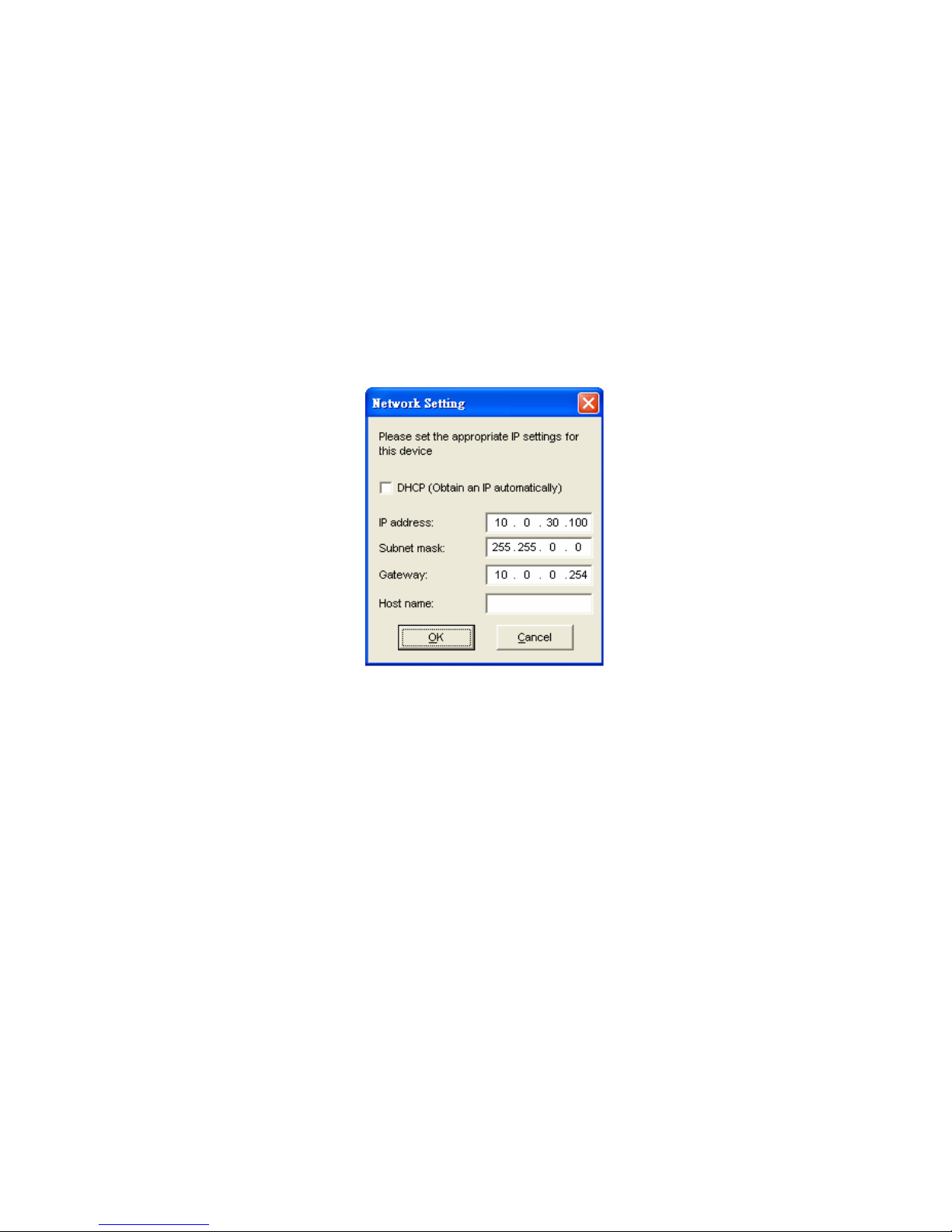
Use Serial Manager Utility to find the new device IP address or to get the device’s current IP
address as shown in Fig. 2.
If needed, use Serial Manager Utility to re-assign a new IP address, Network Mask and Gateway
address to the new device.
Users can also configure User ID, Password and Host Name using Serial Manager Utility.
Fig. 2. IP Settings using Serial Manager Utility software
Note: All settings will NOT be changed if User ID or Password was incorrect.
If there is more than one device using the same IP address in the same subnet, users need to correct the
mapping between MAC address and IP address using ARP commands as explained in the next section.
3.2.2. Configure IP address using ARP commands
ARP (Address Resolution Protocol) commands can be used to assign a static IP address on PC-W using its
hardware MAC (Media Access Control) address. The MAC address "0060E9-xxxxxx" is printed on the rear
side of PC-W. The following procedure show how to use ARP commands on MS-DOS Command Prompt
Window
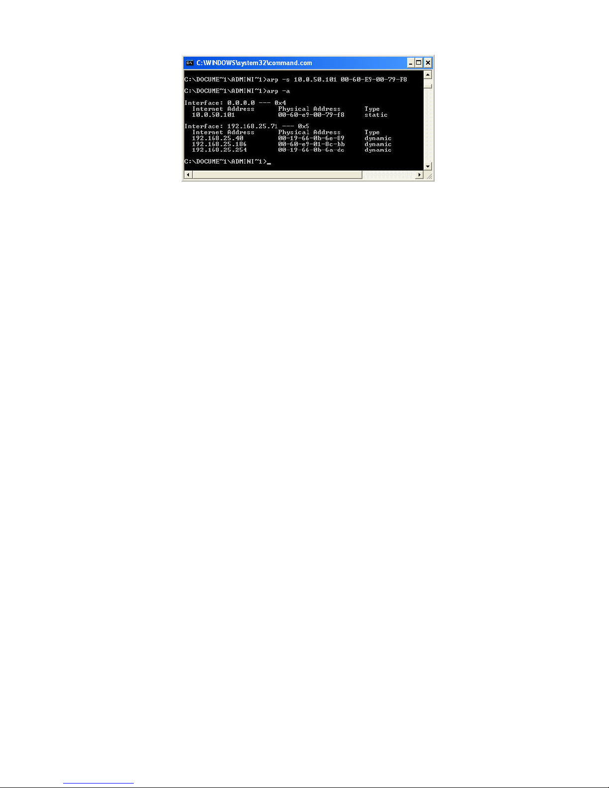
Example: Set the IP address 10.0.50.101 to the MAC address 00-60-E9-00-79-F8
C:\> arp –s 10.0.50.101 00-60-E9-00-79-F8
arp –a command shows the current mapping IP and MAC addresses
arp –s “IP address” “MAC address” maps the IP address to a specific MAC address
Note: ARP commands can only be used to set a static IP address of PC-W
Page 10
10
Fig. 3. Mapping IP address to MAC address using ARP Command
3.2.3. Configure IP Using Web Interface
Use common web browsers, e.g. Microsoft Internet Explorer or Mozilla Firefox, to configure the network
parameters of PC-W.
Open a Web browser, type in the IP address (default IP: 10.0.50.100) of the PC-W to be
configured. The default user name is admin and the default password is null (leave it blank).
From the Web Network links page, please configure IP address, subnet mask, and gateway
address, and then click “Save Configuration” to save all settings.
Click Restart button to reboot the device to make the changes effective.
Please refer to contents of Web Configuration section for more details of the settings.
3.2.4. Automatic IP address assignment using DHCP
DHCP server can automatically supply an IP address, gateway address, and subnet mask to PC-W device
if its DHCP client function is enabled. By default, the DHCP client function is disabled, users can activate
the DHCP function by following these steps
Execute Serial Manager Utility
Click on the IP address of PC-W (This can be the default IP address if it was never set before).
Click Config to pop-up the static IP Dialog Window.
Check on Auto IP
Click Config Now. (The PC-W will restart and obtain an IP from DHCP server automatically)
Note: You need to have a DHCP Server running in your subnet to automatically supply an IP
address. Please consult your network administrator if you are not sure.
3.3. TCP/IP Port Number
Default TCP Port numbers of PC-W are 4660 (1st port) and 4661 (2nd Port) that are associated with the
Serial port COM1 and COM2, respectively. After the application program connects to the TCP port 4660
(or 4661) on the PC-W, data of user’s application program are transparently transmitted to Serial port
COM1 (or COM2) of PC-W.
Page 11

11
4. Application Connectivity
The PC-W is designed to transmit data between one or more Ethernet/serial devices to/from one or more
TCP/IP devices through wireless Ethernet interface. PC-W can enhance the accessibility of the serial
device through TCP/IP based Ethernet as well as Wireless Ethernet. The connection distance limit is
overcome by PC-W. Examples of these devices are PLC controllers, card readers, display signs, security
controls, CNC controller, etc.
4.1. TCP & UDP Protocols
PC-W can operate in two most common transportation protocols, TCP and UDP.
4.1.1. Transmission Control Protocol (TCP)
TCP provides a connection and a byte oriented data stream with control parameters such as flow control,
multiple ports option, and order delivery notification. Once the connection is established, data can be
transmitted in both directions. TCP guarantees data is transmitted from one node to the other node(s) in
orderly. The protocol also distinguishes the transmitted data for different applications (such as a Web server
or an Email server) on the same computer.
For redundant or dual-network connectivity purposes, PC-W offers two TCP operation modes so users may
choose for their specific application, TCP Server Mode and TCP Client Mode.
4.1.2. User Datagram Protocol (UDP)
UDP is a faster datagram delivery protocol. User can configure PC-W to work in the UDP mode. UDP is
connectionless protocol and can transmit multicast data to/from a serial device to one/multiple host
computer. Because UDP is the connectionless protocol, UDP does not guarantee the reliability and orderly
data streams like TCP protocol. Datagram may arrive out of order or lose without notice. But the advantage
of UDP is the speed. UDP is faster and hence more attractive in time-sensitive applications.
4.2. Connectivity Topology
PC-W is also equipped with Tunneling and Virtual COM operation modes. It is designed to transmit data
to/from multiple serial devices and from/to multiple TCP/IP devices on Ethernet, so it can enhance the
accessibility of the serial devices immensely. The example of PC-W connection topology is shown in Fig. 4.
Note: Please do not connect more then one device on Ethernet port
Fig. 4. Typical Topology of PC-W Connection
Page 12
12
4.3. Ethernet to WLAN Bridge Function
The PC-W can also work as a network bridge between Ethernet to WLAN. Packets from WLAN to Ethernet
or from Ethernet to WLAN are transferred transparently. This will let the Ethernet devices can be accessed
from wireless networks over the wireless interface.
4.4. Virtual COM Mode
The Virtual COM software emulates a serial port in LAN topology. In the Virtual COM Mode, COM port data
is encapsulated with Ethernet data format. By creating a virtual COM port on a PC, the Virtual COM driver
redirects communications from the virtual COM port to the destination IP address (and the designated port
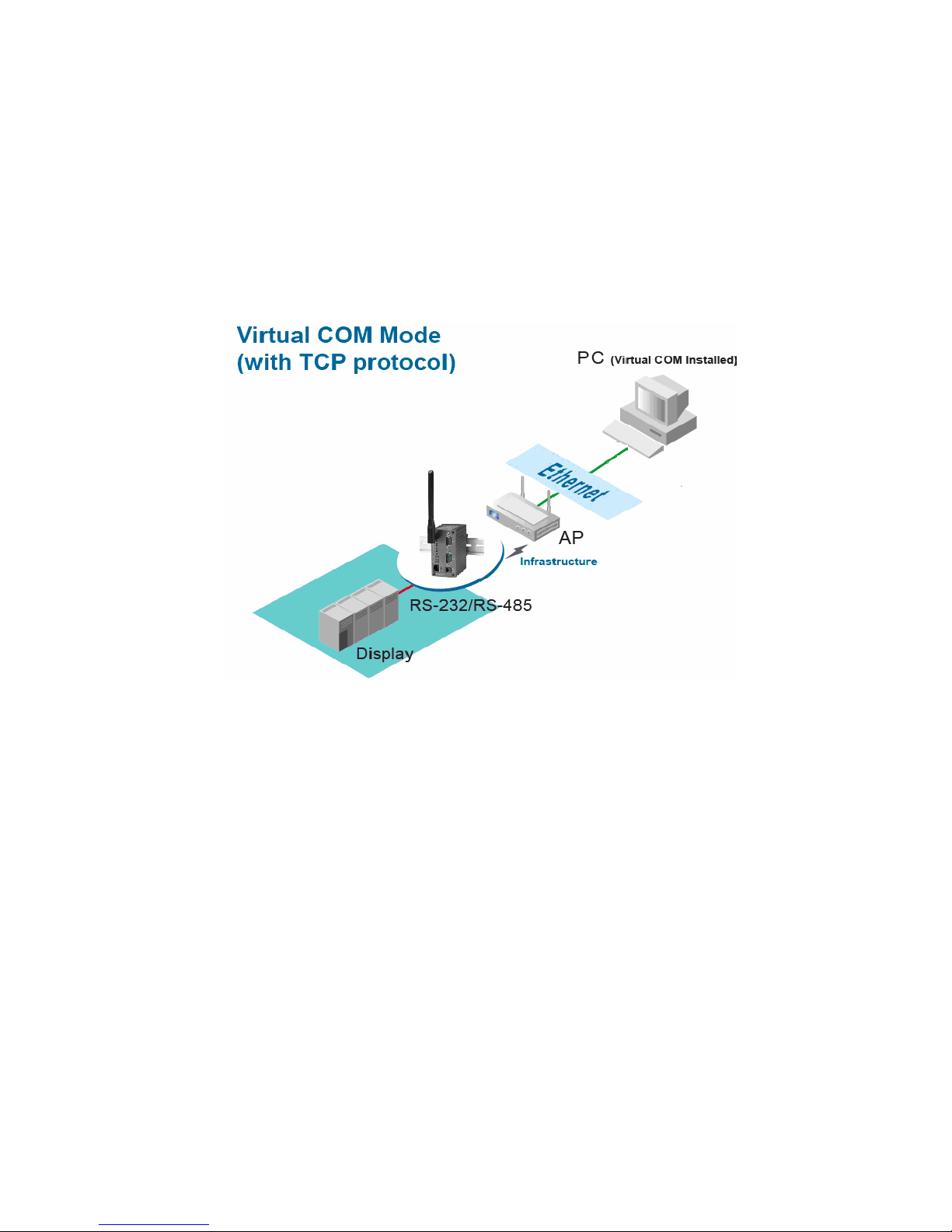
number) by encapsulating COM data into IP packet format. Fig. 5 illustrates a Virtual COM connection
diagram.
Fig. 5. TCP Connection in Virtual COM Mode
4.4.1. TCP Server in Virtual COM Mode
PC-W can be configured in the TCP server mode (PC acts as a client) with a unique IP and Port number,
and PC-W waits passively for the PC to establish a connection. After the connection is established, PC can
communicate to serial devices through PC-W.
Configure PC-W to be TCP server
Using one of the two configuration methods, by Web-based and by Windows-based Serial Manager utility,
Users can configure PC-W to be a TCP Server as follows.
Disabled the IP filter (default)
Set the port number (default port is 4660 for COM1, 4661 for COM2).
If IP filter is enabled, only the assigned source IP is allowed to be connected to PC-W.
4.4.2. TCP Client in Virtual COM Mode
PC-W can also be configured in TCP Client mode (PC as a server) to establish a TCP connection to an
application server on PC, or the Remote Control Host. Once the connection is established, PC or Remote
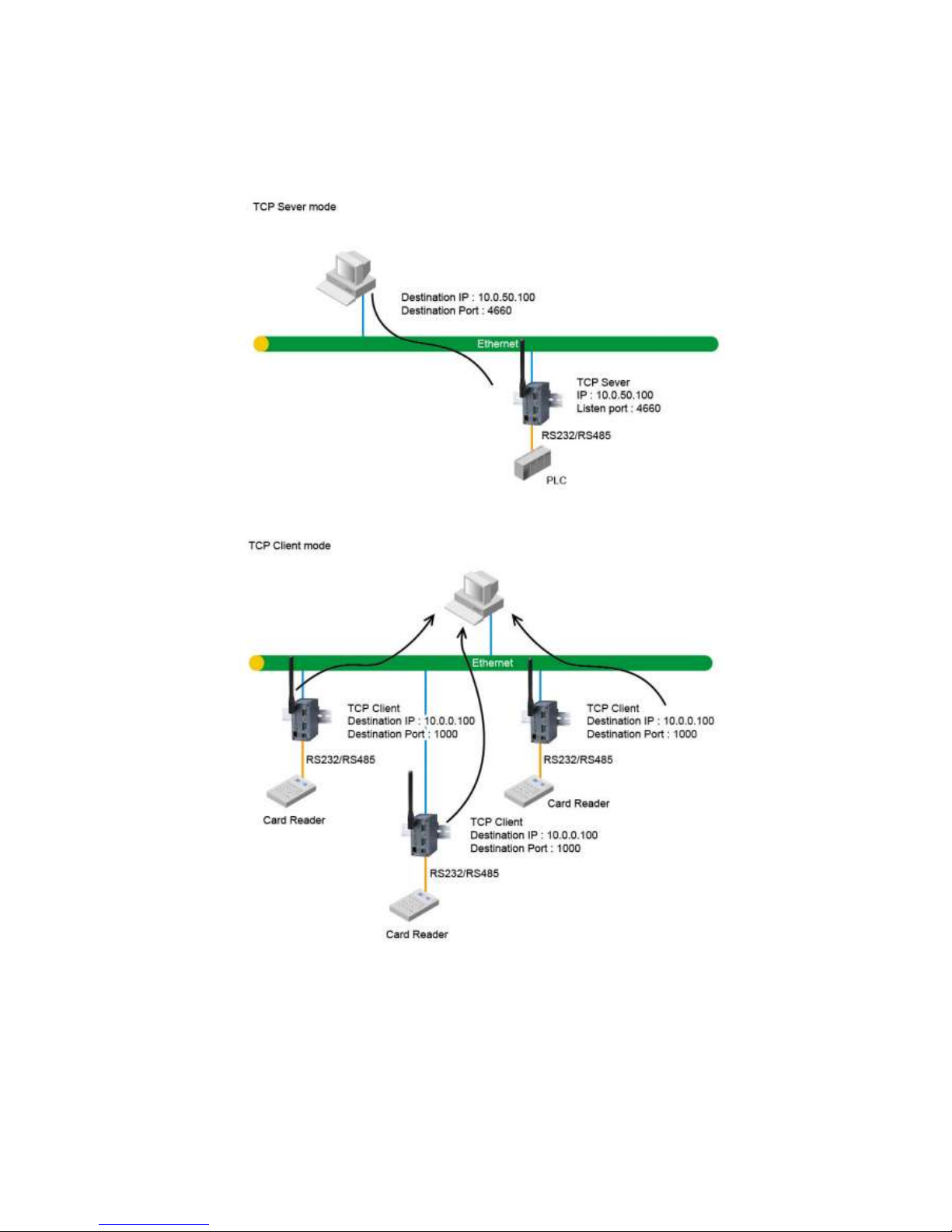
Control Host can exchange data with several serial devices at the same time through PC-W as shown in Fig.
6.
Page 13
13
Configuring PC-W to be TCP client
User can configure PC-W to be as a TCP client, for example, from Fig. 7, PC, as a server, has IP address
10.0.0.100 and listening on port 1000. Each PC-W, connected with serial device, configured as TCP client
mode with destination IP address 10.0.0.100 and the destination port 1000, and the IP filter is disabled (by
default).
Fig. 6. TCP Server in Virtual COM Mode
Fig. 7. TCP Client in Virtual COM Mode
4.5. Tunneling Mode
Tunneling Mode is used for multiple serial devices to “talk” among one another through PC-W’s wireless
LAN or wired Ethernet interface. This mode is particularly useful when two or more serial devices are far
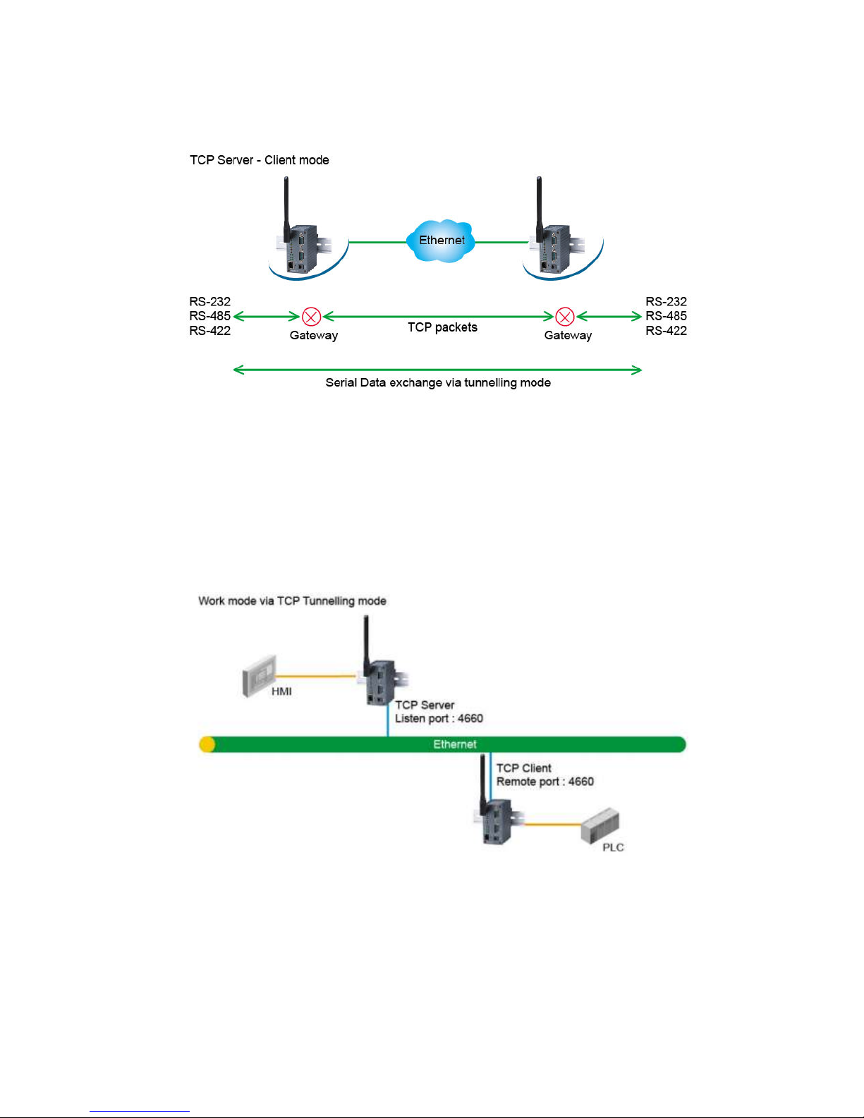
away. This mode can be used to extend the normal RS-232 serial communication distance of 15 m to 100 m
or longer as shown in Fig. 8.
Page 14
14
One PC-W can be configured to be the TCP Server Mode with serial device connected and also another
PC-W is configured as TCP client with serial device connected. After the connection is established, both
serial devices can exchange data to each other transparently. For example, users can implement PC-W
tunneling mode for Master /Slave mode PLC’s or between other serial devices.
Fig. 8. TCP Link in Tunneling mode
Configuring PC-W to Tunneling Mode
Using one of two configuration methods (Web-based or Windows-based Serial Manager utility), users can
configure PC-W to TCP Server mode with a desired IP address and port, and with other PC-W is configured
as TCP Clients mode with Server IP and port as destination IP and port respectively as shown as an
example in Fig. 9.
Note: TCP client has to assign the destination IP and the destination port corresponding to TCP
server’s IP and listening port (example: TCP 4660 port).
Fig. 9. TCP Tunneling Mode
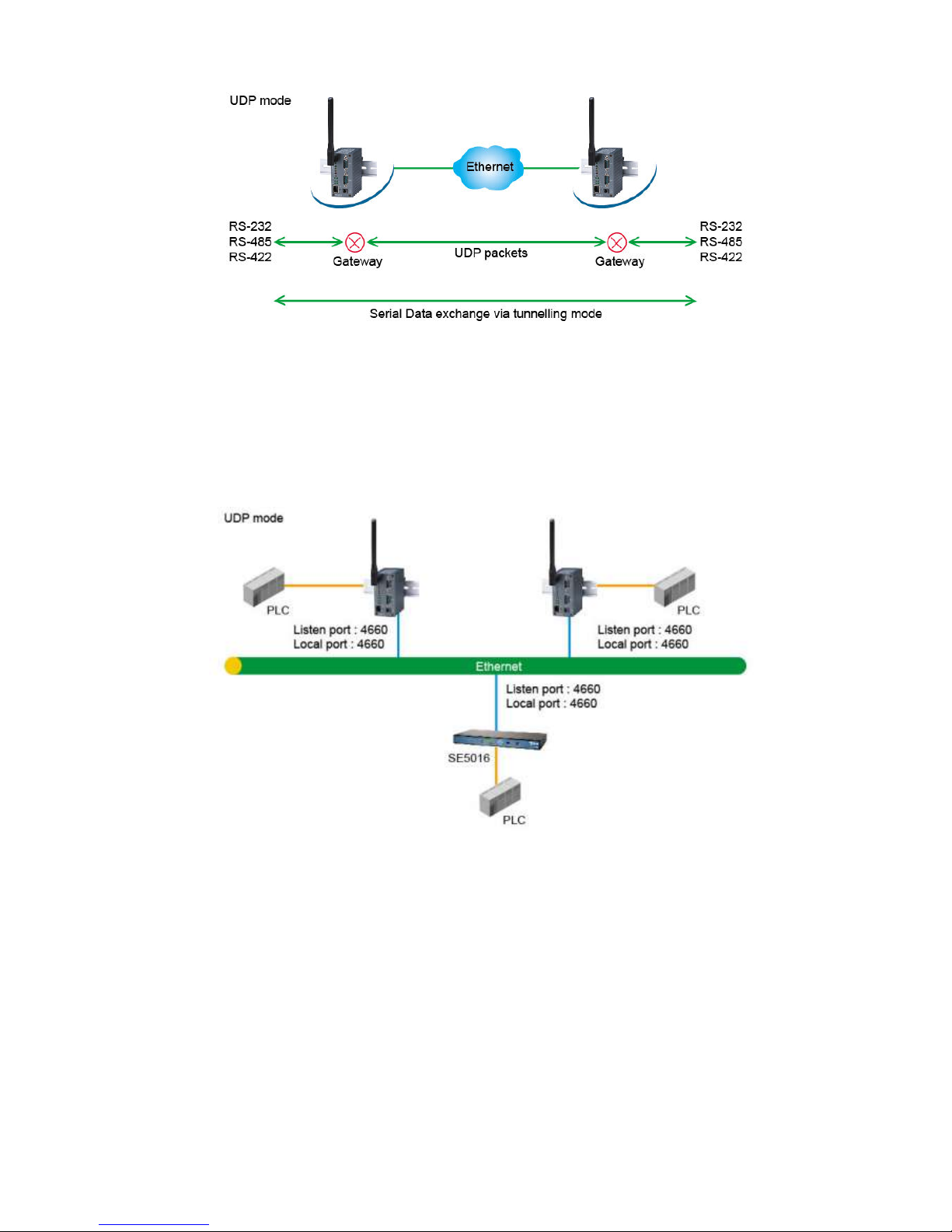
4.6. UDP mode
In UDP mode, users may exchange Multicast data from one PC-W with multiple PC-W devices as shown in
Fig. 10.
Page 15
15
Fig. 10. UDP Link in Tunneling mode
Configure PC-W in UDP Mode
Use one of the two configuration methods (Web-based or Windows-based Serial Manager Utility). Users
can configure PC-W to UDP mode. In UDP mode, PC-W can be configured to communicate to more than
one node (Multicasting). Note that the Multicast IP address is limited by the Class of IP address and subnet
mask. As an example, for a network of Class C of subnet 192.168.1.X and a subnet mask of 255.255.255.0,
the maximum Multicast IP address to be configured is four destinations IP’s.
Fig. 11. Multi-UDP Link in Tunneling Mode
Page 16
16
5. Configure PC-W by Web Interface
Users need to assign an IP address to PC-W before working on the web configuration operations. Please
refer to Section 3.2 for IP address assignment.
5.1. Login to System
Open one of the web browsers, ex. Microsoft IE or Firefox etc. Enter the IP address of PC-W on the URL.
Example: http://10.0.50.100 or http://your-device-IP-address.
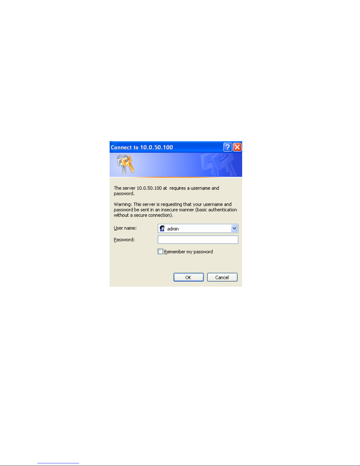
The following authentication screen shall appear. Enter User Name and Password then click on “OK”. The
default user name is “admin” and password is null (leave it blank).
Fig. 12. Authentication request for system security
5.2. General Information
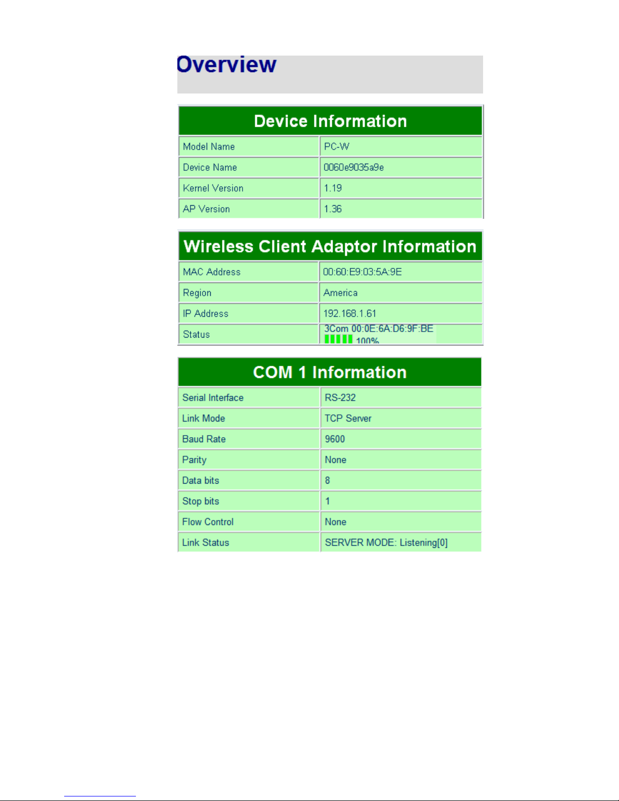
Once the login is successful, an Overview window gives the general information of PC-W, included Network,
and Serial information as shown in Fig. 13.
Page 17
17
Page 18
18
Fig. 13. Overview of system information on a Web Interface
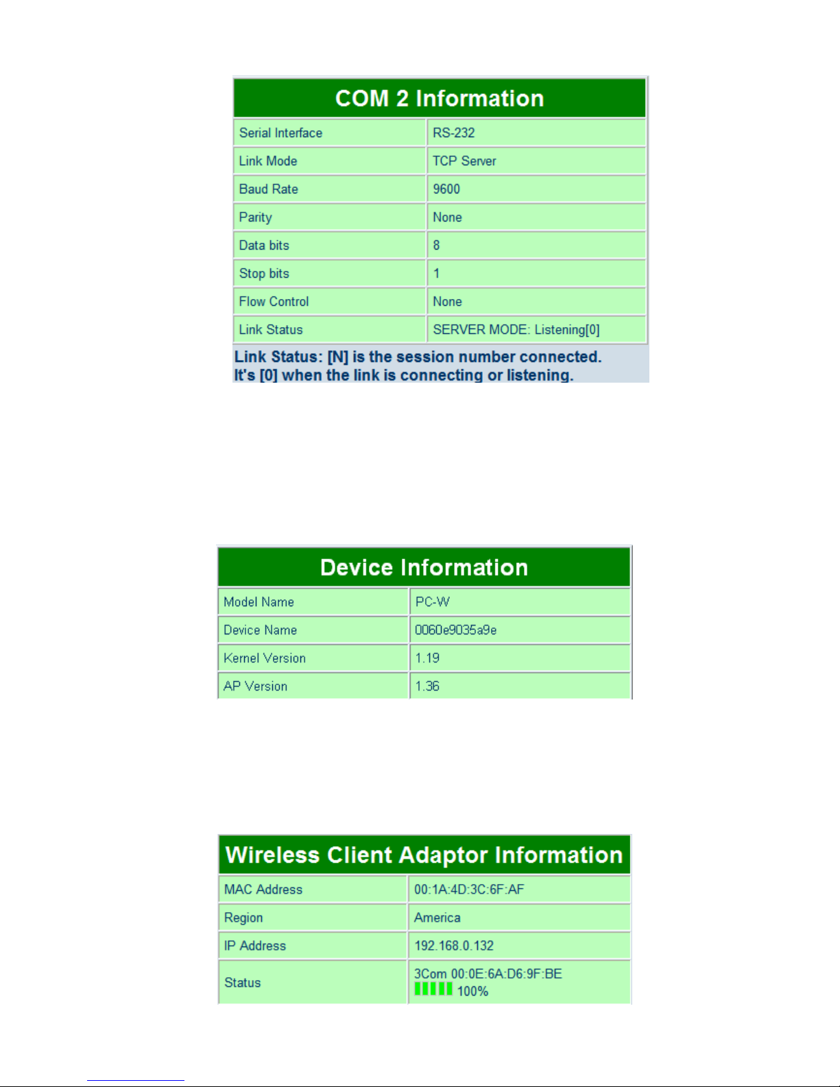
5.2.1. Device Information
PC-W’s system information includes Model Name, Device Name, Kernel Version, and AP version. The
information is read only and is attributed from setting page or system status.
Fig. 14. Device Information from Overview web page
5.2.2. Wireless Client Adaptor Information
Wireless Client Adaptor Information fields display both LAN & Wireless LAN (WLAN) information. The
information provided are LAN MAC address, Region for Regulation, LAN IP address, WLAN MAC address,
WLAN IP address, and Link status.
Page 19
19
Fig. 15. Wireless Client Adaptor Information from Overview web page
5.2.3. Serial Information
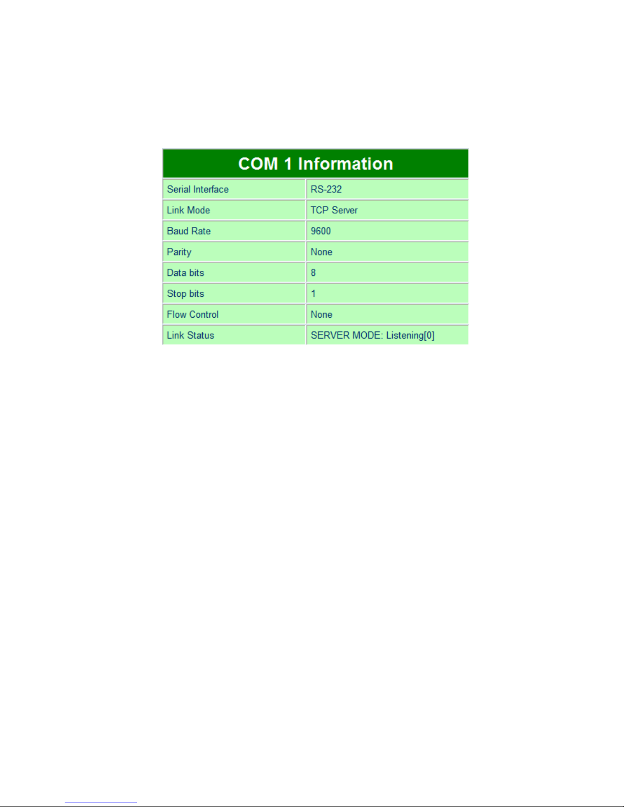
PC-W COM1 (COM2) information includes UART mode, link mode, baud rate, parity, data bits, stop bits,
flow control and link status. The COM1 (COM2) information is read only and is attributed from Serial
settings of COM1 or COM2 Port of PC-W.
Fig. 16. Serial Information from Overview web page
5.3. Network Configurations
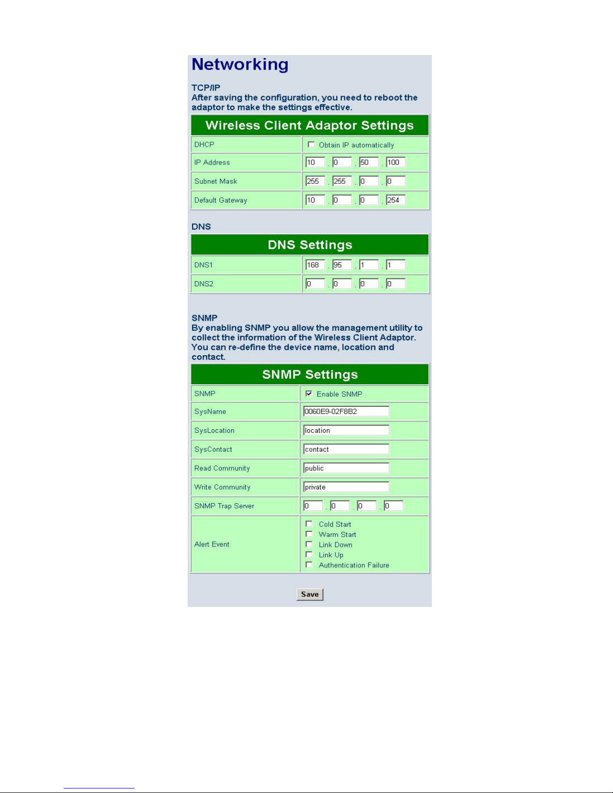
There are three items allowed to change on Networking page, included Wireless Client Adaptor Settings,
DNS Setting and SNMP Settings.
Page 20
20
Fig. 17. Network information by Web page
5.3.1. Wireless Client Adaptor Settings
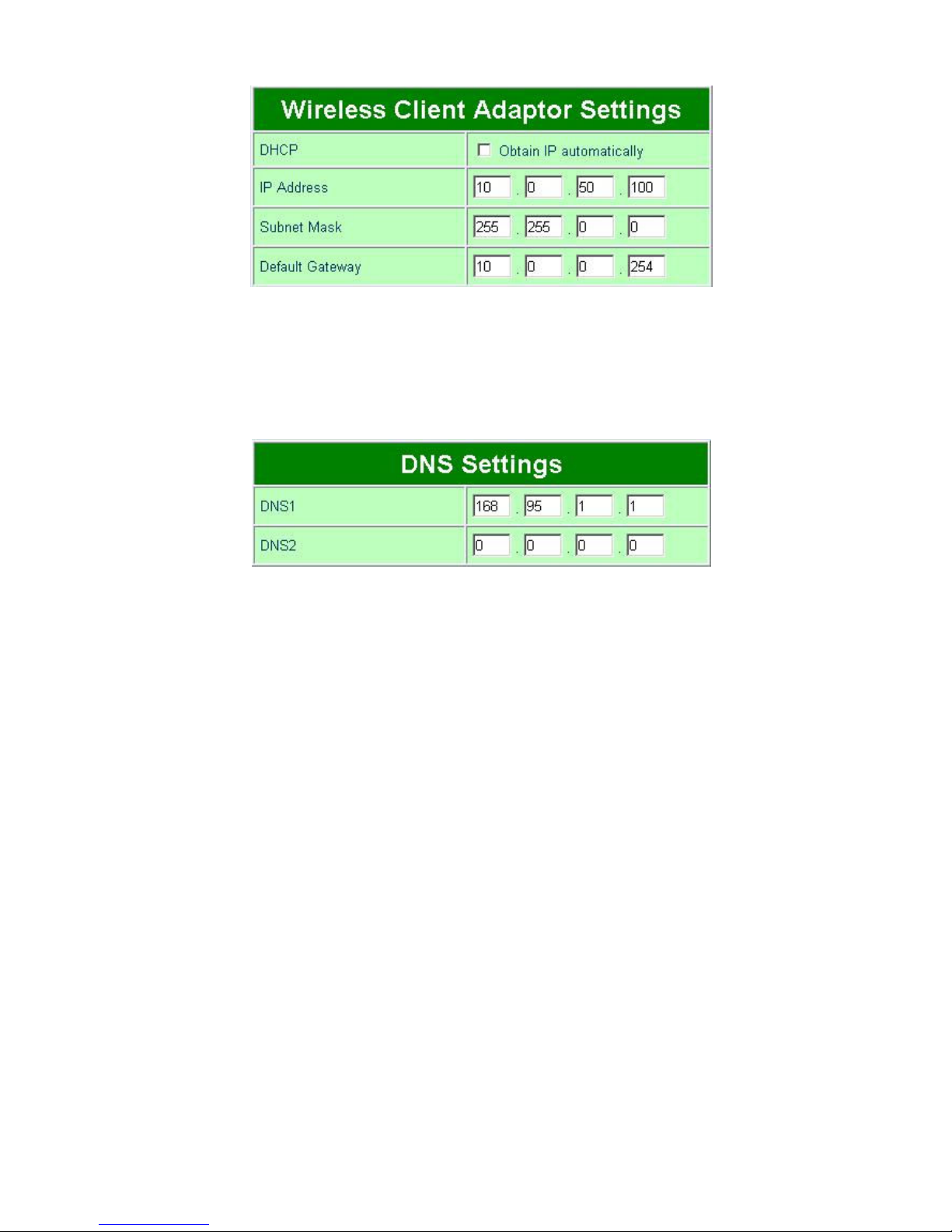
Click on the “Network” link and the following screen shall appear. Fill in network information on WLAN
interface including IP Address, Subnet Mask, and Default Gateway. Alternatively, User may activate DHCP
client function by checking on “Obtain an IP automatically” field to automatically obtain IP Address, Subnet
mask and Default gateway from a DHCP server.
Page 21
21
Fig. 18. Wireless Client Adaptor Settings from Network web page
5.3.2. DNS Settings
Click on the “Network” link and the following screen shall appear. Fill in the IP Address of DNS Servers in
DNS1 and DNS2 fields. Alternatively, User can configure DNS by checking on “Obtain an IP automatically”
field in LAN Settings or WLAN Settings fields to automatically obtain DNS from a DHCP server.
Fig. 19. DNS Settings from Network web page
5.3.3. SNMP Settings
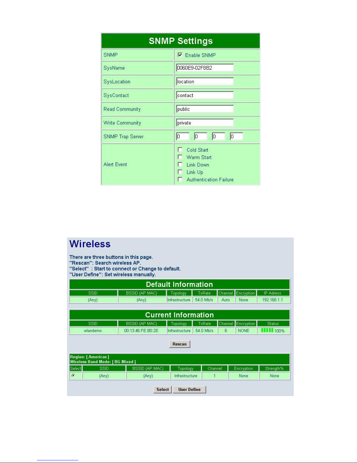
Click on the “Network” link and the following screen shall appear. Check on “Enable SNMP” checkbox to
continue the setting. Fill in the desired SysName, SysLocation, SysContact information in the fields. To give
permission to read/write SNMP information, fill in the “Read Community” and “Write Community”. To set up
a trap, fill in the IP address of a SNMP Trap Server, and then select events on which the trap server will
catch. The changes of SNMP Settings will take effect only after the PC-W is restarted.
Page 22
22
Fig. 20. SNMP Setting from Network web page
5.4. Wireless Configuration
There are three configuration pages for Wireless Configuration which are Default, Current and Site-Survey
Information Pages. Click on “Wireless” link and the following screen shall appear.
Fig. 21. Wireless Interface Information by Web page
There are 3 buttons can be operated on the Wireless page
Page 23
23
Rescan: Click on the “Rescan” button, and PC-W will start site-survey procedures, then on the
site-survey list will display the access points founded.
Select: On the site-survey list, click on radio button to attach to the access point you wanted.
User defined: Users can also define information of wireless access point to be manually
connected.
5.4.1. Wireless Settings
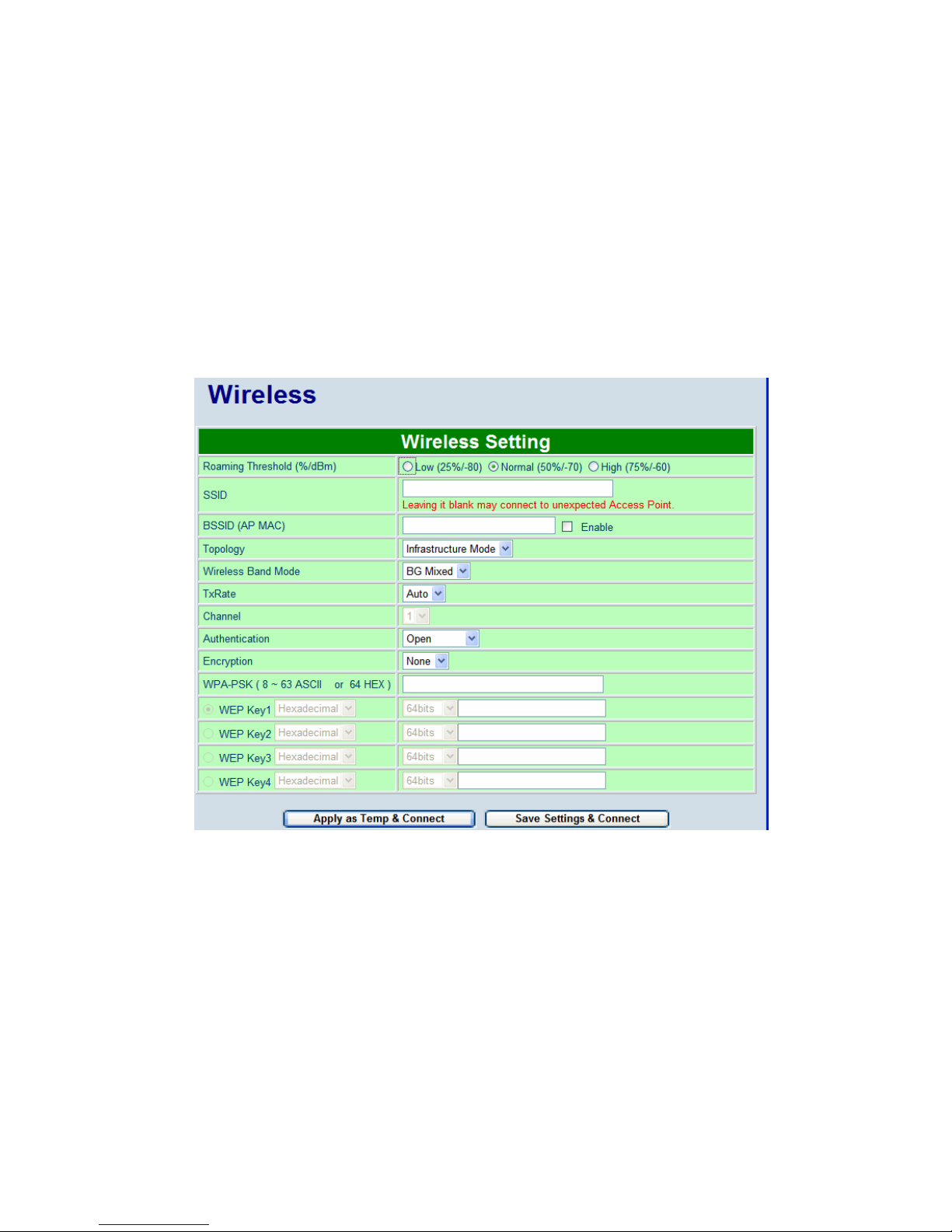
Users can configure wireless LAN parameters through web pages. Pop-up windows page will be shown for
advanced wireless settings if “Select” or “User Define” button was clicked. For example, User can configure
SSID, BSSID, Topology, Wireless Band Mode, TxRate, Channel, Authentication, and Encryption of the
access point that PC-W want to connect to.
The advanced wireless settings also include Roaming Threshold. User can configure roaming signal
threshold. PC-W will change to the stronger signal wireless access point, if the original access point’s signal
strength is less than the roaming threshold.
Fig. 22. Pop-up Windows for Wireless Settings
5.4.2. Sample Wireless Application Cases
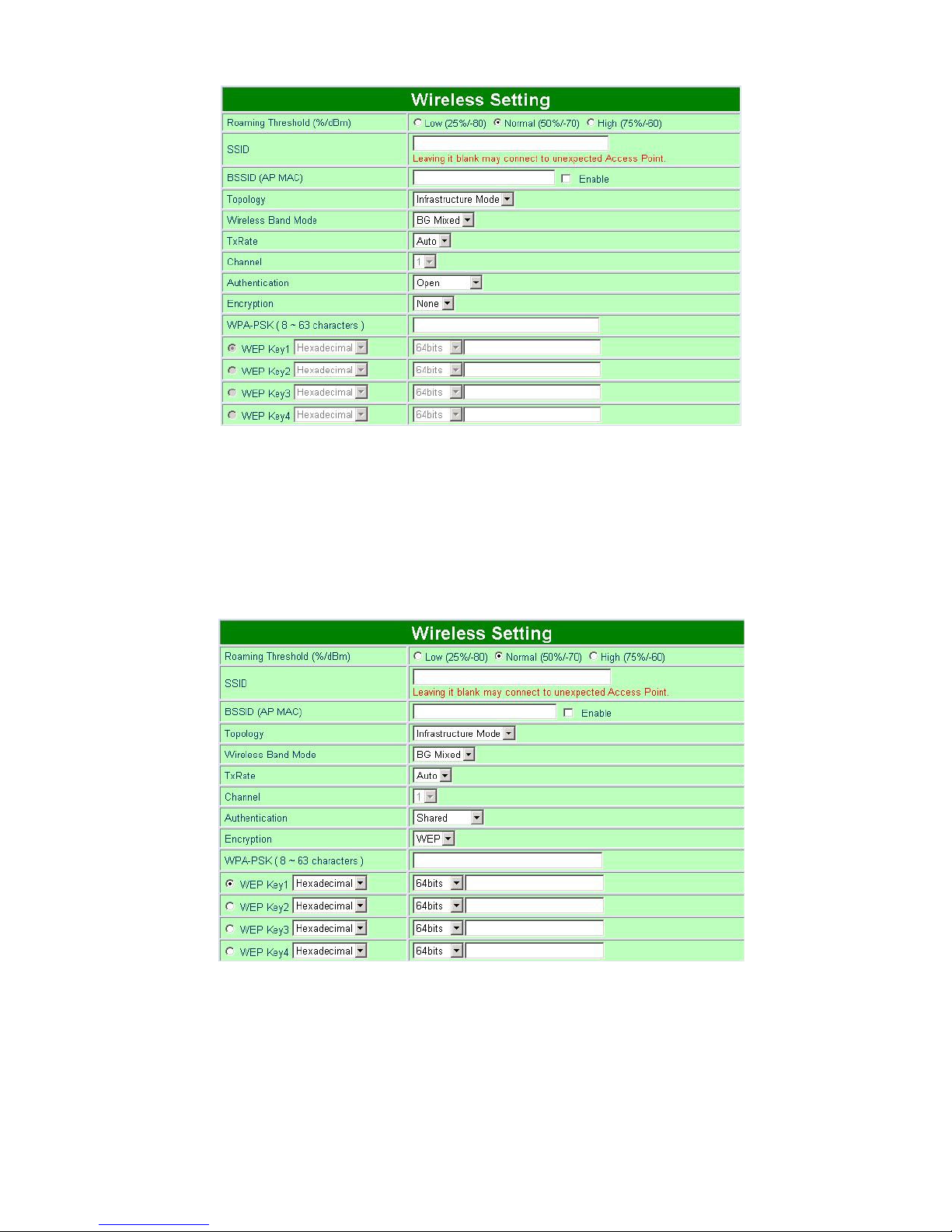
Below are some screen shot examples of Wireless Settings for different wireless security schemes.
I. Attach to the access point without authentication
Topology: Infrastructure Mode
Channel: Auto-assignment from Access point
Authentication: Open
Encryption: None
Page 24
24
Fig. 23. Open Authorization and no Encryption
II. Attach to the access point with WEP Encryption
Topology: Infrastructure
Channel: Auto-assignment from Access point
Authentication: Shared
Encryption: WEP
WEP Key1~4: Hexadecimal or ASCII, 64 or 128bit, <WEP Key>
Fig. 24. Share Authorization and WEP Encryption
Note1: Enter 5 ASCII value or 10 Hexadecimal digit if select 64-bit encryption.
Note2: Enter 13 ASCII value or 26 Hexadecimal digit if select 128-bit encryption.
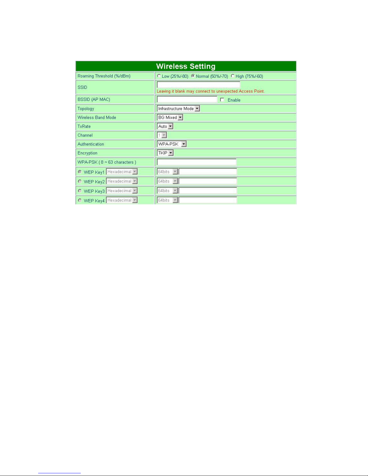
III. Attach to the access point with WPA-PSK Encryption
Topology: Infrastructure
Channel: Auto-assignment from Access point
Page 25
25
Authentication: WPA-PSK
Encryption: TKIP or AES
WPA-PSK: 8~63 Characters
Fig. 25. WPA-PSK Authorization and TKIP Encryption
5.5. COM Port Configuration
Users can configure Serial parameters including UART mode, baud rate, parity, data bit and type of flow
control and the mode of operations, which are TCP Server, TCP Client, and UDP modes. The COM Port
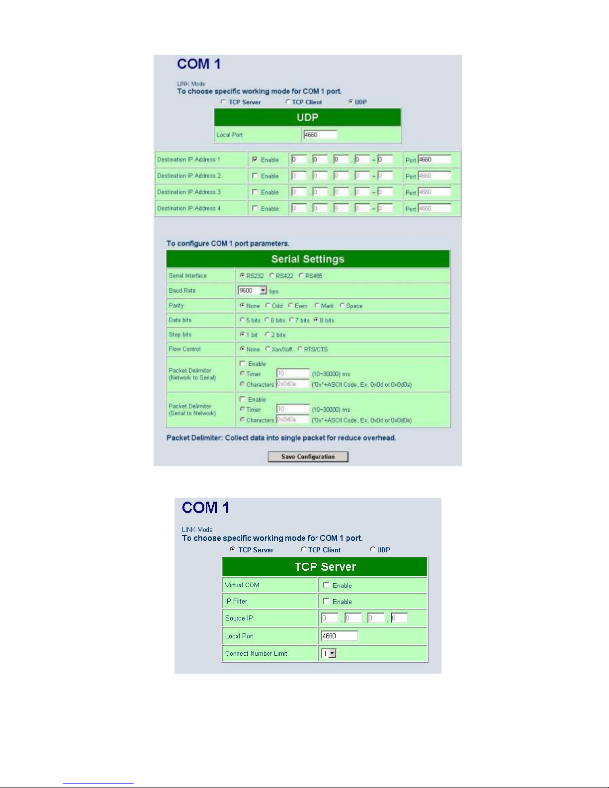
Configuration page is shown in Fig. 26.
5.5.1. TCP Server Mode
TCP Server mode is the default Link mode of Serial Settings as shown in Fig. 27. In this mode, the
connection waits for a connecting requirement from a remote host PC which is running a “Serial to IP” utility
or setting PC-W in tunneling mode. Users need to configure a listening port to allow clients establishing a
connection to this server. Default port number of COM1 is 4660.
IP filtering function is a simple ACL (Access Control List) for incoming IP packets. It can be disabled by
setting Source IP to “0.0.0.0”. Users can configure one or a group of IP address for Source IP. If IP filter is
enabled, only source IP assigned can be connected to PC-W.
Note: Enable Virtual COM mode if the remote site PC’s “Serial to IP” tool is installed
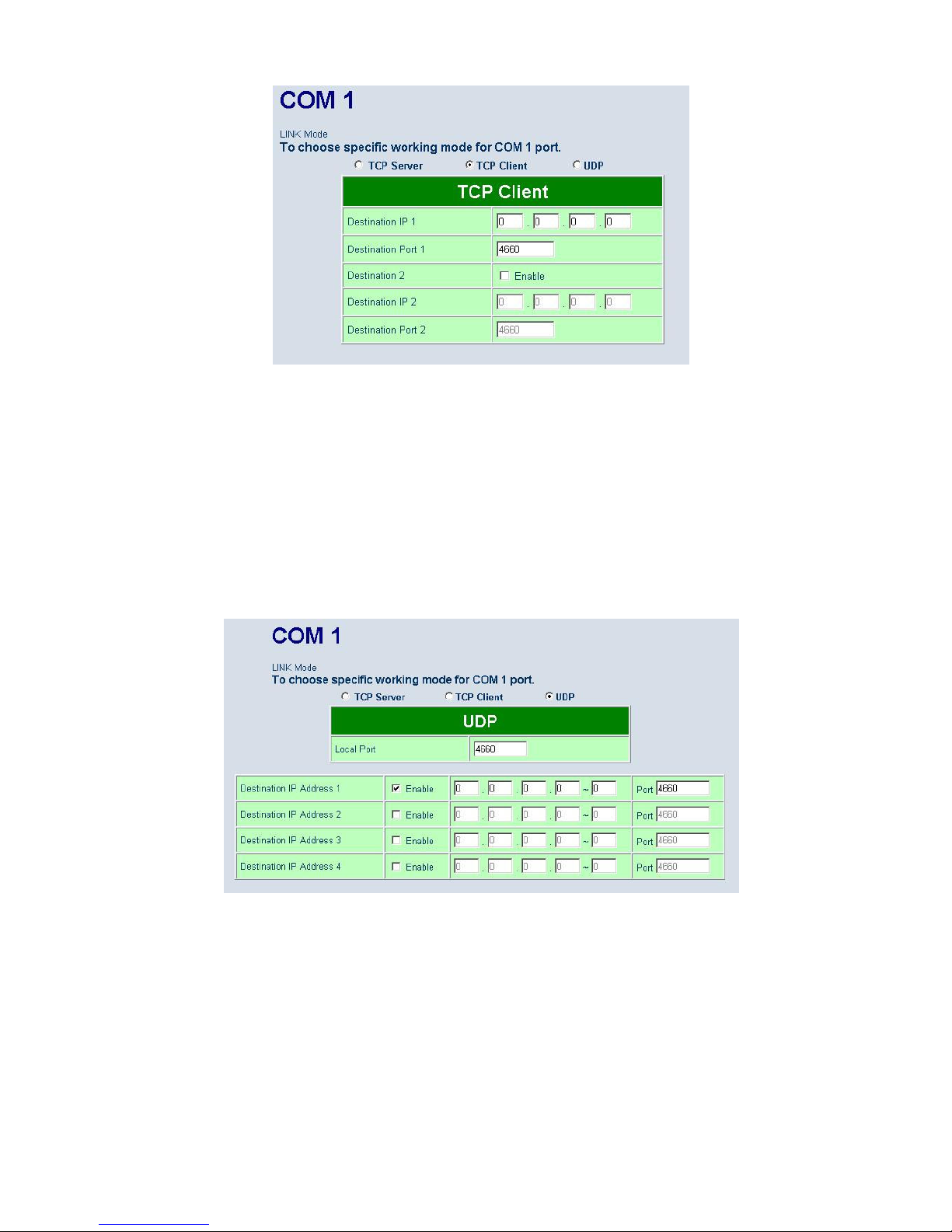
5.5.2. TCP Client Mode
Users may enter a Destination IP and Destination port (default: 4660) to establish a connection of
counter-pair (remote) host (for example, another PC-W or PC for data collection) as shown in Fig. 28. PC-W
can support up to two destination hosts simultaneously.
Page 26
26
Fig. 26. COM port Information Web Page
Fig. 27. TCP Server in Link mode
Page 27
27
Fig. 28. TCP Client in Link mode
5.5.3. UDP Mode
PC-W can be configured in a UDP mode to establish connection using Unicast or Multicast data from the
serial device to one or multiple host computers as shown in Fig. 29. Vice versa is also true. For example,
the original RS-422/ RS485 bus can be transferred and extended connection distance by PC-W.
The destination IP is assigned by a single IP or a group of IP addresses. The configuration is limited by the
Local Listening Port. For example, the PC-W listening port is 4660 which receives data sending from the
host computers. PC-W can support up to 4 group IP addresses for UDP connection, if users needed.
Note: In UDP mode, the device does not support Virtual COM mode.
Fig. 29. UDP protocol in Link mode
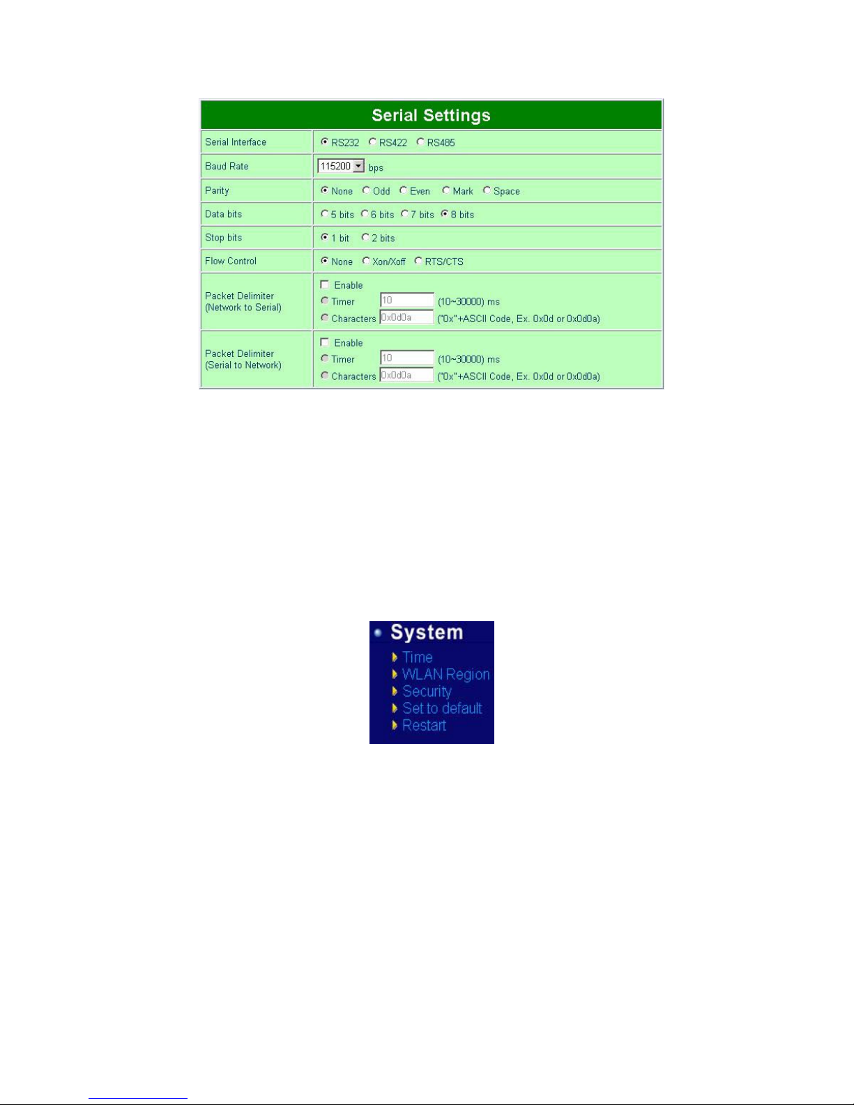
5.5.4. Serial Settings
The Serial settings of parameters for PC-W are shown in Fig. 30. Users can configure Serial parameters
including UART Mode, baud rate, parity, data bit and type of flow control.
Configure UART Mode: RS-232 or RS-485 or RS-422
Baud rate (bps): 1200, 2400, 4800, 9600, 19200, 38400, 57600, 115200, 230400
Parity: None or Odd or Even or Mark or Space
Data bits: 7 or 8
Stop bits: 1 or 2
Page 28
28
Flow control: None or Xon/Xoff or Hardware (RTS/CTS).
Fig. 30. Serial Communication Settings from Web Page
5.5.5. Packet delimiter
Packet delimiter is a way of controlling the number of packets in a serial communication. It is designed to
keep packets in track. PC-W provides two ways in parameter setting: (1) Packet delimiter by timer and (2)
packet delimiter by Character pattern. By default, packet delimiter timer is 10 ms. the range of packet
delimiter timer is 10 to 30,000 ms. For Character pattern terminator, if a character pattern is selected and a
data stream ended with “0x0a04”, then the entire data buffer of the serial device is transmitted.
5.6. Configure System
There are five items for system settings, including Time, WLAN Region, Security, Set to default and Restart.
Fig. 31. Subsystem menu of system settings by Web Interface
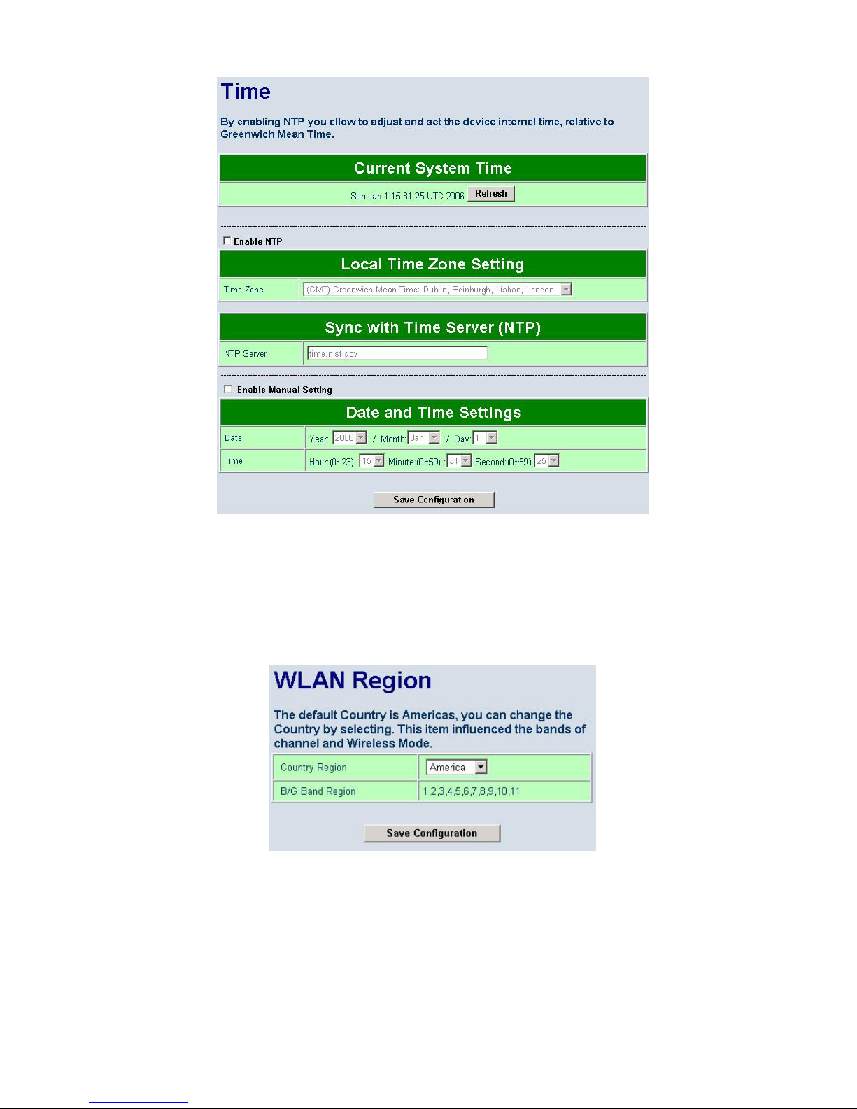
5.6.1. Configure Time by NTP Service
User can set date and time manually by enable “Manual Settings” and fill in date and time manually. User
can also enable “NTP” to obtain time automatically from a Time Zone and a NTP server.
Page 29
29
Fig. 32. Time service settings from System web page
5.6.2. WLAN Region
Click on the “WLAN Region” link and the following screen shall appear. Select the country from drop-down
list box to the country that user wants to deploy the PC-W. This selection will affect the bands of channels of
PC-W wireless mode. For example, the normal system level channel configurations for deployments are
channels 1, 6 and 11 for FCC countries and 1, 5, 9 and 13 for European Union countries.
Fig. 33. Time service settings from System web page
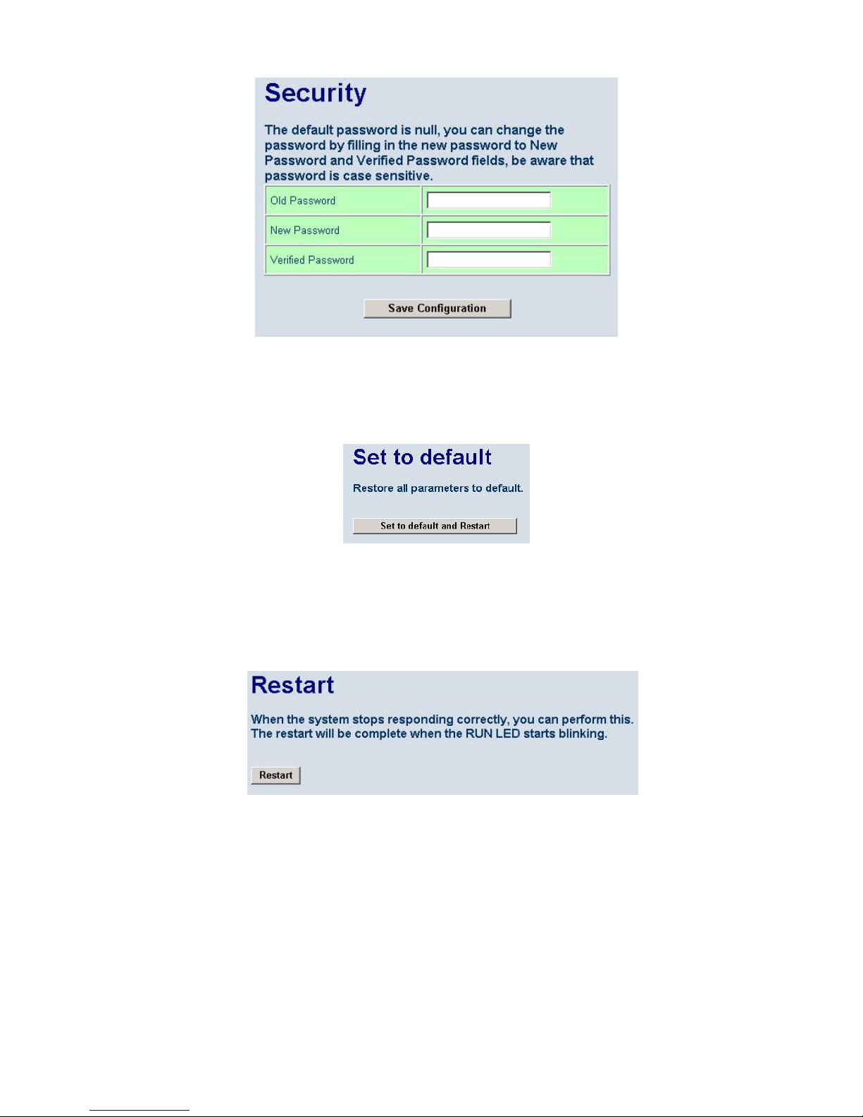
5.6.3. Security (Password Change)
Click on the “Security” link and the following screen shall appear. Enter the old password on “Old Password”
field then enter the new password on “New Password” and the “Verified Password” fields, and then click on
“Save Configuration” to update the password. The maximum number of characters of each field is 8
characters.
Note: User may press the default reset key to reset password to the default value (blank)
Page 30
30
Fig. 34. Change password from System Security Page
5.6.4. Restoring Factory Default Configurations
User can click on “Set to default and Restart” button to restore PC-W’s settings to factory default.
Fig. 35. Set all parameters to factory default by Web Interface
5.6.5. Restart System
The changes of networking parameters will take effect only after the PC-W is restarted. User can restart the
PC-W manually by click on Restart button on the restart menu web page.
Fig. 36. Restart system by Web
Page 31
31
5.7. Applications
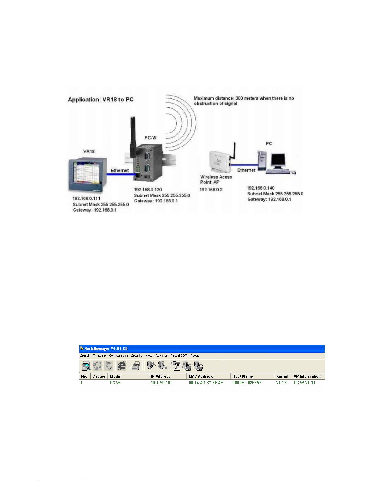
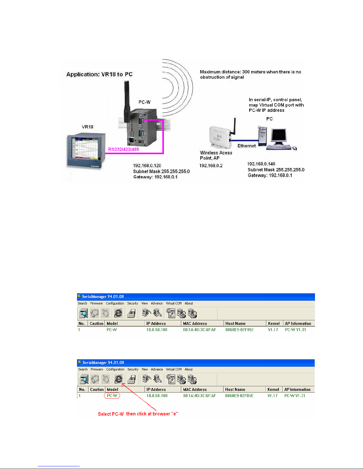
5.7.1. Paperless Recorder VR18 (Ethernet port) to Wireless Ethernet
Fig. 37. Application between PC-W and VR18
Procedure as follows..
1. Install Serial Manager in PC
2. PC-W default IP address: 10.0.50.100
3. Set IP address of PC as 10.0.50.110, Subnet Mask 255.255.255.0 & Default Gateway:
10.0.50.1. Since IP address of PC is in same domain as PC-W, now, it is possible to configure
PC-W from PC
4. Switch on Power supply to PC-W. Connect PC-W to PC via Cross over Ethernet Cable or LAN
cable
5. Open Serial Manager. If step3 and step4 is proper, then PC-W will be detected by Serial
manager and it is shown as follows
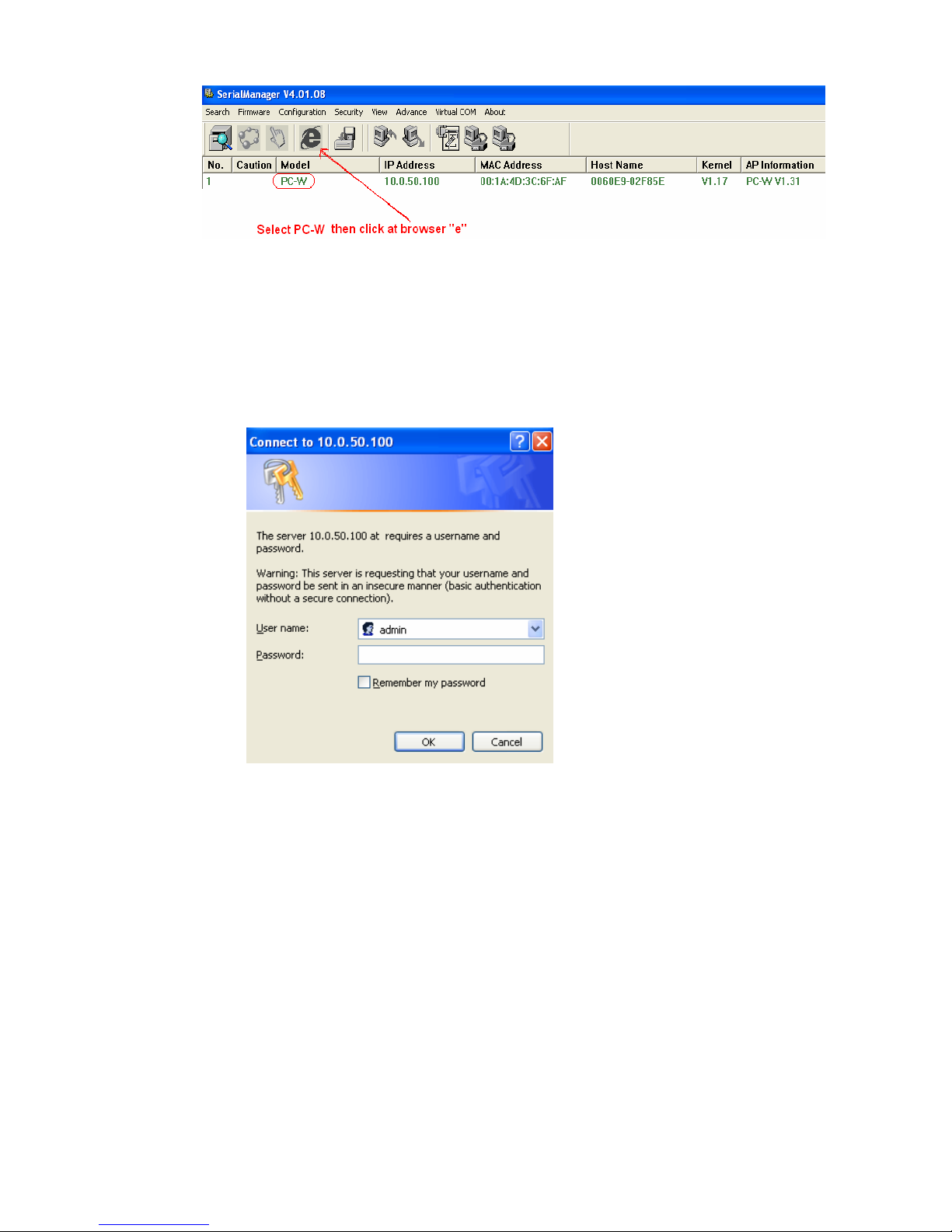
6. Now select PC-W and then click on browser “e” as follows
Page 32
32
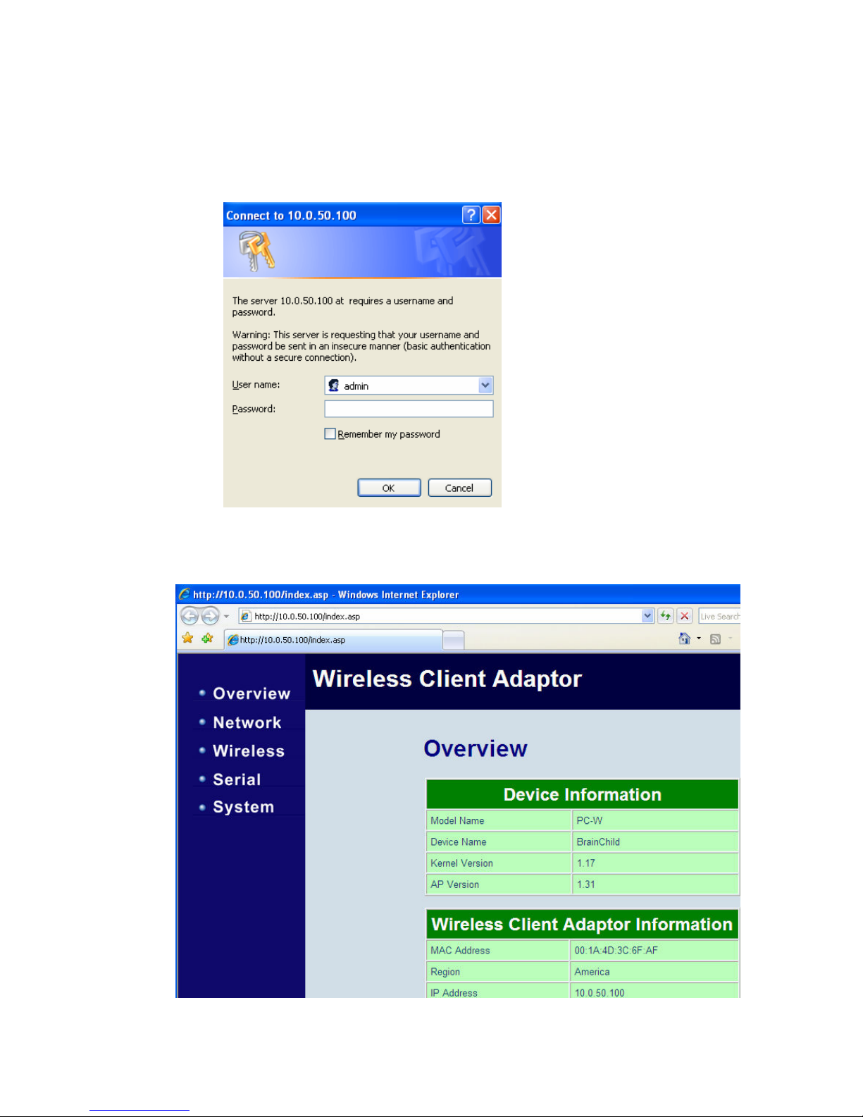
7. Log in screen appear as follows
User name = admin
Password = just leave it blank
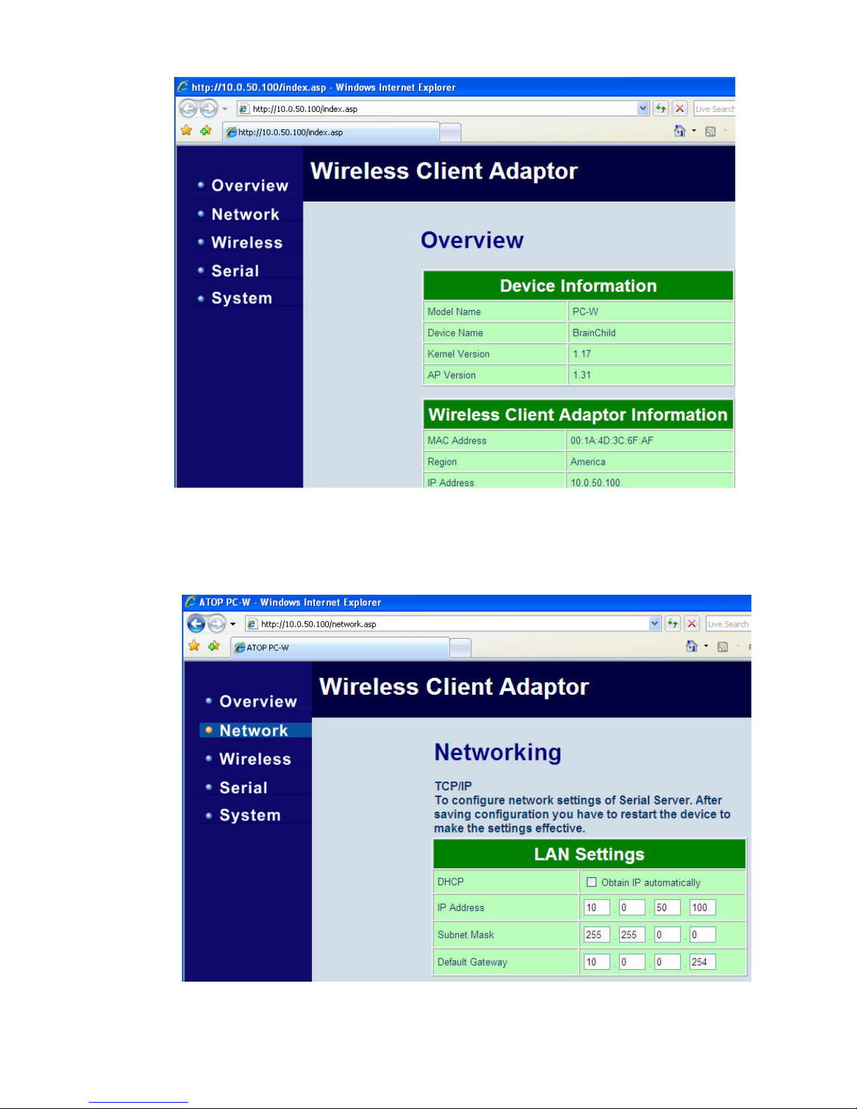
8. Click on “OK”, then Wireless Client Adopter overview screen appear as follows.
Page 33
33
9. Now, click on Network on left hand side of the Menu. It shows Networking screen as follows. It
is possible to modify IP address of PC-W at this location. We suggest not to select option at
“Obtain IP address automatically”
Page 34
34
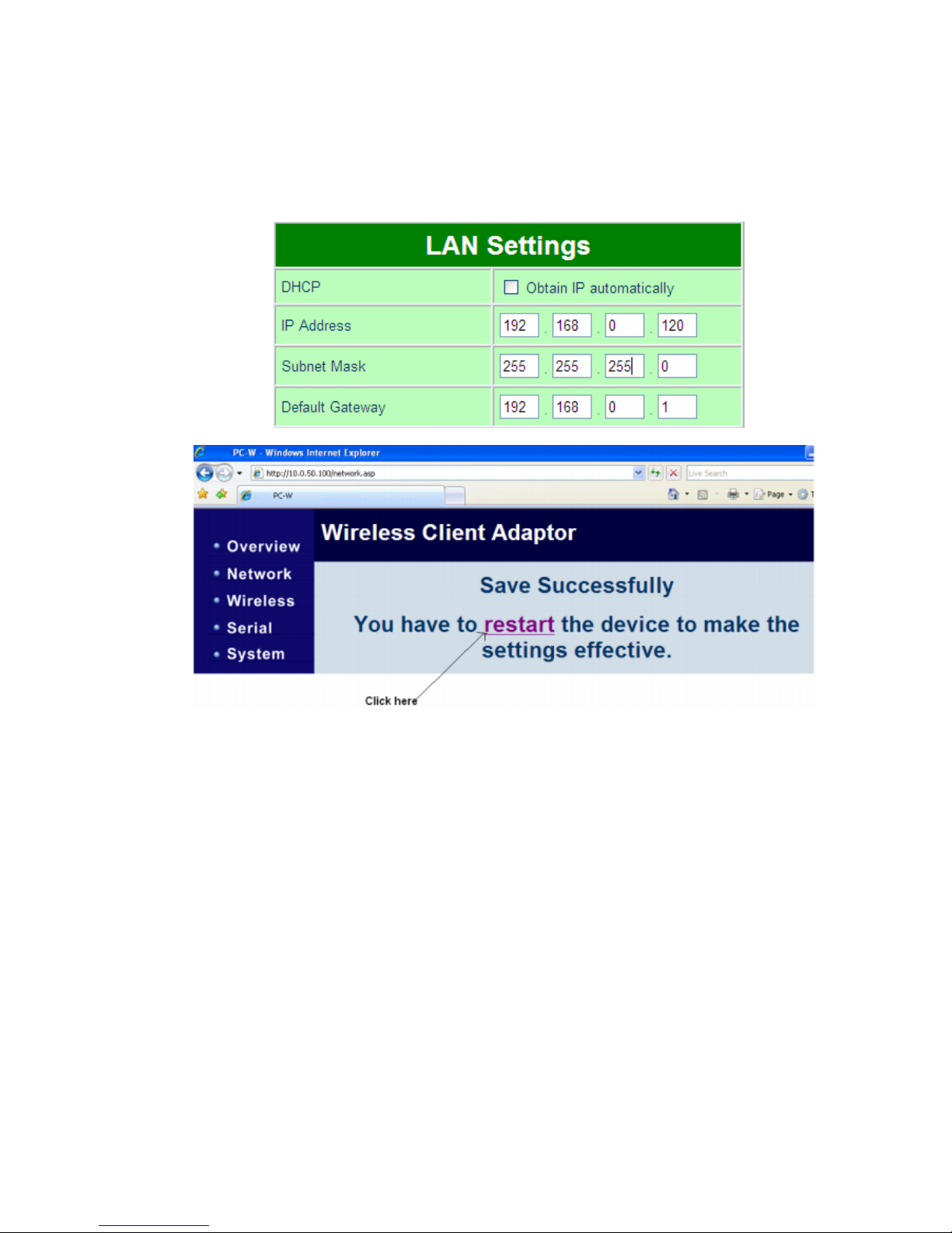
10. Paperless Recorder VR18/VR06 has Ethernet port by Default. Assume Recorder IP
address is 192.168.0.111
11. Now, it requires to Set IP address of PC-W to the above domain. So, click on Networking
and then do LAN settings properly as follows…, scroll down to bottom and then click on
“Save” button. Click on “Restart” when prompted in the screen and PC-W will restart in 60
sec
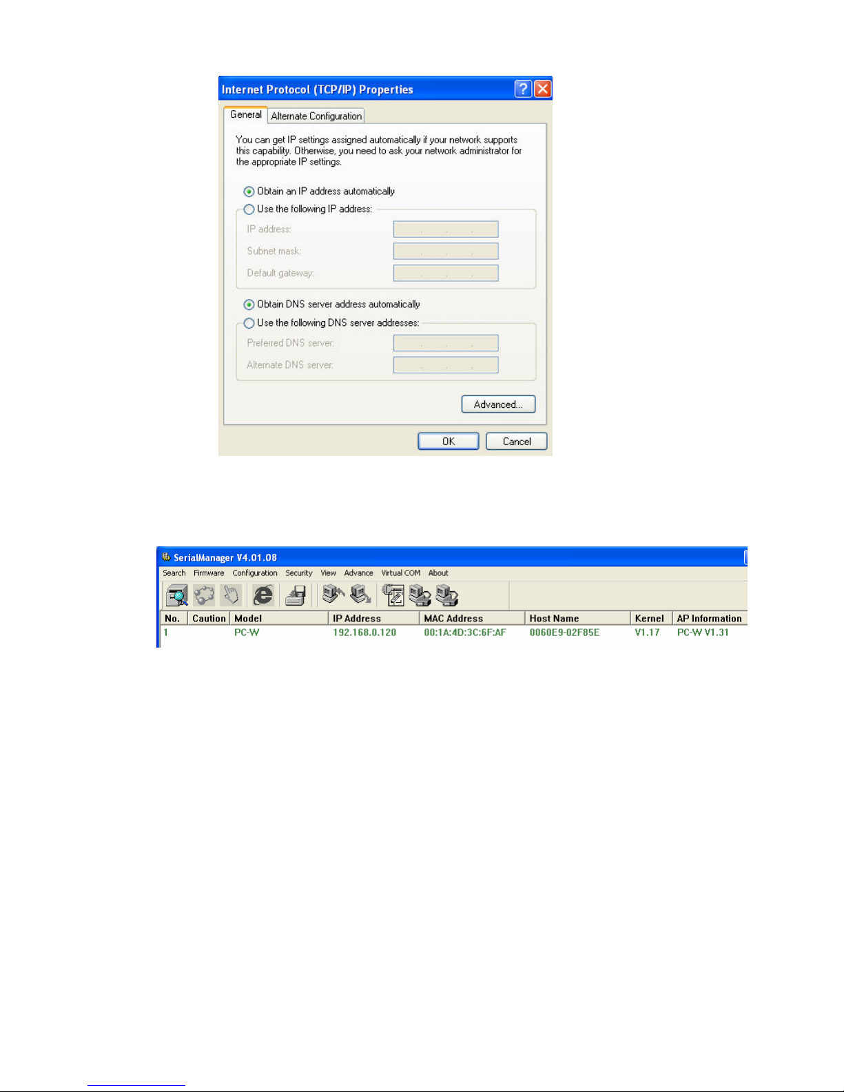
12. Now, change IP address, subnet mask and gateway address in PC in same domain of
VR18 and Wireless AP or just set “obtain an IP address automatically” as shown below
Page 35
35
13. Now, close the serial manager and open again. Then, it should detect PC-W and shows as
follows
14. If there is good communication between PC-W and Your wireless AP, then green color LED
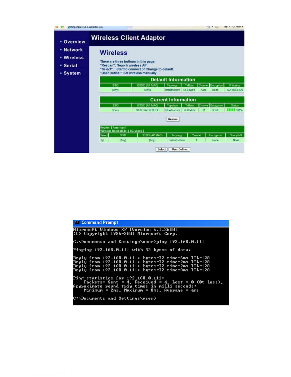
should be flashing slowly at PC-E. If not, then from the serial Manager, it requires to
connect your Wireless AP provider properly
Click on Wireless, then click on “Rescan” button, it scans all the available wireless access
points. Select the required access point and then “Save settings and Connect”. Then your
wireless access point should be selected in Current information and it also shows status
Page 36
36
15. Now, close serial Manager and disconnect Ethernet cable between PC-W and PC.
16. Now connect VR18 with PC-W via cross over Ethernet cable or Straight through cable. At
this time, VR18 is virtually connected to your wireless access point. If connection is
successful, then you can see Green color LED flashing at Ethernet port at PC-W. In
Recorder, Green LED will be on continuously and orange LED will be flashing at Ethernet
port. You may check VR18 using “Ping” instruction at dos prompt from any PC connected to
LAN or Wireless AP. If there is no reply, then it requires to check Ethernet cable, IP address
of Recorder, setting of IP address at PC-W and also wireless AP settings
17. Now, in Observer software, create a new project and enter IP address of Recorder. Please
note that there is no need to enter IP address of PC-W or Wireless AP device in Observer
software.
Page 37
37
5.7.2. Paperless Recorder VR18 (Serial port) to Wireless Ethernet
Procedure as follows..
1. Install Serial Manager in PC
2. PC-W default IP address: 10.0.50.100
3. Set IP address of PC as 10.0.50.110, Subnet Mask 255.255.255.0 & Default Gateway:
10.0.50.1. Since IP address of PC is in same domain as PC-W, now, it is possible to
configure PC-W from PC
4. Switch on Power supply to PC-W. Connect PC-W to PC via Cross over Ethernet Cable
or LAN cable
5. Open Serial Manager. If step3 and step4 is proper, then PC-W will be detected by
Serial manager and it is shown as follows
6. Now select PC-W and then click on browser “e” as follows
Page 38
38
7. Log in screen appear as follows
User name = admin
Password = just leave it blank
8. Click on “OK”, then Wireless Client Adopter overview screen appear as follows.
Page 39
39
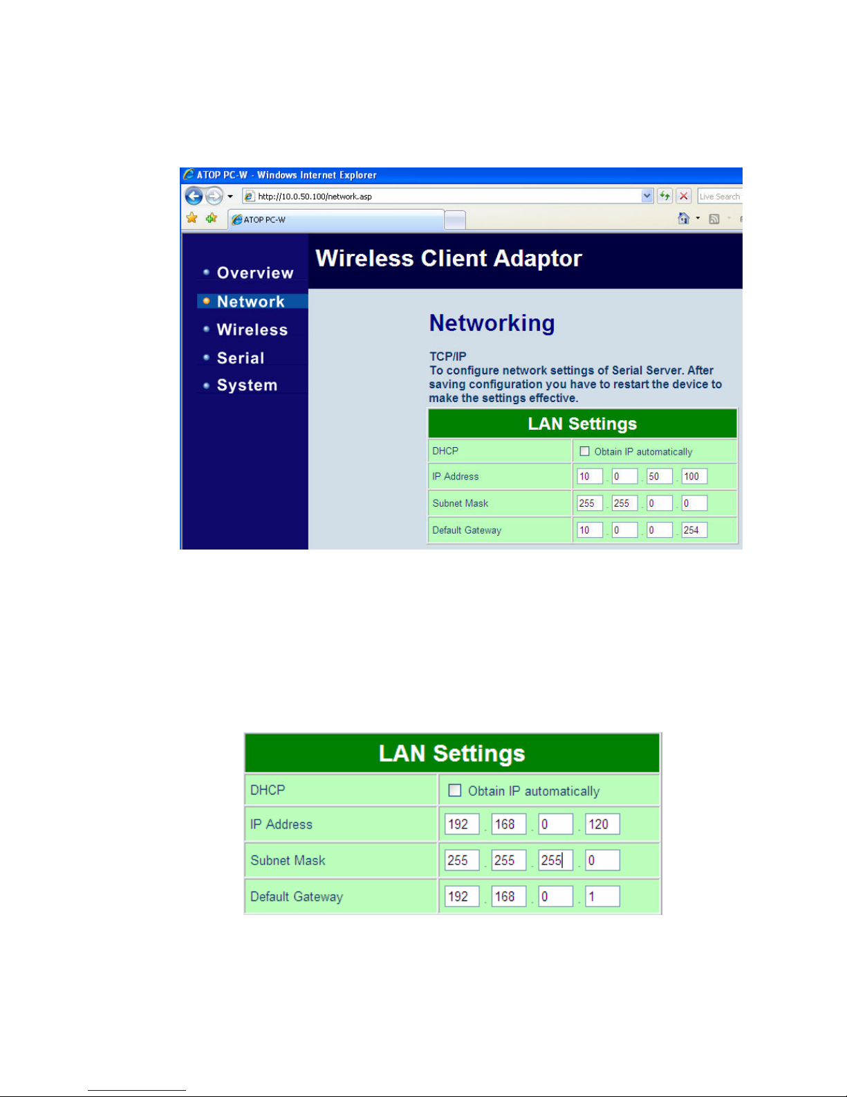
9. Now, click on Network on left hand side of the Menu. It shows Networking screen as
follows. It is possible to modify IP address of PC-W at this location. We suggest not to
select option at “Obtain IP address automatically”
10. Check IP address details of Server or wireless AP
11. Now, it requires to Set IP address of PC-W to the above domain. So, click on
Networking and then do LAN settings properly as follows…, scroll down to bottom and
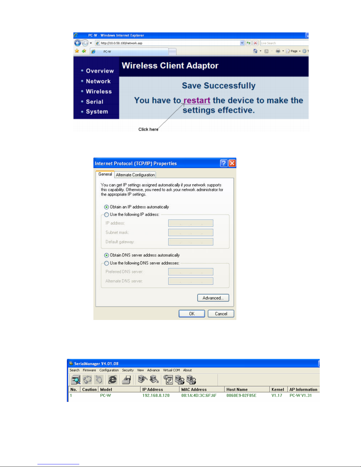
then click on “Save” button. Click on “Restart” when prompted in the screen and PC-W
will restart in 60 sec
Page 40
40
12. Now, change IP address, subnet mask and gateway address in PC in same domain of
Wireless AP or just set “obtain an IP address automatically” as shown below
13. Now, close the serial manager and open again. Then, it should detect PC-W and
shows as follows
Page 41
41
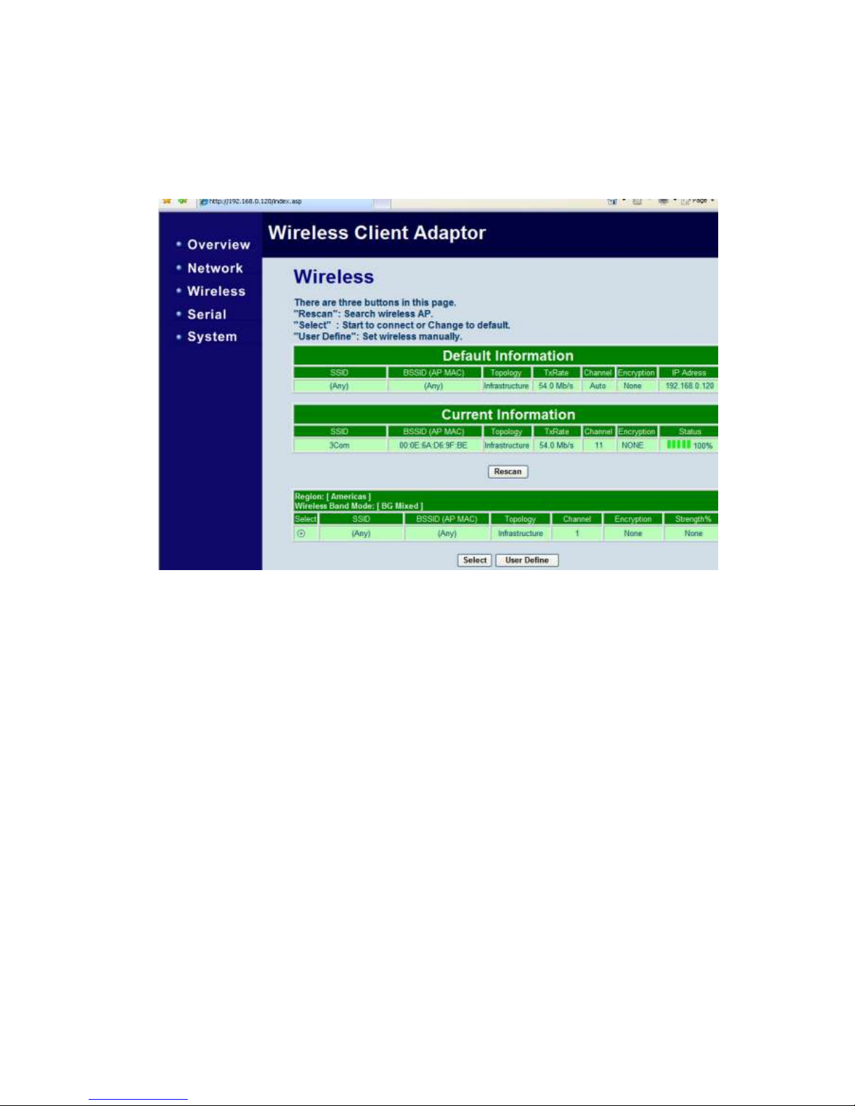
14. If there is good communication between PC-W and Your wireless AP, then green color
LED should be flashing slowly at PC-E. If not, then from the serial Manager, it requires
to connect your Wireless AP provider properly
Click on Wireless, then click on “Rescan” button, it scans all the available wireless access
points. Select the required access point and then “Save settings and Connect”. Then your
wireless access point should be selected in Current information and it also shows status
15. Now, close serial Manager and disconnect Ethernet cable between PC-W and PC.
16. Now connect VR18 with PC-W COM1 port via serial cable say RS232. At this time,
VR18 is virtually connected to your wireless access point.
17. In VR18, press “Config”, then select “Instrument” and press Enter. Set communication
parameters. Ex: PC Transfer = RS232/RS485/RS422, Address = 1, Baud rate = 38400,
data format = No, 8, 1
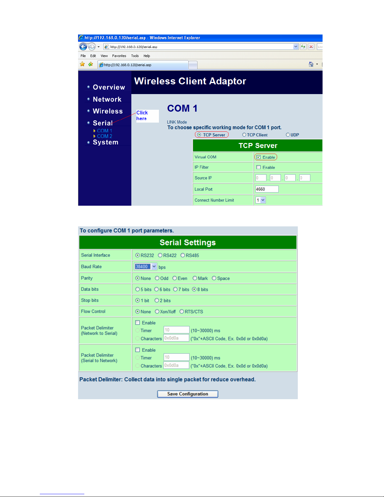
18. In serial manager, click on “Serial” and it shows the following screen. For COM1,
select option “TCP Server” and enable Virtual COM enable as shown
Page 42
42
Select PC-W COM1 settings same as VR18 COM port settings
19. Click on “Save Configuration” button. Then it appears a message “Save successfully”
20. Now, it requires to create virtual COM port in PC for PC-W device. During installation
of serial manager, Serial/IP redirector will be installed in PC. If not, install Serial/IP
software from CD
Page 43
43
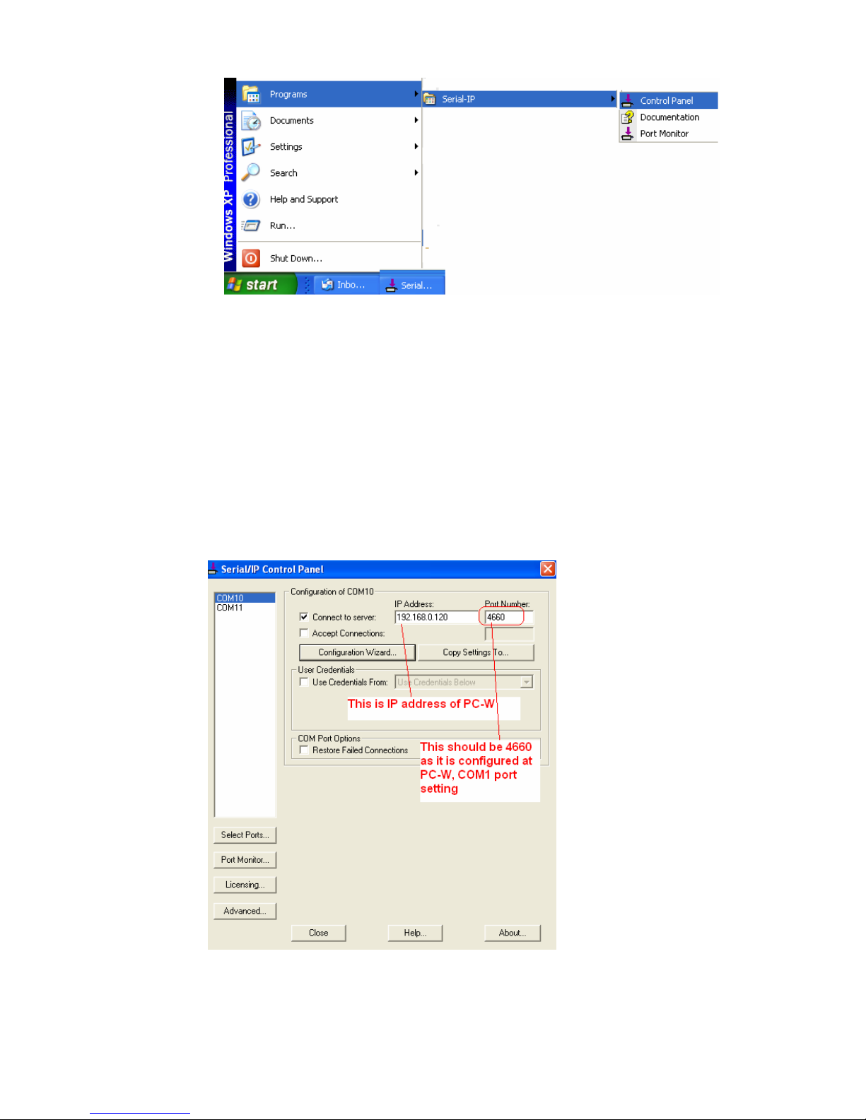
21. Open Serial-IP control panel and select the options as follows
Click at “Select ports” and then select Virtual port number required for VR18 paperless
Recorder to use in Observer software
Select “Connect to Server”
Enter IP address of PC-W
Enter port number: 4660 (This is already configured at PC-W, COM1 settings)
Now Click on “Configuration wizard” to test connection between PC and VR18 via
PC-W and Wireless Access Point
Page 44
44
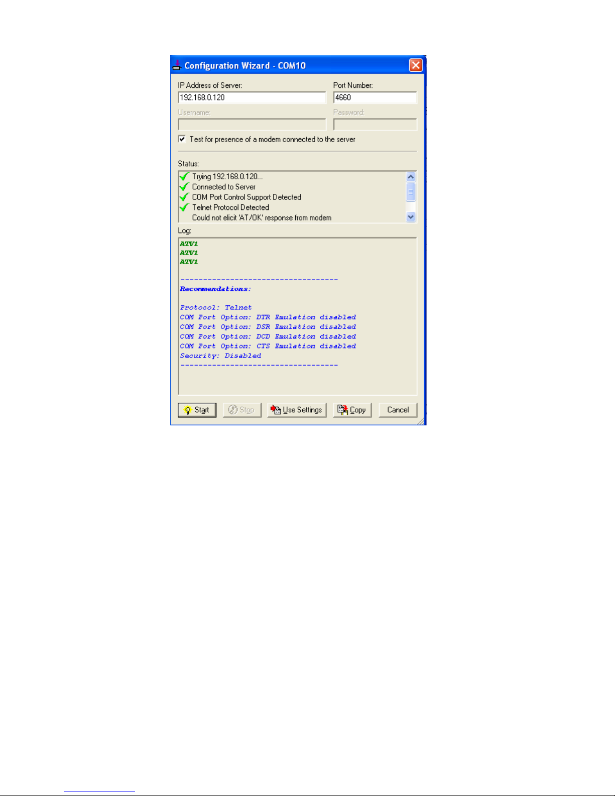
22. The above screen shows successful connection between PC and VR18 via PC-W and
Wireless access point and now COM10 is virtual COM port in PC to be used in
Observer software
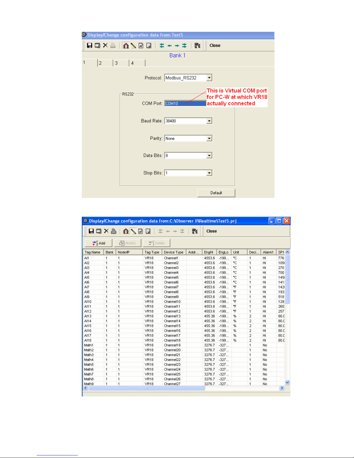
23. Now open Observer software, Real time viewer and create new project. Set bank as
shown below
Page 45
45
Page 46
46
24. Now, Real time viewer should run in PC. If there is successful communication between
PC and VR18 via PC-W and Wireless access point AP, then in PC-W, the LED status
will be as follows
COM1: T & R – Flashing
WLAN: Flashing
RUN: Flash
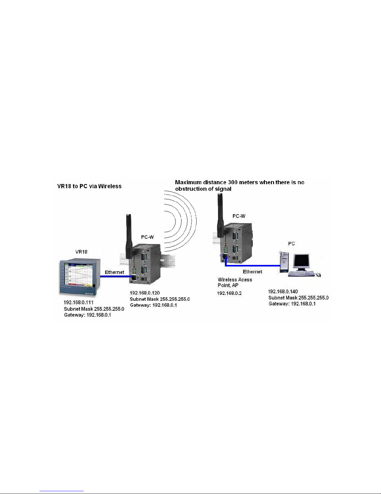
5.7.3. Paperless Recorder VR18 to PC via Wireless Ethernet (Using 2 PC-W devices)
If existing wireless AP is overloaded with many connected devices, it may affect performance of data
transfer between VR18 and PC via wireless Ethernet. In this case, it is suggested to use PC-W as wireless
AP also such that you will have dedicated Wireless Ethernet for factory applications and do not mix up with
office setup
In case of Ethernet connection between VR18 and PC-W, setup is same as procedure explained in section
5.7.1. It requires the additional setup as follows..
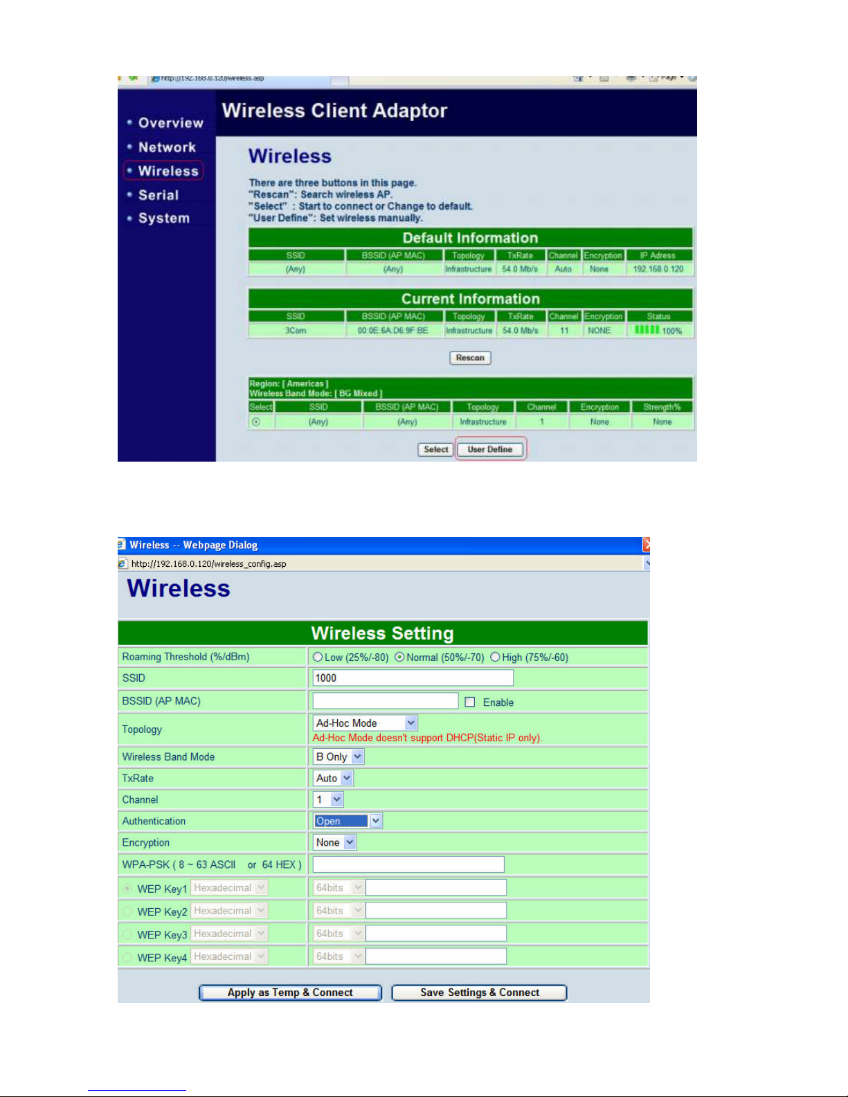
SSID should have same ID for both PC-W devices.
Click on “Wireless” and then click on “User define button” as shown attached
Page 47
47
Do settings as follows. Please note that these settings should be done at both PC-W devices and settings
should be same in both PC-W devices. Ex: SSID number, Topology, W ireless Band, Channel etc.. should
be same. Click on “Save settings and Connect” after completing settings
Page 48
48
Appendix A. Using Virtual COM
Virtual COM is a software driver for Microsoft Windows operating system to convert the data in COM port
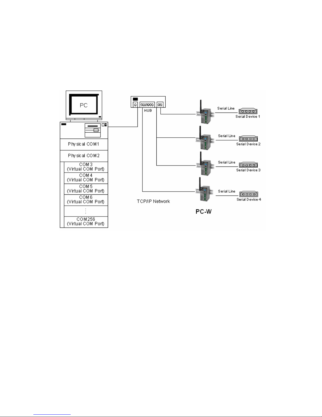
format to IP protocol format, and to transfer the data between the COM port on PC-W device and the IP
network. As shown in Fig. 38, by creating Virtual COM ports on a PC, the PC can redirect the
communications from the Virtual COM ports over a TCP/IP network to a connection port of a PC-W which is
also connected to a Serial device. By using Virtual COM ports, the application running on the PC can send
and receive data from the Serial device transparently over the TCP/IP network.
Fig. 38. Setup of a Virtual COM driver
A.1. Pre-installation Requirements
Please check the operating system on your PC complied with the following requirements:
Processor: Intel-compatible, Pentium class
Operation system: Windows Server 2003, Window Vista, Windows XP, Windows 2000, Windows
NT 4.0 SP5 or later, Windows Me, Windows 98, Windows 95, Microsoft NT/2000 Terminal Server,
Citrix Meta Frame
Windows Installer 2.0
Network: Microsoft TCP/IP networking software
A.2. Limitation and Installation
Limitation
Virtual COM driver provides users to select up to 256 COM ports as Virtual COM ports using Serial
Manager Utility software. Users can select them from a list of COM ports, which is from COM1 up to
COM256.
Page 49
49
Installation
Make sure you have turned off all anti-virus software before beginning the installation. Run VcomXXX.exe
program included in the Product CD to install Virtual COM for your operating system. At the end of the
installation, please select one or two COM ports to become the Virtual COM ports.
Uninstalling
From Windows Start menu, select Setting\ Control Panel\ Add/Remove Programs.
Select Virtual COM in the list of installed software.
Click the Add/Remove button to remove the program, or from Windows Start menu select
Programs, Virtual COM, and click Uninstall Virtual COM to remove the program.
A.3. Virtual COM Communication
Enable Virtual COM on PC-W by web interface
To access PC-W device from a web browser, typing its IP address in URL location bar, and then click on
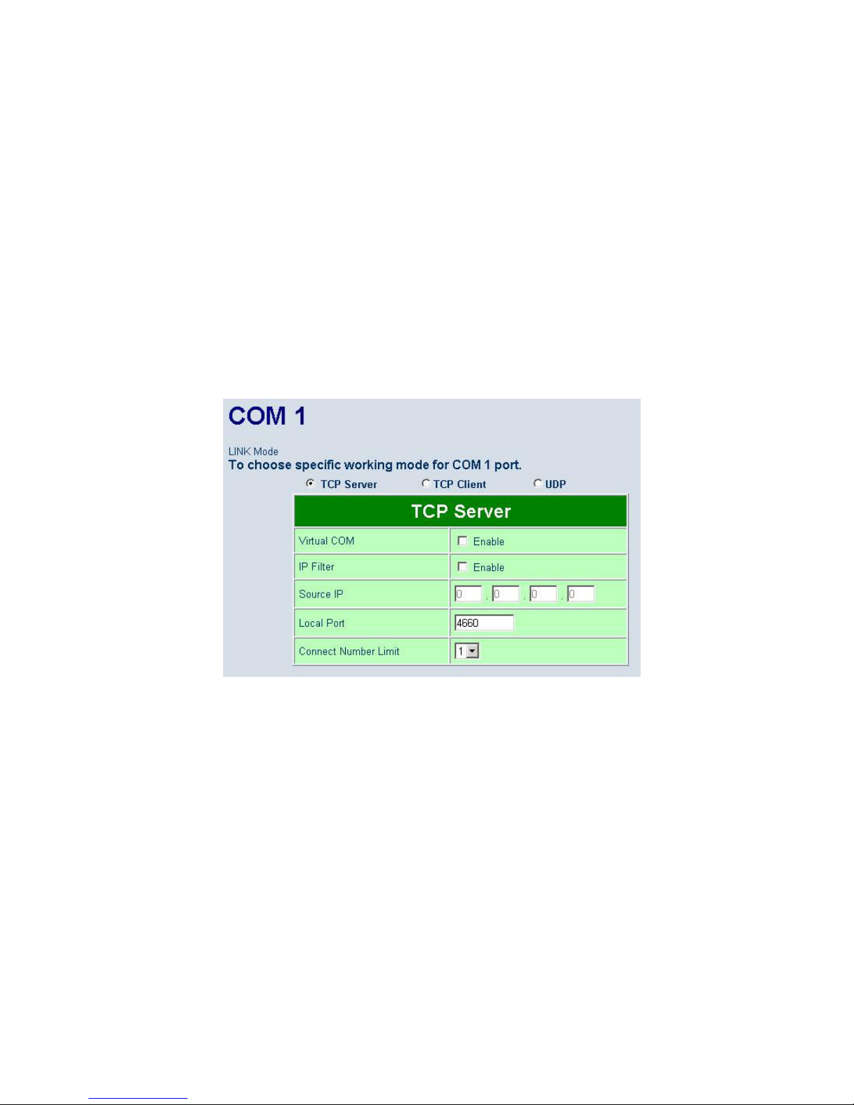
“Serial” link to access Serial page. On the top half of the page, click on “TCP Server” and enable Virtual
COM by putting a check in front of the “Enable” checkbox. Then, type in the local port number in the “Local
Port” field as indicated in Fig. 39.
Fig. 39. Enable Virtual COM Mode using Web page
Running Serial to IP for program on PC
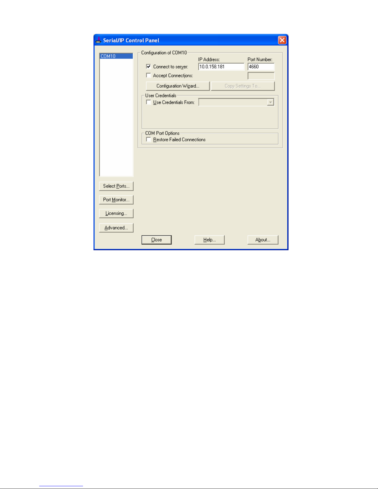
On Window Start Menu, go to Program\Serial/IP\Control panel\, The “Serial to IP for Control Panel” window
shall appear. Then select the serial port that you want to set up as shown in Fig. 40. On the right of the
panel is the sample for COM10 settings. On the left is the list of the COM ports that have been selected for
configuration. Change the list by clicking the Select Ports button. Each COM port has its own
settings. When clicking on a COM port on the left list, the Control Panel changes to reflect the parameters
of the selected port.
Note: The COM port changes become effective immediately.
Page 50
50
Fig. 40. Detailed Setting of Serial/IP Control Panel
Configure Virtual COM Ports
To configure Virtual COM port as shown in Fig. 40, it can be configured as follows.
Select a COM port on the list.
Check “Connected to Server” and enter the PC-W IP address in “IP Address” field.
In the “Port Number” field, enter the TCP port number of the PC-W. The default port is 4660.
By default, “User Credentials” is not required. However, if it does require, you will need a
username and password to access PC-W device.
Click “Configuration Wizard” to pop up a dialog to set up a configuration.
On “Username” and “Password”, the default is no login required. If the PC-W does require the
login, you must provide a username and password to access the PC-W device.
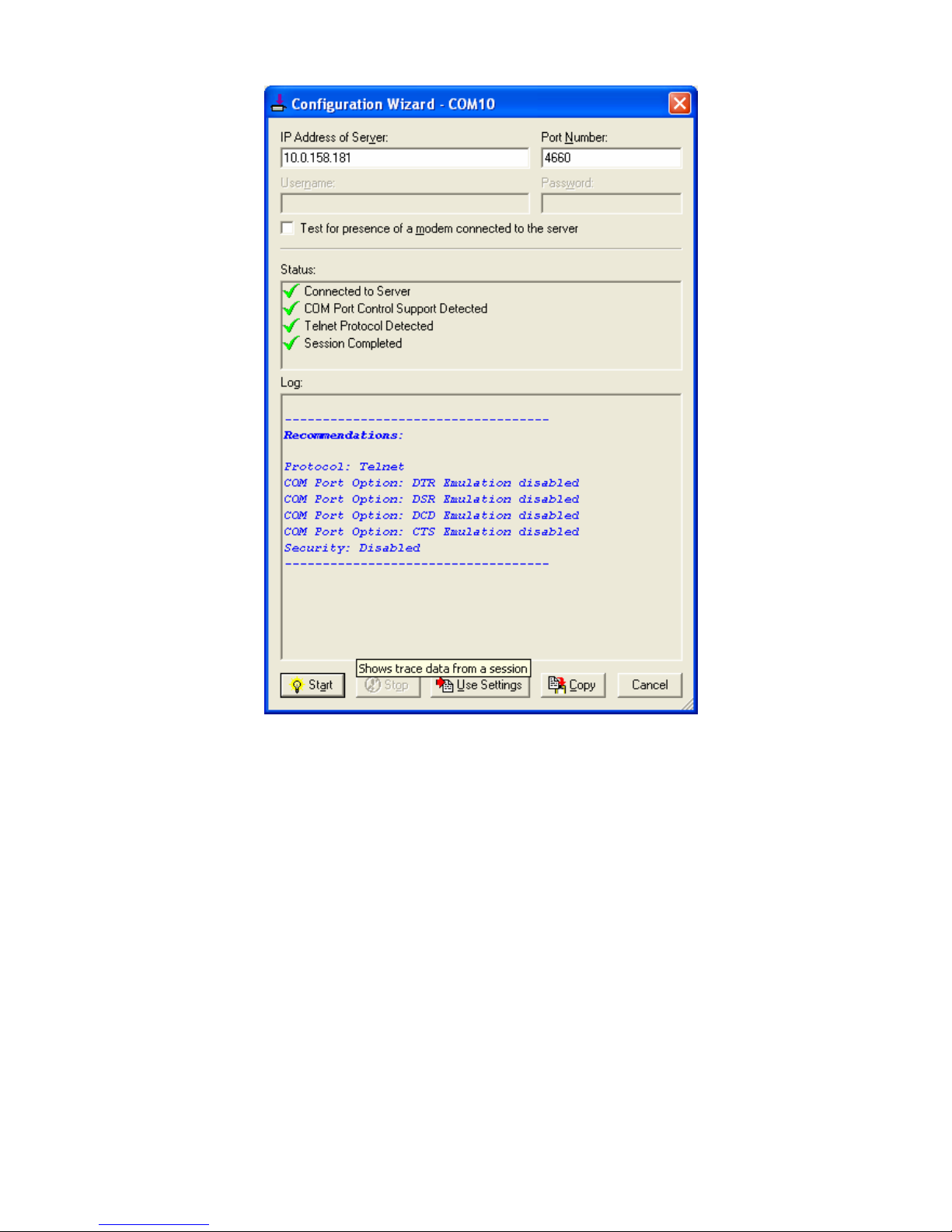
Click the “Start” button that shall appear on the wizard window. This step verifies that the Virtual
COM Redirector communicates with the PC-W. If “Log” display does not show any error, click
“Use Settings” to apply the settings and return to the Control Panel.
Settings on the “Connection Protocol” must match the TCP/IP protocol supported by the
PC-W. The Configuration Wizard is capable of determining the correct settings.
On “COM Port Options”, the settings must match the COM port behavior expected by the PC
application. The Configuration Wizard will recommend such settings.
Page 51
51
Fig. 41. Configuration Wizard from Serial to IP tool
Page 52
52
Appendix B. Configuration Utility
B.1. Serial Manager utility Introduction
Serial Manager Utility is a special tool for device management and configuration. It can realize the daily
management on PC-W devices for address search, device positioning, parameter configuring, and firmware
downloading.
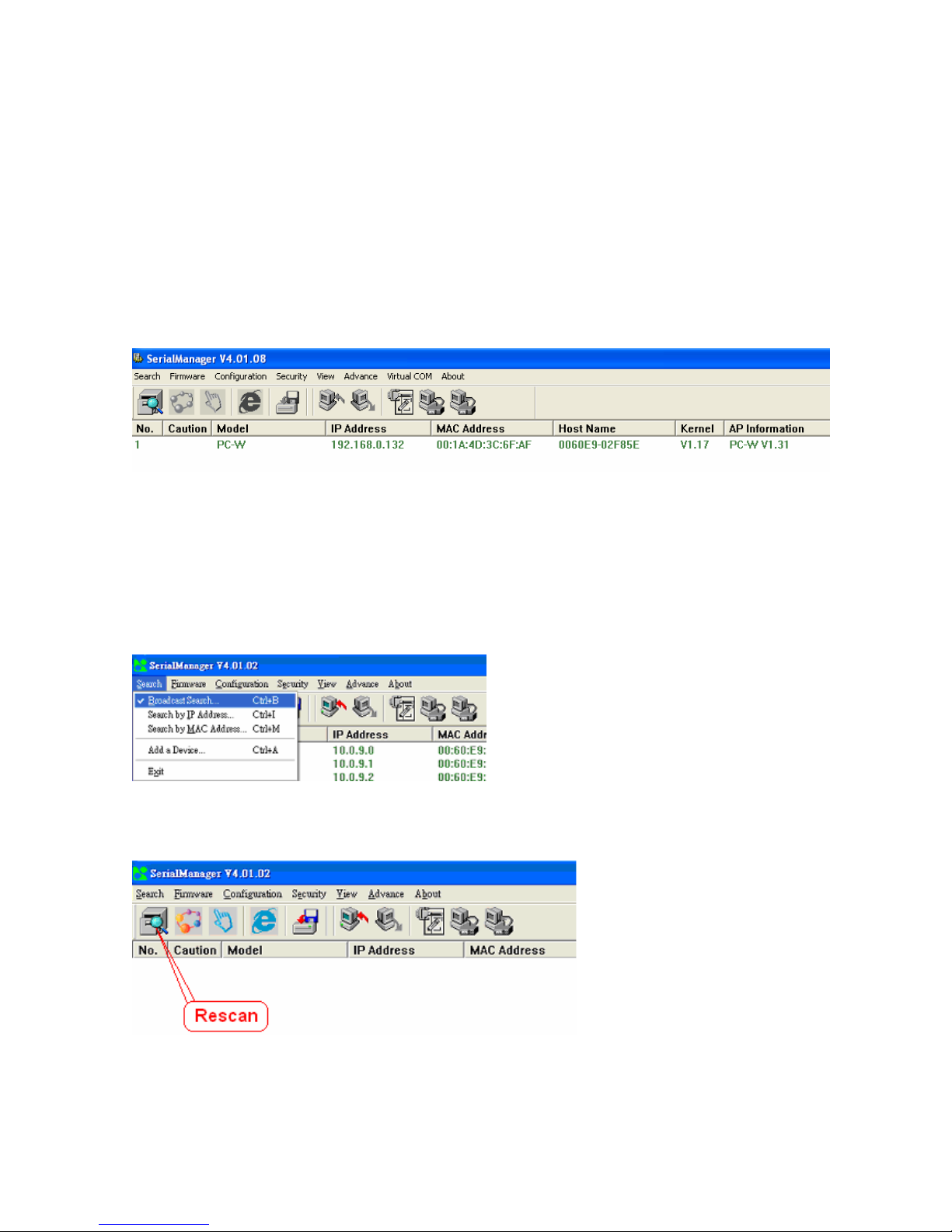
B.2. Interface
The operating interface of the Serial Manager Utility is shown below:
B.3. Functions
B.3.1. Device Search
This function is applied to search devices in the network. There are four methods to search devices, Search
by Broadcast, Search by IP addresses, Search by MAC addresses and Rescanning devices by using the
current search way. To select the search methods, users click the “Search” on the main menu which is
shown below.
Alternatively, users can select by clicking a button on the toolbar as below.
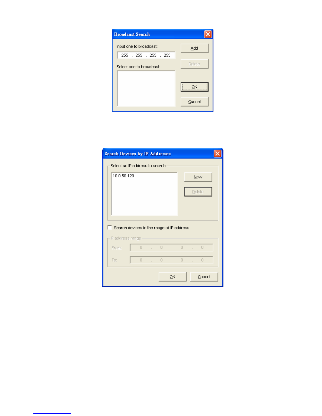
Broadcast Search
Once “Broadcast Search” is selected, a box will pop up as below. The user may type in or select different
broadcast address based on requirement.
Page 53
53
Search by IP address
Once “Search by IP Address” is selected, an interface will pop up as below. Here user may have two
options: Select an IP address to search or Search device in the range of IP address.
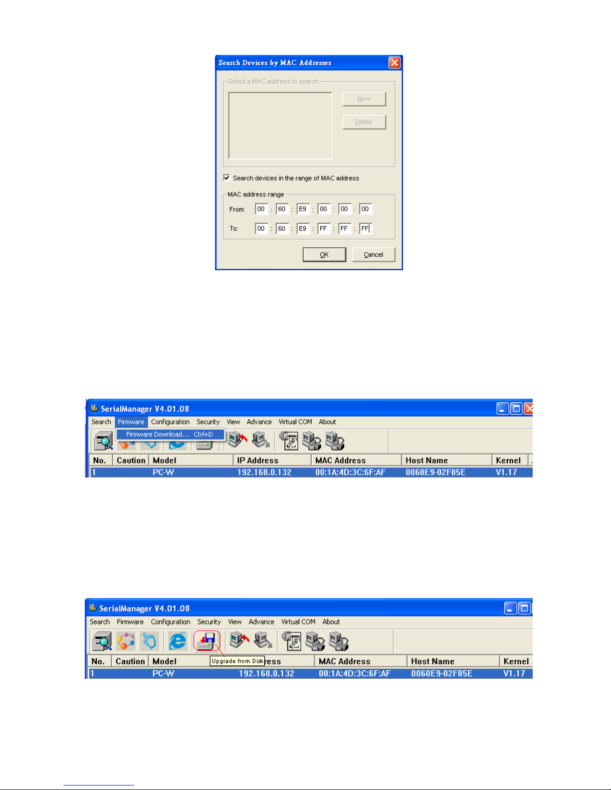
Search by MAC Address
If “Search by MAC Address” is selected, another box will pop up as below. Here the user may search in two
ways: “Search a MAC address to search” or “Search devices in the range of MAC address”
Page 54
54
Rescan
Once the user click the “Rescan” button on the toolbar, the Serial Manager utility shall re-search devices by
using the current search way.
B.3.2. Firmware
This function is applied to downloading a firmware into the selected device. The user can enter the window
for downloading by firstly clicking a designated network device, and then selecting the submenu option
“Firmware Download” in the main menu option “Firmware”, or directly clicking the button Upgrade from
disk.
And then the user can select and download the required firmware from the disk, as shown in the figure
below. The user can also select several same devices at one time, and realize the firmware updating for
them by selecting Apply for all selected devices have same model.
Operation Step:
1. Select device (Holding the [Ctrl] key for multiple selection]
2. Click the [Upgrade from disk] icon
3. Click [Upgrade] to apply for all of selected devices
Page 55

55
You may want to save device’s parameters before upgrading a firmware, and then it can be downloaded to
the device after upgrading. Alternatively, you can configure one device and save device’s parameters to
be downloaded to other devices of the same model. In some devices with JFFS2 file system supported, the
user can download the values of related parameters into the device that supports the JFFS2 file system
through a submenu Download Parameter. See details as the figure below.
A Dialog is opened and prompted for users to browse and to select a parameter file to be downloaded to
devices as shown below.
Page 56
56
B.3.3. Configuration
This function is for device configuration to set up parameters, to import and to export the parameters, and to
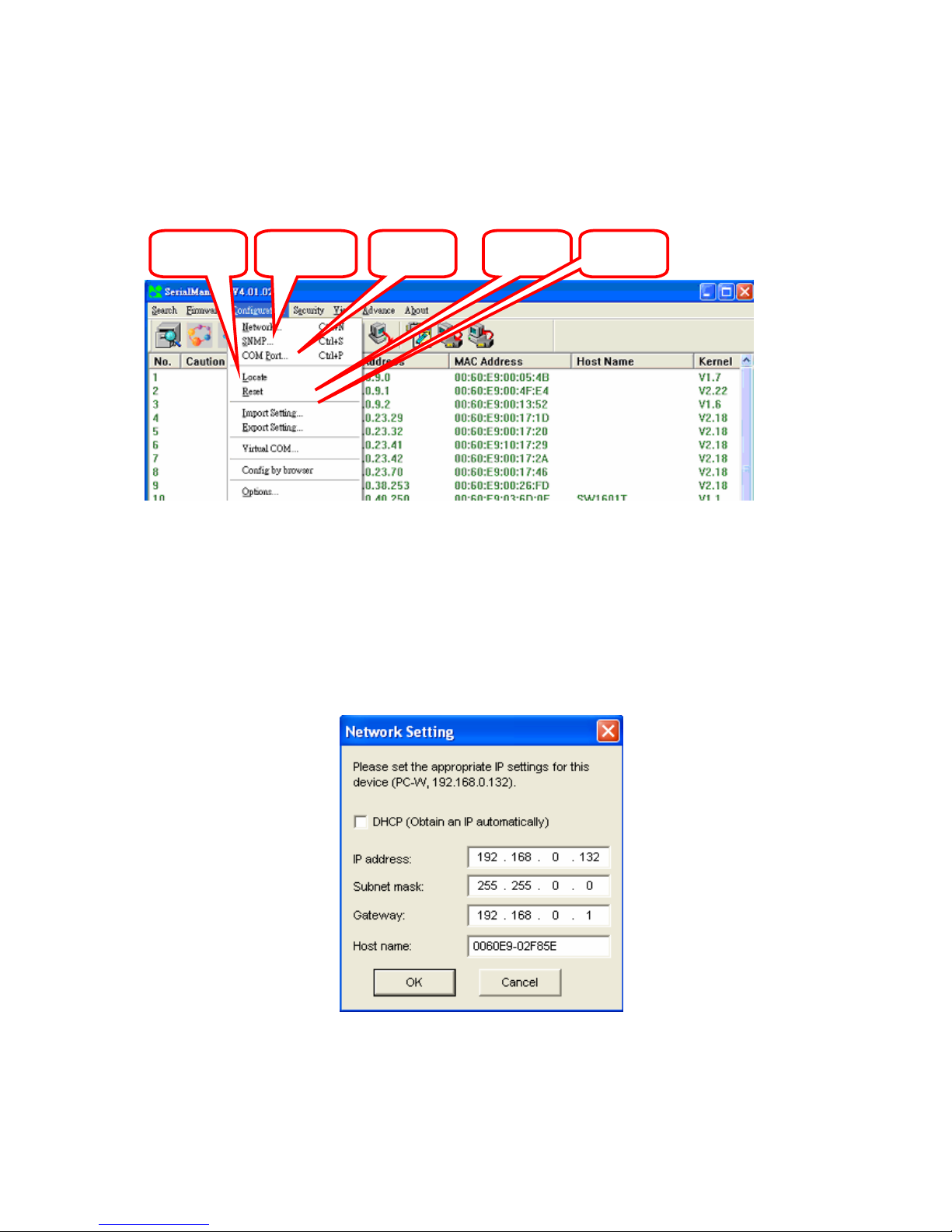
set up some options. Here is the list of configurations: “Network”, “SNMP”, “COM Port”, “Locate”, “Reset”,
“Import Setting”, “Export Setting”, “Virtual COM”, “Config by browser” and “Options.” Users can carry out a
configuration operating through menu or by clicking the corresponded button on the toolbar, shown as the
figure below:
Network
The user can modify the IP address of any selected device, shown as the figure below. You can statically
assign IP address, Subnet mask, and Gateway. Optionally, you can set up the device with a host name.
You can select DHCP option to obtain an IP address automatically.
The user can also select several devices at one time, and save the parameter information of these selected
devices into a designated parameter file by selecting "Save all the selected devices".
Network
COM
Port
Import
Setting
Export
Setting
Locate
Page 57
57
Configure by Browser
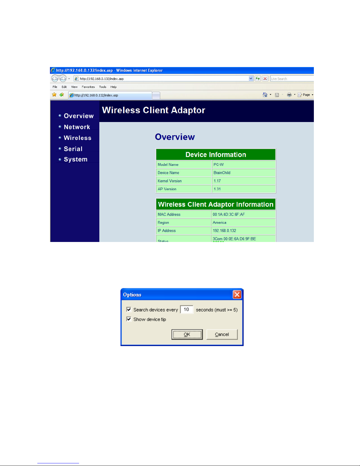
Some devices are supplied with build-in Web servers, which will be used to configure similar to Serial
Manager software. Users can carry out any parameter setting directly through the submenu option “Config
by Browser”, and a Web browser is shown in the figure below.
Option
The option is mainly applied to setting some common working rules of Serial Manager utility, such as the
device search time interval or whether to display any device information tip. The dialog is shown in the
figure below.
B.3.4. Security
This function is applied to the security protection for the network devices, so as to supply some necessary
protection to a device for configuration modifying, configuration leading-in and leading-out, and some other
important functions. Here three functions are mainly supplied, including: Login, Logout and Change
Password, shown in the figure below.
Page 58
58
Login
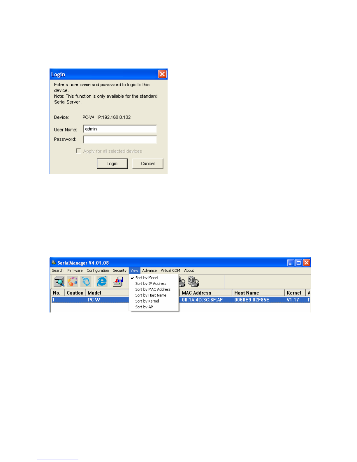
This function is applied to the login to any network device, as some important devices can only be operated
after a successful login, shown in the figure below. The user can also select several devices at one time,
and log into them at the same time by selecting “Apply for all selected devices.”
Logout
This function is applied to the logout from any network device, as the user should always carry out a logout
after he/she has finished the operating action to any important device, shown in the figure below. The user
can also select several devices at one time, and log out them at the same time by selecting “Apply for all
selected devices.”
B.3.5. View
The user can select a display mode of the network device according to his/her own requirement through the
menu option "View", such as: display in sequence of device module name, or display in sequence of IP
address and so on, shown in the figure below.
B.3.6. About
This function is mainly applied to displaying information of the Serial Manager utility
Appendix C. Upgrading System Software
For updated version of a device firmware, please contact your supplier. You may use serial Manager
software to upgrade a firmware. Please refer to Serial Manager Firmware Download sectionCritical Issues
in Upgrading Process
If the upgrading is successful, PC-W shall re-program the flash memory, and the buzzer will beep before
restarting. It takes around 5 seconds to complete the re-programming. If any error occurs during the
process, PC-W will clear the corresponding memories, and the system will remain the same as the
one before the upgrading process.
Page 59

59
Appendix D. Specifications
D.1. Hardware Specifications
System
CPU 150 MHz RISC Processor with MMU support
Memory Flash: 8 MB, 2 MB for Bootloader
SDRAM: 16 MB
Interface Mini-PCI Slot (for Wireless Module)
Watchdog Hardware Watchdog Reset
Debug Port CPU Build in COM port
Wireless LAN
Hardware Compliance to IEEE 802.11b/g Standard
Modulation Type: CCK, DQPSK, DBPSK, OFDM (11g)
Topologies Infrastructure and Ad-Hoc
Security WEP 64-bit/128-bit data encryption
WPA Compatible (TKIP/AES Encryption)
WPA2-PSK
RF Performance Tx Power: 14 dBm for 802.11b and 13 dBm for 802.11g
Rx Sensitivity: -66 dBm @ 54 Mbps, -80 dBm @ 11Mbps
Transmission Rate: 54 Mbps (max.) with auto fallback
Transmission distance: Up to 300 meters @12 Mbps, in open areas
Mobile for Fast Roaming
Interfaces Reverse SMA connector for an external antenna
Network
Hardware 10/100M Auto-Negotiation Fast Ethernet
Interface RJ-45 Connector with 2 LEDs
Protection: Built-in 1.5 KV magnetic isolation
Configuration Using Web-based or a
Serial Manager program
Serial
Protocol Support RS-232/ RS-485/ RS-422 and Software Selection
Interface D-Sub 9-pin Connector –DB Model (with 12KV ESD)
Parameters Baud Rate: 1200 bps ~ 921 kbps
Parity Check: None, Odd, Even, Mark, Space
Data Length: 7/8 Bit
Stop Bit: 1/2
Flow Control: None, Software: Xon/Xoff, Hardware: RTS/CTS
Power
Input DC 9V-48V
Consumption 4.5 W max @ Tx Mode
Mechanical
Dimensions H x W x D: 90mm x 45mm x 75mm
Page 60
60
Casing Metal Housing for IP50 Standard
Environmental
Operating
Temperature
0 to 65°C (32 to 140°F), 5 to 95% RH
Storage Temperature
-20 to 85°C (-4 to 185°F), 5 to 95%RH
Regulatory Approvals
EMC FCC/CE
Safety UL
Warranty 5 Years
D.2. Software Specifications
Software
Protocol ICMP, IP, TCP, UDP, DHCP Client, Telnet, DNS, SNMP, HTTP, SMTP,
SNTP
Utility Virtual COM Utilities for Windows 98/2000/XP/2003/Vista
Configure Utilities: Supported for Windows 98/2000/NT/XP/2003/Vista
Configuration Web browser
Windows utility software
Buffer Size TCP receiving buffer size = 8K bytes
TCP transmitting buffer size = 16K bytes
RS-232/RS-485 receiving buffer size = 4K bytes
RS-232/RS-485 transmitting buffer size = 4K bytes
D.3. Pin Assignments
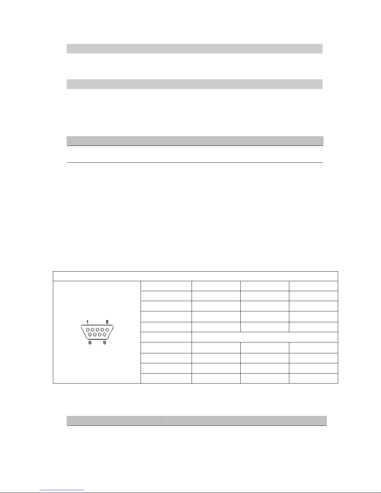
D.3.1. DB9 male connector pin assignments for Serial port
DB9
Pin# RS-232 RS-485 RS-422
1
DCD
2
RXD T+
3
TXD Data+ R+
4
DTR
5
SG (Signal Ground)
6
DSR
7
RTS Data- R-
8
CTS T-
9
RI
D.4. Beep & LED Status
D.4.1. Startup status
Message Description
^==^========^^^ (5sec)
Startup OK and application firmware is enabled
Note: Buzzer indication: “^” : Beep twice “=“ : Beep off
Page 61
61
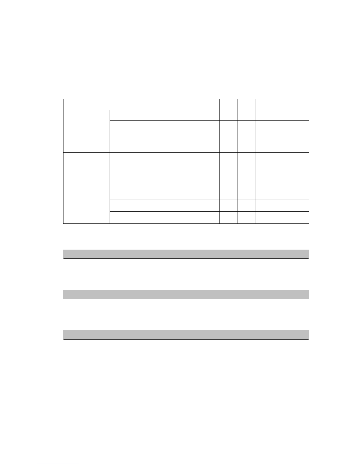
D.4.2. Wireless Signal Strength status
The Access Point link quality can be detected by LED indicator on PC-W. In a running mode, once press a
default key and then release, one of the specified actions below shall be performed depending on the
released time after you heard how many beeps. The Access Point radio link quality is indicated by the
number of LEDs lid on as shown in the table below.
Radio Link Quality LED Message
○
Off ● On ☼ Blinking
Operations
Status*
LED1 LED2 LED3 LED4 LED5
Search AP (sequentially blinking)
☼ ☼
☼ ☼ ☼ ☼
Connected AP/ Get assigned IP
☼ ☼
☼ ☼ ☼ ☼
Not matched SSID
☼
Connecting
Not available IP
☼ ☼
Signal Strength is less 20%
●
Bad Signal Strength (20%)
● ●
Poor Signal Strength (40%)
● ●
●
Fair Signal Strength (60%)
● ●
● ●
Good Signal Strength (80%)
● ●
● ● ●
Connected
Excellent Signal Strength (100%)
● ●
● ● ● ●
Note: The lowest LED is indicated for STATUS on the PC-W’s front plate.
D.4.3. WLAN LED Message
Message Description
LED Off No data is transmitting on Ethernet
LED Blinking Data is transmitting on Ethernet
D.4.4. COM Port LED Message
Message Description
LED off No data is transmitting on COM port
LED Blinking Data is transmitting on COM port
D.4.5. RUN LED Message
Message Description
LED Blinking (0.5 sec interval)
AP firmware is running
 Loading...