

Page 1
User Manual
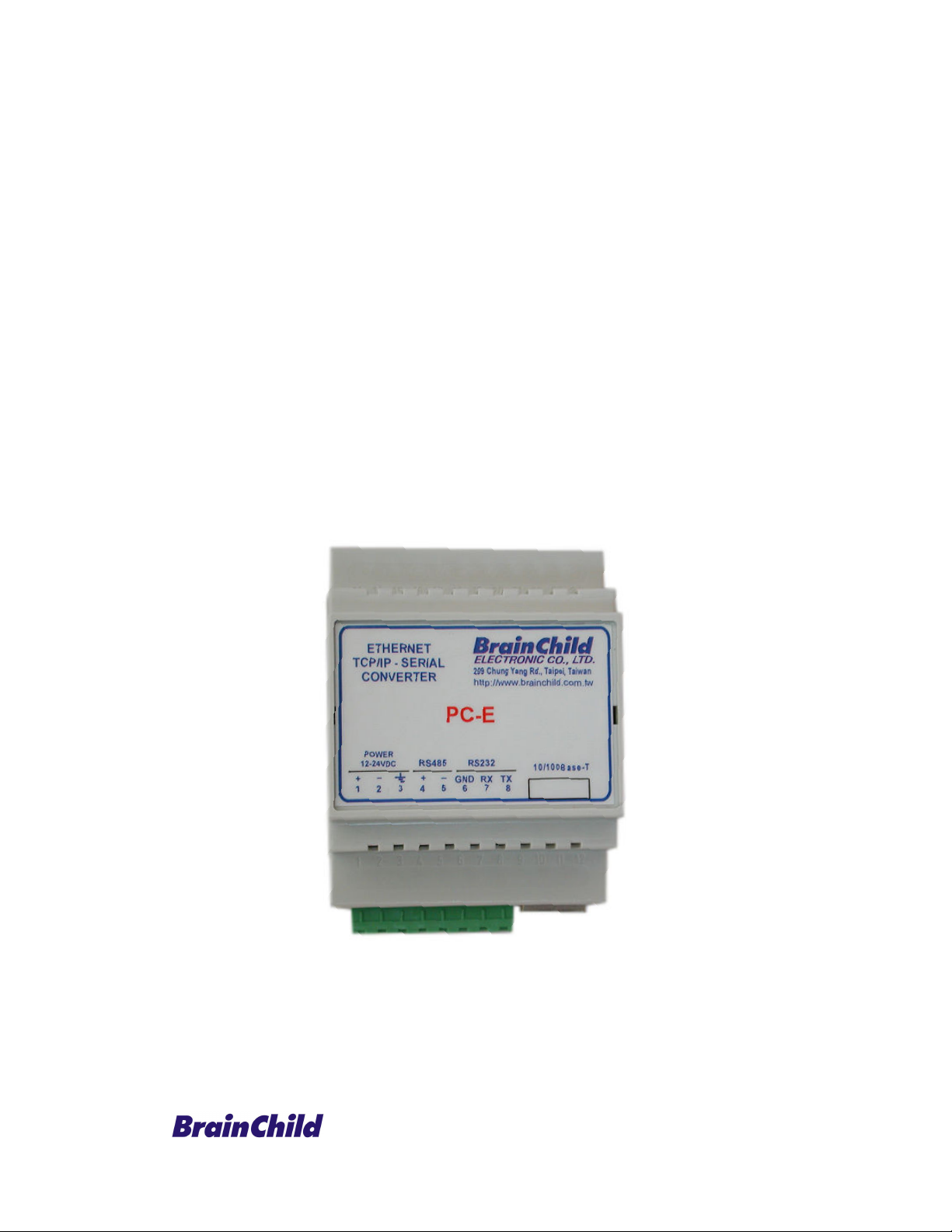
Protocol Converter
PC-E, Serial to Ethernet
(RS232/485 Modbus RTU to Modbus TCP/IP)
UMPCEC
Rev 3.0, 6/2012
Page 2

COPYRIGHT NOTICE
This manual is a publication of Brainchild Electronics Co. Ltd. and is provided for use by its
customers only. The contents of the manual are copyrighted by Brainchild Electronics;
reproduction in whole or in part, for use other than in support of Brainchild Electronics
equipment, is prohibited without the specific written permission from Brainchild Electronics
SERVICE
If service is required then pack the unit in its original packaging container or, if unavailable, any
suitable rigid container. If a substitute container is used, surround the unit with shock absorbing
material; damage in shipment is not covered by the warranty. Include a letter with the unit
describing the difficulty of usage and request Brainchild for RMA procedure.
Send the equipment to the following address:
Brainchild Electronic. Co. Ltd
No. 209, Chung yang Road, Nan Kang Dist, Taipei, Taiwan
Tel: +886-2-27861299
Fax: +886-2-27861395
Email: [email protected]
All returns will be tested to verify customer claims of noncompliance with the product warranty.
Improper return packaging, which makes verification impossible, will void the warranty. If
noncompliance is verified and is not due to customer abuse or the other exceptions described
with product warranty, Brainchild Electronics will, at its option, repair or replace the Product
returned to it, freight prepaid, which fail to comply with the foregoing warranty, provided
Brainchild is notified of such noncompliance within the one-year warranty period.
ASSISTANCE
This manual is designed to provide the necessary information for trouble-free installation and
operation of your new Serial to Ethernet Protocol converter. However, if you need assistance,
please call Brainchild Electronic Co. Ltd. at +886-2-27861299 Ext 613
Or visit our web site at www. Brainchild.com.tw
Warranty Certificate
For New product: This product is warranted against defects in materials and workmanship for a
period of 12 months from the date of shipment to Buyer. For Rectified Products: Any product
that will be replaced will have Warranty for 6 months or up to Original Product Warranty
period whichever is greater. The warranty is limited to repair or replacement of the defective
unit at the option of the manufacturer. This warranty is void if the product has been altered,
misused, dismantled, or otherwise abused.
ALL OTHER WARRANTIES, EXPRESSED OR IMPLIED, ARE EXCLUDED, INCLUDING
BUT NOT LIMITED TO THE IMPLIED WARRANTIES OF MERCHANTABILITY AND
FITNESS FOR A PARTICULAR PURPOSE.
MAINTENANCE & SERVICE
2
Page 3

There are no parts that can be serviced by the user. Service should be performed on a unit
substitution basis only. Do not attempt to remove, replace or service any printed circuit board,
components or any hardware/software related with display product. If problem within the
display product occurs, contact the factory for service information or repair.
Any Mechanical or Electrical Modification to this Unit will void
All Warranties
DISCLAIMER
Information contained herein is subject to change without notice. Every precaution has been
taken in the preparation of this manual. Nevertheless, Brainchild Electronics assumes no
responsibility, express or implied, for errors or omissions or any damages resulting from the use
of the information contained in this publication.
All trademarks belong to their respective owners
3
Page 4

TABLE OF CONTENTS
1. Description........................................................................................................................................5
2. Operating Modes...............................................................................................................................5
2.1 Mode 0 ......................................................................................................................................5
2.1.1 Modbus gateway – Using TCP..........................................................................................5
2.1.2 Transparent Mode – Using TCP........................................................................................6
2.1.3 Modbus gateway – Using UDP .........................................................................................6
2.1.4 Transparent Mode – Using UDP.......................................................................................6
2.2 Mode 1 ......................................................................................................................................7
2.2.1 Modbus gateway – Using TCP..........................................................................................7
2.2.2 Transparent Mode – Using TCP........................................................................................7
2.3 Mode 2 ......................................................................................................................................7
3. Physical Dimensions .........................................................................................................................8
3.1 Grounding/Shielding .................................................................................................................8
4. Technical Specification.....................................................................................................................9
5. Wiring ...............................................................................................................................................9
6. Configuration ..................................................................................................................................10
6.1 Power Connections .................................................................................................................10
6.2 Ethernet Connection................................................................................................................10
6.3 Indication LED'S.....................................................................................................................10
6.4 Connecting to a PC which is not Connected to a Network .....................................................11
6.5 Connecting to a PC which is connected to a Network ............................................................12
6.6 Testing the Connection ...........................................................................................................13
6.7 Viewing Web Pages ................................................................................................................14
6.8 Troubleshooting Guide ...........................................................................................................15
6.9 Parameter Configuration .........................................................................................................16
6.10 RS485 termination ..................................................................................................................19
6.11 Setting the Jumpers for the RS485 Termination (J5) ..............................................................19
7. Conformity Certificate ....................................................................................................................21
8. Examples.........................................................................................................................................22
8.1 Controller to DAQ software via PC-E ....................................................................................22
8.2 IO modules to DAQ software via PC-E ..................................................................................28
4
Page 5

1. Description
The Ethernet/Serial Converter enables serial devices, such as Modbus based IO modules
communicating on RS232/485 to be connected to a 10/100 Base-TX Ethernet network. The
Ethernet/Serial Converter can be configured to operate in a number of different modes
depending on the application. It can be configured as a transparent data link or it can perform
the gateway function of converting Modbus TCP messages to Modbus RTU messages.
The PC-E converters are factory programmed with a default IP address of 192.168.0.112.
This address must be changed before the converter is added to an existing Ethernet network.
The IP address in the converter should be unique in the network and can be changed via the
Web Server. Web server allows setting IP address, serial data format and operating modes.
The web server can be accessed by most web browsers like Internet explorer, Netscape etc.
PC-E supports FTP protocol which enables the web pages to be customized if required.
The web page address for viewing the setup parameters is
web page address for configuring the converter is
The master device which is polling the modules must be configured with the IP address of the
converter and with the Modbus ID of the Modbus modules. As each RS485 network is
separate, it is possible to have repeated Modbus ID's on the RS485 networks. The IP address
differentiates between the different RS485 networks. Consequently, many hundreds of IO
modules may be added to an Ethernet network.
http://192.168.0.112/ip.htm
http://192.168.0.112/index.htm the
2. Operating Modes
2.1 Mode 0
Mode 0 is the standard server configuration for most Ethernet/serial converter applications.
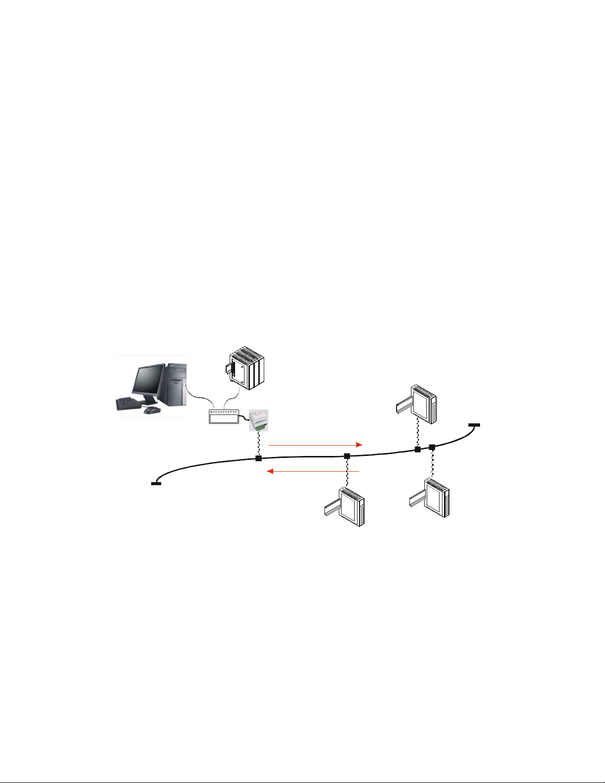
This mode has been designed to service multiple sockets which enables up to 4 masters to
communicate with the slaves connected to the converter.
Each socket is serviced in turn, and any message in the socket is sent out on the serial port.
The converter then starts a timer waiting for a reply. When a reply is received the messages
is put into the initiating socket and send out on the Ethernet network. The converter then
checks the next socket. If no reply is received then the timer expires and the converter checks
the next socket. This timer is configured on the ip.htm web page and is labeled” Serial Reply
Timeout”.
The converter can also accept messages on UDP instead of TCP. Operation is the same and
does not need any special configuration.
There are a number of different configurations for this mode as follows:
2.1.1 Modbus gateway – Using TCP
When used as a Modbus gateway the client must be configured to use Port 502. This is a
reserved port number for Modbus TCP applications and informs the converter that it must
implement the protocol conversion from Modbus TCP on the Ethernet network to Modbus
RTU on the serial network.
5
Page 6
PLC
Digital
Outputs
8DI
Inputs
8TC
Digital
Request
2.1.2 Transparent Mode – Using TCP
When used in transparent mode the client must be configured to use Port 1234. This port
number informs the converter that any data that is received in a socket must be transmitted
out the serial port without any protocol conversion.
2.1.3 Modbus gateway – Using UDP
When used as a Modbus gateway the client must be configured to use Port 502. This is a
reserved port number for Modbus TCP applications and informs the converter that it must
implement the protocol conversion from Modbus TCP on the Ethernet network to Modbus
RTU on the serial network.
2.1.4 Transparent Mode – Using UDP
When used in transparent mode the client must be configured to use Port 1234. This port
number informs the converter that any data that is received in a UDP datagram must be
transmitted out the serial port without any protocol conversion.
PC
Modbus
Master
UTP
Inputs
Modbus
Slaves
8DO
Modbus
Master
120 Ohm Termination
Ethernet
Hub/Switch
RS485 Network
Ethernet
RS232/RS485
Converter
Response
TC
Fig: Max. 4 masters can access data of the IO modules via PC-E in Mode 0
Note: Max. 127 IO modules can be connected on each RS485 network
Note: Max. 254 temperature controllers can be connected on each RS485 network
Note: Combination of IO modules and Controllers: Maximum 254 on each RS485 network (IO
modules from address 1 to 127 only)
Note: If DAQ software is used, it supports maximum 4 banks. Each bank can be connected
with either RS485 or Modbus TCP. DAQ software support max. 2048 tags.
6
Page 7

2.2 Mode 1
Mode 1 is a server configuration and is similar to Mode 0 except that this mode only makes
use of a single socket. By default, Mode 1 for simple applications.
Ex: Access IO modules data in one PC via PC-E on Ethernet.
This single socket implementation waits for messages to come in on the Ethernet network
and sends them out the serial port. Any messages being received on the serial port are sent
out on the Ethernet network. As there is only one socket, there is no need for the timer as in
mode 0.
There are a number of different configurations for this mode as follows:
2.2.1 Modbus gateway – Using TCP
When used as a Modbus gateway the client must be configured to use Port 502. This is a
reserved port number for Modbus TCP applications and informs the converter that it must
implement the protocol conversion from Modbus TCP on the Ethernet network to Modbus
RTU on the serial network.
2.2.2 Transparent Mode – Using TCP
When used in transparent mode the client must be configured to use a PORT number chosen
by the user. This port number informs the converter that any data that is received in a socket
must be transmitted out the serial port without any protocol conversion and must not be one
of the reserved numbers 21(ftp), 80(http), 502(Modbus). This is the mode that is used to
create a transparent point-to-point serial-Ethernet-serial link with a client converter.
2.3 Mode 2
Mode 2 is a Client configuration and is used to make a transparent link with a server
converter. This mode only makes use of a single socket.
This single socket implementation waits for messages to come in on the Ethernet network
and sends them out the serial port. Any messages being received on the serial port are sent
out on the Ethernet network. As there is only one socket, there is no need for the timer as in
mode 0.
When messages are received on the serial port they are sent out on the Ethernet network.
Due to the fact that the Ethernet network is normally faster than the serial data being
received, the serial message being received will get broken up into small blocks and then sent
on the Ethernet network. This could result in the Ethernet network being flooded with many
messages sending one or two characters at a time. To prevent this from happening, a timer is
used. This timer starts when the first character is received on the serial port and when it
expires any received characters in the serial port buffer are sent out on the Ethernet network.
This timer is disabled if a value of 0 is programmed. The timer is labeled “Char Timeout “on
the ip.htm web page.
The client converter must be configured to use a PORT number chosen by the user. This port
number must be the same which is programmed into the server converter. This Port number
informs the converter that any data that is received in a socket must be transmitted out the
serial port without any protocol conversion and must not be one of the reserved numbers
21(ftp), 80(http), 502(Modbus). This is the mode that is used to create a transparent point-to-
point serial-Ethernet-serial link with a server converter.
The Client converter has to open the socket with the Server converter. In order to do this, the
IP address of the Server must be configured in the Client converter. This is done on the
ip.htm web page and is labeled “Server IP”.
7
Page 8
59.50 mm
6
0
.
0
0
m
m
4
6
.
0
0
m
m
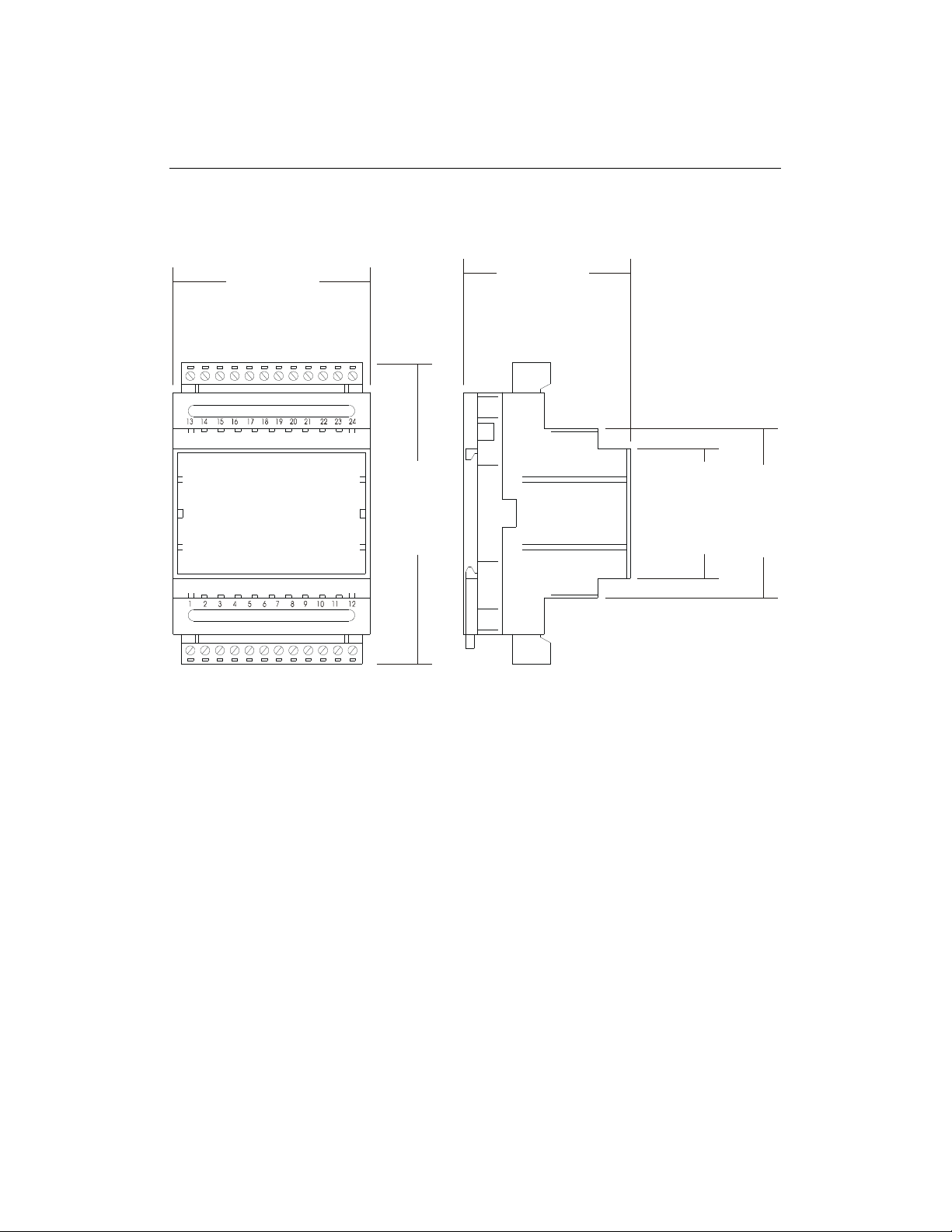
3. Physical Dimensions
The Converter enclosure is shown below. The module has been designed with a quick snapin assembly for mounting onto DIN-rail’s as per DIN EN 50 022.
70.00 mm
106 mm
3.1 Grounding/Shielding
In most cases, the converter will be installed in an enclosure along with other devices which
generate electromagnetic radiation. Examples of these devices are relays and contactors,
transformers, motor controllers etc. This electromagnetic radiation can induce electrical noise
into both power and signal lines, as well as direct radiation into the module causing negative
effects on the system. Appropriate grounding, shielding and other protective steps should be
taken at the installation stage to prevent these effects. These protective steps include control
cabinet grounding, module grounding, cable shield grounding, protective elements for
electromagnetic switching devices, correct wiring as well as consideration of cable types and
their cross sections.
1. Screened twisted pair cable must be used with the screen grounded at one point only.
2. Use should be made of screened I/O, T/C, RTD cable with the screens grounded at one
point as close to the Protocol converter as possible.
8
Page 9
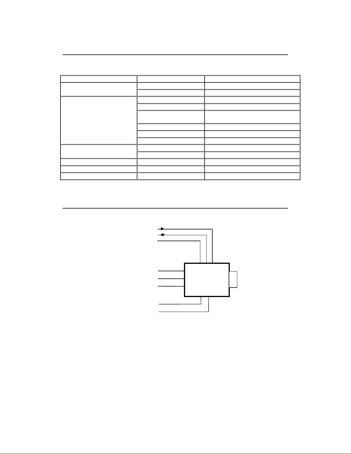
4. Technical Specification
6
Power Supply PC-E 90mA @ 10VDC / 40mA @ 26VDC
10/100 Mbits/s 10/100Base-TX Ethernet
Connector RJ45
Serial
RS232 3 Wire , TX,RX,GND
RS485 2 Wire Multi drop twisted pair
Baud Rate 2400, 4800, 9600, 19200, 38400,
57600, 115200
Data Bits 5, 6, 7, 8.
Parity None, Even, Odd.
Stop Bits 1, 2.
Operating Temperature. -10°C to + 50°C Temperature
Storage Temperature -40°C to + 85°C
Connectors Power and Comms. 8 way screw connector
Humidity Up to 95% non-condensing.
5. Wiring
RS232 - RX DATA
RS232 - TX DATA
RS232 - GND
12 - 24V DC
LOGIC POWER
INPUT
TO RS485
NETWORK
+COMMS
- COMMS
Please Note: You must select RS232 or RS485 on the ip.htm web page
7
8
+
-
E
1
2
3
4
5
PC-E
RJ45
10/100baseTX
9
Page 10
6. Configuration
6.1 Power Connections
The Ethernet/Serial Protocol converter must be clipped onto a DIN rail. Power for the
Protocol converter PC-E must be applied to terminal 1 (+12/24VDC) and terminal 2 (0V).
The power LED will illuminate and all LED's will be off.
6.2 Ethernet Connection
Next the Ethernet connection is required, either through a network or directly to a PC. The
Ethernet interface uses a standard RJ45 connector.
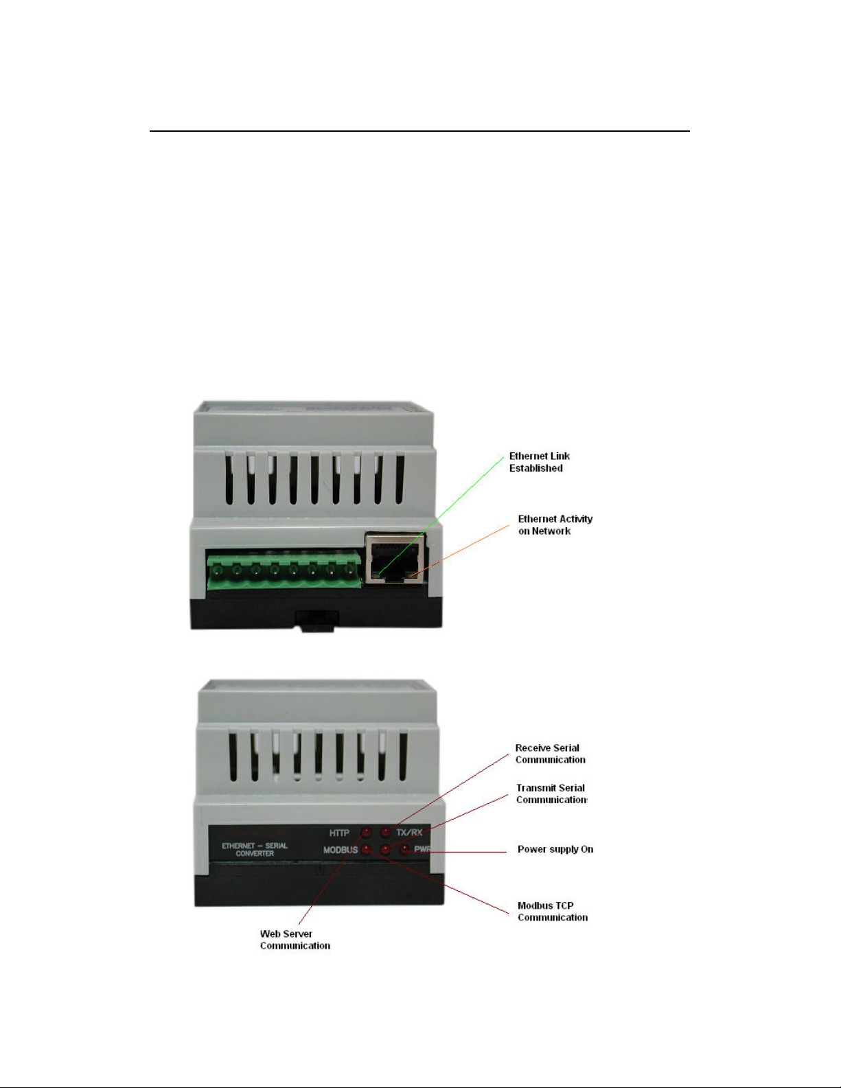
6.3 Indication LED'S
The led's on Protocol converter are used to indicate the operation of the module.
10
Page 11
6.4 Connecting to a PC which is not Connected to a Network
If the PC is equipped with an Ethernet card but not connected to a network, a local
network address should be used for communication between the Converter and the PC.
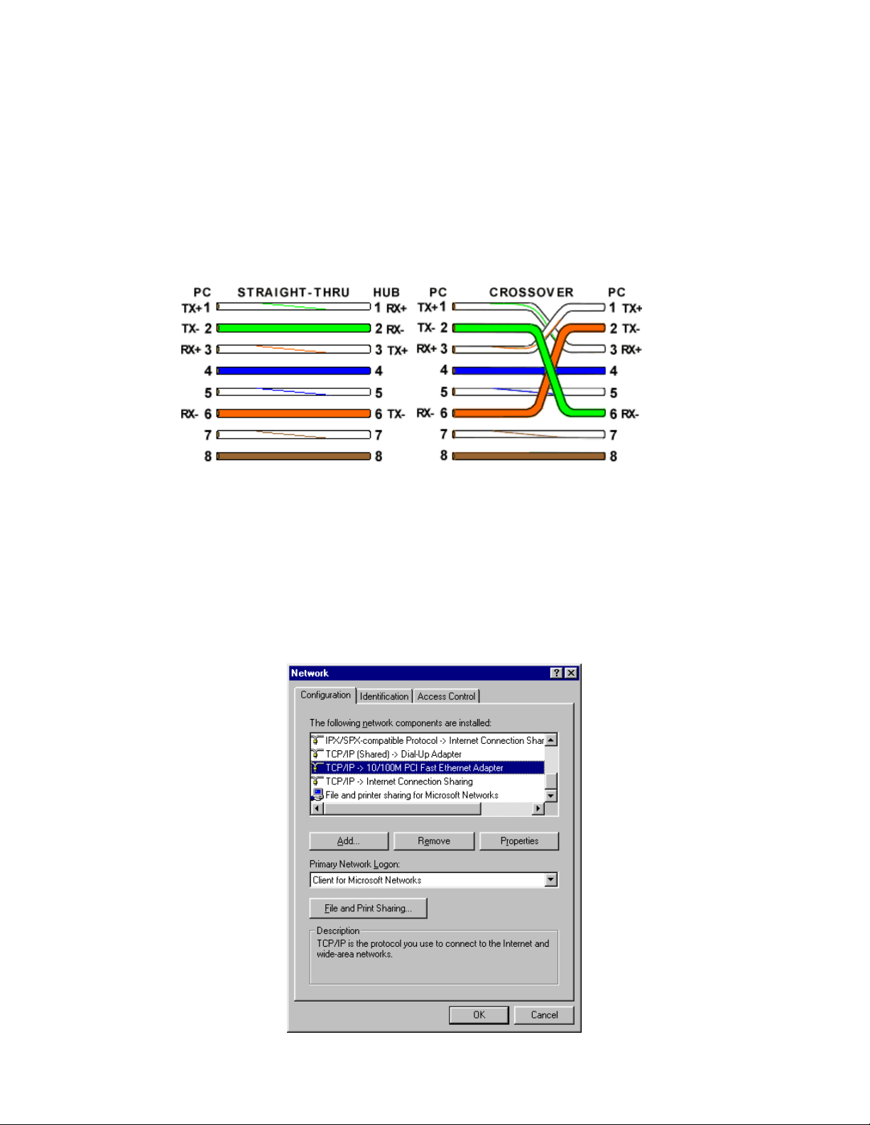
The PC-E converter is shipped with a default IP address 192.168.0.112. For direct
connection between the PC and the Protocol converter, a crossover Ethernet cable is
required.
To setup your PC to connect directly to the Protocol converter PC-E, an IP address in the
same range as the Protocol converter must be assigned to the PC. In Windows
environments, this should be done as follows:
• Connect the PC and the Protocol converter together using a crossover cable
• Open the Windows Control Panel
• Select Network
• Select TCP/IP -> the PC's Ethernet adaptor from the Configuration tab as shown
below
11
Page 12
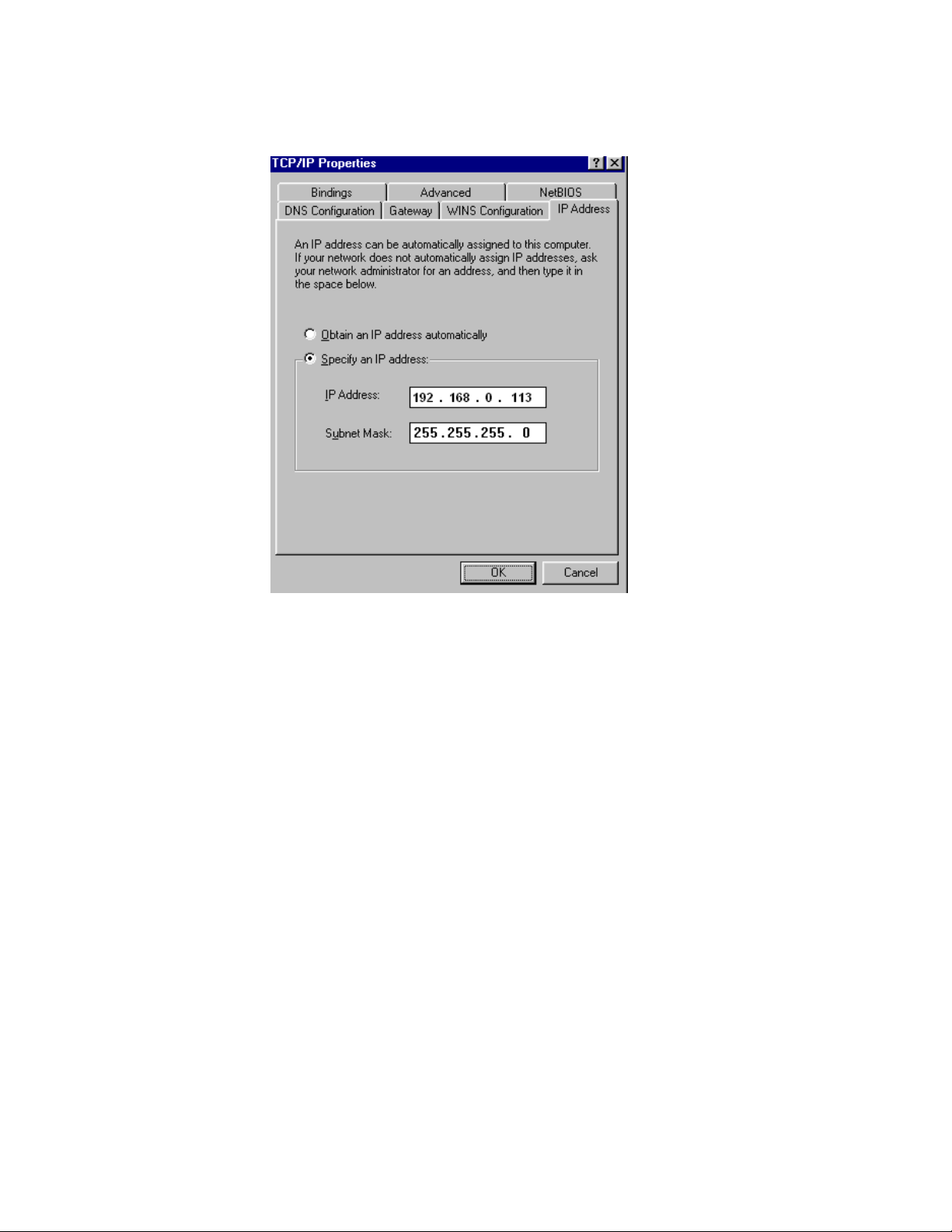
• Click the properties button. A TCP/IP Properties box similar to the one below should
appear
• Select the IP Address tab
• Choose to Specify an IP address as shown in the figure
• Insert the IP address 192.168.0.113 and the corresponding subnet mask as shown
• Save your settings by pressing OK in both TCP/IP properties and Network properties
• Reboot your PC
6.5 Connecting to a PC which is connected to a Network
If there is an Ethernet network available, the Protocol converter can be connected to any hub
belonging to the network. Please note that PC-E is shipped with default IP address of
192.168.0.112. To connect PC-E with existing network first IP address of PC-E should be
changed to free IP address available in the network.
1. Contact system administrator and request for free IP address in the network.
2. Remove LAN cable.
3. Change IP address to the PC as follows...
IP address: 192.168.0.113
Subnet mask: 255.255.255.0
Default Gateway: 192.168.0.1
Enable the network connection.
4. Connect cross over Ethernet cable between PC and PC-E.
5. Apply Power to PC-E
6. Observe that Ethernet link LED, (Green color) is steady on continuously. Right side
LED shows link activity and you can observe slow flash.
12
Page 13
6.6 Testing the Connection
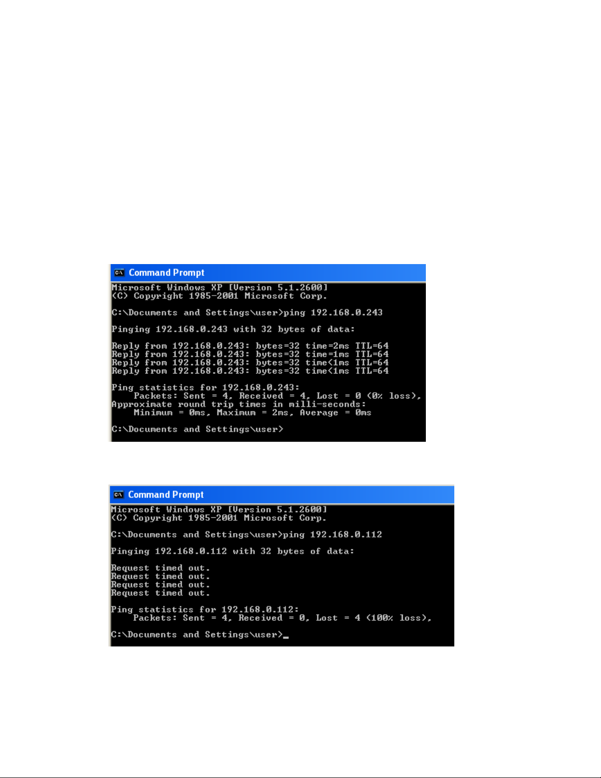
To test the connection between the PC and the Protocol converter, a simple program called
ping can be used. Ping sends a number of messages to the specified IP address and displays
the response. The ping program can be run from the command line or from a DOS prompt on
the PC, as follows:
• Open the Windows Start Menu
• Click Run
• In the Open box, type: "ping 192.168.0.112"
If the network connection is OK between PC and Protocol converter, the program will respond
with:
"Reply from 192.168.0.112" and information about the response time
If there is a problem with the network setup the program will respond as follows...
There may be the following solutions to this problem:
13
Page 14
• Check the Ethernet cable between PC and PC-E. We suggest that it should be cross
over cable. You should not use LAN cable (straight cable) for this purpose. Check
that the Link LED is illuminated when the cable is plugged into the RJ45 connector.
• Make sure that PC is set with default IP address in the range of default IP address of
PC-E. Ex: You can use 192.168.0.113 for the PC.
• If you wish to use LAN cable only between PC and PC-E then make sure that your
PC is set with IP address in the range of PC-E. Set PC with IP address
192.168.0.113, subnet mask: 255.255.255.0.
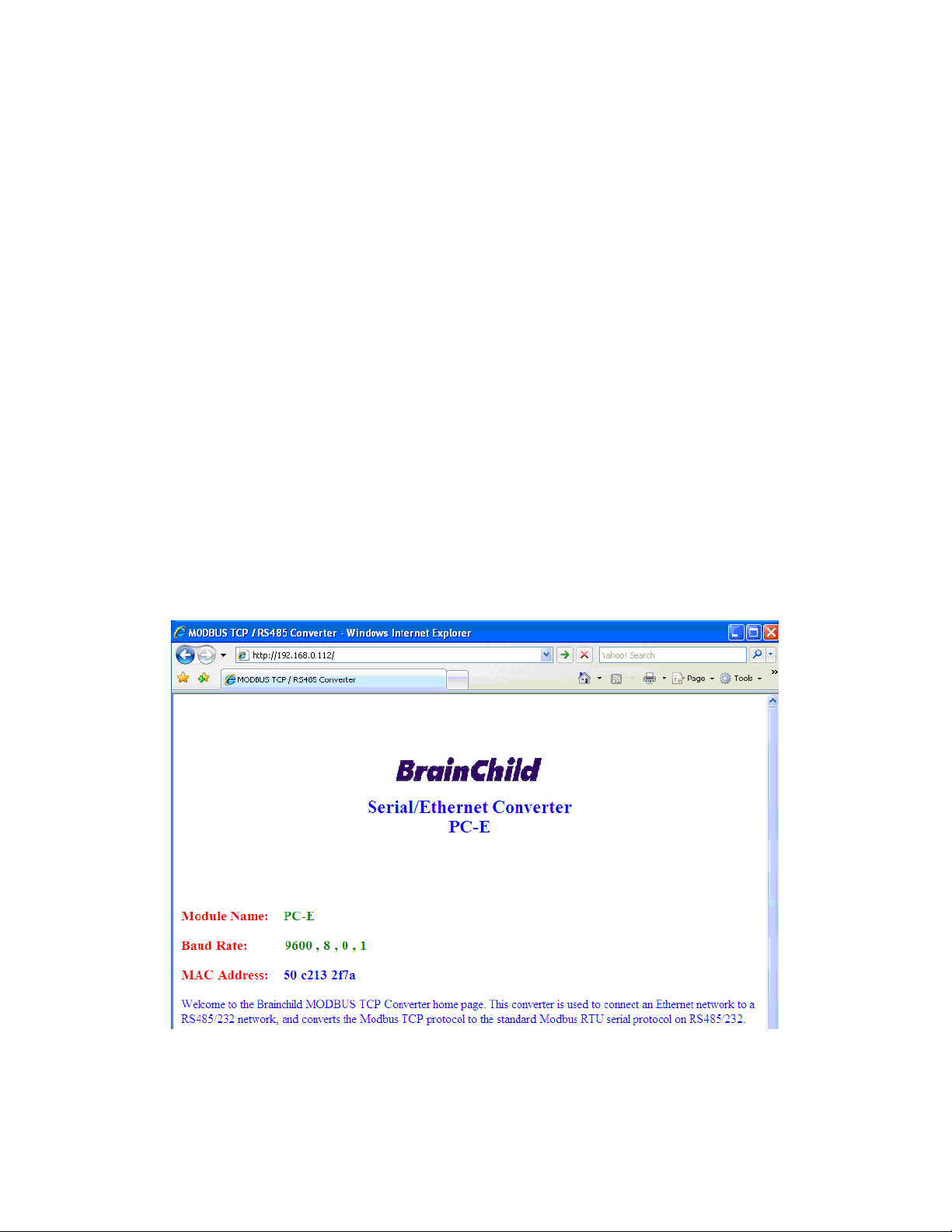
6.7 Viewing Web Pages
The Protocol converter has built in web pages. These are used for changing the configuration.
To view these Web pages, a Web browser such as Internet Explorer or Netscape is needed.
To view the default Web page in Protocol converter, start the Web browser and type
"192.168.0.112" into the address line of the browser window. The main page of the Protocol
converter will now be displayed in the browser window.
If no Web page is displayed, go back to testing the network connection from PC to the
Protocol converter by using the ping command. If the Protocol converter replies to the ping
messages, check the setup of the Web browser. If the Protocol converter is directly
connected to the same network as the PC, "direct connection to the network" or "bypass
proxy server for local addresses" should be selected in the Web browser configuration menu.
If the Protocol converter is connected to the PC through a firewall, a proxy server should be
selected in the configuration menu. Contact the local network administrator for information
about the network configuration.
14
Page 15

6.8 Troubleshooting Guide
No Checkpoint Solution
1
2
3
4
Procedure to set PC-E to default IP address
a. Remove power.
b. Remove "Default IP" jumper.
c. Plug in Ethernet cable and connect to switch.
d. Apply power.
e. After about 2 seconds the link LED should come on and must not flash. (LED closest to
green connector)
f. Replace jumper.
Is the LINK LED on and is
the ACTIVITY LED
flashing with short
Does the Protocol
converter respond to
PING requests?
Can the default Web page
be accessed in a Web
Are the LINK LED and
ACTIVITY LED flashing
together?
pulses?
browser?
No network connection is detected. The Ethernet
cable is either not plugged in or wrong type of
No
cable is used. For connection to a network with a
hub or switch, a straight through network cable
can be used. For direct connection between PC
and Protocol converter, a cross over Ethernet
cable must be used.
A network connection is detected; the Protocol
Yes
converter is connected to the network.
Either the PC or the Protocol converter is setup
with wrong IP address. Set PC-E with default IP
address.
To change the IP address of a PC, use the
Windows "control panel -> network -> TCP/IP
No
properties" and setup an IP address close to the
Protocol converter address. The Protocol
converter is shipped with a default IP address of
192.168.0.112, the PC can be setup with an IP
address of 192.168.0.113
The PC and Protocol converter are setup with a
correct IP address and they are able to
Yes
communicate with each other.
This is normally caused by the setup of the Web
browser.
No
In the "options" or "preferences" menu, check that
the Web browser is configured for direct network
connection or local area network and NOT using a
proxy server.
Yes
No problems.
Yes Switch off the power to PC-E. Wait for some time
before switching on the power for next time.
No No Problems
15
Page 16
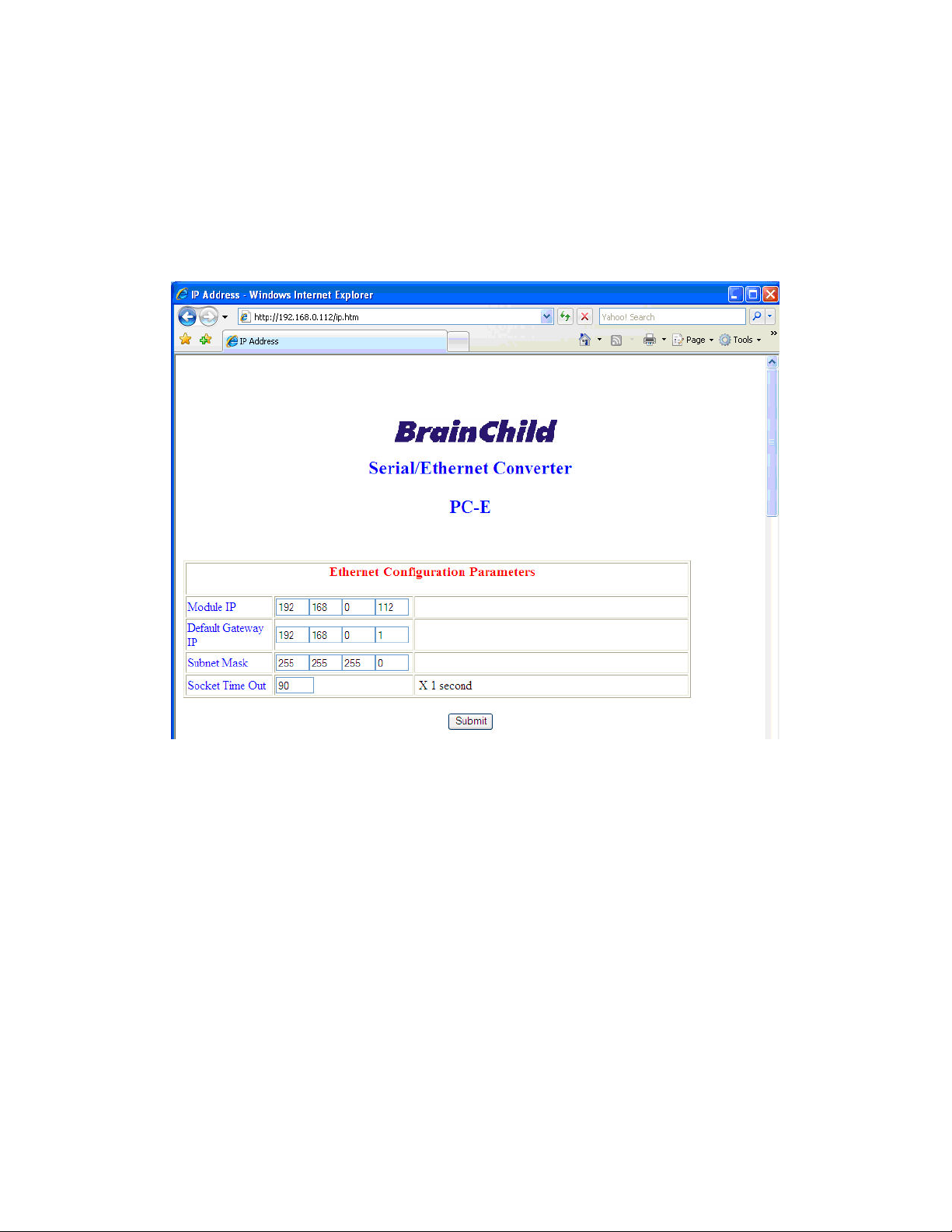
6.9 Parameter Configuration
The Web page address "192.168.0.112/ip.htm" is entered into the address line of the browser
window to access the configuration page. This page allows you to change the IP address of
the Protocol converter, select serial timeout, to setup the baud rate of the Protocol converter
on the RS485 network, and to enter a Module Description Name for
identification/maintenance purposes.
• IP Address: The new IP address can be entered into the web page as shown above.
After this has been done, you must click the Submit button to send the values to the
Protocol converter. The screen will now be updated and if successful will continue to
display the new IP address. The new IP address will only be effective after the
Protocol converter power has been switched off and on again. This feature allows you
to check that the correct IP address has been entered before being activated. If the IP
address has been entered incorrectly and the power has not been switched off, it is
possible to re-enter the correct IP address. Please note that if the power has been
switched off and back on again, the Protocol converter will not communicate until you
enter the new IP address into the address line of the browser window.
• Default Gateway IP Address: A default gateway is a node (a router) on a computer
network that serves as an access point to another network. In enterprises, however,
the gateway is the computer that routes the traffic from a PC to the outside network
that is serving the Web pages. It is only necessary to configure the default gateway
IP address if the PC that is accessing the Converter is on a different network.
16
Page 17
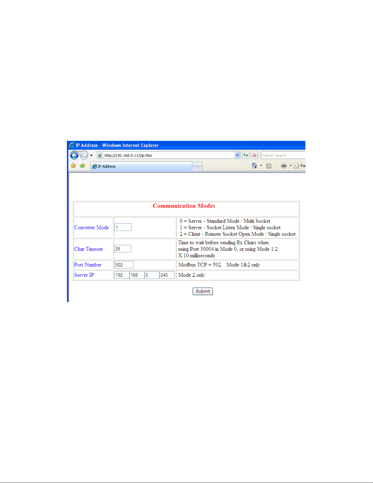
• Subnet Mask: In computer networks, a sub network or subnet is a range of logical
addresses within the address space that is assigned to an organization. The subnet
mask is used to inform the Converter that it must send its replies to the gateway if the
IP address of the PC is on a different network. When the subnet mask is set to
“0.0.0.0” then it is effectively disabled and the default gateway is not used. A typical
subnet mask would be “255.255.255.0”.
• Socket Timeout: If a socket connection is broken, say due to a network fault, it must
timeout to free it up so that it can be used again. This timer is triggered by activity on
the converter, so if there is no communications activity for longer than the timeout
period, the socket will close.
• Converter Mode: These modes have been described in detail in a section 2. Enter 0,
1 or 2 as required. For simple applications, say Data Acquisition Studio software in
PC is Master and IO modules are RTU slaves, then select 1
• Char Timeout: This timeout has been described in detail in a section 2. Enter a value
in 10millisecond increments.
• Port Number: The Port number used to tell the converter that the incoming TCP/UDP
message must get sent to the serial port.
• Server IP: The client converter in mode 2 must connect to the server converter. Enter
the IP address of the server converter in this field.
17
Page 18
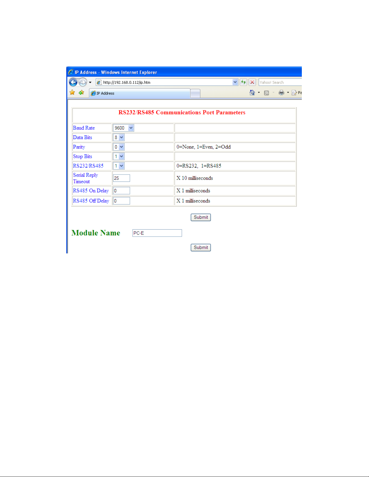
• Baud Rate, Data Bits, Parity, and Stop Bits: The configuration of the serial port can
be configured by selecting the parameters from the pull-down menu. Click on the
Submit button to load these values into the Protocol converter.
• RS232/RS485: This field is used to select RS232 or RS485 on the serial port
• Serial Reply Timeout: This timeout is the time the module waits for a reply from a
slave device. If a reply is received then this timeout is cancelled and the converter
looks for the next TCP message. If the slave does not send a reply, then this timeout
will expire and allow the converter to look for the next TCP message. This timeout
must be longer than the turn-around time of the slave device or it will timeout before
the slave replies. This timeout only operates in Mode 0
• RS485 on Delay: This is the time the RS485 transmitter will be enabled before data
is transmitted. This has no effect on RS232 communications
• RS485 off Delay: This is the time the RS485 transmitter will be enabled after data is
transmitted. This has no effect on RS232 communications
• Module Name: This field allows you to enter a module description name into the
Protocol converter. This is an identifier for diagnostic/maintenance purposes and is
chosen to best describe the Protocol converter in the system by name or number.
18
Page 19

6.10 RS485 termination
Transmission line effects often present a problem on data communication networks. These
problems include reflections and signal attenuation.
To eliminate the presence of reflections from the end of the cable, the cable must be
terminated at both ends with a resistor across the line equal to its characteristic impedance.
Both ends must be terminated since the direction of propagation is bi-directional. In the case
of an RS485 twisted pair cable this termination is typically 120 ohms.
RS485 is designed to be used with a single twisted pair cable. One of the restrictions of this
system is that the common mode voltages of the nodes on the network should not exceed -7V
or +10V. In order to ensure that this condition is met, it is recommended that the 0V
connections on the modules be connected together. For modules that are far apart, a second
twisted pair should be used as the 0V link. On the PC-E terminal 6 (GND) is used as the 0V
connection.
In certain applications where there are strong possibilities of an earth loop being caused by
the 0V link, the link should be tied to the 0V terminal on each module through a 100ohm
resistor, to limit the earth loop current.
Where earth loop problems exist, it may be necessary to isolate the RS485 network using
isolated RS485 repeater
6.11 Setting the Jumpers for the RS485 Termination (J5)
The circuit has got a set of jumpers that can be used to select the termination for the RS485
network. If the jumpers are removed from J5 then no onboard termination will be used and an
external termination must be used.
If J5 is setup as shown below, with J5A(1-2) and J5B(2-3) then a 120ohm active termination
with High Line Idle will be connected to the RS485 network. This is the most commonly used
configuration for RS485 networks.
19
Page 20
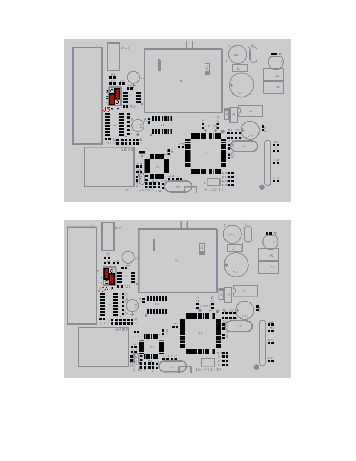
If J5 is setup as shown below, with J5A(2-3) and J5B(1-2) then a 120ohm active termination with Low
Line Idle will be connected to the RS485 network.
20
Page 21

7. Conformity Certificate
DECLARATION OF CONFORMITY
according to EN 45014
Manufacturer’s Name: Brainchild Electronic. Co.Ltd
Manufacturer’s Address: No.209, Chung Yang Road
Nankang district
Taipei, Taiwan
declares that the product
Product Name: Protocol Converter, Serial to Ethernet
Model Number(s): PC-E
complies with EMC Directive 89/336/EEC and Low Voltage Equipment Directive 73/23/EEC and
conforms to the following Product specifications:
Safety: IEC 950
EMC: IEC 61000-4-2-A1 Level 2
IEC 61000-4-3-A1 Level 2
IEC 61000-4-4 Level 3
CISPR 11:1991-A1 / EN 55011:1998 Group 1 Class A
Taiepi, Taiwan May 2007 Mr.Peter Lio
Location Date Vice President
21
Page 22
8. Examples
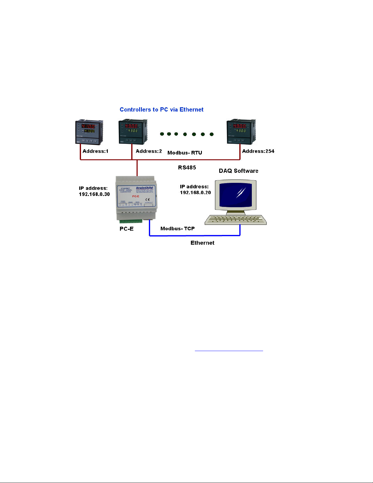
8.1 Controller to DAQ software via PC-E
Sample
Note: Max. 254 controllers can be connected in one RS485 network
PC-E in mode 0 can share data from controllers (Slaves) to max. 4 masters like PC, HMI,
PLC etc..
Procedure
1. First enter IP address of PC as 192.168.0.20
2. Connect cross over Ethernet cable between PC-E to PC. If you are having LAN, connect
straight Ethernet cable between PC-E to PC.
3. Using web browser like internet explorer, type
Now, you can access PC-E configuration via web server
If you are unable to access PC-E web pages, then, there might be problems with
Ethernet cable or default IP address in PC-E or IP address setting in PC
4. Change IP address of PC-E from default 192.168.0.112 to another IP address say
192.168.0.30. Then, click at submit button. Restart the power supply to PC-E converter
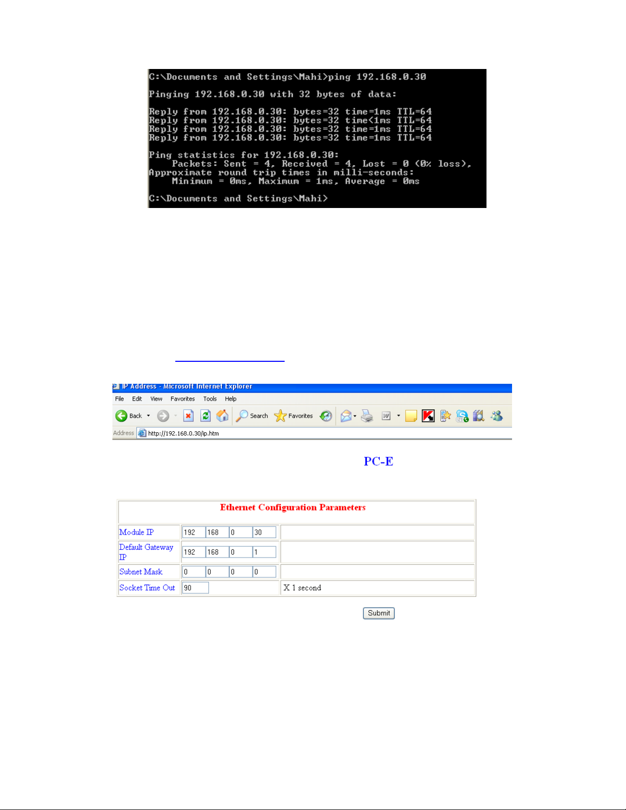
5. Now, using Ping instruction, check if there is good communication between PC-E and PC
http://192.168.0.112/ip.htm
22
Page 23
6. Now, check communication settings in all the controllers. Make sure that address in
RS485 is unique
BTC 4100 Controller
Address: 1
Baud rate: 9600 bps
Data bits:8
Stop bits: 1
Parity: None
7. Now, type
settings at RS485 side as follows
http://192.168.0.30/ip.htm in web browser and configure communication
23
Page 24
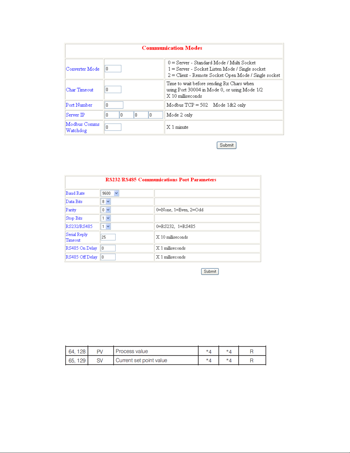
Enter submit button after entering settings as above
8. Then, restart power supply to PC-E converter
9. If you are using BTC 4100, then, check Modbus address for Set point SP and Process
value PV
24
Page 25
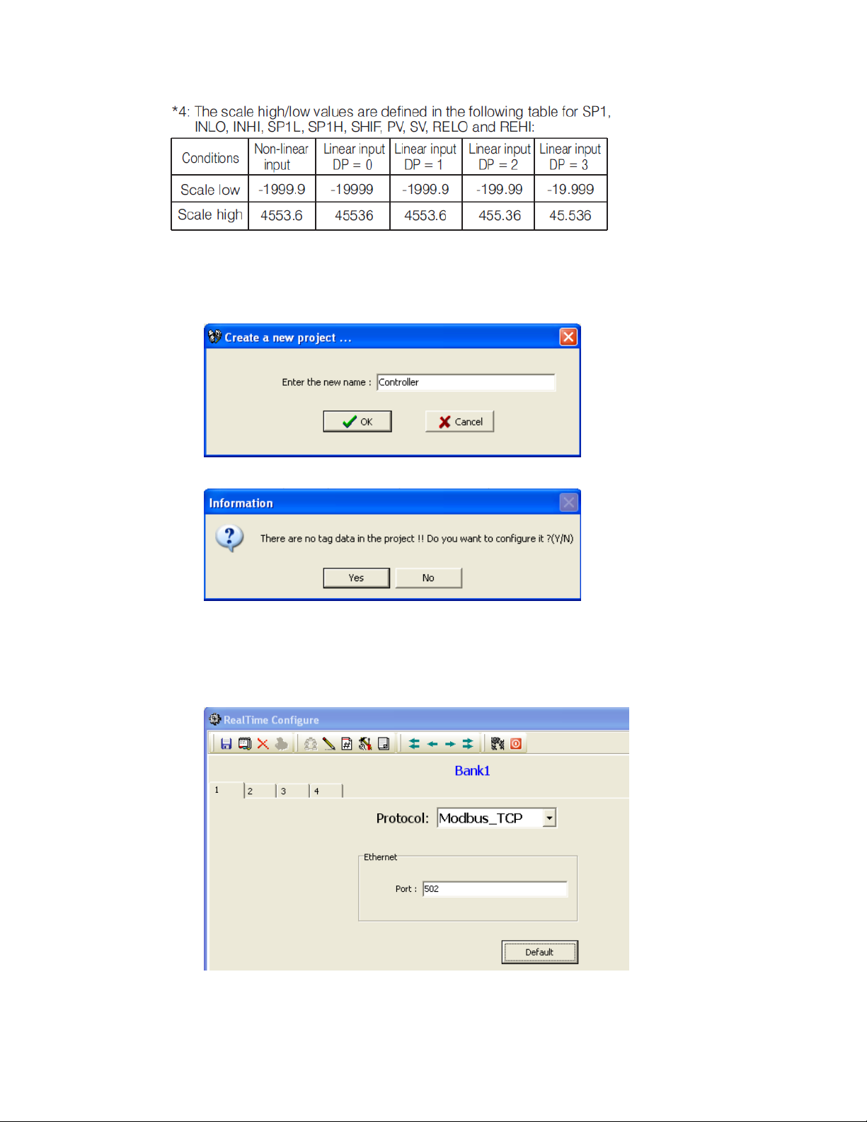
10. Now, if you are using DAQ software, do the following steps
Create a new project
Click at “No”
Make sure bank1 is configured for Modbus_TCP
25
Page 26
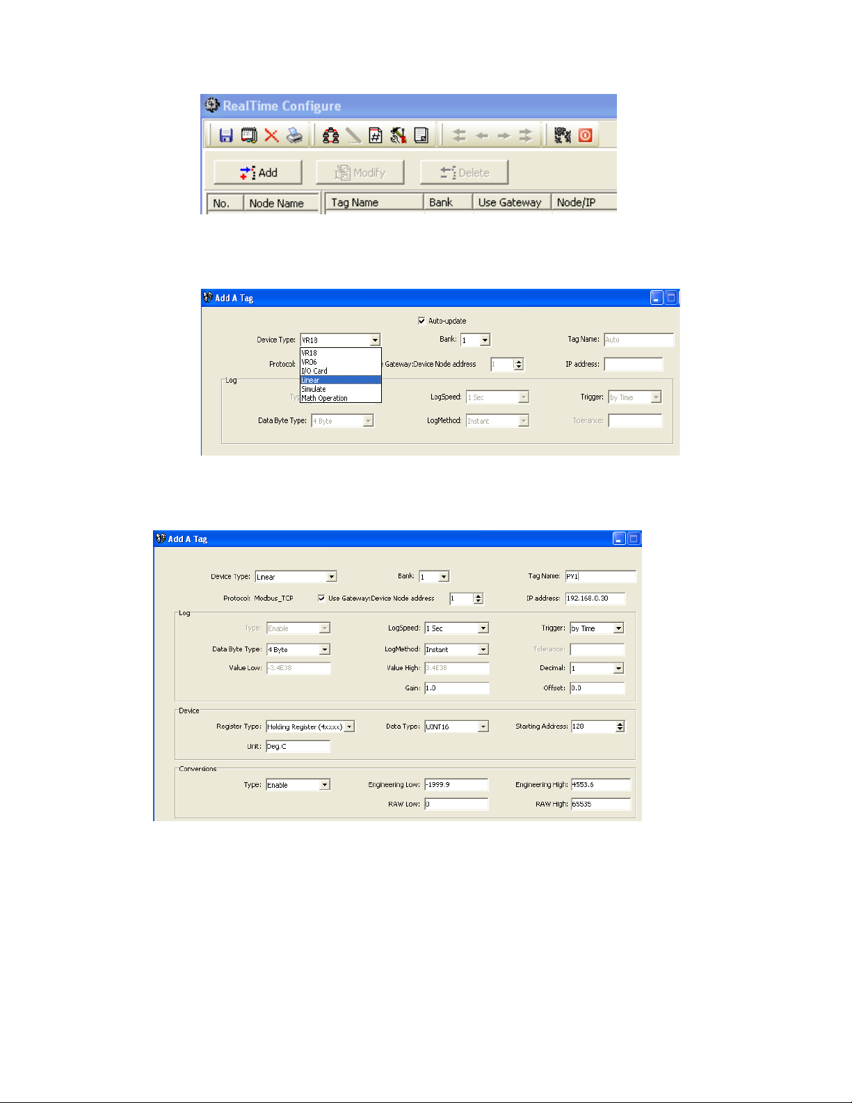
Click at “Add”
Select “Linear”
Enter Bank: 1 (Make sure bank is configured for Modbus TCP)
Enter tag name = PV1
Select “Use Gateway: Device Node address. Select address of controller (This is very
important)
Enter IP address = 192.168.0.30
Register type = Holding register
26
Page 27
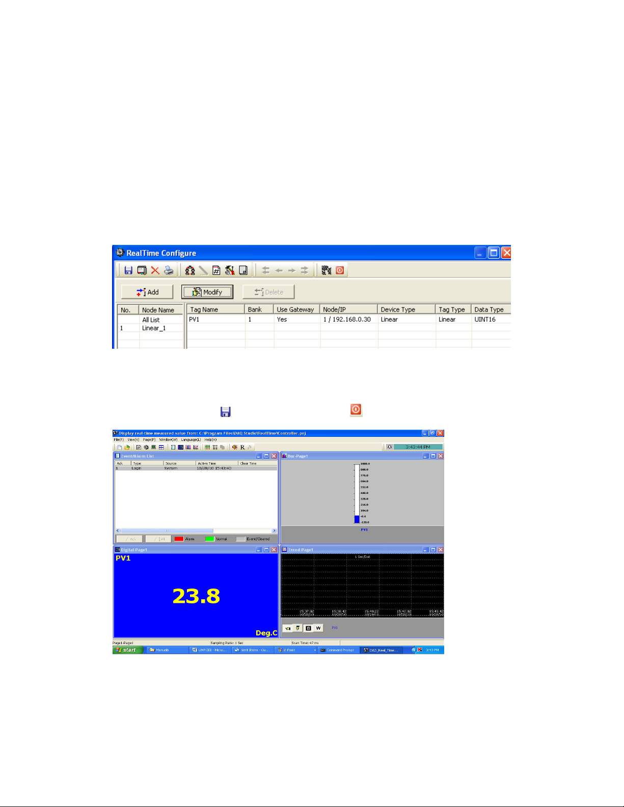
Unit = Deg.C
Starting address = 128
Engineering low = -1999.9
Engineering high = 4553.6
Raw low = 0
Raw high = 65535
Select other selections like log speed, Log method etc.. as per requirement and press “OK”
button
It will add PV1 tag into data base as above
Please do check Node/IP details. It shows address of controller and IP address of PC-E.
Now, click at “Save” icon
, then, click at “Return” icon
Check Scan time and sampling rate at bottom side of screen. Scan time is more than
sampling rate, then, it generates communication error. If there are network delays or
problems with communication settings, you may get communication error. In case if network
delays, it is possible to modify sampling rate in DAQ software and then check again
27
Page 28
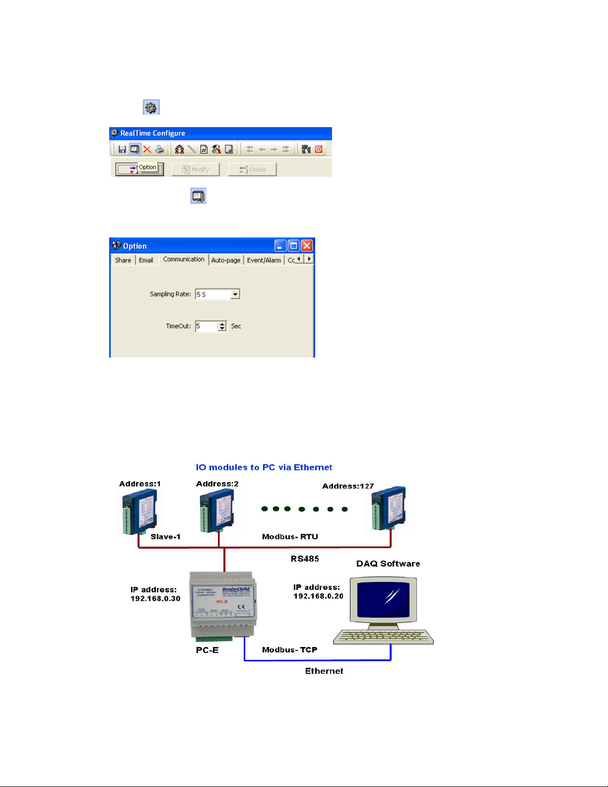
How to change sampling rate
Click at icon
Click at option icon
Select “Communication” tab, then adjust sampling rate and time out. Then, check again
11. Now, similarly add other tags like Set point SP1 etc..
8.2 IO modules to DAQ software via PC-E
Sample
Note: Max. 127 IO modules can be connected in one RS485 network
PC-E can share data from IO modules (Slaves) to max. 4 masters
28
Page 29
Procedure
1. First enter IP address of PC as 192.168.0.20
2. Connect cross over Ethernet cable between PC-E to PC. If you are having LAN, connect
straight Ethernet cable between PC-E to PC.
3. Using web browser like internet explorer, type
http://192.168.0.112/ip.htm
Now, you can access PC-E configuration via web server
If you are unable to access PC-E web pages, then, there might be problems with
Ethernet cable or default IP address in PC-E or IP address setting in PC
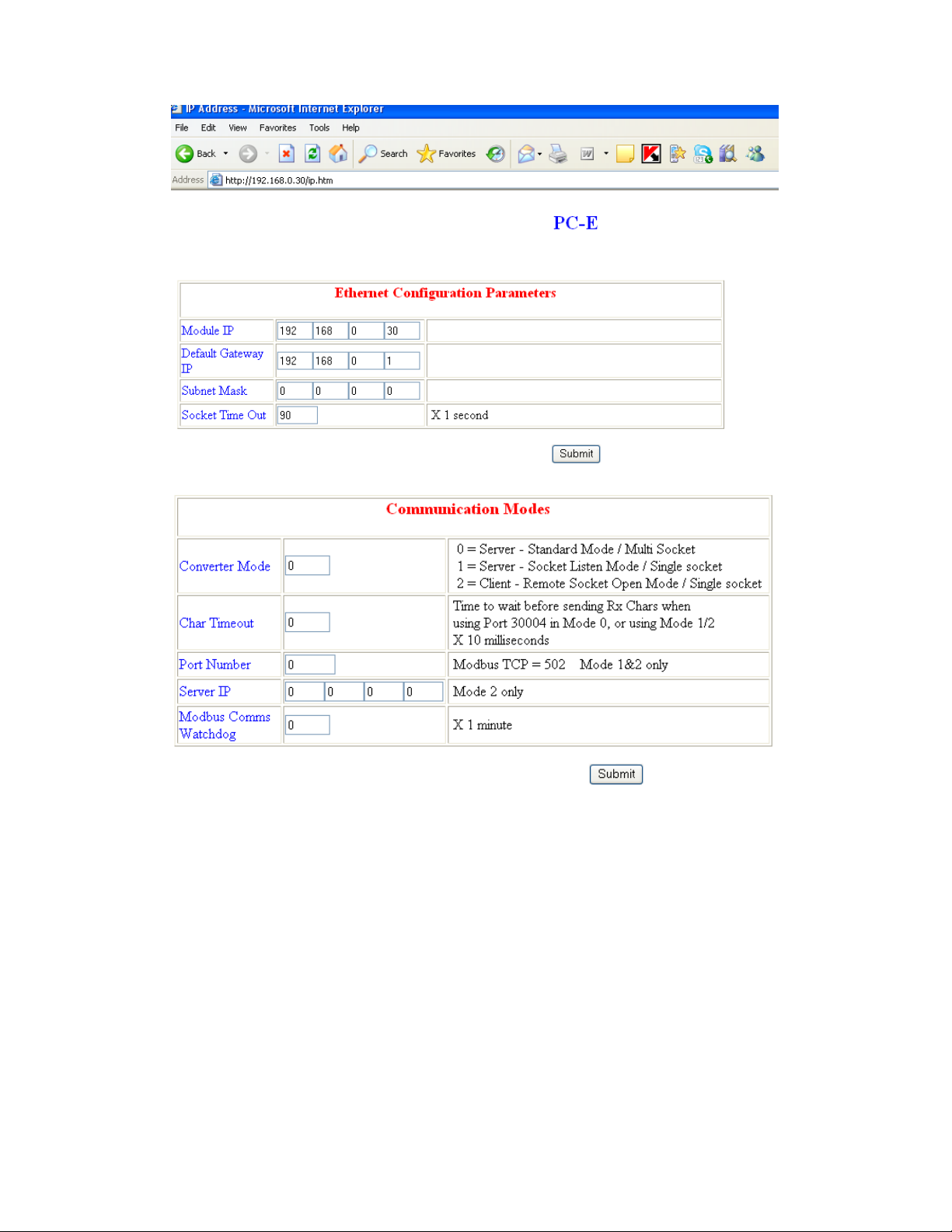
4. Change IP address of PC-E from default 192.168.0.112 to another IP address say
192.168.0.30. Then, click at submit button. Restart the power supply to PC-E converter
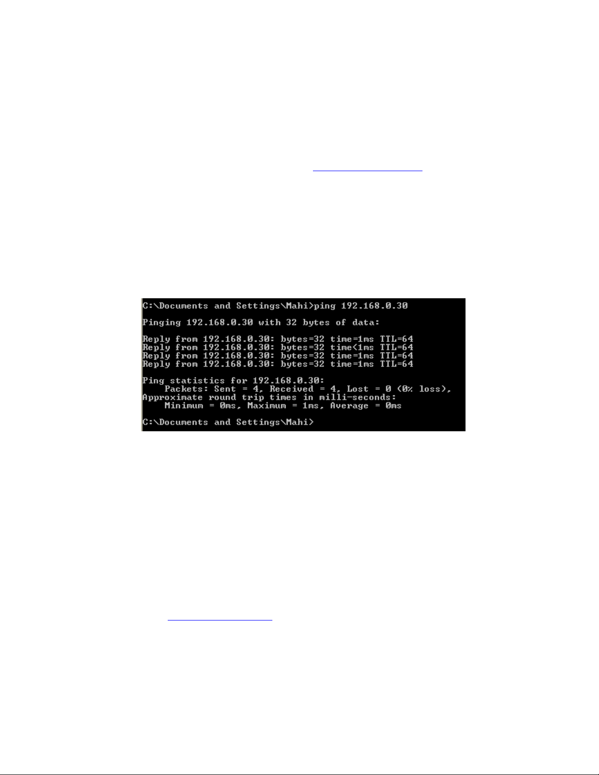
5. Now, using Ping instruction, check if there is good communication between PC-E and PC
6. Now, check communication settings in all the IO modules. For checking purpose, first
make sure that Dip switch 9 = OFF in IO module for default communication settings
address in
Make sure address of IO modules in RS485 is unique
IO module, IO-6RTD
Dip switch 2 = ON, all other dip switches are OFF
Address: 2
Baud rate: 9600 bps
Data bits: 8
Stop bits: 1
Parity: None
7. Now, type
http://192.168.0.30/ip.htm in web browser and configure communication
settings at RS485 side as follows
29
Page 30
30
Page 31
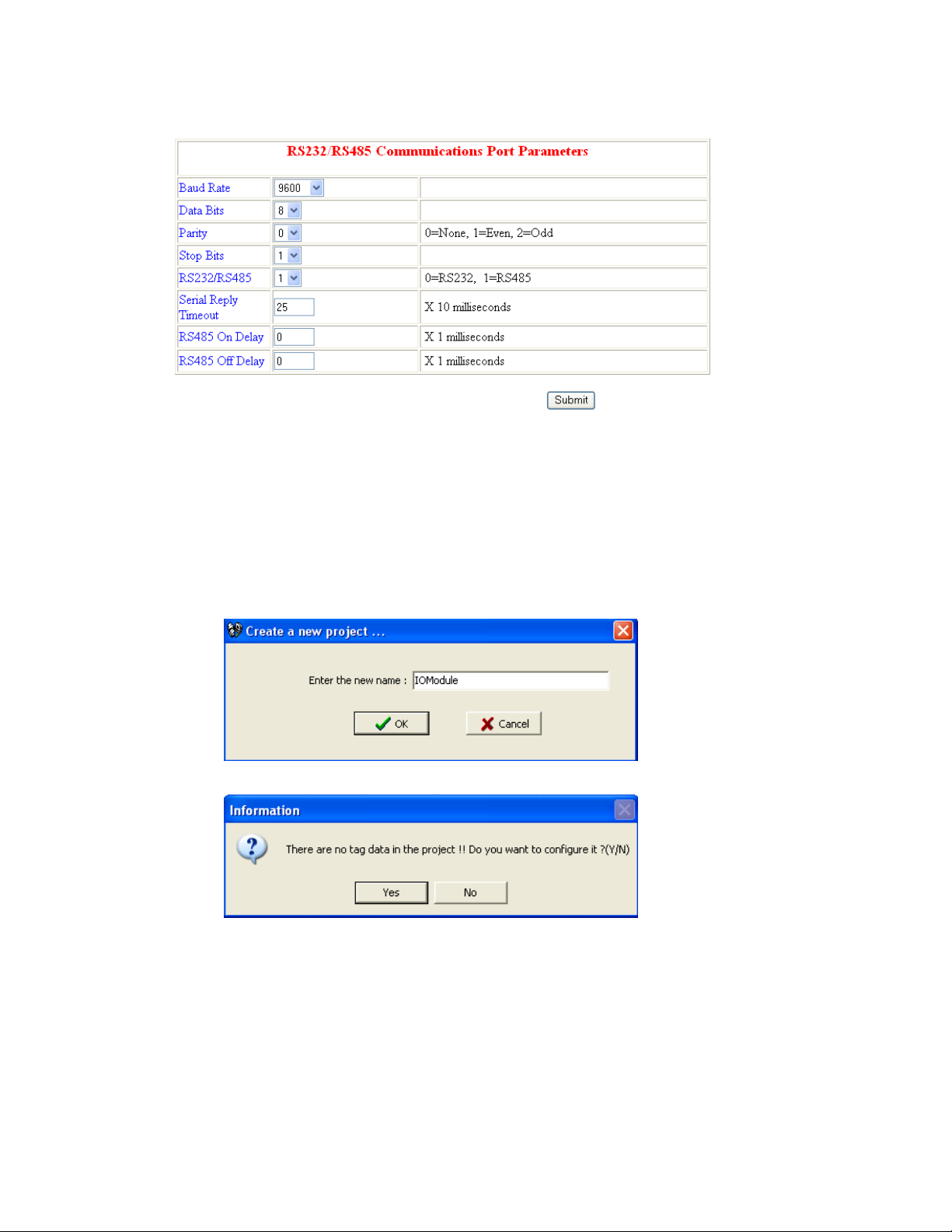
Enter submit button after entering settings as above
8. Then, restart power supply to PC-E converter
9. If you are using DAQ software, do the following steps
Create a new project
Click at “No”
Make sure bank1 is configured for Modbus_TCP
31
Page 32
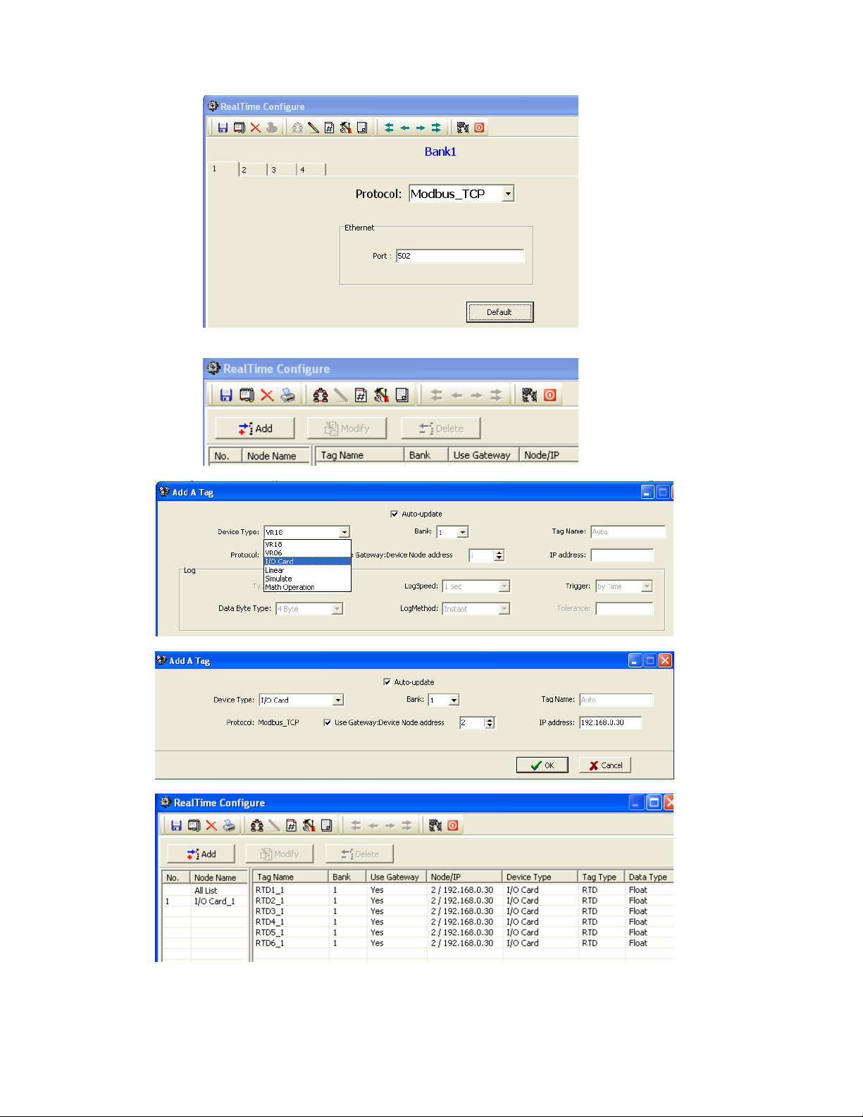
If all wiring and configurations are correct, IO module data base will be added into DAQ
software automatically. If there is error, it requires to re check the following
32
Page 33
Address of IO module
Dip switches of IO module
Connection between IO module to PC-E
Configuration of PC-E
Ethernet cable between PC-E and PC
IP address of PC-E and PC
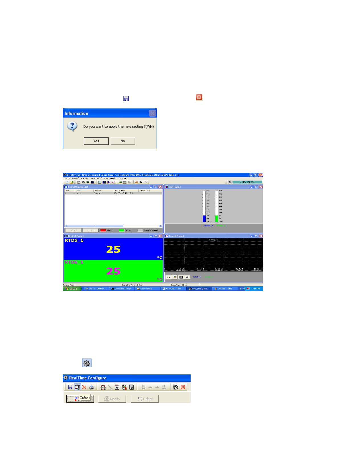
Please do check Node/IP details. It shows address of IO module and IP address of PC-E.
Now, click at “Save” icon
, then, click at “Return” icon
Click at “Yes”
Then, it will show temperature values of IO-6RTD module
Check Scan time and sampling rate at bottom side of screen. Scan time is more than
sampling rate, then, it generates communication error. If there are network delays or
problems with communication settings, you may get communication error. In case if network
delays, it is possible to modify sampling rate in DAQ software and then check again
How to change sampling rate
Click at
icon
33
Page 34
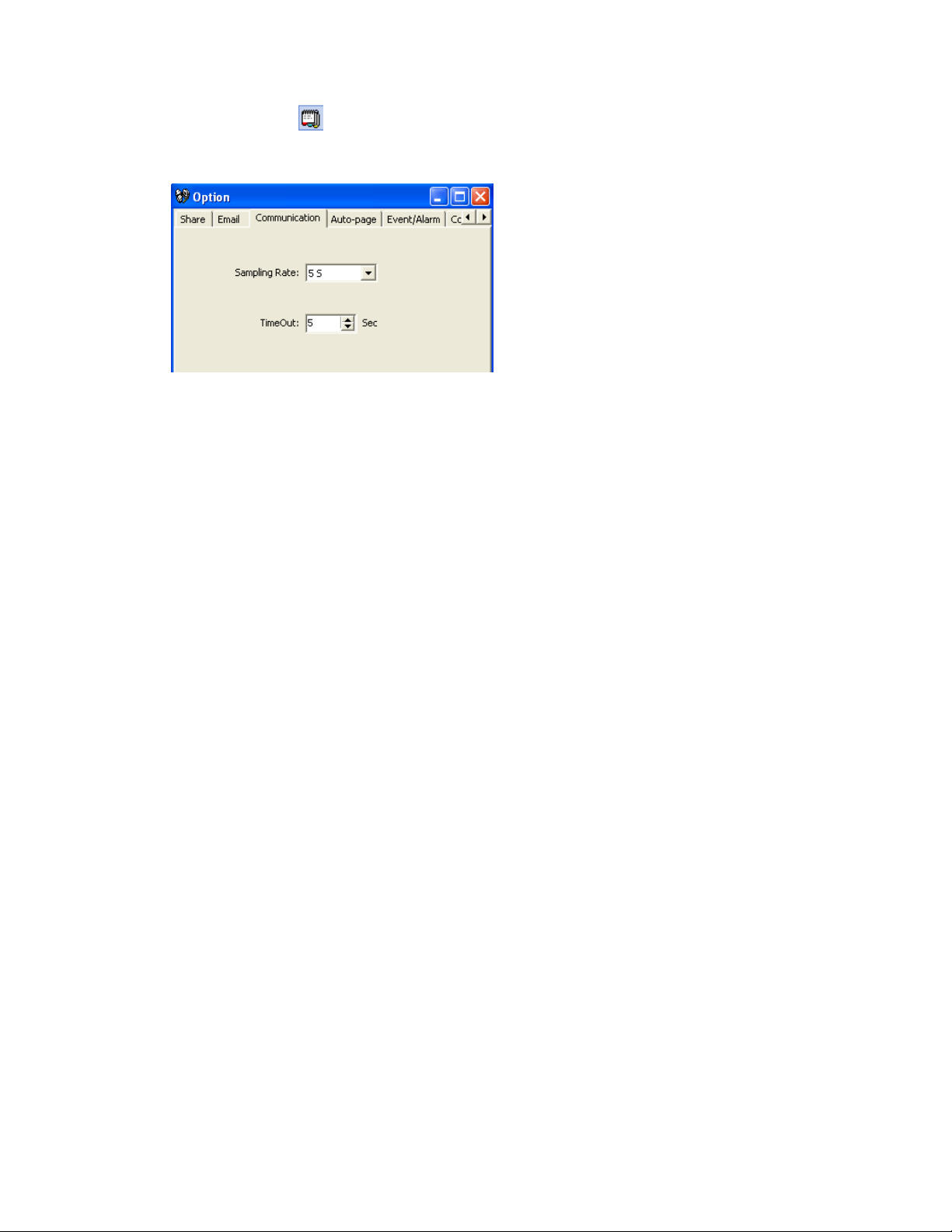
Click at option icon
Select “Communication” tab, then adjust sampling rate and time out. Then, check again
34
 Loading...