

Page 1
User's ManualUser's Manual
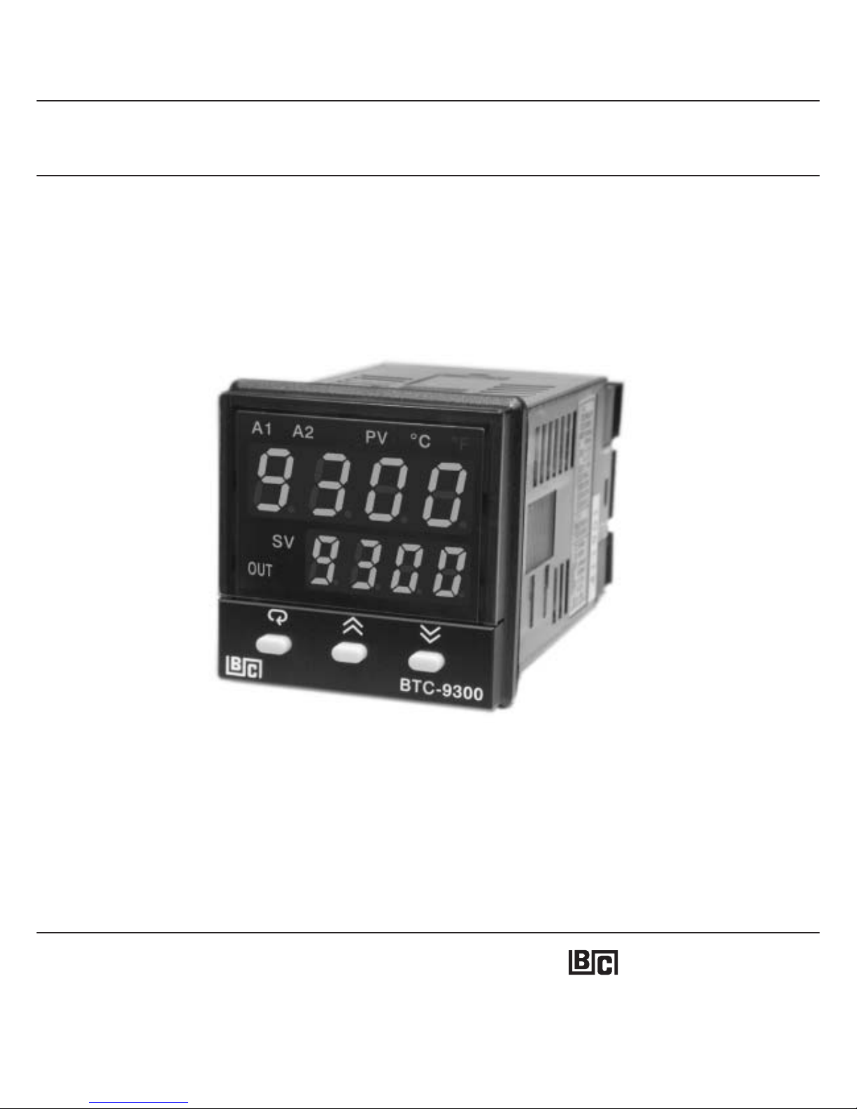
BTC-9300
Self-Tune Fuzzy / PID
Process / Temperature Controller
BTC-9300
Self-Tune
Fuzzy / PID
Process
/ Temperature Controller
BRAINCHILD
UM93001C
Page 2

2
UM93001C
Warning SymbolWarning Symbol
Use the ManualUse the Manual
The Symbol calls attention to an operating procedure, practice, or the like, which, if not correctly performed or
adhered to, could result in personal injury or damage to or destruction of part or all of the product and system.
Do not proceed beyond a warning symbol until the indicated conditions are fully understood and met.
The Symbol calls attention to an operating procedure, practice, or the like, which, if not correctly performed or
adhered
to, could result in personal injury or damage to or destruction of part or all of the product and system.
Do
not proceed beyond a warning symbol until the indicated conditions are fully understood and met.
Installers
Basic Function User
Enhanced Function User
System Designer
Expert User
Installers
Basic
Function User
Enhanced
Function User
System
Designer
Expert
User
Read Chapter 1, 2
Read Chapter 1, 3, 5
Read Chapter 1, 3, 4, 5
Read All Chapters
Read Page 11
Read Chapter 1, 2
Read
Chapter 1, 3, 5
Read
Chapter 1, 3, 4, 5
Read
All Chapters
Read
Page 11
Page 3

3
UM93001C
CONTENTS
Chapter 1 OverviewChapter 1 Overview
1-1 Features
1-2 Ordering Code
1-3 Programming Port and DIP Switch
1-4 Keys and Displays
1-5 Menu Overview
1-6 System Modes
1-7 Parameter Description
1-1 Features
1-2
Ordering Code
1-3
Programming Port and DIP Switch
1-4
Keys and Displays
1-5
Menu Overview
1-6
System Modes
1-7
Parameter Description
Page NoPage No Page NoPage No
Chapter 2 InstallationChapter 2 Installation
2-1 Unpacking
2-2 Mounting
2-3 Wiring Precautions
2-4 Power Wiring
2-5 Sensor Installation Guidelines
2-6 Thermocouple Input Wiring
2-7 RTD Input Wiring
2-8 Linear DC Input Wiring
2-9 CT / Heater Current Input Wiring
2-10 Event Input wiring
2-11 Output 1 Wiring
2-12 Output 2 Wiring
2-13 Alarm 1 Wiring
2-14 Alarm 2 Wiring
2-15 RS-485
2-16 RS-232
2-17 Analog Retransmission
2-18 Programming Port
2-1 Unpacking
2-2
Mounting
2-3
Wiring Precautions
2-4
Power Wiring
2-5
Sensor Installation Guidelines
2-6
Thermocouple Input Wiring
2-7
RTD Input Wiring
2-8
Linear DC Input Wiring
2-9
CT / Heater Current Input Wiring
2-10
Event Input wiring
2-11
Output 1 Wiring
2-12
Output 2 Wiring
2-13
Alarm 1 Wiring
2-14
Alarm 2 Wiring
2-15
RS-485
2-16
RS-232
2-17
Analog Retransmission
2-18
Programming Port
Chapter 3 Programming the Basic FunctionChapter 3 Programming the Basic Function
3-1 Input 1
3-2 OUT1 & OUT2 Types
3-3 Rearrange User Menu
3-4 Heat Only Control
3-5 Cool Only Control
3-6 Heat - Cool Control
3-7 Dwell Timer
3-8 Process Alarms
3-9 Deviation Alarms
3-10 Deviation Band Alarms
3-11 Heater Break Alarm
3-12 Loop Break Alarm
3-13 Sensor Break Alarm
3-14 SP1 Range
3-15 PV1 Shift
3-16 Failure Transfer
3-17 Bumpless Transfer
3-18 Self-tuning
3-19 Auto-tuning
3-20 Manual Tuning
3-1 Input 1
3-2
OUT1 & OUT2 Types
3-3
Rearrange User Menu
3-4
Heat Only Control
3-5
Cool Only Control
3-6
Heat - Cool Control
3-7
Dwell Timer
3-8
Process Alarms
3-9
Deviation Alarms
3-10
Deviation Band Alarms
3-11
Heater Break Alarm
3-12
Loop Break Alarm
3-13
Sensor Break Alarm
3-14
SP1 Range
3-15
PV1 Shift
3-16
Failure Transfer
3-17
Bumpless Transfer
3-18
Self-tuning
3-19
Auto-tuning
3-20
Manual Tuning
Chapter 4 Programming the Full FunctionChapter 4 Programming the Full Function
4-1 Event Input
4-2 Second Set Point
4-3 Second PID Set
4-4 Ramp & Dwell
4-5 Remote Set Point
4-6 Differential Control
4-7 Output Power Limits
4-8 Data Communication
4-9 Analog Retransmission
4-10 Digital Filter
4-11 Sleep Mode
4-12 Pump Control
4-13 Remote Lockout
4-1 Event Input
4-2
Second Set Point
4-3
Second PID Set
4-4
Ramp & Dwell
4-5
Remote Set Point
4-6
Differential Control
4-7
Output Power Limits
4-8
Data Communication
4-9
Analog Retransmission
4-10
Digital Filter
4-11
Sleep Mode
4-12
Pump Control
4-13
Remote Lockout
Chapter 5 ApplicationsChapter 5 Applications
5-1 Pump / Pressure Control
5-2 Variable Period Full Wave SSR ( VPFW SSR )
5-3 Heat Only Control
5-4 Cool Only Control
5-5 Heat - Cool Control
5-6 Ramp & Dwell
5-7 Remote Set Point
5-8 Differential Control
5-9 Dual Set Point / PID
5-10 RS-485
5-11 RS-232
5-12 Retransmit
5-1 Pump / Pressure Control
5-2
Variable Period Full Wave SSR ( VPFW SSR )
5-3
Heat Only Control
5-4
Cool Only Control
5-5
Heat - Cool Control
5-6
Ramp & Dwell
5-7
Remote Set Point
5-8
Differential Control
5-9
Dual Set Point / PID
5-10
RS-485
5-11
RS-232
5-12
Retransmit
Chapter 6 CalibrationChapter 6 Calibration
Appendix
Chapter 7 Error Codes & Troubleshooting
Chapter 7 Error Codes & Troubleshooting
Chapter 8 SpecificationsChapter 8 Specifications
A-1 Menu Existence Conditions
A-2 Factory Menu Description
A-3 Glossary
A-4 Index
A-5 Memo
A-6 Warranty
A-1 Menu Existence Conditions
A-2
Factory Menu Description
A-3
Glossary
A-4
Index
A-5
Memo
A-6
Warranty
3-21 Signal Conditioner DC Power Supply
3-22 Manual Control
3-23 Display Mode
3-24 Heater Current Monitoring
3-25 Reload Default Values
3-21 Signal Conditioner DC Power Supply
3-22
Manual Control
3-23
Display Mode
3-24
Heater Current Monitoring
3-25
Reload Default Values
65
64
66
67
67
68
69
70
71
73
74
75
76
77
78
79
80
81
68
69
70
71
73
74
75
76
77
78
79
80
81
82
84
86
87
88
90
92
93
94
96
98
99
82
84
86
87
88
90
92
93
94
96
98
99
100
104
107
110
113
115
122
125
127
110
113
115
122
125
127
4
7
8
9
11
12
13
4
7
8
9
11
12
13
21
21
22
23
24
25
26
26
28
29
30
32
34
35
36
37
38
39
21
21
22
23
24
25
26
26
28
29
30
32
34
35
36
37
38
39
40
41
42
43
44
45
47
48
50
51
52
53
54
54
55
56
57
58
59
61
40
41
42
43
44
45
47
48
50
51
52
53
54
54
55
56
57
58
59
61
Page 4

Chapter 1 OverviewChapter 1 Overview
1 1 Features1 1 Features
BTC-9300 Fuzzy Logic plus PID microprocessor-based controller, incorporates a bright,
easy to read 4-digit LED display, indicating process value. The technology
enables a process to reach a predetermined set point in the shortest time, with the
minimum of overshoot during power-up or external load disturbance. The units are
housed in a 1/16 DIN case, measuring 48 mm x 48 mm with 75 mm behind panel depth.
The units feature three touch keys to select the various control and input parameters.
Using a unique function, you can put at most 5 parameters in front of user menu by using
contained in the setup menu. This is particularly useful to OEM's asitiseasy
to configure menu to suit the specific application.
Fuzzy Logic
SEL1 to SEL5
BTC-9300 Fuzzy Logic plus PID microprocessor-based controller, incorporates a bright,
easy to read 4-digit LED display, indicating process value. The technology
enables a process to reach a predetermined set point in the shortest time, with the
minimum of overshoot during power-up or external load disturbance. The units are
housed in a 1/16 DIN case, measuring 48 mm x 48 mm with 75 mm behind panel depth.
The units feature three touch keys to select the various control and input parameters.
Using a unique function, you can put at most 5 parameters in front of user menu by using
contained in the setup menu. This is particularly useful to OEM's asitiseasy
to configure menu to suit the specific application.
Fuzzy Logic
SEL1 to SEL5
BTC-9300 is powered by 11-26 VAC/VDC or 90 - 264 V AC supply, incorporating a 2 amp.
control relay output and dual 2 amp. alarm relays output as standard whereby second
alarm can be exceptionally configured into second output for cooling purpose or dwell
timer. Alternative output options include SSR drive, triac, 4 - 20 mA and0-10volts. BTC9300 is fully programmable for PT100, thermocouple types J, K, T, E, B, R, S, N, L, 0 20mA, 4 -20mA andvoltage signal input, withno need tomodify the unit. Theinput signals
are digitized by using a converter. Its allows the BTC-9300
to control fast processes such as pressure and flow. is incorporated. The selftune can be used to optimize the control parameters as soon as undesired control result
is observed. Unlike auto-tune, Self-tune will produce less disturbance to the process
during tuning, and can be used any time.
18-bit A to D fast sampling rate
Self tune
BTC-9300 is powered by 11-26 VAC/VDC or 90 - 264 V AC supply, incorporating a 2 amp.
control relay output and dual 2 amp. alarm relays output as standard whereby second
alarm can be exceptionally configured into second output for cooling purpose or dwell
timer. Alternative output options include SSR drive, triac, 4 - 20 mA and 0 - 10 volts. BTC9300 is fully programmable for PT100, thermocouple types J, K, T, E, B, R, S, N, L, 0 20mA, 4 -20mA andvoltage signal input, withno need tomodify the unit. Theinput signals
are digitized by using a converter. Its allows the BTC-9300
to control fast processes such as pressure and flow. is incorporated. The selftune can be used to optimize the control parameters as soon as undesired control result
is observed. Unlike auto-tune, Self-tune will produce less disturbance to the process
during tuning, and can be used any time.
18-bit A to D fast sampling rate
Self tune
High accuracy 18-bit input A D
High accuracy 15-bit output D A
Fast input sample rate ( 5 times / second)
Two function complexity levels
User menu configurable
Pump control
Fuzzy + PID microprocessor-based control
Automatic programming
Differential control
Auto-tune function
Self-tune function
Sleep mode function
" Soft-start " ramp and dwell timer
Programmable inputs( thermocouple, RTD, mA, VDC )
Analog input for remote set point and CT
Event input for changing function & set point
Programmable digital filter
Hardware lockout + remote lockout protection
Loop break alarm
Heater break alarm
Sensor break alarm + Bumpless transfer
RS-485, RS-232 communication
Analog retransmission
Signal conditioner DC power supply
A wide variety of output modules available
Safety UL / CSA / IEC1010 1
EMC / CE EN61326
Front panel sealed to NEMA 4X & IP65
High accuracy 18-bit input A D
High
accuracy 15-bit output D A
Fast
input sample rate ( 5 times / second)
Tw o
function complexity levels
User
menu configurable
Pump
control
Fuzzy
+ PID microprocessor-based control
Automatic
programming
Differential
control
Auto-tune
function
Self-tune
function
Sleep
mode function
"
Soft-start " ramp and dwell timer
Programmable
inputs( thermocouple, RTD, mA, VDC )
Analog
input for remote set point and CT
Event
input for changing function & set point
Programmable
digital filter
Hardware
lockout + remote lockout protection
Loop
break alarm
Heater
break alarm
Sensor
break alarm + Bumpless transfer
RS-485,
RS-232 communication
Analog
retransmission
Signal
conditioner DC power supply
A
wide variety of output modules available
Safety
UL / CSA / IEC1010 1
EMC
/ CE EN61326
Front
panel sealed to NEMA 4X & IP65
Unique
Valuable
Unique
Valuable
4
UM93001D
Page 5

In last nearly a hundred years although PID control has been used and proved to be an
efficient controlling method by many industries, yet the PID is difficult to deal with some
sophisticated systems such assecond and higher order systems, long time-lag systems,
during set point change and/or load disturbance circumstance etc. The PID principle is
based on a mathematic modeling which is obtained by tuning the process. Unfortunately ,
many systems are too complex to describe in numerical terms precisely. In addition,
these systems may be variable from time to time. In order to overcome the imperfection
of PID control, the Fuzzy Technology is introduced. What is the Fuzzy Control ? It works
like a good driver. Under different speeds and circumstances, he can control a car well
with experiences he had before and does not require the knowledge of kinetic theory of
motion. The Fuzzy Logic is a linguistic control which is different from the numerical PID
control. It controls the system by experiences and does not need to simulate the system
precisely as been controlled by PID.
In last nearly a hundred years although PID control has been used and proved to be an
efficient controlling method by many industries, yet the PID is difficult to deal with some
sophisticated systems such assecond and higher order systems, long time-lag systems,
during set point change and/or load disturbance circumstance etc. The PID principle is
based on a mathematic modeling which is obtained by tuning the process. Unfortunately ,
many systems are too complex to describe in numerical terms precisely. In addition,
these systems may be variable from time to time. In order to overcome the imperfection
of PID control, the Fuzzy Technology is introduced. What is the Fuzzy Control ? It works
like a good driver. Under different speeds and circumstances, he can control a car well
with experiences he had before and does not require the knowledge of kinetic theory of
motion. The Fuzzy Logic is a linguistic control which is different from the numerical PID
control. It controls the system by experiences and does not need to simulate the system
precisely as been controlled by PID.
UM93001C
5
Digital communications RS-485, RS-232 or 4 - 20 mA retransmission are available as an
additional option. These options allow BTC-9300 tobe integrated withsupervisory control
system and software, or alternatively drive remote display, chart recorders or dataloggers.
Digital communications RS-485, RS-232 or 4 - 20 mA retransmission are available as an
additional option. These options allow BTC-9300 tobe integrated withsupervisory control
system and software, or alternatively drive remote display, chart recorders or dataloggers.
Three kinds 1.
2.
3.
of method can be used to program BTC-9300. Use keys on front panel
to program the unit manually, Use a PC and setup software to program the unit via
RS-485 or RS-232 COMM port and Use P10A, a hand-held programmer, to program
the unit via programming port.
Three kinds 1.
2.
3.
of method can be used to program BTC-9300. Use keys on front panel
to program the unit manually, Use a PC and setup software to program the unit via
RS-485 or RS-232 COMM port and Use P10A, a hand-held programmer, to program
the unit via programming port.
PROCESS
PID
FUZZY
MV PV
_
+
SV
+
+
Fuzzy Rule
Fuzzy Inference
Engine
DefuzzifierFuzzifier
Digital
information
Language
information
Digital
information
Figure 1.1
FuzzyPIDSystemBlock
Figure 1.1
Fuzzy
PID System Block
The function of Fuzzy Logic is to adjust PID parameters internally in order to make
manipulation output value MV more flexible and adaptive to various processes.
The function of Fuzzy Logic is to adjust PID parameters internally in order to make
manipulation
output value MV more flexible and adaptive to various processes.
PID + Fuzzy Control has been proven to be an efficient method to improve the control
stability as shown by the comparison curves below:
PID + Fuzzy Control has been proven to be an efficient method to improve the control
stability
as shown by the comparison curves below:
The Fuzzy Rule may work like these:
If temperature difference is large, and temperature rate is large, then MV is large.
If temperature difference is large, and temperature rate is small, then MV is small.
The Fuzzy Rule may work like these:
If
temperature difference is large, and temperature rate is large, then MV is large.
If
temperature difference is large, and temperature rate is small, then MV is small.
PID + FUZZY CONTROLPID + FUZZY CONTROL
Page 6

Warm Up
Load Disturbance
PID control with properly tuned
PID + Fuzzy control
Set point
Temperature
Time
Figure 1.2 Fuzzy PID
Enhances Control
Stability
Figure 1.2 Fuzzy PID
Enhances
Control
Stability
6
UM93001C
Page 7

Accessories
CT94-1 =0-50Amp. AC Current Transformer
OM95-3 = Isolated4-20mA/0-20mAAnalog Output Module
OM95-4 = Isolated1-5V/0-5VAnalog Output Module
OM95-5 = Isolated 0 - 10V Analog Output Module
OM94-6 = Isolated 1A / 240VAC Triac Output Module ( SSR )
DC94-1 = Isolated 20V / 25mA DC Output Power Supply
DC94-2 = Isolated 12V / 40mA DC Output Power Supply
DC94-3 = Isolated 5V / 80mA DC Output Power Supply
CM94-1 = Isolated RS-485 Interface Module
CM94-2 = Isolated RS-232 Interface Module
CM94-3 = Isolated4-20mA/0-20mARetransmission Module
CM94-4 = Isolated1-5V/0-5VRetransmission Module
CM94-5 = Isolated 0 - 10V Retransmission Module
CC94-1 = RS-232 Interface Cable (2M)
UM93001C = BTC-9300 User's Manual
CT94-1 = 0 - 50 Amp. AC Current Transformer
OM95-3
= Isolated 4 - 20 mA / 0 - 20 mA Analog Output Module
OM95-4
= Isolated 1 - 5V / 0 - 5V Analog Output Module
OM95-5
= Isolated 0 - 10V Analog Output Module
OM94-6
= Isolated 1A / 240VAC Triac Output Module ( SSR )
DC94-1
= Isolated 20V / 25mA DC Output Power Supply
DC94-2
= Isolated 12V / 40mA DC Output Power Supply
DC94-3
= Isolated 5V / 80mA DC Output Power Supply
CM94-1
= Isolated RS-485 Interface Module
CM94-2
= Isolated RS-232 Interface Module
CM94-3
= Isolated 4 - 20 mA / 0 - 20 mA Retransmission Module
CM94-4
= Isolated 1 - 5V / 0 - 5V Retransmission Module
CM94-5
= Isolated 0 - 10V Retransmission Module
CC94-1
= RS-232 Interface Cable (2M)
UM93001C
= BTC-9300 User's Manual
Power InputPower Input
4: 90 - 264 VAC, 50/60 HZ
5: 11 - 26 VAC or VDC
9: Special Order
4: 90 - 264 VAC, 50/60 HZ
5:
11 - 26 VAC or VDC
9:
Special Order
0: None
1: RS-485
2: RS-232
3: Retransmit 4-20mA/0-20mA
4: Retransmit1-5V/0-5V
5: Retransmit0-10V
9: Special order
0: None
1:
RS-485
2:
RS-232
3:
Retransmit 4-20mA/0-20mA
4:
Retransmit 1 - 5V / 0 - 5V
5:
Retransmit 0 - 10V
9:
Special order
Communications
1: Standard Input
Input 1 - Universal Input
Thermocouple: J, K, T, E, B,
R, S, N, L
RTD: PT100 DIN, PT100 JIS
Current: 4 - 20mA,0-20mA.
Voltage:0-1V,0-5V,1-5V,
0 - 10V
Input2-CTandAnalog Input
CT:0-50Amp. AC Current
Transformer
Analog Input:4-20mA,
0 - 20mA,0-1V,0-5V,
1-5V,0-10V.
Input 3 - Event Input ( EI )
9: Special Order
1: Standard Input
Input
1 - Universal Input
Thermocouple:
J, K, T, E, B,
R,
S, N, L
RTD:
PT100 DIN, PT100 JIS
Current:
4 - 20mA, 0 - 20 mA.
Voltage:
0 - 1V, 0 - 5V, 1 - 5V,
0
- 10V
Input
2 - CT and Analog Input
CT:
0 - 50 Amp. AC Current
Transformer
Analog
Input: 4 - 20 mA,
0
- 20mA, 0 - 1V, 0 - 5V,
1
- 5V, 0 - 10V.
Input
3 - Event Input ( EI )
9:
Special Order
Signal InputSignal Input
0: None
1: Relay rated 2A/240VAC
2: Pulsed voltage to
drive SSR, 5V/30mA
3: Isolated
4-20mA/0-20mA
4: Isolated1-5V/0-5V
5: Isolated0-10V
6: Triac Output
1A / 240VAC,SSR
9: Special order
0: None
1:
Relay rated 2A/240VAC
2:
Pulsed voltage to
drive
SSR, 5V/30mA
3:
Isolated
4
- 20mA / 0 - 20mA
4:
Isolated 1 - 5V / 0 - 5V
5:
Isolated 0 - 10V
6:
Triac Output
1A
/ 240VAC,SSR
9:
Special order
Output 1Output 1
9: Special order9: Special order
2A / 240VAC2A / 240VAC
2: Form B Relay2: Form B Relay
2A / 240VAC2A / 240VAC
1: Form A Relay1: Form A Relay
0: None0: None
Alarm 1Alarm 1
1 2
3 4
5
6
0: None
1: Form A Relay 2A/240VAC
2: Pulsed voltage to
drive SSR, 5V / 30mA
3: Isolated4-20mA/0-20mA
4: Isolated1-5V/0-5V
5: Isolated0-10V
6: Triac Output, 1A / 240VAC, SSR
7: Isolated 20V / 25mA DC
Output Power Supply
8: Isolated 12V / 40 mA DC
Output Power Supply
9: Isolated 5V / 80mA DC
Output Power Supply
A: Special order
0: None
1:
Form A Relay 2A/240VAC
2:
Pulsed voltage to
drive
SSR, 5V / 30mA
3:
Isolated 4 - 20mA / 0 - 20mA
4:
Isolated 1 - 5V / 0 - 5V
5:
Isolated 0 - 10V
6:
Triac Output, 1A / 240VAC, SSR
7:
Isolated 20V / 25mA DC
Output
Power Supply
8:
Isolated 12V / 40 mA DC
Output
Power Supply
9:
Isolated 5V / 80mA DC
Output
Power Supply
A:
Special order
Output2/Alarm2Output 2 / Alarm 2
BTC-9300-
1 2 Ordering Code1 2 Ordering Code
BTC-9300-411111
90 - 264 operating voltage
Input: Standard Input
Output 1: Relay
Output 2: Relay
Alarm 1: Form A Relay
RS- 485 Communication Interface
BTC-9300-411111
90
- 264 operating voltage
Input:
Standard Input
Output
1: Relay
Output
2: Relay
Alarm
1: Form A Relay
RS-
485 Communication Interface
SNA10B = Smart Network Adaptor for BC-Net
Software, Converts 255 channels
of RS-485 or RS-422 to RS-232
Network
VPFW20 = 20 Amp. Variable Period Full
Wave SSR AC Power Module
VPFW50 = 50 Amp. Variable Period Full
Wave SSR AC Power Module
VPFW100 =100 Amp. Variable Period Full
Wave SSR AC Power Module
SNA10B = Smart Network Adaptor for BC-Net
Software,
Converts 255 channels
of
RS-485 or RS-422 to RS-232
Network
VPFW20
= 20 Amp. Variable Period Full
Wave
SSR AC Power Module
VPFW50
= 50 Amp. Variable Period Full
Wave
SSR AC Power Module
VPFW100
=100 Amp. Variable Period Full
Wave
SSR AC Power Module
UM93001D
P10A = Hand-held Programmer for BTC
Series Controller
P10A = Hand-held Programmer for BTC
Series
Controller
SNA10A = Smart Network Adaptor for Third
Party Software, Converts 255
channels of RS-485 or RS-422 to
RS-232 Network
SNA10A = Smart Network Adaptor for Third
Party
Software, Converts 255
channels
of RS-485 or RS-422 to
RS-232
Network
Example
7
Related ProductsRelated Products
Range set by front keyboard
Alternative between RS-232 and EI
Need to order an accessory CT94-1 if
Heater Break detection is required.
Range set by front keyboard
Alternative
between RS-232 and EI
Need
to order an accessory CT94-1 if
Heater
Break detection is required.
***
***
**
**
**
*
*
*
*
*
*
*
Page 8

Front
Panel
Rear
Terminal
1 3 Programming Port and DIP Switch1 3 Programming Port and DIP Switch
Figure 1.3 Access Hole
Overview
Figure 1.3 Access Hole
Overview
Table 1.1 DIP Switch
Configuration
Table 1.1 DIP Switch
Configuration
UM93001C
TC, RTD, mV
0-1V, 0-5V, 1-5V, 0-10V
0-20 mA, 4-20 mA
Input 1
Select
Input 1
Select
All parameters are Unlocked
Only SP1, SEL1 SEL5 are unlocked
Only SP1 is unlocked
All Parameters are locked
Lockout
12
34
DIP SwitchDIP Switch
:ON :OFF
Factory Default SettingFactory Default Setting
8
*
*
The programming port is used for off-line automatic setup and testing
procedures only. Don't attempt to make any connection to these pins when the
unit is used for a normal control purpose.
The programming port is used for off-line automatic setup and testing
procedures only. Don't attempt to make any connection to these pins when the
unit is used for a normal control purpose.
When the unit leaves the factory, the DIP switch is set so that TC & RTD are selected for input
1 and all parameters are unlocked.
When the unit leaves the factory, the DIP switch is set so that TC & RTD are selected for input
1 and all parameters are unlocked.
Lockout function is used to disable the adjustment of parameters as well as operation of
calibration mode. However, the menu can still be viewed even under lockout condition.
Lockout function is used to disable the adjustment of parameters as well as operation of
calibration
mode. However, the menu can still be viewed even under lockout condition.
SEL1- SEL5 represent those parameters which are selected by using SEL1, SEL2,...SEL5
parameters contained in Setup menu. Parameters been selected are then allocated at the
beginning of the user menu.
SEL1- SEL5 represent those parameters which are selected by using SEL1, SEL2,...SEL5
parameters contained in Setup menu. Parameters been selected are then allocated at the
beginning of the user menu.
Access Hole
1
ONDIP
234
The programming port is used to connect to
P10A hand-held programmer for automatic
programming, also can be connected to ATE
system for automatic testing & calibration.
The programming port is used to connect to
P10A
hand-held programmer for automatic
programming,
also can be connected to ATE
system
for automatic testing & calibration.
Page 9

Alarm 1 IndicatorAlarm 1 Indicator
Alarm 2 / Output 2 IndicatorAlarm 2 / Output 2 Indicator
Process Value IndicatorProcess Value Indicator
Process Unit IndicatorProcess Unit Indicator
Upper Display,
to display process value,
menu symbol and error
code etc.
Upper Display,
to
display process value,
menu
symbol and error
code
etc.
Lower Display,
to display set point value,
parameter value or control
output value etc.
Lower Display,
to
display set point value,
parameter
value or control
output
value etc.
3 Silicone Rubber Buttons
for ease of control setup
and set point adjustment.
3 Silicone Rubber Buttons
for
ease of control setup
and
set point adjustment.
Set point
Value
Indicator
Set point
Value
Indicator
Output 1
Indicator
Output 1
Indicator
A1 A2 PV
LC
LF
SV
OUT
BTC-9300
Table 1.2 Keypad OperationTable 1.2 Keypad Operation
For a number with decimal point the
display will be shifted one digit right:
For a number with decimal point the
display
will be shifted one digit right:
-19999 will be displayed by:-19999 will be displayed by:
45536 will be displayed by:45536 will be displayed by:
-9999 will be displayed by:-9999 will be displayed by:
The unit is programmed by using three keys on the front panel. The available key functions are listed in following table.The unit is programmed by using three keys on the front panel. The available key functions are listed in following table.
Press and release quickly to increase the value of parameter.
Press and hold to accelerate increment speed.
Press and release quickly to decrease the value of parameter.
Press and hold to accelerate decrement speed.
Select the parameter in a direct sequence.
Allow access to more parameters on user menu, also used to Enter manual
mode, auto-tune mode, default setting mode and to save calibration data
during calibration procedure.
Select the parameter in a reverse sequence during menu scrolling.
Select the operation Mode in sequence.
Reset the front panel display to a normal display mode, also used to leave
the specific Mode execution to end up the auto-tune and manual control
execution, and to quit the sleep mode.
The controller enters the sleep mode if the sleep function ( SLEP ) is enabled
( select YES ).
By entering correct security code to allow execution of engineering programs.
This function is used only at the factory to manage the diagnostic reports.
The user should never attempt to operate this function.
Press
for at least 3 seconds
Press
for at least 6 seconds
Press
Press
Press
Press
Press
for at least 3 seconds
Up Key
Down Key
Scroll Key
Enter Key
Start Record Key
Reverse Scroll Key
Mode Key
Reset Key
Sleep Key
Factory Key
TOUCHKEYS FUNCTION DESCRIPTION
Reset historical values of PVHI and PVLO and start to record the peak process
value.
How to display a 5-digit number ?How to display a 5-digit number ?
9
1 4 Keys and Displays1 4 Keys and Displays
: Confused Character: Confused Character
Figure 1.4 Front Panel DescriptionFigure 1.4 Front Panel Description
Table 1.3 Display Form of CharactersTable 1.3 Display Form of Characters
-199.99 will be displayed by -199.9
4553.6 will be displayed by 4553
-199.99 will be displayed by -199.9
4553.6
will be displayed by 4553
For a number without decimal point
the display will be divided into two
alternating phases:
For a number without decimal point
the
display will be divided into two
alternating
phases:
A
E
I
N
S
X
B
F
J
O
T
Y
C
G
K
P
U
Z
c
H
L
Q
V
?
Dh
M
R
W
=
UM93001C
Page 10

BTC-9300
A1 A2 PV
C
F
SV
OUT
BTC-9300
Power OnPower On
All segments of display and
indicators are left off for 0.5
second.
All segments of display and
indicators
are left off for 0.5
second.
All segments of display and
indicators are lit for 2 seconds.
All segments of display and
indicators
are lit for 2 seconds.
Display program code of the
product for 2.5 seconds.
Display program code of the
product
for 2.5 seconds.
The left diagram shows program
no. 1 ( for BTC-9300 ) with version
35.
The left diagram shows program
no.
1 ( for BTC-9300 ) with version
35.
Display Date Code and Serial
number for 2.5 seconds.
Display Date Code and Serial
number
for 2.5 seconds.
Display the used hours for 2.5
seconds.
Display the used hours for 2.5
seconds.
The left diagram shows that the
unit has been used for 23456.2
hours since production.
The left diagram shows that the
unit
has been used for 23456.2
hours
since production.
F
BTC-9300
A1 A2
C
OUT
F
BTC-9300
A1 A2
C
OUT
10
UM93001C
Figure 1.5 Display Sequence of
Initial Message
Figure 1.5 Display Sequence of
Initial
Message
Program CodeProgram Code
Program No.Program No.
Program VersionProgram Version
Year (1999)Year (1999)
Month (December)Month (December)
Date (31'st)Date (31'st)
Date CodeDate Code
F
BTC-9300
A1 A2
C
OUT
The left diagram shows Year 1998,
Month July(7),Date 31'st and
Serial number 192. This means that
the product is the 192 'th unit
produced on July 31'st, 1998.
Note that the month code stands for
stands for and
stands for .
A
October, B November C
December
The left diagram shows Year 1998,
Month
July ( 7 ), Date 31'st and
Serial
number 192. This means that
the
product is the 192 'th unit
produced
on July 31'st, 1998.
Note
that the month code stands for
stands
for and
stands
for .
A
October,
B November C
December
Page 11

PV Value
SV Value
User
Menu
User
Menu
Setup
Menu
Setup
Menu
Hand (Manual)
Control
Mode
Hand (Manual)
Control
Mode
Auto-tuning
Mode
Auto-tuning
Mode
Display
Mode
Display
Mode
Default
Setting
Mode
Default
Setting
Mode
Calibration
Mode
Calibration
Mode
Apply these modes will break the control loop and change
some of the previous setting data. Make sure that if the system
is allowable to use these modes.
Apply these modes will break the control loop and change
some
of the previous setting data. Make sure that if the system
is
allowable to use these modes.
RAMP
A2DV
A2SP
A1DV
A1SP
TIME
PB1
SHIF
CPB
REFC
TD1
OFST
TI1
TD2
TI2
PB2
SP2
PL2
PL1
A2HY
A1HY
O1HY
SEL1
SEL5
SEL4
SEL3
SEL2
FILE
To execute the
default setting
program
PVHI
PVLO
PV1
PV2
PB
TD
TI
DV
CJCT
PVR
PVRH
PVRL
H
C
SEL1
AOHI
IN1L
SP1H
SP2F
AOLO
DP1
SP1L
AOFN
IN1U
SPMD
STOP
IN1
IN1H
IN2H
SLEP
PARI
IN2L
SELF
FILT
PVMD
EIFN
SEL2
DATA
DP2
BAUD
IN2U
ADDR
IN2
PROT
COMM
FUNC
O1TY
O2TY
A1MD
A2FT
OUT1
OUT2
A1FN
A2MD
O1FT
O2FT
A2FN
CYC1
CYC2
A1FT
SEL5
SEL4
SEL3
H
C
V2G
MA2G
MA1G
SR1
REF1
CJG
CJTL
V1G
ADG
AD0
for 3 seconds
for 3
seconds
for
3 seconds
Press for 3 seconds to enter
the auto-tuning mode
The flow chart shows a complete listing of all parameters.
For actual application the number of available parameters
depends on setup conditions, and should be less
than that shown in the flow chart. See for the
existence conditions of each parameter.
Appendix A-1
The flow chart shows a complete listing of all parameters.
For
actual application the number of available parameters
depends
on setup conditions, and should be less
than
that shown in the flow chart. See for the
existence
conditions of each parameter.
Appendix
A-1
*1:
You can select at most 5 parameters put in front of the user
menu by using SEL1 to SEL5 contained at the bottom of
setup menu.
You can select at most 5 parameters put in front of the user
menu by using SEL1 to SEL5 contained at the bottom of
setup menu.
*2:
1 5 Menu Overview1 5 Menu Overview
UM93001D
11
*1
*1
*2
DisplayGoHomeDisplay Go Home
The menu will revert to
PV/SV display after keyboard
is kept untouched for
except
and
. However, the
menu can revert to PV / SV
display at any time by
pressing and .
2 minutes Display
Mode Menu Manual
Mode Menu
The menu will revert to
PV/SV
display after keyboard
is
kept untouched for
except
and
.
However, the
menu
can revert to PV / SV
display
at any time by
pressing
and .
2
minutes Display
Mode
Menu Manual
Mode
Menu
DB
Page 12

1 6 System Modes1 6 System Modes
The controller performs close loop control under its normal control mode condition.
The controller will maintain its normal control mode when you are operating user menu,
setup menu or display mode, reloading default values or applying event input signal.
Under certain conditions the normal control mode will transfer to an .
The exception modes include :
and All these modes perform in an open loop control except
the auto-tuning mode which performs ON-OFF plus PID close loop control. The mode
transfer is governed by the priority conditions. A lower priority mode can not alter a
higher priority mode, as shown in Figure 1.6.
Exception Mode
Sleep Mode, Manual Mode, Failure Mode, Calibration
Mode Auto-tuning Mode.
The controller performs close loop control under its normal control mode condition.
The
controller will maintain its normal control mode when you are operating user menu,
setup
menu or display mode, reloading default values or applying event input signal.
Under
certain conditions the normal control mode will transfer to an .
The
exception modes include :
and All
these modes perform in an open loop control except
the
auto-tuning mode which performs ON-OFF plus PID close loop control. The mode
transfer
is governed by the priority conditions. A lower priority mode can not alter a
higher
priority mode, as shown in Figure 1.6.
Exception
Mode
Sleep
Mode, Manual Mode, Failure Mode, Calibration
Mode Auto-tuning
Mode.
Figure 1.6
System Mode Priority
Figure 1.6
System
Mode Priority
? Mode? Mode
Sleep Mode?Sleep Mode?
Failure Mode?Failure Mode?
No
No
No
Yes
Yes
Yes
Manual Mode?Manual Mode?
Request
Normal
Control
Mode
Request
Normal
Control
Mode
Request
Auto-tuning
Mode
Request
Auto-tuning
Mode
Request
Calibration
Mode
Request
Calibration
Mode
Priority
High
Low
The calibration mode, auto-tuning mode and normal control mode are in the same
priority level. The sleep mode is in the highest priority.
The calibration mode, auto-tuning mode and normal control mode are in the same
priority
level. The sleep mode is in the highest priority.
System Modes
Sleep Mode :
Manual Mode :
Failure Mode :
Calibration Mode :
Auto-tuning Mode :
Normal Control Mode :
See Section 4-11.
See Section 3-22.
See Section 3-16.
See Chapter 6.
See Section 3-19.
See Section 3-23, 3-25, 4-1
System Modes
Sleep
Mode :
Manual
Mode :
Failure
Mode :
Calibration
Mode :
Auto-tuning
Mode :
Normal
Control Mode :
See
Section 4-11.
See
Section 3-22.
See
Section 3-16.
See
Chapter 6.
See
Section 3-19.
See
Section 3-23, 3-25, 4-1
12
UM93001C
Page 13

1 7 Parameter Description1 7 Parameter Description
Table 1.4 Parameter DescriptionTable 1.4 Parameter Description
Parameter
Description
Parameter
Description
Range
Default
Value
Default
Value
Contained
in
Contained
in
Basic
Function
Basic
Function
Parameter
Notation
Parameter
Notation
Display
Format
Display
Format
SP1
Set point 1
SP1L SP1H
100.0 C
(212.0 F)LL
TIME
0 6553.5 minutes 0.0
Dwell Time
A1SP
100.0 C
(212.0 F)LL
Alarm 1 Set point
A1DV
Alarm 1 Deviation Value
-200.0 C
(-360.0 F)LL
10.0 C
(18.0 F)LL
A2SP
Alarm 2 Set point
100.0 C
(212.0 F)LL
A2DV
Alarm 2 Deviation Value
-200.0 C
(-360.0 F)LL
10.0 C
(18.0 F)LL
RAMP
Ramp Rate
0 0.0
OFST
REFC
SHIF
PB1
TI1User
Menu
Setup
Menu
TD1
Offset Value for P control
PV1 Shift (offset) Value
Proportional Band 1 Value
Integral Time 1 Value
Derivative Time 1 Value
0
0
0
0
0
25.0
100
DB
Heating-Cooling Dead Band
Negative Value= Overlap
-36.0
0
25.0
-200.0 C
(-360.0 F)LL
10.0 C
(18.0 F)LL
0.0
Reference Constant for
Specific Function
2
Low:
Low:
Low:
Low:
Low:
Low:
Low:
Low:
Low:
Low:
Low:
Low:
Low:
Low:
Low:
Low:
Low:
Low:
High:
High:
Low:
200.0 C
( 360.0 F)LL
500.0 C
(900.0 F)LL
100.0 %
60
200.0 C
( 360.0 F)LL
High:
High:
High:
High:
High:
SP2
PB2
TI2
TD2
O1HY
A1HY
A2HY
PL1
PL2
COMM
PROT
Set point 2
Proportional Band 2 Value
Integral Time 2 Value
Derivative Time 2 Value
Output 1 ON-OFF Control
Hysteresis
Hysteresis Control of Alarm 1
Hysteresis Control of Alarm 2
Output 1 Power Limit
Output 2 Power Limit
Function Complexity Level
Communication Interface
Type
COMM Protocol Selection
0
Low:
0
0
0
0.1
0.1
0.1
0
100
100
100
25.0
37.8 C
(100.0 F)LL
1000 sec
360.0 sec
36.0 %
500.0 C
(900.0 F)LL
200.0 C
( 360.0 F)LL
High:
High:
High:
High:
High:
High:
1000 sec
500.0 C
(900.0 F)LL
High:
High:
High:
High:
High:
High:
High:
100 %
100 %
360.0 sec
55.6 C
( 100.0 F)LL
10.0 C
(18.0 F)LL
10.0 C
(18.0 F)LL
10.0 C
(18.0 F)LL
0.1
0.1
0.1
FUNC
UM93001D
0
Basic Function Mode
:
Full Function Mode
:
1
0
:
No communication function
:
1
RS-485 interface
2
:
RS-232 interface
:
3
4 - 20 mA analog retransmission
output
4
:
0 - 20 mA analog retransmission
output
:
5
0 - 1V analog retransmission
output
6
:
0 - 5V analog retransmission
output
:
7
1 - 5V analog retransmission
output
8
:
:
0 - 10V analog retransmission
output
1
1
0
See Table 1.5, 1.6
See Table 1.5, 1.7
See Table 1.5, 1.8
0
Modbus protocol RTU mode
13
CPB
Cooling Proportional Band
Value
1
100
Low:
255 %
High:
Page 14

Parameter
Description
Parameter
Description
Range
Default
Value
Default
Value
Contained
in
Contained
in
Basic
Function
Basic
Function
Parameter
Notation
Parameter
Notation
Display
Format
Display
Format
:
:
:
:
:
:
:
:
:
:
:
BAUD
DATA
PARI
STOP
AOFN
Baud Rate of Digital COMM
Data Bit count of Digital
COMM
Parity Bit of Digital COMM
Stop Bit Count of Digital
COMM
Analog Output Function
5
1
0
0
0
1
(0)
AOLO
AOHI
Analog Output Low Scale
Value
Analog Output High Scale
Value
-19999
-19999
45536
45536
ADDR
Address Assignment of Digital
COMM
Low:
Low:
Low:
High:
High:
High:
1 255
0
0
1
1
2
2
3
3
4
4
5
5
6
6
7
8
9
0.3 Kbits/s baud rate
0.6 Kbits/s baud rate
1.2 Kbits/s baud rate
2.4 Kbits/s baud rate
4.8 Kbits/s baud rate
9.6 Kbits/s baud rate
14.4 Kbits/s baud rate
19.2 Kbits/s baud rate
28.8 Kbits/s baud rate
38.4 Kbits/s baud rate
0
7 data bits
:
:
:
:
:
:
:
:
:
:
:
:
:
1 8 data bits
0
1
0
2
1
Even parity
Odd parity
No parity bit
One stop bit
Two stop bits
0
:
Retransmit IN1 process value
1
:
Retransmit IN2 process value
4
:
Retransmit set point value
5
:
Retransmit output 1 manipulation
value
6
:
Retransmit output 2 manipulation
value
2
:
Retransmit IN1 IN2 difference
process value
3
:
Retransmit IN2 IN1 difference
process value
7
:
Retransmit deviation(PV-SV)
Value
0C
(32.0 F)LL
100.0 C
(212.0 F)LL
IN1
IN1 Sensor Type Selection
T type thermocouple
E type thermocouple
B type thermocouple
R type thermocouple
S type thermocouple
J type thermocouple
K type thermocouple
Table 1.4 Parameter Description ( continued 2/7 )Table 1.4 Parameter Description ( continued 2/7 )
Setup
Menu
14
UM93001C
Page 15

Low:
Low:
High:
High:
IN2U
DP2
IN2L
IN2H
IN2 Unit Selection
IN2 Decimal Point Selection
IN2 Low Scale Value
IN2 High Scale Value
-19999
-19999
45536
45536
Same as IN1U
Same as DP1
0
1000
2
1
Parameter
Description
Parameter
Description
Range
Default
Value
Contained
in
Contained
in
Basic
Function
Basic
Function
Parameter
Notation
Parameter
Notation
Display
Format
Display
Format
IN1U
IN1
DP1
IN1L
IN1H
IN1 Unit Selection
IN1 Sensor Type Selection
IN1 Decimal Point Selection
IN1 Low Scale Value
IN1 High Scale Value
-19999
-19999
45536
45536
7
13
4
8
14
5
9
0
15
6
10
1
16
7
11
2
17
12
3
0
0
1
1
2
2
3
N type thermocouple
L type thermocouple
PT 100 ohms DIN curve
PT 100 ohms JIS curve
4 - 20 mA linear current input
0 - 20 mA linear current input
0 - 1V linear Voltage input
0 - 5V linear Voltage input
1 - 5V linear Voltage input
0 - 10V linear Voltage input
Special defined sensor curve
Low:
Low:
High:
High:
0
1000
1
0
(1)
1
(0)
IN2
IN2 Signal Type Selection
1
IN2 no function
Current transformer input
4 - 20 mA linear current input
0 - 20 mA linear current input
0 - 1V linear voltage input
0 - 5V linear voltage input
1 - 5V linear voltage input
0 - 10V linear voltage input
:
:
:
:
:
:
:
:
:
:
:
:
:
:
:
:
:
:
:
:
:
:
:
:
:
:
Degree C unit
Degree F unit
Process unit
No decimal point
1 decimal digit
2 decimal digits
3 decimal digits
Output 1 Function
0
0
OUT1
O1TY
0
1
Reverse (heating ) control action
Direct (cooling) control action
:
:
0
1
2
3
Relay output
Solid state relay drive output
Solid state relay output
4 - 20 mA current module
:
:
:
:
Output 1 Signal Type
Table 1.4 Parameter Description ( continued 3/7 )Table 1.4 Parameter Description ( continued 3/7 )
Setup
Menu
15
UM93001C
Page 16

Parameter
Description
Parameter
Description
Range
Default
Value
Default
Value
Contained
in
Contained
in
Basic
Function
Basic
Function
Parameter
Notation
Parameter
Notation
Display
Format
Display
Format
4
5
6
7
0 - 20 mA current module
0 - 1V voltage module
0 - 5V voltage module
1 - 5V voltage module
8
0 - 10V voltage module
:
:
:
:
:
CYC1
O1TY
Output 1 Cycle Time
100.0 sec 18.0
0
0.1
Low:
High:
O1FT
Output 1 Failure Transfer
Mode
Select BPLS ( bumpless transfer ) or 0.0 ~ 100.0
% to continue output 1 control function as the unit
fails, power starts or manual mode starts.
Select BPLS ( bumpless transfer ) or 0.0 ~ 100.0
% to continue output 2 control function as the unit
fails, power starts or manual mode starts.
BPLS
Output 2 Function
OUT2
0
0
1
2
: PID cooling control
: Perform alarm 2 function
: Output 2 no function
3
: DC power supply module
installed
O2TY
CYC2
O2FT
Output 2 Signal Type
Output 2 Cycle Time
Output 2 Failure Transfer
Mode
100.0 sec
BPLS
18.0
0
0.1
Same as O1TY
Low:
High:
A1FN
Alarm 1 Function
2
6
IN1 process value high alarm
:
9
IN2 process value low alarm
:
0
No alarm function
:
4
Deviation band out of band alarm
:
1
Dwell timer action
:
5
Deviation band in band alarm
:
8 IN2 process value high alarm
:
3
Deviation low alarm
:
2
Deviation high alarm
:
11
IN1 or IN2 process value low
alarm
:
7 IN1 process value low alarm
:
10
IN1 or IN2 process value high
alarm
:
12
IN1 IN2 difference process value
high alarm
:
13
IN1 IN2 difference process value
low alarm
:
:
:
14 Loop break alarm
15 Sensor break or A-D fails
:
:
:
:
1
2
3
0
Normal alarm action
Latching alarm action
Hold alarm action
Latching & actionHold
A1MD
Alarm 1 Operation Mode
0
Table 1.4 Parameter Description ( continued 4/7 )Table 1.4 Parameter Description ( continued 4/7 )
Setup
Menu
16
Output 1 Signal Type
UM93001D
Page 17

Parameter
Description
Parameter
Description
Range
Default
Value
Default
Value
Contained
in
Contained
in
Basic
Function
Basic
Function
Parameter
Notation
Parameter
Notation
Display
Format
Display
Format
SELF
Self Tuning Function
Selection
0
1
Self tune function disabled
Self tune function enabled
SLEP
Sleep mode Function
Selection
0
Sleep mode function disabled
Sleep mode function enabled
1
0
0
:
:
A1FT
A2FT
A2FN
Alarm 1 Failure Transfer
Mode
Alarm 2 Failure Transfer
Mode
Alarm 2 Function
1
2
0
1
Alarm output OFF as unit fails
Alarm output ON as unit fails
Same as A1FN
Same as A1MD
Same as A1FT
A2MD
Alarm 2 Operation Mode
0
1
1
EIFN
Event Input Function
3
4
SP2, PB2, TI2, TD2 activated to
replace SP1, PB1, TI1, TD1
Reset alarm 1 output
9
10
Disable Output 1 & Output 2
Lock All Parameters
0
Event input no function
:
1 SP2 activated to replace SP1
:
2
PB2, TI2, TD2 activated to replace
PB1, TI1, TD1
:
:
:
5
Reset alarm 2 output
:
6
Reset alarm 1 & alarm 2
:
7
Disable Output 1
:
8
Disable Output 2
:
:
:
PVMD
PV Mode Selection
:
0
1
Use PV1 as process value
Use PV2 as process value
2
Use PV1 PV2 (difference) as
process value
3
Use PV2 PV1 (difference) as
process value
0
0
1
2
3
4
0 second time constant
0.2 second time constant
0.5 second time constant
1 second time constant
2 seconds time constant
5 seconds time constant
10 seconds time constant
20 seconds time constant
30 seconds time constant
60 seconds time constant
5
6
7
8
9
:
:
:
:
FILT
Filter Damping Time
Constant of PV
2
Table 1.4 Parameter Description ( continued 5/7 )Table 1.4 Parameter Description ( continued 5/7 )
Setup
Menu
17
UM93001C
Page 18

SP2F
Format of set point 2 Value
0
1
set point 2 (SP2) is an actual value
set point 2 (SP2) is a deviation
value
0
Parameter
Description
Parameter
Description
Range
Default
Value
Default
Value
Contained
in
Contained
in
Basic
Function
Basic
Function
Parameter
Notation
Parameter
Notation
Display
Format
Display
Format
:
:
:
:
:
:
SPMD Set point Mode Selection
0
1
2
3
4
5
Use SP1 or SP2 (depends on EIFN)
as set point
Use minute ramp rate as set point
Use hour ramp rate as set point
Use IN1 process value as set point
Use IN2 process value as set point
Selected for pump control
SEL1 Select 1'st Parameter
0
:
:
:
:
:
:
:
:
:
16
17
18
Parameter PB2 put ahead
Parameter TI2 put ahead
Parameter TD2 put ahead
0
1
2
3
4
5
6
No parameter put ahead
Parameter TIME put ahead
Parameter A1SP put ahead
Parameter A1DV put ahead
Parameter A2SP put ahead
Parameter A2DV put ahead
Parameter RAMP put ahead
Parameter OFST put ahead
Parameter REFC put ahead
Parameter SHIF put ahead
Parameter PB1 put ahead
Parameter TI1 put ahead
Parameter TD1 put ahead
Parameter CPB put ahead
Parameter SP2 put ahead
7
8
9
10
11
12
13
14
15
0
SEL2
SEL3
SEL4
Same as SEL1
Same as SEL1
Same as SEL1
0
0
0
Low:
Low:
High:
High:
SP1L
SP1H
SP1 Low Scale Value
SP1 High Scale Value
-19999
-19999
45536
45536
0C
(32.0 F)LL
1000.0 C
(1832.0 F)LL
Table 1.4 Parameter Description ( continued 6/7 )Table 1.4 Parameter Description ( continued 6/7 )
Select 2'nd Parameter
Select 3'rd Parameter
Select 4'th Parameter
Select 5'th Parameter
SEL5
Same as SEL1
0
AD0
ADG
V1G
A to D Zero Calibration
Coefficient
A to D Gain Calibration
Coefficient
Voltage Input 1 Gain
Calibration Coefficient
-360 360
-199.9 199.9
-199.9 199.9
Low:
Low:
Low:
High:
High:
High:
Low:
High:
CJTL
Cold Junction Low
Temperature Calibration
Coefficient
-5.00 CL 40.00 CL
Calibration
Mode
Menu
Setup
Menu
18
UM93001CUM93001D
Parameter DB put ahead
Page 19

Parameter
Description
Parameter
Description
Range
Default
Value
Default
Value
Contained
in
Contained
in
Basic
Function
Basic
Function
Parameter
Notation
Parameter
Notation
Display
Format
Display
Format
Low:
Low:
High:
High:
MA2G
V2G
mA Input 2 Gain Calibration
Coefficient
Voltage Input 2 Gain
Calibration Coefficient
-199.9
-199.9
199.9
199.9
Low:
Low:
Low:
Low:
High:
High:
High:
High:
CJG
REF1
SR1
MA1G
Cold Junction Gain
Calibration Coefficient
Reference Voltage 1
Calibration Coefficient for
RTD 1
Serial Resistance 1
Calibration Coefficient for
RTD 1
mA Input 1 Gain Calibration
Coefficient
-199.9
-199.9
-199.9
-199.9
199.9
199.9
199.9
199.9
Table 1.4 Parameter Description ( continued 7/7 )Table 1.4 Parameter Description ( continued 7/7 )
Calibration
Mode
Menu
Display
Mode
Menu
Low:
Low:
High:
High:
PVHI
PVLO
Historical Maximum Value of
PV
Historical Minimum Value of
PV
-19999
-19999
45536
45536
Low:
Low:
High:
High:
MV1
MV2
Current Output 1 Value
Current Output 2 Value
0
0
100.00 %
100.00 %
Low:
Low:
Low:
Low:
Low:
Low:
Low:
Low:
Low:
Low:
High:
High:
High:
High:
High:
High:
High:
High:
High:
High:
DV
PV1
PV2
PB
TI
TD
CJCT
PVR
PVRH
PVRL
-12600
-19999
-19999
12600
45536
45536
0
0
Current Deviation (PV-SV)
Value
IN1 Process Value
IN2 Process Value
Current Proportional Band
Value
Current Integral Time Value
Current Derivative Time
Value
Cold Junction Compensation
Temperature
Current Process Rate Value
Maximum Process Rate Value
Minimum Process Rate Value
0
4000 sec
1440 sec
500.0 C
(900.0 F)LL
19
-40.00 CL
-16383
-16383
-16383
90.00 CL
16383
16383
16383
UM93001C
Page 20

Table 1.5 Input ( IN1 or IN2 ) RangeTable 1.5 Input ( IN1 or IN2 ) Range
Table 1.6 Range Determination for A1SPTable 1.6 Range Determination for A1SP
Table 1.8 Range Determination for SP2Table 1.8 Range Determination for SP2
Table 1.7 Range Determination for A2SPTable 1.7 Range Determination for A2SP
Range of A1SP
same as range of
Range of SP2
same as range of
Range of A2SP
same as range of
If A1FN =
If PVMD =
If A2FN =
PV1.H, PV1.L
PV1
PV1.H, PV1.L
IN1
IN1
IN1
PV2.H,PV2.L
PV2
PV2.H,PV2.L
IN2
IN2
IN2
P1.2.H, P1.2.L
D1.2.H, D1.2.L
P1.2.H, P1.2.L
D1.2.H, D1.2.L
IN1, IN2
IN1, IN2
IN1, IN2
Input Type
Input Type
J_TC
N_TC
K_TC
L_TC
T_TC
PT.DN
E_TC
PT.JS
B_TCCTR_TC
Linear ( V, mA)
or SPEC
S_TC
Range Low
Range Low
Range High
Range High
-120 C
(-184 F)LL
1000 C
(1832 F)LL
1300 C
(2372 F)LL
-200 C
(-328 F)LL
-200 C
(-328 F)LL
-200 C
(-328 F)LL
1370 C
(2498 F)LL
-250 C
(-418 F)LL
-250 C
(-418 F)LL
-210 C
(-346 F)LL
400 C
(752 F)LL
700 C
(1292 F)LL
-100 C
(-148 F)LL
900 C
(1652 F)LL
900 C
(1652 F)LL
600 C
(1112 F)LL
0C
(32 F)LL
0C
(32 F)LL
0C
(32 F)LL
1820 C
(3308 F)LL
1767.8 C
(3214 F)LL
1767.8 C
(3214 F)LL
0Amp
90 Amp
-19999
45536
P1 2, P2 1
20
UM93001C
Exception: If any of A1SP, A2SP or SP2 is configured with respect to
CT input, its adjustment range is unlimited.
Exception: If any of A1SP, A2SP or SP2 is configured with respect to
CT
input, its adjustment range is unlimited.
Page 21

Chapter 2 InstallationChapter 2 Installation
2 2 Mounting2 2 Mounting
2 1 Unpacking2 1 Unpacking
Upon receipt of the shipment remove the unit from the carton and inspect the
unit for shipping damage.
If any damage due to transit , report and claim with the carrier.
Write down the model number, serial number, and date code for future reference
when corresponding with our service center. The serial number (S/N) and date
code (D/C) are labeled on the box and the housing of control.
Upon receipt of the shipment remove the unit from the carton and inspect the
unit
for shipping damage.
If
any damage due to transit , report and claim with the carrier.
Write
down the model number, serial number, and date code for future reference
when
corresponding with our service center. The serial number (S/N) and date
code
(D/C) are labeled on the box and the housing of control.
Make panel cutout to dimension shown in Figure 2.1.Make panel cutout to dimension shown in Figure 2.1.
Take both mounting clamps away and insert the controller into panel cutout.
Install the mounting clamps back. Gently tighten the screws in the clamp till the
controller front panels is fitted snugly in the cutout.
Ta ke both mounting clamps away and insert the controller into panel cutout.
Install
the mounting clamps back. Gently tighten the screws in the clamp till the
controller
front panels is fitted snugly in the cutout.
Figure 2.1 Mounting DimensionsFigure 2.1 Mounting Dimensions
Dangerous voltages capable of causing death are sometimes present
in this instrument. Before installation or beginning any troubleshooting
procedures the power to all equipment must be switched off and isolated. Units
suspected of being faulty must be disconnected and removed to a properly
equipped workshop for testing and repair. Component replacement and internal
adjustments must be made by a qualified maintenance person only.
Dangerous voltages capable of causing death are sometimes present
in
this instrument. Before installation or beginning any troubleshooting
procedures
the power to all equipment must be switched off and isolated. Units
suspected
of being faulty must be disconnected and removed to a properly
equipped
workshop for testing and repair. Component replacement and internal
adjustments
must be made by a qualified maintenance person only.
To minimize the possibility of fire or shock hazards, do not expose this
instrument to rain or excessive moisture.
To minimize the possibility of fire or shock hazards, do not expose this
instrument
to rain or excessive moisture.
Do not use this instrument in areas under hazardous conditions such as
excessive shock, vibration, dirt, moisture, corrosive gases or oil. The ambient
temperature of the areas should not exceed the maximum rating specified in Chapter 8.
Do not use this instrument in areas under hazardous conditions such as
excessive
shock, vibration, dirt, moisture, corrosive gases or oil. The ambient
temperature
of the areas should not exceed the maximum rating specified in Chapter 8.
45
+0.5
_
0
45
+0.5
_
0
Panel
75.0 mm
13.5mm
11.0mm
SCREW
MOUNTING
CLAMP
Panel cutoutPanel cutout
UM93001C
21
Page 22

2 3 Wiring Precautions2 3 Wiring Precautions
Before wiring, verify the label for correct model number and options. Switch
off the power while checking.
Care must be taken to ensure that maximum voltage rating specified on the
label are not exceeded.
It is recommended that power of these units to be protected by fuses or circuit
breakers rated at the minimum value possible.
All units should be installed inside a suitably grounded metal enclosure to
prevent live parts being accessible from human hands and metal tools.
All wiring must conform to appropriate standards of good practice and local
codes and regulations. Wiring must be suitable for voltage, current, and
temperature rating of the system.
The " stripped " leads as specified in Figure 2.2 below are used for power and
sensor connections.
Beware not to over-tighten the terminal screws.
Unused control terminals should not be used as jumper points as they may
be internally connected, causing damage to the unit.
Verify that the ratings of the output devices and the inputs as specified in
Chapter 8 are not exceeded.
Electric power in industrial environments contains a certain amount of noise in
the form of transient voltage and spikes. This electrical noise can enter and
adversely affect the operation of microprocessor-based controls. For this
reason we strongly recommend the use of shielded thermocouple extension
wire which connects the sensor to the controller. This wire is a twisted-pair
construction with foil wrap and drain wire. The drain wire is to be attached to
ground at one end only.
Before wiring, verify the label for correct model number and options. Switch
off
the power while checking.
Care
must be taken to ensure that maximum voltage rating specified on the
label
are not exceeded.
It
is recommended that power of these units to be protected by fuses or circuit
breakers
rated at the minimum value possible.
All
units should be installed inside a suitably grounded metal enclosure to
prevent
live parts being accessible from human hands and metal tools.
All
wiring must conform to appropriate standards of good practice and local
codes
and regulations. Wiring must be suitable for voltage, current, and
temperature
rating of the system.
The
" stripped " leads as specified in Figure 2.2 below are used for power and
sensor
connections.
Beware
not to over-tighten the terminal screws.
Unused
control terminals should not be used as jumper points as they may
be
internally connected, causing damage to the unit.
Verify
that the ratings of the output devices and the inputs as specified in
Chapter
8 are not exceeded.
Electric
power in industrial environments contains a certain amount of noise in
the
form of transient voltage and spikes. This electrical noise can enter and
adversely
affect the operation of microprocessor-based controls. For this
reason
we strongly recommend the use of shielded thermocouple extension
wire
which connects the sensor to the controller. This wire is a twisted-pair
construction
with foil wrap and drain wire. The drain wire is to be attached to
ground
at one end only.
4.5 7.0 mm
0.18" 0.27"
~
~
2.0mm
0.08" max.
Figure 2.2 Lead TerminationFigure 2.2 Lead Termination
Figure 2.3 Rear Terminal
Connection Diagram
Figure 2.3 Rear Terminal
Connection
Diagram
1
LN
9
2
10
3114125136147158
16
90 - 264VAC
47 - 63HZ, 15VA
2A / 240 VAC 2A / 240 VAC
2A / 240 VAC
OUT2
ALM2
_
_
_
+
+
+
+
+
+
+
+
+
_
_
_
_
_
_
_
_
OUT1
ALM1
JA
JB
AO
TX1
PTA
AO
TX2
TC
PTB
EI
TC
PTB
EI
COM
AI
CT
AI
+
CT+
I
B
EVENT
INPUT
B
A
AI
CT
V
CAT.II
*
*
*
*
*
*
*
*
*
*
22
UM93001C
Page 23

2 4 Power Wiring2 4 Power Wiring
192
10
3114
12
5
13
6147158
16
The controller is supplied to operate at 11-26 VAC / VDC or 90-264VAC.Check
that the installation voltage corresponds with the power rating indicated on the
product label before connecting power to the controller.
The controller is supplied to operate at 11-26 VAC / VDC or 90-264VAC.Check
that
the installation voltage corresponds with the power rating indicated on the
product
label before connecting power to the controller.
90 264 VAC or
11 26 VAC / VDC
~
~
Fuse
Figure 2.4
Power Supply Connections
Figure 2.4
Power
Supply Connections
This equipment is designed for installation in an enclosure which provides
adequate protection against electric shock. The enclosure must be connected
to earth ground.
Local requirements regarding electrical installation should be rigidly observed.
Consideration should be given to prevent from unauthorized person access to
the power terminals.
This equipment is designed for installation in an enclosure which provides
adequate
protection against electric shock. The enclosure must be connected
to
earth ground.
Local
requirements regarding electrical installation should be rigidly observed.
Consideration
should be given to prevent from unauthorized person access to
the
power terminals.
UM93001C
23
Page 24

2 5 Sensor Installation Guidelines2 5 Sensor Installation Guidelines
Proper sensor installation can eliminate many problems in a control system. The
probe should be placed so that it can detect any temperature change with
minimal thermal lag. In a process that requires fairly constant heat output, the
probe should be placed closed to the heater. In a process where the heat
demand is variable, the probe should be closed to the work area. Some
experiments with probe location are often required to find this optimum position.
In a liquid process, addition of a stirrer will help to eliminate thermal lag. Since
the thermocouple is basically a point measuring device, placing more than one
thermocouple in parallel can provide an average temperature readout and
produce better results in most air heated processes.
Proper sensor type is also a very important factor to obtain precise
measurements. The sensor must have the correct temperature range to meet
the process requirements. In special processes the sensor might need to have
different requirements such as leak-proof, anti-vibration, antiseptic, etc.
Standard sensor limits of error are 4degrees F ( 2degrees C ) or 0.75% of
sensed temperature (half that for special ) plus drift caused by improper
protection or an over-temperature occurrence. This error is far greater than
controller error and cannot be corrected on the sensor except by proper
selection and replacement.
AA
Proper sensor installation can eliminate many problems in a control system. The
probe should be placed so that it can detect any temperature change with
minimal thermal lag. In a process that requires fairly constant heat output, the
probe should be placed closed to the heater. In a process where the heat
demand is variable, the probe should be closed to the work area. Some
experiments with probe location are often required to find this optimum position.
In a liquid process, addition of a stirrer will help to eliminate thermal lag. Since
the thermocouple is basically a point measuring device, placing more than one
thermocouple in parallel can provide an average temperature readout and
produce better results in most air heated processes.
Proper sensor type is also a very important factor to obtain precise
measurements. The sensor must have the correct temperature range to meet
the process requirements. In special processes the sensor might need to have
different requirements such as leak-proof, anti-vibration, antiseptic, etc.
Standard sensor limits of error are 4degrees F ( 2degrees C ) or 0.75% of
sensed temperature (half that for special ) plus drift caused by improper
protection or an over-temperature occurrence. This error is far greater than
controller error and cannot be corrected on the sensor except by proper
selection and replacement.
AA
24
UM93001C
Page 25

2 6 Thermocouple Input Wiring2 6 Thermocouple Input Wiring
192
10
3114
12
5
13
6147158
16
+
Figure 2.5
Thermocouple Input Wiring
Figure 2.5
Thermocouple
Input Wiring
The colour codes used on the thermocouple extension leads are shown in Table 2.1.The colour codes used on the thermocouple extension leads are shown in Table 2.1.
Thermocouple
Ty pe
Thermocouple
Ty pe
Cable
Material
Cable
Material
British
BS
British
BS
American
ASTM
American
ASTM
German
DIN
German
DIN
French
NFE
French
NFE
T
J
Copper(Cu)
Constantan
( Cu-Ni )
Copper ( Cu )
Constantan
(
Cu-Ni )
+ blue
red
* blue
+ blue
red
*
blue
+red
brown
* brown
+ red
brown
*
brown
+ yellow
blue
* blue
+ yellow
blue
*
blue
Iron(Fe)
Constantan
(Cu-Ni)
Iron ( Fe )
Constantan
(
Cu- Ni )
+ white
red
* black
+ white
red
*
black
+red
blue
* blue
+ red
blue
*
blue
+ yellow
black
* black
+ yellow
black
*
black
K
Nickel-Chromium
( Ni-Cr )
Nickel-Aluminum
( Ni-Al )
Nickel-Chromium
(
Ni-Cr )
Nickel-Aluminum
(
Ni-Al )
+ brown
blue
*red
+ brown
blue
*
red
+ yellow
red
* yellow
+ yellow
red
*
yellow
+red
green
* green
+ red
green
*
green
+ yellow
purple
* yellow
+ yellow
purple
*
yellow
RSR
S
Pt-13%Rh,Pt
Pt-10%Rh,Pt
Pt-13%Rh,Pt
Pt-10%Rh,Pt
+ white
blue
* green
+ white
blue
*
green
+ black
red
* green
+ black
red
*
green
+red
white
* white
+ red
white
*
white
+ yellow
green
* green
+ yellow
green
*
green
B
Pt-30%Rh
Pt-6%Rh
Pt-30%Rh
Pt-6%Rh
+grey
red
*grey
+grey
red
*
grey
Table 2.1 Thermocouple Cable Colour CodesTable 2.1 Thermocouple Cable Colour Codes
* Colour of overall sheath* Colour of overall sheath
+ white
blue
* blue
+ white
blue
*
blue
+ yellow
blue
* black
+ yellow
blue
*
black
1 2 3 4
ON
DIP SwitchDIP Switch
If the length of thermocouple plus the extension wire is too long, it may affect the
temperature measurement. A 400 ohms K type or a 500 ohms J type thermocouple
lead resistance will produce 1 degree C temperature error approximately.
If the length of thermocouple plus the extension wire is too long, it may affect the
temperature measurement. A 400 ohms K type or a 500 ohms J type thermocouple
lead resistance will produce 1 degree C temperature error approximately.
Use
Copper Wire
Use
Copper
Wire
Use
Copper Wire
Use
Copper
Wire
+red
grey
*grey
+red
grey
*
grey
UM93001C
25
Thermocouple input connections are shown in Figure 2.5. The correct type of
thermocouple extension lead-wire or compensating cable must be used for the entire
distance between the controller and the thermocouple, ensuring that the correct
polarity is observed throughout. Joints in the cable should be avoided, if possible.
Thermocouple input connections are shown in Figure 2.5. The correct type of
thermocouple extension lead-wire or compensating cable must be used for the entire
distance between the controller and the thermocouple, ensuring that the correct
polarity is observed throughout. Joints in the cable should be avoided, if possible.
Page 26
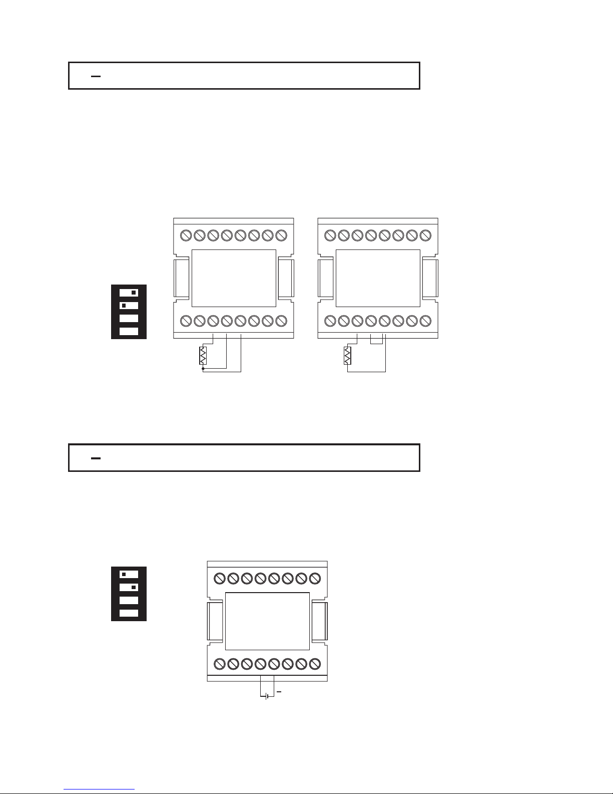
2 7 RTD Input Wiring2 7 RTD Input Wiring
2 8 Linear DC Input Wiring2 8 Linear DC Input Wiring
Figure 2.6
RTD Input Wiring
Figure 2.6
RTD
Input Wiring
DC linear voltage and linear current connections for input 1 are shown in Figure
2.7 and Figure 2.8 .
DC linear voltage and linear current connections for input 1 are shown in Figure
2.7
and Figure 2.8 .
DC linear voltage and linear current connections for input 2 are shown in Figure
2.9 and Figure 2.10 .
DC linear voltage and linear current connections for input 2 are shown in Figure
2.9
and Figure 2.10 .
Figure 2.7
Input 1 Linear Voltage Wiring
Figure 2.7
Input
1 Linear Voltage Wiring
1 2 3 4
ON
1 2 3 4
ON
DIP SwitchDIP Switch
DIP SwitchDIP Switch
Two-wire RTD should be avoided, if possible, for the purpose of accuracy. A 0.4
ohm lead resistance of a two-wire RTD will produce 1 degree C temperature
error.
Two-wire RTD should be avoided, if possible, for the purpose of accuracy. A 0.4
ohm lead resistance of a two-wire RTD will produce 1 degree C temperature
error.
192
10
3114
12
5
13
6147158
16
RTD
Three-wire RTDThree-wire RTD
192
10
3114
12
5
13
6147158
16
RTD
Two-wire RTDTwo-wire RTD
0~1V, 0~5V
1~5V, 0~10V
0~1V, 0~5V
1~5V,
0~10V
192
10
3114
12
5
13
6147158
16
26
UM93001C
RTD connection are shown in Figure 2.6, with the compensating lead connected to
terminal 12. For two-wire RTD inputs, terminals 12 and 13 should be linked. The
three-wire RTD offers the capability of lead resistance compensation provided that the
three leads should be of same gauge and equal length.
RTD connection are shown in Figure 2.6, with the compensating lead connected to
terminal
12. For two-wire RTD inputs, terminals 12 and 13 should be linked. The
three-wire
RTD offers the capability of lead resistance compensation provided that the
three
leads should be of same gauge and equal length.
+
Page 27

Figure 2.9
Input 2 Linear Voltage Wiring
Figure 2.9
Input
2 Linear Voltage Wiring
Figure 2.10
Input 2 Linear Current Wiring
Figure 2.10
Input
2 Linear Current Wiring
192
10
3114
12
5
13
6147158
16
0~1V, 0~5V
1~5V, 0~10V
0~1V, 0~5V
1~5V,
0~10V
192
10
3114
12
5
13
6147158
16
0~20mA or
4~20mA
0~20mA or
4~20mA
+
Figure 2.8
Input 1 Linear Current Wiring
Figure 2.8
Input
1 Linear Current Wiring
192
10
3114
12
5
13
6147158
16
0~20mA or
4~20mA
0~20mA or
4~20mA
1 2 3 4
ON
+
DIP SwitchDIP Switch
UM93001C
27
+
Page 28

2 9 CT / Heater Current Input Wiring2 9 CT / Heater Current Input Wiring
CT94 1
1
2
+
+
DIN RailDIN Rail
192
10
3114
12
5
13
6147158
16
Fuse
Mains
supply
Mains
supply
Heater 1Heater 1
Heater 2Heater 2
Heater 3Heater 3
Figure 2.11
CT Input Wiring for
Single Phase Heater
Figure 2.11
CT
Input Wiring for
Single
Phase Heater
Heater SupplyHeater Supply
Current TransformerCurrent Transformer
Contactor
CT Signal Input
CT Signal Input
CT94 1
1
2
+
DIN RailDIN Rail
Current TransformerCurrent Transformer
+
192
10
3114
12
5
13
6147158
16
Fuse
Mains
supply
Mains
supply
Figure 2.12
CT Input Wiring for
Three Phase Heater
Figure 2.12
CT
Input Wiring for
Three
Phase Heater
Contactor
CT Signal Input
CT Signal Input
Make sure that the total current through CT94-1 not exceed 50A rms.Make sure that the total current through CT94-1 not exceed 50A rms.
Three Phase
Heater Power
Three Phase
Heater
Power
28
UM93001C
Page 29
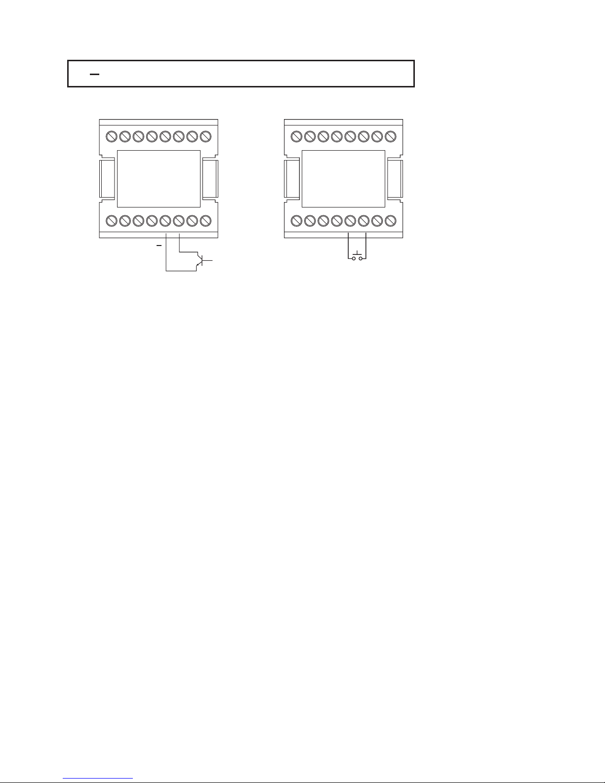
2 10 Event Input wiring2 10 Event Input wiring
Open Collector
Input
Open Collector
Input
Switch InputSwitch Input
+
192
10
3114
12
5
13
6147158
16
192
10
3114
12
5
13
6147158
16
Figure 2.13
Event Input Wiring
Figure 2.13
Event
Input Wiring
The event input can accept a switch signal as well as an open collector signal. The
event input function ( EIFN ) is activated as the switch is closed or an open collector (
or a logic signal ) is pulled down.
Also refer to for event input function.Section 4-1
The event input can accept a switch signal as well as an open collector signal. The
event
input function ( EIFN ) is activated as the switch is closed or an open collector (
or
a logic signal ) is pulled down.
Also
refer to for event input function.Section 4-1
UM93001C
29
Page 30

2 11 Output 1 Wiring2 11 Output 1 Wiring
192
10
3114
12
5
13
6147158
16
120V/240V
Mains Supply
120V/240V
Mains
Supply
Max. 2A
Resistive
Max. 2A
Resistive
Load
Relay Output Direct DriveRelay Output Direct Drive
Relay or Triac (SSR)
Output to Drive
Contactor
Relay or Tri a c (SSR)
Output
to Drive
Contactor
+
192
10
3114
12
5
13
6147158
16
Load
120V /240V
Mains Supply
120V /240V
Mains
Supply
+
_
SSR
30mA / 5V
Pulsed
Voltage
30mA / 5V
Pulsed
Voltage
Internal CircuitInternal Circuit
+
5V
0V
6
5
33
33
Pulsed Voltage to Drive SSRPulsed Voltage to Drive SSR
Figure 2.14
Output 1 Wiring
Figure 2.14
Output
1 Wiring
192
10
3114
12
5
13
6147158
16
120V /240V
Mains Supply
120V /240V
Mains
Supply
No Fuse
Breaker
No Fuse
Breaker
Three
Phase
Heater
Power
Three
Phase
Heater
Power
Three Phase
Delta
Heater
Load
Three Phase
Delta
Heater
Load
Contactor
30
UM93001C
Page 31

192
10
3114
12
5
13
6147158
16
0-1V, 0-5V
1-5V,0-10V
0 - 1V, 0 - 5V
1
- 5V, 0 - 10V
Linear VoltageLinear Voltage
192
10
3114
12
5
13
6147158
16
Linear CurrentLinear Current
Maximum Load 500 ohmsMaximum Load 500 ohms
Minimum Load 10 K ohmsMinimum Load 10 K ohms
192
10
3114
12
5
13
6147158
16
Max.1A/240VMax. 1A / 240V
Load
Tria c
Triac (SSR) Output
Direct Drive
Tri a c (SSR) Output
Direct
Drive
+
+
0-20mA,
4-20mA
0 - 20mA,
4
- 20mA
Load
+
+
Load
120V /240V
Mains Supply
120V /240V
Mains
Supply
UM93001C
31
Page 32
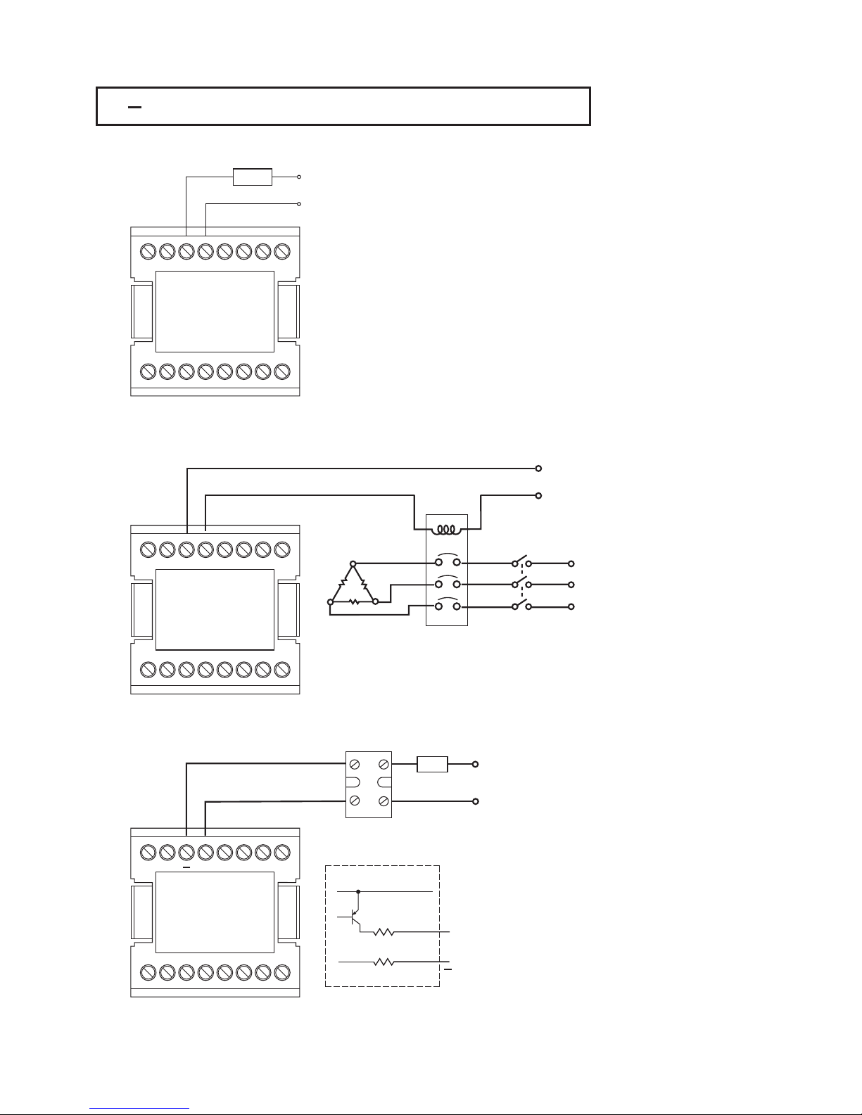
2 12 Output 2 Wiring2 12 Output 2 Wiring
192
10
3114
12
5
13
6147158
16
120V/240V
Mains Supply
120V/240V
Mains
Supply
Max. 2A
Resistive
Max. 2A
Resistive
Load
Relay Output Direct DriveRelay Output Direct Drive
Relay or Triac (SSR)
Output to Drive
Contactor
Relay or Tri a c (SSR)
Output
to Drive
Contactor
+
192
10
3114
12
5
13
6147158
16
Load
120V /240V
Mains Supply
120V /240V
Mains
Supply
+
_
SSR
30mA / 5V
Pulsed
Voltage
30mA / 5V
Pulsed
Voltage
Internal CircuitInternal Circuit
+
5V
0V
4
3
33
33
Pulsed Voltage to Drive SSRPulsed Voltage to Drive SSR
Figure 2.15
Output 2 Wiring
Figure 2.15
Output
2 Wiring
192
10
3114
12
5
13
6147158
16
120V /240V
Mains Supply
120V /240V
Mains
Supply
No Fuse
Breaker
No Fuse
Breaker
Three
Phase
Heater
Power
Three
Phase
Heater
Power
Three Phase
Delta
Heater
Load
Three Phase
Delta
Heater
Load
Contactor
32
UM93001C
Page 33

Linear VoltageLinear Voltage
Linear CurrentLinear Current
Maximum Load 500 ohmsMaximum Load 500 ohms
Minimum Load 10 K ohmsMinimum Load 10 K ohms
192
10
3114
12
5
13
6147158
16
Max.1A/240VMax. 1A / 240V
Load
Tria c
Triac (SSR) Output
Direct Drive
Tri a c (SSR) Output
Direct
Drive
192
10
3114
12
5
13
6147158
16
+
+
0-20mA,
4-20mA
0 - 20mA,
4
- 20mA
Load
192
10
3114
12
5
13
6147158
16
0-1V, 0-5V
1-5V,0-10V
0 - 1V, 0 - 5V
1
- 5V, 0 - 10V
+
+
Load
120V /240V
Mains Supply
120V /240V
Mains
Supply
UM93001C
33
Page 34
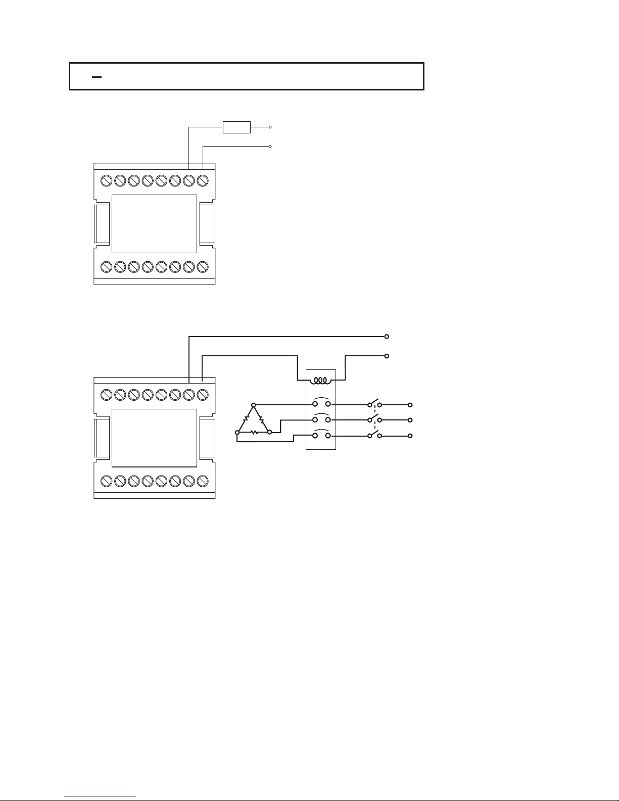
2 13 Alarm 1 Wiring2 13 Alarm 1 Wiring
192
10
3114
12
5
13
6147158
16
120V/240V
Mains Supply
120V/240V
Mains
Supply
Max. 2A
Resistive
Max. 2A
Resistive
Load
Relay Output Direct DriveRelay Output Direct Drive
Relay Output to
Drive Contactor
Relay Output to
Drive
Contactor
Figure 2.16
Alarm 1 Wiring
Figure 2.16
Alarm
1 Wiring
Note: Both Form A and B contacts are available for alarm 1 relay.
Order a correct form for alarm 1 to suit for your application.
Note: Both Form A and B contacts are available for alarm 1 relay.
Order
a correct form for alarm 1 to suit for your application.
192
10
3114
12
5
13
6147158
16
120V /240V
Mains Supply
120V /240V
Mains
Supply
No Fuse
Breaker
No Fuse
Breaker
Three
Phase
Heater
Power
Three
Phase
Heater
Power
Three Phase
Delta
Heater
Load
Three Phase
Delta
Heater
Load
Contactor
UM93001C
34
Page 35

2 14 Alarm 2 Wiring2 14 Alarm 2 Wiring
192
10
3114
12
5
13
6147158
16
120V/240V
Mains Supply
120V/240V
Mains
Supply
Max. 2A
Resistive
Max. 2A
Resistive
Load
Relay Output Direct DriveRelay Output Direct Drive
Figure 2.17
Alarm 2 Wiring
Figure 2.17
Alarm
2 Wiring
Relay Output to
Drive Contactor
Relay Output to
Drive
Contactor
192
10
3114
12
5
13
6147158
16
120V /240V
Mains Supply
120V /240V
Mains
Supply
No Fuse
Breaker
No Fuse
Breaker
Three
Phase
Heater
Power
Three
Phase
Heater
Power
Three Phase
Delta
Heater
Load
Three Phase
Delta
Heater
Load
Contactor
UM93001C
35
Page 36

2 15 RS-4852 15 RS-485
192
10
3114
12
5
13
6147158
16
192
10
3114
12
5
13
6147158
16
192
10
3114
12
5
13
6147158
16
TX1
TX1
TX1
TX1
TX2
TX2
TX2
TX2
Terminator
220 ohms / 0.5W
Terminator
220
ohms / 0.5W
Max. 247 units can be linkedMax. 247 units can be linked
RS-232
PC
SNA10A or
SNA10B
SNA10A or
SNA10B
Figure 2.18
RS-485 Wiring
Figure 2.18
RS-485
Wiring
RS-485 to RS-232
network adaptor
RS-485 to RS-232
network
adaptor
RS-485
UM93001C
Twisted-Pair WireTwisted-Pair Wire
36
Page 37

2 16 RS-2322 16 RS-232
192
10
3114
12
5
13
6147158
16
TX1 TX2
Note:
If the BTC-9300 is configured for RS-232 communication, the EI ( Event
Input ) is disconnected internally. The unit can no longer perform event
input function (EIFN).
If the BTC-9300 is configured for RS-232 communication, the EI ( Event
Input
) is disconnected internally. The unit can no longer perform event
input
function (EIFN).
COM
PC
9-pin
RS-232 port
9-pin
RS-232
port
Figure 2.19
RS-232 Wiring
Figure 2.19
RS-232
Wiring
UM93001C
CC94-1
37
T930-B
JA
7
1
JB
J2
J1
16
9
CN21
RY21M21
M22
1
8
JP21
CN22
JP22
When you insert a RS-232 module (CM94-2) to the connectors on CPU board
(C930), the jumper JP22 on terminal board (T930) be modified as following:
J1 must be shorted and J2 must be cut and left open. Location of JP22 is shown
in the following diagram.
must
When you insert a RS-232 module (CM94-2) to the connectors on CPU board
(C930),
the jumper JP22 on terminal board (T930) be modified as following:
J1
must be shorted and J2 must be cut and left open. Location of JP22 is shown
in
the following diagram.
must
If you use a conventional 9-pin RS-232 cable instead of CC94-1, the cable must
be modified according to the following circuit diagram.
If you use a conventional 9-pin RS-232 cable instead of CC94-1, the cable must
be
modified according to the following circuit diagram.
1
2
3
4
5
6
7
8
9
BTC-9300
TX1
TX1 RD
9
10
14
TX2
TX2 TD
COM
COM GND
Female DB-9Female DB-9
To DTE(PC) RS-232 PortTo DTE(PC) RS-232 Port
1 DCD
2RD
3TD
4 DTR
5 GND
6 DSR
7 RTS
8 CTS
9RI
1 DCD
2
RD
3
TD
4
DTR
5
GND
6
DSR
7
RTS
8
CTS
9
RI
Figure 2.21
Configuration of RS-232
Cable
Figure 2.21
Configuration
of RS-232
Cable
Figure 2.20
Location of Jumper JP22
Figure 2.20
Location
of Jumper JP22
Page 38

2 17 Analog Retransmission2 17 Analog Retransmission
192
10
3114
12
5
13
6147158
16
192
10
3114
12
5
13
6147158
16
+
+
+
+++
++
Load
Load
Load
Load
Load
Load
0-20mA,
4-20mA
0 - 20mA,
4
- 20mA
1-5V,0-5V
0 - 10V
1 - 5 V, 0 - 5V
0
- 10V
The total effective resistance of serial
loads can't exceed 500 ohms.
The total effective resistance of serial
loads
can't exceed 500 ohms.
Retransmit CurrentRetransmit Current
The total effective resistance of parallel
loads should be greater than 10K Ohms.
The total effective resistance of parallel
loads
should be greater than 10K Ohms.
Retransmit VoltageRetransmit Voltage
Figure 2.22 Analog
Retransmission Wiring
Figure 2.22 Analog
Retransmission
Wiring
Indicators
PLC's
Recorders
Data loggers
Inverters etc.
Indicators
PLC's
Recorders
Data
loggers
Inverters
etc.
Indicators
PLC's
Recorders
Data loggers
Inverters etc.
Indicators
PLC's
Recorders
Data
loggers
Inverters
etc.
UM93001C
38
Page 39

2 18 Programming Port2 18 Programming Port
See Figure 1.3 in Section 1-3 to find the programming port location.See Figure 1.3 in Section 1-3 to find the programming port location.
The programming port is used for off-line automatic setup and testing procedures only.
Don't attempt to make any connection to these jumpers when the unit is used for a
normal control purpose.
The programming port is used for off-line automatic setup and testing procedures only.
Don't
attempt to make any connection to these jumpers when the unit is used for a
normal
control purpose.
Switch Unit
DMM
Calibrator
SW6400
HP 34401A
HP 34401A
Fluke 5520AFluke 5520A
UM93001C
NOTE
39
Figure 2.23 Programming
Port Wiring
Figure 2.23 Programming
Port
Wiring
Programmer
connector and
ATE connector
inserted here
Programmer
connector
and
ATE
connector
inserted
here
Access hole
on the
bottom view
Access hole
on
the
bottom
view
INPT1
Programmer
P10A
Programmer
P10A
1
ON DIP
234
Page 40

This unit provides an useful parameter " FUNC " which can be used to select
the function complexity level before setup. If the Basic Mode ( FUNC = BASC )
is selected for a simple application, then the following functions are ignored
and deleted from the full function menu:
RAMP, SP2, PB2, TI2, TD2, PL1, PL2, COMM, PROT, ADDR, BAUD, DATA,
PARI, STOP, AOFN, AOLO, AOHI, IN2, IN2U, DP2, IN2L, IN2H, EIFN, PVMD,
FILT, SLEP, SPMD and SP2F.
This unit provides an useful parameter " FUNC " which can be used to select
the
function complexity level before setup. If the Basic Mode ( FUNC = BASC )
is
selected for a simple application, then the following functions are ignored
and
deleted from the full function menu:
RAMP,
SP2, PB2, TI2, TD2, PL1, PL2, COMM, PROT, ADDR, BAUD, DATA,
PARI,
STOP, AOFN, AOLO, AOHI, IN2, IN2U, DP2, IN2L, IN2H, EIFN, PVMD,
FILT,
SLEP, SPMD and SP2F.
(1) Second setpoint
(2) Second PID
(3) Event input
(4) Soft start (RAMP)
(5) Remote set point
(6) Complex process value
(7) Output power limit
(8) Digital communication
(9) Analog retransmission
(10) Power shut off (Sleep Mode)
(11) Digital filter
(12) Pump control
(13) Remote lockout
(1) Second setpoint
(2)
Second PID
(3)
Event input
(4)
Soft start (RAMP)
(5)
Remote set point
(6)
Complex process value
(7)
Output power limit
(8)
Digital communication
(9)
Analog retransmission
(10)
Power shut off (Sleep Mode)
(11)
Digital filter
(12)
Pump control
(13)
Remote lockout
(1) Input 1: Thermocouple, RTD, Volt, mA
(2) Input 2: CT for heater break detection
(3) Output 1: Heating or Cooling ( Relay, SSR, SSRD, Volt, mA )
(4) Output 2 : Cooling ( Relay, SSR, SSRD, Volt, mA ), DC Power supply.
(5) Alarm 1: Relay for Deviation, Deviation Band, Process, Heater Break, Loop
Break, Sensor Break, Latch, Hold or Normal Alarm.
(6) Alarm 2: Relay for Deviation, Deviation Band, Process, Heater Break, Loop
Break, Sensor Break, Latch, Hold or Normal Alarm.
(7) Dwell Timer
(8) Heater Break Alarm
(9) Loop Break Alarm
(10) Sensor Break Alarm
(11) Failure Transfer
(12) Bumpless Transfer
(13) PV1 Shift
(14) Programmable SP1 Range
(15) Heat-Cool control
(16) Hardware Lockout
(17) Self-Tune
(18) Auto-Tune
(19) ON-OFF, P, PD, PI, PID Control
(20) User Defined Menu (SEL)
(21) Manual Control
(22) Display Mode
(23) Reload Default Values
(24) Isolated DC Power Supply
(1) Input 1: Thermocouple, RTD, Volt, mA
(2)
Input 2: CT for heater break detection
(3)
Output 1: Heating or Cooling ( Relay, SSR, SSRD, Volt, mA )
(4)
Output 2 : Cooling ( Relay, SSR, SSRD, Volt, mA ), DC Power supply.
(5)
Alarm 1: Relay for Deviation, Deviation Band, Process, Heater Break, Loop
Break,
Sensor Break, Latch, Hold or Normal Alarm.
(6)
Alarm 2: Relay for Deviation, Deviation Band, Process, Heater Break, Loop
Break,
Sensor Break, Latch, Hold or Normal Alarm.
(7)
Dwell Timer
(8)
Heater Break Alarm
(9)
Loop Break
Alarm
(10)
Sensor Break Alarm
(11)
Failure Transfer
(12)
Bumpless Transfer
(13)
PV1 Shift
(14)
Programmable SP1 Range
(15)
Heat-Cool control
(16)
Hardware Lockout
(17)
Self-Tune
(18)
Auto-Tune
(19)
ON-OFF, P, PD, PI, PID Control
(20)
User Defined Menu (SEL)
(21)
Manual Control
(22)
Display Mode
(23)
Reload Default Values
(24)
Isolated DC Power Supply
Basic Mode capabilities:Basic Mode capabilities:
If you don't need:If you don't need:
then you can use Basic Mode.then you can use Basic Mode.
Chapter 3 Programming the Basic FunctionChapter 3 Programming the Basic Function
3 1 Input 13 1 Input 1
Press to enter Setup Mode. Press to select parameter. The upper
display indicates the parameter symbol, and the lower display indicates the
selection or the value of parameter.
Press to enter Setup Mode. Press to select parameter. The upper
display
indicates the parameter symbol, and the lower display indicates the
selection
or the value of parameter.
IN1 : Selects the sensor type and signal type for Input 1.IN1 : Selects the sensor type and signal type for Input 1.
Range:
Default :
( Thermocouple ) J_TC, K_TC, T_TC, E_TC, B_TC, R_ TC, S_TC,
N_TC, L_TC
( RTD ) PT.DN, PT.JS
(Linear ) 4-20, 0-20, 0-1V, 0-5V, 1-5V, 0-10
J_TC if F is selected, K_TC if C is selected.LL
Range:
Default
:
(
Thermocouple ) J_TC, K_TC, T_TC, E_TC, B_TC, R_ TC, S_TC,
N_TC,
L_TC
(
RTD ) PT.DN, PT.JS
(Linear
) 4-20, 0-20, 0-1V, 0-5V, 1-5V, 0-10
J_TC
if F is selected, K_TC if C is selected.LL
IN1U:
Range:
Default:
Selects the process unit for Input 1.
C, F, PU ( process unit ) If the unit is neither C nor F, then
selects PU.
Cor F.
LL L L
LL
IN1U:
Range:
Default:
Selects the process unit for Input 1.
C, F,
PU ( process unit ) If the unit is neither C nor F, then
selects
PU.
C
or F.
LL L L
LL
DP1 :
Range:
Default:
Selects the location of the decimal point for most ( not all ) process
related parameters.
( For T/C and RTD ) NO.DP, 1-DP
( For Linear ) NO.DP, 1-DP, 2-DP, 3-DP
1-DP
DP1 :
Range:
Default:
Selects the location of the decimal point for most ( not all ) process
related
parameters.
(
For T/C and RTD ) NO.DP, 1-DP
(
For Linear ) NO.DP, 1-DP, 2-DP, 3-DP
1-DP
IN1
IN1U
DP1
40
UM93001C
Page 41

IN1L
IN1H
IN1L : Selects the low scale value for the Linear type input 1.
T/C or RTD type is selected for IN1.Hidden if :
IN1L : Selects the low scale value for the Linear type input 1.
T/C
or RTD type is selected for IN1.Hidden if :
IN1H : Selects the high scale value for the Linear type input 1.
T/C or RTD type is selected for IN1.Hidden if :
IN1H : Selects the high scale value for the Linear type input 1.
T/C
or RTD type is selected for IN1.Hidden if :
How to use IN1L and IN1H :How to use IN1L and IN1H :
If4-20mAisselected for IN1,let SL specifies the input signal low ( ie. 4 mA ),
SH specifies the input signal high ( ie. 20 mA ), S specifies the current input
signal value, the conversion curve of the process value is shown as follows :
If 4 - 20 mA is selected for IN1,let SL specifies the input signal low ( ie. 4 mA ),
SH
specifies the input signal high ( ie. 20 mA ), S specifies the current input
signal
value, the conversion curve of the process value is shown as follows :
IN1H
process value
PV1
IN1L
SL SHS
input signal
Figure 3.1 Conversion Curve for
Linear Type Process Value
Figure 3.1 Conversion Curve for
Linear
Ty pe Process Value
Formula : PV1 = IN1L + ( IN1H IN1L )Formula : PV1 = IN1L + ( IN1H IN1L )
SSLS SL
SH SLSH SL
Example : A 4-20 mA current loop pressure transducer with range0-15kg/cm
is connected to input 1, then perform the following setup :
Example : A 4-20 mA current loop pressure transducer with range 0 - 15 kg/cm
is
connected to input 1, then perform the following setup :
2
IN1=4-20 IN1L = 0.0
IN1U = PU IN1H = 15.0
DP1 = 1-DP
Of course, you may select other value for DP1 to alter the resolution.
IN1 = 4 - 20 IN1L = 0.0
IN1U
= PU IN1H = 15.0
DP1
= 1-DP
Of
course, you may select other value for DP1 to alter the resolution.
3 2 OUT1&OUT2Types3 2 OUT1 & OUT2 Ty p es
O1TY : Selects the signal type for Output 1.
The selection should be consistent with the output 1 module installed.
The available output 1 signal types are :
RELY : Mechanical relay
SSRD : Pulsed voltage output to drive SSR
SSR : Isolated zero-switching solid state relay
4-20 :4-20mAlinear current output
0-20 :0-20mAlinear current output
0-1V :0-1Vlinear voltage output
0-5V :0-5Vlinear voltage output
1-5V :1-5Vlinear voltage output
0-10V:0-10Vlinear voltage output
O1TY : Selects the signal type for Output 1.
The
selection should be consistent with the output 1 module installed.
The
available output 1 signal types are :
RELY
: Mechanical relay
SSRD
: Pulsed voltage output to drive SSR
SSR
: Isolated zero-switching solid state relay
4
- 20 : 4 - 20 mA linear current output
0
- 20 : 0 - 20 mA linear current output
0
- 1 V : 0 - 1 V linear voltage output
0
- 5 V : 0 - 5 V linear voltage output
1
- 5 V : 1 - 5 V linear voltage output
0
- 10V : 0 - 10 V linear voltage output
O2TY : Selects the signal type for Output 2
The selection should be consistent with the output 2 module installed.
The available output 2 signal types are the same as for O1TY.
O2TY : Selects the signal type for Output 2
The
selection should be consistent with the output 2 module installed.
The
available output 2 signal types are the same as for O1TY.
The range for linear current or voltage may not be very accurate. For 0 % output,
the value for4-20mAmaybe3.8mAto4mA;while for 100 % output, the value
for4-20mAmaybe20mAto21mA.However, this deviation will not degrade
the control performance at all.
The range for linear current or voltage may not be very accurate. For 0 % output,
the
value for 4 - 20 mA may be 3.8 mA to 4 mA; while for 100 % output, the value
for
4 - 20 mA may be 20 mA to 21 mA. However, this deviation will not degrade
the
control performance at all.
O1TY
O2TY
UM93001C
41
Page 42

3 3 Rearrange User Menu3 3 Rearrange User Menu
The conventional controllers are designed with a fixed parameters' scrolling. If
you need a more friendly operation to suit your application, the manufacturer
will say " sorry " to you. The BTC-9300 has the flexibility for you to select those
parameters which are most significant to you and put these parameters in the
front of display sequence.
The conventional controllers are designed with a fixed parameters' scrolling. If
you
need a more friendly operation to suit your application, the manufacturer
will
say " sorry " to you. The BTC-9300 has the flexibility for you to select those
parameters
which are most significant to you and put these parameters in the
front
of display sequence.
SEL1
SEL2
SEL3
SEL4
SEL5
: Selects the most significant parameter for view and change.
: Selects the 2'nd significant parameter for view and change.
: Selects the 3'rd significant parameter for view and change.
: Selects the 4'th significant parameter for view and change.
: Selects the 5'th significant parameter for view and change.
NONE, TIME, A1.SP, A1.DV, A2.SP, A2.DV, RAMP, OFST,
REFC, SHIF, PB1, TI1, TD1, C.PB, DB, SP2, PB2, TI2, TD2
When using the up-down key to select the parameters, you may not obtain
all of the above parameters. The number of visible parameters is dependent
on the setup condition. The hidden parameters for the specific application are
also deleted from the SEL selection.
Range :
SEL1
SEL2
SEL3
SEL4
SEL5
:
Selects the most significant parameter for view and change.
:
Selects the 2'nd significant parameter for view and change.
:
Selects the 3'rd significant parameter for view and change.
:
Selects the 4'th significant parameter for view and change.
:
Selects the 5'th significant parameter for view and change.
NONE,
TIME, A1.SP, A1.DV, A2.SP, A2.DV, RAMP, OFST,
REFC,
SHIF, PB1, TI1, TD1, C.PB, DB, SP2, PB2, TI2, TD2
When
using the up-down key to select the parameters, you may not obtain
all
of the above parameters. The number of visible parameters is dependent
on
the setup condition. The hidden parameters for the specific application are
also
deleted from the SEL selection.
Range :
SEL1
SEL2
SEL3
SEL4
SEL5
Example :
Example :
A1FN selects TIMR
A2FN selects DE.HI
PB1=10
TI1 = 0
SEL1 selects TIME
SEL2 selects A2.DV
SEL3 selects OFST
SEL4 selects PB1
SEL5 selects NONE
Now, the upper display scrolling becomes :
A1FN selects TIMR
A2FN
selects DE.HI
PB1
= 10
TI1
= 0
SEL1
selects TIME
SEL2
selects A2.DV
SEL3
selects OFST
SEL4
selects PB1
SEL5
selects NONE
Now,
the upper display scrolling becomes :
PV
42
UM93001D
Page 43

3 4 Heat Only Control3 4 Heat Only Control
Heat Only ON-OFF Control : Select REVR for OUT1, Set PB1 to 0, SP1 is used
to adjust set point value, O1HY is used to adjust dead band for ON-OFF
control, TIME is used to adjust the dwell timer ( enabled by selecting TIMR for
A1FN or A2FN ). The output 1 hysteresis ( O1HY ) is enabled in case of PB1 =
0 . The heat only on-off control function is shown in the following diagram :
Heat Only ON-OFF Control : Select REVR for OUT1, Set PB1 to 0, SP1 is used
to
adjust set point value, O1HY is used to adjust dead band for ON-OFF
control,
TIME is used to adjust the dwell timer ( enabled by selecting TIMR for
A1FN
or A2FN ). The output 1 hysteresis ( O1HY ) is enabled in case of PB1 =
0
. The heat only on-off control function is shown in the following diagram :
SP1+O1HY/2
SP1 O1HY/2
SP1
ON
OFF
OUT1 Action
PV
Dead band = O1HY
Time
Time
The ON-OFF control may introduce excessive process oscillation even if
hysteresis is minimized to the smallest. If ON-OFF control is set ( ie. PB1=0),
TI1, TD1, CYC1, OFST, CPB and PL1 will be hidden and have no function to the
system. The manual mode, auto-tuning, self-tuning and bumpless transfer will
be disabled too.
Select REVR for OUT1, set TI1 to 0, SP1 is used
to adjust set point value, TIME is used to adjust the dwell timer ( enabled by
selecting TIMR for A1FN or A2FN ). OFST been enabled in case of TI1 = 0
is used to adjust the control offset ( manual reset ). Adjust CYC1 according to
the output 1 type ( O1TY ).Generally, CYC1= 0.5 ~ 2 sec for SSRD and SSR,
CYC1=10 ~ 20 sec for relay output .CYC1 is ignored if linear output is selected
for O1TY. if PB1 is not equal to 0.
OFST is measured by % with range 0 - 100.0 %. In the steady
state ( ie. process has been stabilized ) if the process value is lower than the
set point a definite value, say 5 C, while 20 C is used for PB1, that is lower 25
%, then increase OFST 25 %, and vice versa. After adjusting OFST value, the
process value will be varied and eventually, coincide with set point.
Using the P control ( TI1 set to 0 ), the auto-tuning and self-tuning are disabled.
Refer to section 3-20 " manual tuning " for the adjustment of PB1 and TD1.
Manual reset ( adjust OFST ) is not practical because the load may change
from time to time and often need to adjust OFST repeatedly. The PID control
can avoid this situation.
Selecting REVR for OUT1, SP1 is used to adjust set
point value. TIME is used to adjust the dwell timer ( enabled by selecting
TIMR for A1FN or A2FN ). PB1 and TI1 should not be zero. Adjust CYC1
according to the output 1 type ( O1TY ). Generally, CYC1 = 0.5 ~ 2 sec for
SSRD and SSR, CYC1 = 10 ~ 20 sec for relay output. CYC1 is ignored if
linear output is selected for O1TY.
In most cases the self-tuning can be used to substitute the auto-tuning. See
If self-tuning is not used ( select NONE for SELF ), then use
auto-tuning for the new process, or set PB1, TI1 and TD1 with historical values.
See for auto-tuning operation. If the control result is still
unsatisfactory, then use manual tuning to improve the control . See
for manual tuning. BTC-9300 contains a
algorithm to achieve a to the
process if it is properly tuned.
Heat onlyP(orPD)control :
O1HY is hidden
OFST Function :
Heat only PID control :
Section 3-18.
Section 3-19
Section
3-20 very clever PID and Fuzzy
very small overshoot and very quick response
The ON-OFF control may introduce excessive process oscillation even if
hysteresis
is minimized to the smallest. If ON-OFF control is set ( ie. PB1 = 0 ),
TI1,
TD1, CYC1, OFST, CPB and PL1 will be hidden and have no function to the
system.
The manual mode, auto-tuning, self-tuning and bumpless transfer will
be
disabled too.
Select
REVR for OUT1, set TI1 to 0, SP1 is used
to
adjust set point value, TIME is used to adjust the dwell timer ( enabled by
selecting
TIMR for A1FN or A2FN ). OFST been enabled in case of TI1 = 0
is
used to adjust the control offset ( manual reset ). Adjust CYC1 according to
the
output 1 type ( O1TY ).Generally, CYC1= 0.5 ~ 2 sec for SSRD and SSR,
CYC1=10
~ 20 sec for relay output .CYC1 is ignored if linear output is selected
for
O1TY. if PB1 is not equal to 0.
OFST
is measured by % with range 0 - 100.0 %. In the steady
state
( ie. process has been stabilized ) if the process value is lower than the
set
point a definite value, say 5 C, while 20 C is used for PB1, that is lower 25
%,
then increase OFST 25 %, and vice versa. After adjusting OFST value, the
process
value will be varied and eventually, coincide with set point.
Using
the P control ( TI1 set to 0 ), the auto-tuning and self-tuning are disabled.
Refer
to section 3-20 " manual tuning " for the adjustment of PB1 and TD1.
Manual
reset ( adjust OFST ) is not practical because the load may change
from
time to time and often need to adjust OFST repeatedly. The PID control
can
avoid this situation.
Selecting
REVR for OUT1, SP1 is used to adjust set
point
value. TIME is used to adjust the dwell timer ( enabled by selecting
TIMR
for A1FN or A2FN ). PB1 and TI1 should not be zero. Adjust CYC1
according
to the output 1 type ( O1TY ). Generally, CYC1 = 0.5 ~ 2 sec for
SSRD
and SSR, CYC1 = 10 ~ 20 sec for relay output. CYC1 is ignored if
linear
output is selected for O1TY.
In
most cases the self-tuning can be used to substitute the auto-tuning. See
If
self-tuning is not used ( select NONE for SELF ), then use
auto-tuning
for the new process, or set PB1, TI1 and TD1 with historical values.
See for
auto-tuning operation. If the control result is still
unsatisfactory,
then use manual tuning to improve the control . See
for
manual tuning. BTC-9300 contains a
algorithm
to achieve atothe
process
if it is properly tuned.
Heat
only P ( or PD ) control :
O1HY
is hidden
OFST
Function :
Heat
only PID control :
Section
3-18.
Section
3-19
Section
3-20 very
clever PID and Fuzzy
very
small overshoot and very quick response
Figure 3.2 Heat Only
ON-OFF Control
Figure 3.2 Heat Only
ON-OFF
Control
Setup ON-OFF :
Adjust :
OUT1 =
PB1=0
SP1, O1HY, TIME( if enabled)
Setup ON-OFF :
Adjust
:
OUT1
=
PB1
= 0
SP1,
O1HY, TIME( if enabled)
Setup P:
OUT1 =
TI1=0
CYC1 ( if RELAY, SSRD or SSR is
selected for O1TY )
Setup P:
OUT1
=
TI1
= 0
CYC1
( if RELAY, SSRD or SSR is
selected
for O1TY )
Adjust :
SP1, OFST, TIME ( if enabled ),
PB1(=0),TD1
Adjust :
SP1,
OFST, TIME ( if enabled ),
PB1
( = 0 ), TD1
Setup PID :
Adjust:
OUT1 =
O1TY
CYC1 ( if RELAY, SSRD or SSR is
selected for O1TY )
SELF = NONE or YES
SP1, TIME ( if enabled ), PB1(=0),
TI1(=0),Td1.
Setup PID :
Adjust:
OUT1
=
O1TY
CYC1
( if RELAY, SSRD or SSR is
selected
for O1TY )
SELF
= NONE or YES
SP1,
TIME ( if enabled ), PB1 ( = 0 ),
TI1
( = 0 ), Td1.
Auto-tuning:
Used for new process. during initial
tuning
Auto-tuning:
Used
for new process. during initial
tuning
Self-tuning:
Used for a process any time.
Self-tuning:
Used
for a process any time.
Manual Tuning:
May be used if self-tuning and
auto-tuning are inadequate.
Manual Tuning:
May
be used if self-tuning and
auto-tuning
are inadequate.
UM93001C
43
Page 44

3 5 Cool Only Control3 5 Cool Only Control
ON-OFF control,P(PD)control and PID control can be used for cool control.
Set OUT1 to DIRT ( direct action ). The other functions for
control, control and control are same as
descriptions in section 3-4 for heat only control except that the output variable
( and action ) for the cool control is inverse to the heat control, such as the
following diagram shows:
cool only ON-OFF
cool onlyP(PD) cool only PID
ON-OFF control, P ( PD ) control and PID control can be used for cool control.
Set
OUT1 to DIRT ( direct action ). The other functions for
control, control
and control are same as
descriptions
in section 3-4 for heat only control except that the output variable
(
and action ) for the cool control is inverse to the heat control, such as the
following
diagram shows:
cool
only ON-OFF
cool
only P ( PD ) cool only PID
SP1+O1HY/2
SP1 O1HY/2
SP1
ON
OFF
OUT1 Action
PV
Dead band = O1HY
Time
Time
Figure 3.3 Cool Only
ON-OFF Control
Figure 3.3 Cool Only
ON-OFF
Control
Setup Cool Control :
OUT1 =
Setup Cool Control :
OUT1
=
Refer to section 3-4 in which similar descriptions for heat only control can be
applied to cool only control.
Refer to section 3-4 in which similar descriptions for heat only control can be
applied
to cool only control.
44
UM93001C
Page 45

3 6 Heat-Cool Control3 6 Heat-Cool Control
The Heat-Cool Control can use one of combinations of control modes. Setup of parameters for each control
mode are shown in the following table.
6The Heat-Cool Control can use one of combinations of control modes. Setup of parameters for each control
mode
are shown in the following table.
6
Control Modes
Heat
Uses
Cool
Uses
Setup Values
OUT1 OUT2 O1HY OFST
PB1 TI1 TD1
CPB
A2FN A2MD A2HY
Heat : ON-OFF
Cool : ON-OFF
Heat : ON-OFF
Cool:P(PD)
Heat : ON-OFF
Cool : PID
Heat:P(PD)
Cool : ON-OFF
Heat : PID
Cool : ON-OFF
Heat : PID
Cool : PID
OUT1
OUT2
OUT2
OUT1
OUT1
OUT1
OUT2
OUT1
OUT1
OUT2
OUT2
OUT2
REVR
DIRT
DIRT
REVR
REVR
REVR
=AL2
=AL2
=AL2
=AL2
=AL2
COOL
=0
DE.HI
or
PV1.H
DE.LO
or
PV1.L
DE.LO
or
PV1.L
DE.HI
or
PV1.H
DE.HI
or
PV1.H
NORM
NORM
NORM
NORM
NORM
=0
=0
=0
=0
=0
=0
=0
=0
=0
=0
: Don't care: Don't care
: Adjust to meet process
requirements
: Adjust to meet process
requirements
Table 3.1 Heat-Cool Control SetupTable 3.1 Heat-Cool Control Setup
NOTE :
Other Setup Required :
The ON-OFF control may result excessive overshoot and undershoot problems in the process. TheP(orPD)
control will result in a deviation process value from the set point. It is recommended to use PID control for the Heat-Cool
control to produce a stable and zero offset process value.
O1TY, CYC1, O2TY, CYC2, A2SP, A2DV
O1TY & O2TY are set in accordance with the types of OUT1 & OUT2 installed. CYC1 & CYC2 are selected according to
the output 1 type ( O1TY ) & output 2 type ( O2TY ).
Generally, selects 0.5 ~ 2 sec. for CYC1, if SSRD or SSR is used for O1TY; 10 ~ 20 sec. if relay is used for O1TY, and
CYC1 is ignored if linear output is used. Similar condition is applied for CYC2 selection.
If OUT2 is configured for ON-OFF control ( by selecting = AL2 ), the OUT2 acts as alarm output, and the process alarm
as well as deviation alarm ( see section 3-8 & 3-9 ) can be used. Adjust A2SP to change set point if process alarm is
used, and adjust SP1 ( with preset A2DV ) to change set point if deviation alarm is used.
NOTE :
Other
Setup Required :
The
ON-OFF control may result excessive overshoot and undershoot problems in the process. The P ( or PD )
control
will result in a deviation process value from the set point. It is recommended to use PID control for the Heat-Cool
control
to produce a stable and zero offset process value.
O1TY,
CYC1, O2TY, CYC2, A2SP, A2DV
O1TY
& O2TY are set in accordance with the types of OUT1 & OUT2 installed. CYC1 & CYC2 are selected according to
the
output 1 type ( O1TY ) & output 2 type ( O2TY ).
Generally,
selects 0.5 ~ 2 sec. for CYC1, if SSRD or SSR is used for O1TY; 10 ~ 20 sec. if relay is used for O1TY, and
CYC1
is ignored if linear output is used. Similar condition is applied for CYC2 selection.
If
OUT2 is configured for ON-OFF control ( by selecting = AL2 ), the OUT2 acts as alarm output, and the process alarm
as
well as deviation alarm ( see section 3-8 & 3-9 ) can be used. Adjust A2SP to change set point if process alarm is
used,
and adjust SP1 ( with preset A2DV ) to change set point if deviation alarm is used.
Examples:
Heat PID+Cool ON-OFF :
Heat PID+Cool PID :
self-tuning
auto-tuning
manual tuning
Set OUT1= REVR, OUT2= =AL2, A2FN= PV1.H, A2MD=NORM, A2HY=0.1, PB1=0,
TI1=0,TD1=0, and set appropriate values for O1TY and CYC1.
set OUT1=REVR, OUT2=COOL, CPB=100, DB=-4.0, PB1=0, TI1=0 TD1=0, and set appropriate value
s
for O1TY, CYC1, O2TY, CYC2.
If you have no idea about a new process, then use program to optimize the PID values by selecting YES for
SELF to enable the self-tuning program .See for self-tuning description. You can use the
program for the new process or directly set the appropriate values for PB1, TI1 & TD1 according to the historical records
for the repeated systems. If the control behavior is still inadequate, then use to improve the control. See
for manual tuning.
Section 3-18
Section 3-20
Examples:
Heat
PID+Cool ON-OFF :
Heat
PID+Cool PID :
self-tuning
auto-tuning
manual
tuning
Set
OUT1= REVR, OUT2= =AL2, A2FN= PV1.H, A2MD=NORM, A2HY=0.1, PB1=0,
TI1=0,TD1=0,
and set appropriate values for O1TY and CYC1.
set
OUT1=REVR, OUT2=COOL, CPB=100, DB=-4.0, PB1=0, TI1=0 TD1=0, and set appropriate values
for
O1TY, CYC1, O2TY, CYC2.
If
you have no idea about a new process, then use program to optimize the PID values by selecting YES for
SELF
to enable the self-tuning program .See for self-tuning description. You can use the
program
for the new process or directly set the appropriate values for PB1, TI1 & TD1 according to the historical records
for
the repeated systems. If the control behavior is still inadequate, then use to improve the control. See
for
manual tuning.
Section
3-18
Section
3-20
UM93001D
45
DB
Page 46

46
UM93001D
CPB Programming : The cooling proportional band is measured by % of PB with range 1~255. Initially set 100% for
CPB and examine the cooling effect. If cooling action should be enhanced then , if cooling action is
too strong then . The value of CPB is related to PB and its value remains unchanged throughout the
self-tuning and auto-tuning procedures.
decrease CPB
increase CPB
CPB Programming : The cooling proportional band is measured by % of PB with range 1~255. Initially set 100% for
CPB
and examine the cooling effect. If cooling action should be enhanced then , if cooling action is
too
strong then . The value of CPB is related to PB and its value remains unchanged throughout the
self-tuning
and auto-tuning procedures.
decrease
CPB
increase
CPB
Adjustment of CPB is related to the cooling media used. For air is used as cooling media, adjust CPB at 100(%).
For oil is used as cooling media, adjust CPB at 125(%). For water is used as cooling media, adjust CPB at 250(%).
DB Programming: Adjustment of DB is dependent on the system requirements. If more positive value of DB (
greater dead band ) is used, an unwanted cooling action can be avoided but an excessive overshoot over the set
point will occur. If more negative value of DB ( greater overlap ) is used, an excessive overshoot over the set point
can be minimized but an unwanted cooling action will occur. It is adjustable in the range -36.0% to 36.0 % of PB1 (
or PB2 if PB2 is selected ). A negative DB value shows an overlap area over which both outputs are active. A
positive DB value shows a dead band area over which neither output is active.
DB Programming:
Page 47
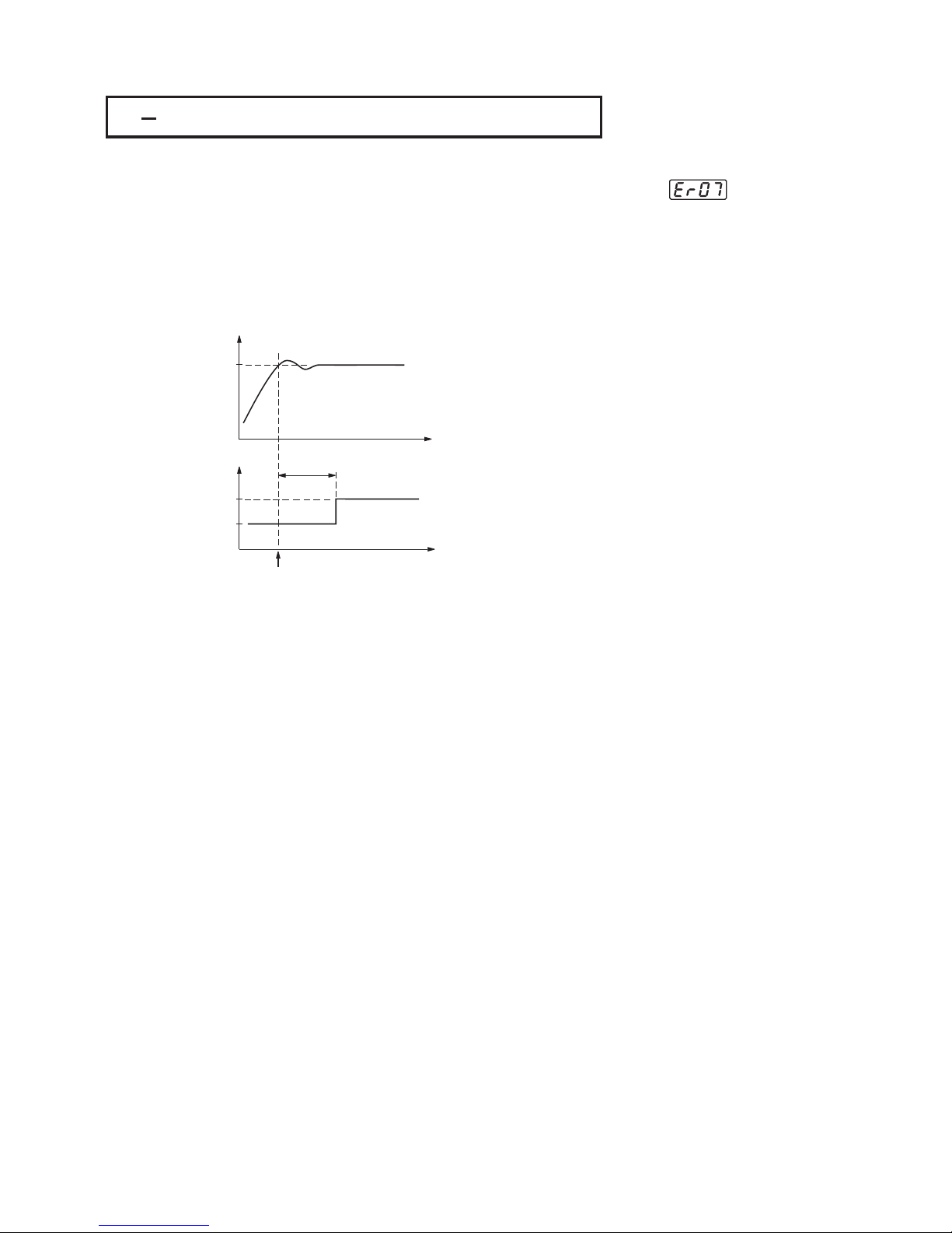
3 7 Dwell Timer3 7 Dwell Timer
SP1
PV
Time
ON
OFF
A1 or A2
Time
Time
TIME
Timer starts
Figure 3.4 Dwell Timer FunctionFigure 3.4 Dwell Timer Function
If alarm 1 is configured as dwell timer, A1SP, A1DV, A1HY and A1MD are hidden.
Same case is for alarm 2.
If alarm 1 is configured as dwell timer, A1SP, A1DV, A1HY and A1MD are hidden.
Same
case is for alarm 2.
Set A1FN=TIMR or A2FN=TIMR but not both.
Adjust TIME in minutes
A1MD ( if A1FN=TIMR ) or A2MD ( if A2FN=TIMR ) is ignored in this case.
If a form B relay is required for dwell timer, then order form B alarm 1 and
configure A1FN. Form B relay is not available for alarm 2.
Set A1FN=TIMR or A2FN=TIMR but not both.
Adjust
TIME in minutes
A1MD
( if A1FN=TIMR ) or A2MD ( if A2FN=TIMR ) is ignored in this case.
If
a form B relay is required for dwell timer, then order form B alarm 1 and
configure
A1FN. Form B relay is not available for alarm 2.
Example :Example :
UM93001C
47
Error CodeError Code
Alarm 1 or alarm 2 can be configured as dwell timer by selecting TIMR for
A1FN or A2FN, but not both, otherwise will appear. As the dwell timer is
configured, the parameter TIME is used for dwell time adjustment.
The dwell time is measured in minute ranging from 0 to 6553.5 minutes. Once
the process reaches the set point the dwell timer starts to count from zero until
time out.The timer relay will remain unchanged until time out. The dwell timer
operation is shown as following diagram.
Er07
Alarm 1 or alarm 2 can be configured as dwell timer by selecting TIMR for
A1FN or A2FN, but not both, otherwise will appear. As the dwell timer is
configured, the parameter TIME is used for dwell time adjustment.
The dwell time is measured in minute ranging from 0 to 6553.5 minutes. Once
the process reaches the set point the dwell timer starts to count from zero until
time out.The timer relay will remain unchanged until time out. The dwell timer
operation is shown as following diagram.
Er07
Page 48

3 8 Process Alarms3 8 Process Alarms
There are at most two independent alarms available by adjusting OUT2. If
=AL2 is selected for OUT2, then OUT2 will perform alarm 2 function. Now
A2FN can't be selected with NONE, otherwise will be displayed.
A process alarm sets an absolute trigger level ( or temperature ). When the
process ( could be PV1, PV 2 or PV1-PV2 ) exceeds that absolute trigger level
an alarm occurs. A process alarm is independent from set point.
Adjust A1FN ( Alarm 1 function ) in setup menu. One of 8 functions can be
selected for process alarm. These are : PV1.H, PV1.L, PV2.H, PV2.L, P1.2.H,
P1.2.L, D1.2.H, D1.2.L. When the PV1.H or PV1.L is selected the alarm
examines the PV1 value. When the PV2.H or PV2.L is selected the alarm
examines the PV2 value. When the P1.2.H or P1.2.L is selected the alarm
occurs if the PV1 or PV2 value exceed the trigger level. When the D1.2.H or
D1.2.L is selected the alarm occurs if the PV1-PV2 ( difference ) value exceeds
the trigger level. The trigger level is determined by A1SP ( Alarm 1 set point )
and A1HY ( Alarm 1 hysteresis value ) in User Menu for alarm 1. The hysteresis
value is introduced to avoid interference action of alarm in a noisy environment.
Normally A1HY can be set with a minimum ( 0.1 ) value.
A1DV and/or A2DV are hidden if alarm 1 and/or alarm 2 are set with process
alarm.
When a normal alarm is selected, the alarm output is de-energized in the
non-alarm condition and energized in an alarm condition.
If a latching alarm is selected, once the alarm output is energized, it will
remain unchanged even if the alarm condition is cleared. The latching alarms
are disabled when the power is shut off or if event input is applied with proper
selection of EIFN.
A holding alarm prevents an alarm from power up. The alarm is enabled
only when the process reaches the set point value ( may be SP1 or SP2,
See event input ). Afterwards, the alarm performs same
function as normal alarm.
Er06
Normal Alarm : A1MD = NORM
Latching Alarm : A1MD = LTCH
Holding Alarm : A1MD = HOLD
Section 4-1
There are at most two independent alarms available by adjusting OUT2. If
=AL2
is selected for OUT2, then OUT2 will perform alarm 2 function. Now
A2FN
can't be selected with NONE, otherwise will be displayed.
A
process alarm sets an absolute trigger level ( or temperature ). When the
process
( could be PV1, PV 2 or PV1-PV2 ) exceeds that absolute trigger level
an
alarm occurs. A process alarm is independent from set point.
Adjust
A1FN ( Alarm 1 function ) in setup menu. One of 8 functions can be
selected
for process alarm. These are : PV1.H, PV1.L, PV2.H, PV2.L, P1.2.H,
P1.2.L,
D1.2.H, D1.2.L. When the PV1.H or PV1.L is selected the alarm
examines
the PV1 value. When the PV2.H or PV2.L is selected the alarm
examines
the PV2 value. When the P1.2.H or P1.2.L is selected the alarm
occurs
if the PV1 or PV2 value exceed the trigger level. When the D1.2.H or
D1.2.L
is selected the alarm occurs if the PV1-PV2 ( difference ) value exceeds
the
trigger level. The trigger level is determined by A1SP ( Alarm 1 set point )
and
A1HY ( Alarm 1 hysteresis value ) in User Menu for alarm 1. The hysteresis
value
is introduced to avoid interference action of alarm in a noisy environment.
Normally
A1HY can be set with a minimum ( 0.1 ) value.
A1DV
and/or A2DV are hidden if alarm 1 and/or alarm 2 are set with process
alarm.
When
a normal alarm is selected, the alarm output is de-energized in the
non-alarm
condition and energized in an alarm condition.
If
a latching alarm is selected, once the alarm output is energized, it will
remain
unchanged even if the alarm condition is cleared. The latching alarms
are
disabled when the power is shut off or if event input is applied with proper
selection
of EIFN.
A
holding alarm prevents an alarm from power up. The alarm is enabled
only
when the process reaches the set point value ( may be SP1 or SP2,
See event
input ). Afterwards, the alarm performs same
function
as normal alarm.
Er06
Normal Alarm : A1MD = NORM
Latching
Alarm : A1MD = LTC H
Holding
Alarm : A1MD = HOLD
Section 4-1
Process Alarm 1Process Alarm 1
Setup : A1FN, A1MDSetup : A1FN, A1MD
Adjust : A1SP, A1HYAdjust : A1SP, A1HY
Process Alarm 2Process Alarm 2
Setup : OUT2, A2FN, A2MDSetup : OUT2, A2FN, A2MD
Adjust : A2SP, A2HYAdjust : A2SP, A2HY
Trigger level = A1SP 1/2 A1HYATrigger level = A1SP 1/2 A1HYA
Trigger level = A2SP 1/2 A2HYATrigger level = A2SP 1/2 A2HYA
Reset Latching alarmReset Latching alarm
1. Power off1. Power off
2. Apply Event input in accordance2. Apply Event input in accordance
with proper selection of EIFNwith proper selection of EIFN
205
195
205
195
205 205 205
195 195 195
ON
OFF
Figure 3.5
Normal Process Alarm
Figure 3.5
Normal
Process Alarm
A1SP = 200 A1HY = 10.0
A1MD = NORM A1FN = PV1.H
A1SP = 200 A1HY = 10.0
A1MD
= NORM A1FN = PV1.H
Process proceedsProcess proceeds
Examples:
Latching / Holding Alarm : A1MD = LT.HO
A latching / holding alarm performs both holding and latching function.
Latching / Holding Alarm : A1MD = LT.HO
A latching / holding alarm performs both holding and latching function.
8 Types of Process Alarms :
PV1.H, PV1.L, PV2.H, PV2.L, P1.2.H,
P1.2.L, D1.2.H, D1.2.L
8 Types of Process Alarms :
PV1.H,
PV1.L, PV2.H, PV2.L, P1.2.H,
P1.2.L,
D1.2.H, D1.2.L
48
UM93001C
Error CodeError Code
Page 49

205
195
205
195
205
205
205
195
195
195
ON
Figure 3.6
Latching Process Alarm
Figure 3.6
Latching
Process Alarm
A1SP = 200 A1HY = 10.0
A1MD = LTCH A1FN = PV1.H
A1SP = 200 A1HY = 10.0
A1MD
= LTC H A1FN = PV1.H
Process proceedsProcess proceeds
Although the above descriptions are based on alarm 1, the same conditions can
be applied to alarm 2.
Although the above descriptions are based on alarm 1, the same conditions can
be
applied to alarm 2.
205
205
195
195
205
205
195
195
205
205
210
210
210
210
210
210 210
210
205
205
205
205 205
205
195
195
195
195
195
195 195
195
ON
OFF
ON
Figure 3.7
Holding Process Alarm
Figure 3.7
Holding
Process Alarm
Figure 3.8
Latching / Holding
Process Alarm
Figure 3.8
Latching
/ Holding
Process
Alarm
A1SP = 200 A1HY = 10.0 SP1 = 210
A1MD = HOLD A1FN = PV1.L
A1SP = 200 A1HY = 10.0 SP1 = 210
A1MD
= HOLD A1FN = PV1.L
A1SP = 200 A1HY = 10.0 SP1 = 210
A1MD = LT.HO A1FN = PV1.L
A1SP = 200 A1HY = 10.0 SP1 = 210
A1MD
= LT.HO A1FN = PV1.L
Process proceedsProcess proceeds
Process proceedsProcess proceeds
( 3-8 2'nd page )( 3-8 2'nd page )
UM93001C
49
Page 50

3 9 Deviation Alarm3 9 Deviation Alarm
A1FN = DE.HI, A1MD = NORM, SP1 = 100, A1DV=10, A1HY=4A1FN = DE.HI, A1MD = NORM, SP1 = 100, A1DV=10, A1HY=4
A1FN = DE.HI, A1MD = LTCH, SP1 = 100, A1DV=10, A1HY=4A1FN = DE.HI, A1MD = LTCH, SP1 = 100, A1DV=10, A1HY=4
A1HY = DE.LO, A1MD = HOLD, SP1 = 100, A1DV= -10, A1HY=4A1HY = DE.LO, A1MD = HOLD, SP1 = 100, A1DV= -10, A1HY=4
112
112
100
100
100
100
100
100
100
112
112
112
112
112
112
112
112
108
108
92
92
92
92
92
92
92
108
108
108
108
108
108
108
108
100
100
88
88
88
88
88
88
88
100
100
100
100
100
100
100
100
ON
ON
ON
OFF
OFF
Process proceedsProcess proceeds
Process proceedsProcess proceeds
Process proceedsProcess proceeds
Process proceedsProcess proceeds
Examples:
Figure 3.9
Normal Deviation Alarm
Figure 3.9
Normal
Deviation Alarm
Figure 3.10
Latching Deviation Alarm
Figure 3.10
Latching
Deviation Alarm
Figure 3.11 Holding
Deviation Alarm
Figure 3.11 Holding
Deviation
Alarm
2 Types of Deviation Alarms :
DE.HI, DE.LO
2 Types of Deviation Alarms :
DE.HI,
DE.LO
Deviation Alarm 1
Setup : A1FN, A1MD
Adjust : SP1, A1DV, A1HY
Trigger levels=SP1+A1DV 1/2A1HYA
Deviation Alarm 1
Setup
: A1FN, A1MD
Adjust
: SP1, A1DV, A1HY
Trigger
levels=SP1+A1DV 1/2A1HYA
Deviation Alarm 2 :
Setup : OUT2, A2FN, A2MD
Adjust : SP1, A2DV, A2HY
Trigger levels=SP1+A2DV /2A2HYA
Deviation Alarm 2 :
Setup
: OUT2, A2FN, A2MD
Adjust
: SP1, A2DV, A2HY
Trigger
levels=SP1+A2DV /2A2HYA
OUT2 can be configured as alarm 2 by selecting=AL2. If OUT2 selects=AL2,
then output 2 will perform alarm 2 function. Now A2FN can't be selected with
NONE, otherwise will appear.
A deviation alarm alerts the user when the process deviates too far from set
point. The user can enter a positive or negative deviation value ( A1DV, A2DV )
for alarm 1 and alarm 2. A hysteresis value ( A1HY or A2HY ) can be selected to
avoid interference problem of alarm in a noisy environment. Normally, A1HY
and A2HY can be set with a minimum ( 0.1 ) value.
Trigger levels of alarm are moving with set point.
For alarm 1, Trigger levels=SP1+A1DV 1/2 A1HY.
For alarm 2, Trigger levels=SP1+A2DV 1/2 A2HY.
A1SP and/or A2SP are hidden if alarm 1 and/or alarm 2 are set with deviation
alarm. One of 4 kinds of alarm modes can be selected for alarm 1 and alarm 2.
These are: Normal alarm, Latching alarm, Holding alarm and Latching/Holding
alarm. See for descriptions of these alarm modes.
Er06
Section 3-8
A
A
OUT2 can be configured as alarm 2 by selecting=AL2. If OUT2 selects=AL2,
then
output 2 will perform alarm 2 function. Now A2FN can't be selected with
NONE,
otherwise will appear.
A
deviation alarm alerts the user when the process deviates too far from set
point.
The user can enter a positive or negative deviation value ( A1DV, A2DV )
for
alarm 1 and alarm 2. A hysteresis value ( A1HY or A2HY ) can be selected to
avoid
interference problem of alarm in a noisy environment. Normally, A1HY
and
A2HY can be set with a minimum ( 0.1 ) value.
Trigger
levels of alarm are moving with set point.
For
alarm 1, Trigger levels=SP1+A1DV 1/2 A1HY.
For
alarm 2, Trigger levels=SP1+A2DV 1/2 A2HY.
A1SP
and/or A2SP are hidden if alarm 1 and/or alarm 2 are set with deviation
alarm.
One of 4 kinds of alarm modes can be selected for alarm 1 and alarm 2.
These
are: Normal alarm, Latching alarm, Holding alarm and Latching/Holding
alarm.
See for descriptions of these alarm modes.
Er06
Section 3-8
A
A
A1HY= DE.LO, A1MD = LT.HO, SP1 = 100, A1DV= -10, A1HY=4A1HY= DE.LO, A1MD = LT.HO, SP1 = 100, A1DV= -10, A1HY=4
100
100
100
100
100
100100
92
92
92
92
92
92
92
88
88
88
88
88
88
88
ON
Figure 3.12
Latching /Holding
Deviation Alarm
Figure 3.12
Latching
/Holding
Deviation
Alarm
50
UM93001C
Error CodeError Code
Page 51

3 10 Deviation Band Alarm3 10 Deviation Band Alarm
Examples:
95
95
95
95
95
95
95
95
95
95
95
95
95
95
95
95
95
100
100
100
100
100
100
100
100
100
100
100
100
100
100
100
100
100
105
105
105
105
105
105
105
105
105
105
105
105
105
105
105
105
105
ON
ON
ON
ON
ON
OFF
OFF
OFF
Figure 3.13
Normal Deviation
Band Alarm
Figure 3.13
Normal
Deviation
Band
Alarm
Figure 3.14
Latching Deviation
Band Alarm
Figure 3.14
Latching
Deviation
Band
Alarm
Figure 3.15
Holding Deviation
Band Alarm
Figure 3.15
Holding
Deviation
Band
Alarm
A1FN = DB.HI, A1MD = NORM, SP1 = 100, A1DV = 5A1FN = DB.HI, A1MD = NORM, SP1 = 100, A1DV = 5
A1FN = DB.LO, A1MD = LTCH, SP1 = 100, A1DV = 5A1FN = DB.LO, A1MD = LTCH, SP1 = 100, A1DV = 5
A1FN = DB.HI, A1MD = HOLD, SP1 = 100, A1DV = 5A1FN = DB.HI, A1MD = HOLD, SP1 = 100, A1DV = 5
Process proceedsProcess proceeds
Process proceedsProcess proceeds
Process proceedsProcess proceeds
Process proceedsProcess proceeds
ON
Figure 3.16
Latching /Holding
Deviation Band Alarm
Figure 3.16
Latching
/Holding
Deviation
Band Alarm
95 95 95 95 95 95
100 100 100 100 100 100
105 105 105 105 105 105
A1FN = DB.HI, A1MD = LT.HO, SP1 = 100, A1DV = 5
A1FN = DB.HI, A1MD = LT.HO, SP1 = 100, A1DV = 5
2 Types of Deviation Band Alarms:
Deviation Band Alarm 1
Deviation Band Alarm 2 :
DB.HI, DB.LO
:
Setup: A1FN, A1MD
Adjust: SP1, A1DV
Trigger levels= SP1 A1DV
Setup:OUT2,A2FN,A2MD
Adjust:SP1,A2DV
Trigger levels = SP1 A2DV
A
A
2 Ty pe s of Deviation Band Alarms:
Deviation
Band Alarm 1
Deviation
Band Alarm 2 :
DB.HI,
DB.LO
:
Setup:
A1FN, A1MD
Adjust:
SP1, A1DV
Trigger
levels= SP1 A1DV
Setup
: OUT2, A2FN, A2MD
Adjust
: SP1, A2DV
Trigger
levels = SP1 A2DV
A
A
UM93001C
51
Error CodeError Code
A deviation band alarm presets two reference levels relative to set point. Two
types of deviation band alarm can be configured for alarm 1 and alarm 2. These
are deviation band high alarm ( A1FN or A2FN select DB.HI ) and deviation
band low alarm ( A1FN or A2FN select DB.LO ). If alarm 2 is required, then
select =AL2 for OUT2. Now A2FN can't be selected with NONE, otherwise
will appear. A1SP and A1HY are if alarm 1 is selected with
deviation band alarm. Similarly, A2SP and A2HY are if alarm 2 is
selected with deviation band alarm.
Trigger levels of deviation band alarm are moving with set point. For alarm 1,
trigger levels=SP1 A1DV. For alarm 2, trigger levels=SP1 A2DV.
One of 4 kinds of alarm modes can be selected for alarm 1 and alarm 2. These
are : Normal alarm, Latching alarm, Holding alarm and Latching/Holding alarm.
See for descriptions of these alarm modes.
Er06 hidden
hidden
Section 3-8
AA
A deviation band alarm presets two reference levels relative to set point. Two
types
of deviation band alarm can be configured for alarm 1 and alarm 2. These
are
deviation band high alarm ( A1FN or A2FN select DB.HI ) and deviation
band
low alarm ( A1FN or A2FN select DB.LO ). If alarm 2 is required, then
select
=AL2 for OUT2. Now A2FN can't be selected with NONE, otherwise
will
appear. A1SP and A1HY are if alarm 1 is selected with
deviation
band alarm. Similarly, A2SP and A2HY are if alarm 2 is
selected
with deviation band alarm.
Trigger
levels of deviation band alarm are moving with set point. For alarm 1,
trigger
levels=SP1 A1DV. For alarm 2, trigger levels=SP1 A2DV.
One
of 4 kinds of alarm modes can be selected for alarm 1 and alarm 2. These
are
: Normal
alarm,
Latching alarm, Holding alarm and Latching/Holding alarm.
See for
descriptions of these alarm modes.
Er06 hidden
hidden
Section 3-8
AA
Page 52

3 11 Heater Break Alarm3 11 Heater Break Alarm
A current transformer ( parts No. ) should be installed to detect the
heater current if a heater break alarm is required. The CT signal is sent to
input 2, and the PV2 will indicate the heater current in 0.1 Amp. resolution.
The range of current transformer is 0 to 50.0 Amp.
For more detailed descriptions about heater current monitoring, please see
CT94-1
Section 3-24.
A current transformer ( parts No. ) should be installed to detect the
heater
current if a heater break alarm is required. The CT signal is sent to
input
2, and the PV2 will indicate the heater current in 0.1 Amp. resolution.
The
range of current transformer is 0 to 50.0 Amp.
For
more detailed descriptions about heater current monitoring, please see
CT94-1
Section
3-24.
Example:
A furnace uses two 2KW heaters connected in parallel to warm up the process.
The line voltage is 220V and the rating current for each heater is 9.09A. If we
want to detect any one heater break, set A1SP=13.0A, A1HY=0.1
A1FN=PV2.L, A1MD=NORM, then
Example:
A
furnace uses two 2KW heaters connected in parallel to warm up the process.
The
line voltage is 220V and the rating current for each heater is 9.09A. If we
want
to detect any one heater break, set A1SP=13.0A, A1HY=0.1
A1FN=PV2.L,
A1MD=NORM, then
Heater Break Alarm 1
Setup : IN2 = CT
A1FN = PV2.L
A1MD = NORM
A1HY = 0.1
Adjust : A1SP
Trigger levels : A1SP 1/2 A1HYA
Heater Break Alarm 1
Setup
: IN2 = CT
A1FN
= PV2.L
A1MD
= NORM
A1HY
= 0.1
Adjust
: A1SP
Trigger
levels : A1SP 1/2 A1HYA
Limitations :
1. Linear output can't use heater break
alarm.
2. CYC1 should use 1 second or
longer to detect heater current reliably.
Limitations :
1.
Linear output can't use heater break
alarm.
2.
CYC1 should use 1 second or
longer
to detect heater current reliably.
0
10
20 30
40
50
A
0
10
20 30
40
50
A
0
10
20 30
40
50
A
No heater breaksNo heater breaks 1 heater breaks1 heater breaks 2 heaters breaks2 heaters breaks
Alarm !Alarm !
Alarm !Alarm !
Figure 3.17
Heater Break Alarm
Figure 3.17
Heater
Break Alarm
Heater Break Alarm 2
Setup : IN2 = CT
A2FN = PV2.L
A2MD = NORM
A2HY = 0.1
Adjust : A2SP
Trigger levels : A2SP 1/2 A2HYA
Heater Break Alarm 2
Setup
: IN2 = CT
A2FN
= PV2.L
A2MD
= NORM
A2HY
= 0.1
Adjust
: A2SP
Trigger
levels : A2SP 1/2 A2HYA
52
UM93001C
Page 53

3 12 Loop Break Alarm3 12 Loop Break Alarm
A1FN selects LB if alarm 1 is required to act as a loop break alarm. Similarly, if
alarm 2 is required to act as a loop break alarm, then set OUT2 with=AL2 and
A1FN with LB.
TIME, A1SP, A1DV and A1HY are hidden if alarm 1 is configured as a loop break
alarm. Similarly, TIME, A2SP, A2DV and A2HY are hidden if alarm 2 is configured
as a loop break alarm.
One of 4 kinds of alarm modes can be selected for alarm 1 and alarm 2. These
are : Normal alarm, Latching alarm, Holding alarm and Latching/Holding alarm.
However, the Holding mode and Latching/Holding mode are not recommended
to be chosen for loop break alarm since loop break alarm will not perform
holding function even if it is set with holding or latching/holding mode. See
for the descriptions of these alarm modes.Section 3-8
A1FN selects LB if alarm 1 is required to act as a loop break alarm. Similarly, if
alarm
2 is required to act as a loop break alarm, then set OUT2 with=AL2 and
A1FN
with LB.
TIME,
A1SP, A1DV and A1HY are hidden if alarm 1 is configured as a loop break
alarm.
Similarly, TIME, A2SP, A2DV and A2HY are hidden if alarm 2 is configured
as
a loop break alarm.
One
of 4 kinds of alarm modes can be selected for alarm 1 and alarm 2. These
are
: Normal alarm, Latching alarm, Holding alarm and Latching/Holding alarm.
However,
the Holding mode and Latching/Holding mode are not recommended
to
be chosen for loop break alarm since loop break alarm will not perform
holding
function even if it is set with holding or latching/holding mode. See
for
the
descriptions of these alarm modes.Section 3-8
Loop Break Conditions are detected during a time interval of 2TI1 ( double of
integral time, but 120 seconds maximum ). Hence the loop break alarm
doesn't respond quickly as it occurs. If the process value doesn't increase ( or
decrease ) while the control variable MV1 has reached to its maximum ( or
minimum ) value within the detecting time interval, a loop break alarm ( if
configured ) will be actuated.
Loop Break Conditions are detected during a time interval of 2TI1 ( double of
integral
time, but 120 seconds maximum ). Hence the loop break alarm
doesn't
respond quickly as it occurs. If the process value doesn't increase ( or
decrease
) while the control variable MV1 has reached to its maximum ( or
minimum
) value within the detecting time interval, a loop break alarm ( if
configured
) will be actuated.
Process
Controller
Switching
Device
Switching
Device
Heater
Sensor
Figure 3.18
Loop Break Sources
Figure 3.18
Loop
Break Sources
Loop Break Alarm ( if configured ) occurs when any following condition
happens:
1. Input sensor is disconnected ( or broken ).
2. Input sensor is shorted.
3. Input sensor is defective.
4. Input sensor is installed outside ( isolated from ) the process.
5. Controller fails ( A-D converter damaged ).
6. Heater ( or generally, chiller, valve, pump, motor etc. ) breaks or fails or
uninstalled.
7. Switching device ( used to drive heater ) is open or shorted.
Loop Break Alarm ( if configured ) occurs when any following condition
happens:
1.
Input sensor is disconnected ( or broken ).
2.
Input sensor is shorted.
3.
Input sensor is defective.
4.
Input sensor is installed outside ( isolated from ) the process.
5.
Controller fails ( A-D converter damaged ).
6.
Heater ( or generally, chiller, valve, pump, motor etc. ) breaks or fails or
uninstalled.
7.
Switching device ( used to drive heater ) is open or shorted.
Loop Break Sources : Sensor, Controller, Heater, Switching DeviceLoop Break Sources : Sensor, Controller, Heater, Switching Device
Loop Break Alarm 1
Loop Break Alarm 2
Setup : A1FN = LB
A1MD = NORM, LTCH
Setup : OUT2 = =AL2
A2FN = LB
A2MD = NORM, LTCH
Loop Break Alarm 1
Loop
Break Alarm 2
Setup
: A1FN = LB
A1MD
= NORM, LTC H
Setup
: OUT2 = =AL2
A2FN
= LB
A2MD
= NORM, LTC H
UM93001C
53
Page 54

314SP1Range3 14 SP1 Range
3 13 Sensor Break Alarm3 13 Sensor Break Alarm
SP1L ( SP1 low limit value ) and SP1H ( SP1 high limit value ) in setup menu
are used to confine the adjustment range of SP1.
SP1L ( SP1 low limit value ) and SP1H ( SP1 high limit value ) in setup menu
are
used to confine the adjustment range of SP1.
Example : A freezer is working in its normal temperature range -10 C to -15 C.
In order to avoid an abnormal set point, SP1L and SP1H are set with the
following values:
SP1L = -15 C SP1H = -10 C
Now SP1 can only be adjusted within the range from -10 C to -15 C.
Example : A freezer is working in its normal temperature range -10 C to -15 C.
In
order to avoid an abnormal set point, SP1L and SP1H are set with the
following
values:
SP1L
= -15 C SP1H = -10 C
Now
SP1 can only be adjusted within the range from -10 C to -15 C.
SP1
IN1H ( or sensor range high )IN1H ( or sensor range high )
SP1H
SP1L
IN1L ( or sensor range low )
IN1L ( or sensor range low )
Figure 3.19 SP1 RangeFigure 3.19 SP1 Range
Setup : SP1L, SP1HSetup : SP1L, SP1H
54
UM93001C
Alarm 1 or alarm 2 can be configured as sensor break alarm by selecting SENB
for A1FN or A2FN. If alarm 2 is required for sensor break alarm, then
OUT2 should be selected with =AL2.
The sensor break alarm is activated as soon as failure mode occurs. Refer to
for failure mode conditions. Note that A-D failure also creates a
sensor break alarm. TIME,A1SP, A1DV, and A1HY are hidden if alarm 1 is
configured as a sensor break alarm. Similarly, TIME, A2SP, A2DV and A2HY are
hidden if alarm 2 is configured as a sensor break alarm.
One of 4 kinds of alarm modes can be selected for sensor break alarm. These
are: Normal alarm, Latching alarm, Holding alarm and Latching/Holding alarm.
However, the Holding alarm and Latching/Holding alarm are not recommended
to be chosen for sensor break alarm
See
for the descriptions of these alarm modes.
Section 3-16
Section 3-8
since sensor break alarm will not perform
holding function even if it is set with holding or latching/holding mode.
Alarm 1 or alarm 2 can be configured as sensor break alarm by selecting SENB
for
A1FN or A2FN. If alarm 2 is required for sensor break alarm, then
OUT2
should be selected with =AL2.
The
sensor break alarm is activated as soon as failure mode occurs. Refer to
for
failure mode conditions. Note that A-D failure also creates a
sensor
break alarm. TIME,A1SP, A1DV, and A1HY are hidden if alarm 1 is
configured
as a sensor break alarm. Similarly, TIME, A2SP, A2DV and A2HY are
hidden
if alarm 2 is configured as a sensor break alarm.
One
of 4 kinds of alarm modes can be selected for sensor break alarm. These
are:
Normal alarm, Latching alarm, Holding alarm and Latching/Holding alarm.
However,
the Holding alarm and Latching/Holding alarm are not recommended
to
be chosen for sensor break alarm
See
for
the descriptions of these alarm modes.
Section
3-16
Section
3-8
since
sensor break alarm will not perform
holding
function even if it is set with holding or latching/holding mode.
Sensor Break Alarm 1
Setup:
Hidden:
Sensor Break Alarm 2
Setup:
Hidden:
A1FN=SENB
A1MD=NORM, LTCH
TIME, A1SP, A1DV
A1HY
OUT2= =AL2
A2FN=SENB
A2MD=NORM, LTCH
TIME , A2SP, A2DV
A2HY
Sensor Break Alarm 1
Setup:
Hidden:
Sensor
Break Alarm 2
Setup:
Hidden:
A1FN=SENB
A1MD=NORM,
LTC H
TIME,
A1SP, A1DV
A1HY
OUT2=
=AL2
A2FN=SENB
A2MD=NORM,
LTC H
TIME
, A2SP, A2DV
A2HY
Page 55
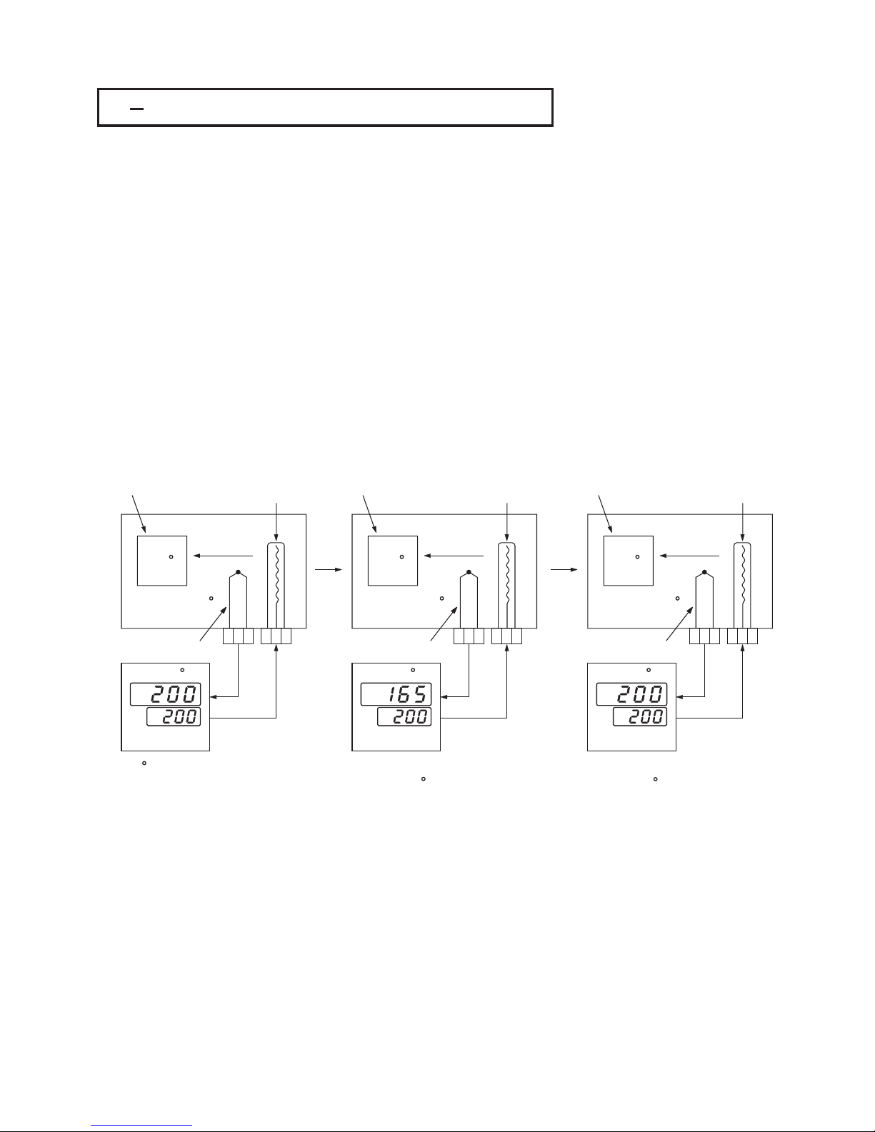
315PV1Shift3 15 PV1 Shift
165 C
C
Heat
Transfer
200 C
Sensor
Subject
Heater
35 C temperature
difference is observed
SHIF= 0
165 C
C
Heat
Transfer
200 C
Sensor
Subject
Heater
Adjust SHIF
SHIF= -35 C
Supply more heat
200 C
C
Heat
Transfer
235 C
Sensor
Subject
Heater
Display is stable
SHIF= -35 C
PV=SV
Figure 3.20
PV1 Shift Application
Figure 3.20
PV1
Shift Application
UM93001C
55
In certain applications it is desirable to shift the controller display value from
its actual value. This can be easily accomplished by using the PV1 shift
function.
In certain applications it is desirable to shift the controller display value from
its actual value. This can be easily accomplished by using the PV1 shift
function.
Press the " scroll " key to the parameter SHIF. The value you adjust here, either
positive or negative, will be added to the actual value. The SHIF function will
.alter PV1 only
Press the " scroll " key to the parameter SHIF. The value you adjust here, either
positive or negative, will be added to the actual value. The SHIF function will
.alter PV1 only
Here is an example. A process is equipped with a heater, a sensor and a
subject to be warmed up. Due to the design and position of the components in
the system, the sensor could not be placed any closer to the part. Thermal
gradient ( different temperature ) is common and necessary to an extent in any
thermal system for heat to be transferred from one point to another. If the
difference between the sensor and the subject is 35 C, and the desired
temperature at the subject to be heated is 200 C, the controlling value or the
temperature at the sensor should be 235 C. You should input -35 C as to
subtract 35 C from the actual process display. This in turn will cause the
controller to energize the load and bring the process display up to the set point
value.
L
L
LL
L
Here is an example. A process is equipped with a heater, a sensor and a
subject to be warmed up. Due to the design and position of the components in
the system, the sensor could not be placed any closer to the part. Thermal
gradient ( different temperature ) is common and necessary to an extent in any
thermal system for heat to be transferred from one point to another. If the
difference between the sensor and the subject is 35 C, and the desired
temperature at the subject to be heated is 200 C, the controlling value or the
temperature at the sensor should be 235 C. You should input -35 C as to
subtract 35 C from the actual process display. This in turn will cause the
controller to energize the load and bring the process display up to the set point
value.
L
L
LL
L
Page 56

3 16 Failure Transfer3 16 Failure Transfer
The controller will enter as one of the following conditions occurs:
1. occurs ( due to the input 1 sensor break or input 1 current below 1mA
if 4-20 mA is selected or input 1 voltage below 0.25V if 1-5 V is selected ) if
PV1, P1-2 or P2-1 is selected for PVMD or PV1 is selected for SPMD.
2. occurs ( due to the input 2 sensor break or input 2 current below 1mA
if 4-20 mA is selected or input 2 voltage below 0.25V if 1-5 V is selected ) if
PV2, P1-2 or P2-1 is selected for PVMD or PV2 is selected for SPMD.
3. occurs due to the A-D converter of the controller fails.
failure mode
SB1E
SB2E
ADER
The controller will enter as one of the following conditions occurs:
1. occurs
( due to the input 1 sensor break or input 1 current below 1mA
if
4-20 mA is selected or input 1 voltage below 0.25V if 1-5 V is selected ) if
PV1,
P1-2 or P2-1 is selected for PVMD or PV1 is selected for SPMD.
2. occurs
( due to the input 2 sensor break or input 2 current below 1mA
if
4-20 mA is selected or input 2 voltage below 0.25V if 1-5 V is selected ) if
PV2,
P1-2 or P2-1 is selected for PVMD or PV2 is selected for SPMD.
3. occurs
due to the A-D converter of the controller fails.
failure
mode
SB1E
SB2E
ADER
The output 1 and output 2 will perform the function as one of the
following conditions occurs:
1. During power starts ( within 2.5 seconds ).
2. The controller enters the failure mode.
3. The controller enters the manual mode.
4. The controller enters the calibration mode.
failure transfer
The output 1 and output 2 will perform the function as one of the
following
conditions occurs:
1.
During power starts ( within 2.5 seconds ).
2.
The controller enters the failure mode.
3.
The controller enters the manual mode.
4.
The controller enters the calibration mode.
failure
transfer
Output 1 Failure Transfer, if activated, will perform :
1. If output 1 is configured as proportional control ( PB1=0),andBPLS is
selected for O1FT, then output 1 will perform bumpless transfer. Thereafter
the previous averaging value of MV1 will be used for controlling output 1.
2. If output 1 is configured as proportional control ( PB1=0),andavalue of
0 to 100.0 % is set for O1FT, then output 1 will perform failure transfer.
Thereafter the value of O1FT will be used for controlling output 1.
3. If output 1 is configured as ON-OFF control ( PB1=0),then output 1 will be
driven OFF if O1FN selects REVR and be driven ON if O1FN selects DIRT.
Output 1 Failure Transfer, if activated, will perform :
1.
If output 1 is configured as proportional control ( PB1 = 0 ), and BPLS is
selected
for O1FT, then output 1 will perform bumpless transfer. Thereafter
the
previous averaging
value of MV1 will
be used for controlling output 1.
2.
If output 1
is configured as proportional
control ( PB1 = 0
), and a value of
0
to 100.0 % is set for O1FT, then output 1 will perform failure transfer.
Thereafter
the value of O1FT will be used for controlling output 1.
3.
If output 1 is configured as ON-OFF control ( PB1 = 0 ), then output 1 will be
driven
OFF if O1FN selects REVR and be driven ON if O1FN selects DIRT.
Output 2 Failure Transfer
Alarm 1 Failure Transfer
, if activated, will perform :
1. If OUT2 selects COOL, and BPLS is selected for O1FT, then output 2 will
perform bumpless transfer. Thereafter the previous averaging value of MV2
will be used for controlling output 2.
2. If OUT2 selects COOL, and a value of 0 to 100.0 % is set for O2FT, then
output 2 will perform failure transfer. Thereafter the value of O1FT will be
used for controlling output 2.
is activated as the controller enters failure mode.
Thereafter the alarm 1 will transfer to the ON or OFF state preset by A1FT.
Output 2 Failure Transfer
Alarm
1 Failure Transfer
,
if activated, will perform :
1.
If OUT2 selects COOL, and BPLS is selected for O1FT, then output 2 will
perform
bumpless transfer. Thereafter the previous averaging value of MV2
will
be used for controlling output 2.
2.
If OUT2 selects COOL, and a value of 0 to 100.0 % is set for O2FT, then
output
2 will perform failure transfer. Thereafter the value of O1FT will be
used
for controlling output 2.
is
activated as the controller enters failure mode.
Thereafter
the alarm 1 will transfer to the ON or OFF state preset by A1FT.
Failure Mode Occurs as :
1. SB1E
2. SB2E
3. ADER
Failure Mode Occurs as :
1.
SB1E
2.
SB2E
3.
ADER
Failure Transfer of outout 1 and output 2
occurs as :
1. Power start ( within 2.5 seconds )
2. Failure mode is activated
3. Manual mode is activated
4. Calibration mode is activated
Failure Transfer of outout 1 and output 2
occurs
as :
1.
Power start ( within 2.5 seconds )
2.
Failure mode is activated
3.
Manual mode is activated
4.
Calibration mode is activated
Failure Transfer of alarm 1 and alarm 2
occurs as :
1. Failure mode is activated
Failure Transfer of alarm 1 and alarm 2
occurs
as :
1.
Failure mode is activated
Failure Transfer Setup :
1. O1FT
2. O2FT
3. A1FT
4. A2FT
Failure Transfer Setup :
1.
O1FT
2.
O2FT
3.
A1FT
4.
A2FT
56
UM93001C
Alarm 2 Failure Transfer is activated as the controller enters failure mode.
Thereafter the alarm 2 will transfer to the ON or OFF state preset by A2FT.
Alarm 2 Failure Transfer is activated as the controller enters failure mode.
Thereafter
the alarm 2 will transfer to the ON or OFF state preset by A2FT.
Exception: If Loop Break (LB) alarm or sensor Break (SENB) alarm is
configured for A1FN, the alarm 1 will be switched to ON state independent
of the setting of A1FT. If Dwell Timer (TIMR) is configured for A1FN, the alarm 1
will not perform failure transfer.
Exception: If Loop Break (LB) alarm or sensor Break (SENB) alarm is
configured
for A1FN, the alarm 1 will be switched to ON state independent
of
the setting of A1FT. If Dwell Timer (TIMR) is configured for A1FN, the alarm 1
will
not perform failure transfer.
Exception: If Loop Break (LB) alarm or sensor Break (SENB) alarm is
configured for A2FN, the alarm 2 will be switched to ON state independent
of the setting of A2FT. If Dwell Timer (TIMR) is configured for A2FN, the alarm 2
will not perform failure transfer.
Exception: If Loop Break (LB) alarm or sensor Break (SENB) alarm is
configured
for A2FN, the alarm 2 will be switched to ON state independent
of
the setting of A2FT. If Dwell Timer (TIMR) is configured for A2FN, the alarm 2
will
not perform failure transfer.
Page 57

3 17 Bumpless Transfer3 17 Bumpless Transfer
The bumpless transfer function is available for output 1 and output 2 ( provided
that OUT2 is configured as COOL ).
is enabled by selecting BPLS for O1FT and/or O2FT and
activated as one of the following cases occurs :
1. Power starts ( within 2.5 seconds ).
2. The controller enters the failure mode. See for failure mode
descriptions.
3. The controller enters the manual mode. See for manual mode
descriptions.
4. The controller enters the calibration mode. See for calibration
mode descriptions.
As the bumpless transfer is activated, the controller will transfer to open-loop
control and uses the previous averaging value of MV1 and MV2 to continue
control.
Bumpless Transfer
Section 3-16
Section 3-22
Chapter 6
The bumpless transfer function is available for output 1 and output 2 ( provided
that
OUT2 is configured as COOL ).
is
enabled by selecting BPLS for O1FT and/or O2FT and
activated
as one of the following cases occurs :
1.
Power starts ( within 2.5 seconds ).
2.
The
controller enters the failure mode. See for
failure
mode
descriptions.
3.
The controller enters the manual mode. See for manual mode
descriptions.
4.
The controller enters the calibration mode. See for calibration
mode
descriptions.
As
the
bumpless transfer is activated, the controller will transfer to open-loop
control
and uses the previous averaging value of MV1 and MV2 to continue
control.
Bumpless
Transfer
Section
3-16
Section
3-22
Chapter
6
Without Bumpless TransferWithout Bumpless Transfer
With Bumpless TransferWith Bumpless Transfer
Power interruptedPower interrupted
Power interruptedPower interrupted
Large
deviation
Large
deviation
Small
deviation
Small
deviation
Sensor breakSensor break
Sensor breakSensor break
Time
Time
Set point
Set point
Set pointSet point
PV
PV
Load varies
Load varies
Since the hardware and software need time to be initialized, the control is
abnormal as the power is recovered and results in a large disturbance to
the process. During the sensor breaks, the process loses power.
Since the hardware and software need time to be initialized, the control is
abnormal
as the power is recovered and results in a large disturbance to
the
process. During the sensor breaks, the process loses power.
After bumpless transfer configured, the correct control variable is applied
immediately as the power is recovered, the disturbance is small. During the
sensor breaks, the controller continues to control by using its previous value. If
the load doesn't change, the process will remain stable. Thereafter, once the
load changes, the process may run away.
For fail safe reason, an additional alarm
should be used to announce the operator when the system fails. For ,
a Sensor Break Alarm, if configured, will switch to failure state and announces
the operator to use manual control or take a proper security action when the
system enters failure mode.
Therefore, you should not rely on a
bumpless transfer for a longer time.
example
After bumpless transfer configured, the correct control variable is applied
immediately
as the power is recovered, the disturbance is small. During the
sensor
breaks, the controller continues to control by using its previous value. If
the
load doesn't change, the process will remain stable. Thereafter, once the
load
changes, the process may run away.
For
fail safe reason, an additional alarm
should
be used to announce the operator when the system fails. For ,
a
Sensor Break Alarm, if configured, will switch to failure state and announces
the
operator to use manual control or take a proper security action when the
system
enters failure mode.
Therefore, you should not rely on a
bumpless
transfer for a longer time.
example
Bumpless Transfer Setup :
1. O1FT = BPLS
2. O2FT = BPLS
Bumpless Transfer Setup :
1.
O1FT = BPLS
2.
O2FT = BPLS
Bumpless Transfer Occurs as :
1. Power Starts ( within 2.5 seconds )
2. Failure mode is activated
3. Manual mode is activated
4. Calibration mode is activated
Bumpless Transfer Occurs as :
1.
Power Starts ( within 2.5 seconds )
2.
Failure mode is activated
3.
Manual mode is activated
4.
Calibration mode is activated
Figure 3.21 Benefits of Bumpless
Transfer
Figure 3.21 Benefits of Bumpless
Transfer
UM93001C
57
Warning :After system fails,
never depend on bumpless
transfer for a long time,
otherwise it might cause a
problem to the system to run
away.
Warning :After system fails,
never
depend on bumpless
transfer
for a long time,
otherwise
it might cause a
problem
to the system to run
away.
Page 58

3 18 Self tuning3 18 Self tuning
Self-tune MenuSelf-tune Menu
Selects
Disable Self-tuning
Disable Self-tuning
Enable Self-tuningEnable Self-tuning
or
58
UM93001C
The Self-tuning which is designed by using an provides an
alternative option for tuning the controller. It is activated as soon as SELF is
selected with YES. When Self-tuning is working, the controller will change its
working PID values and compares the process behavior with previous cycle. If
the new PID values achieve a better control, then changing the next PID values
in the same direction, otherwise, changing the next PID values in reverse
direction. When an optimal condition is obtained, the optimal PID values will be
stored in PB1, TI1, TD1 or PB2, TI2, TD2 which is determined by Event Input
conditions. See . When Self-tuning is completed, the value of SELF
will be changed from YES to NONE to disable self-tuning function.
innovative algorithm
Section 4-1
The Self-tuning which is designed by using an provides an
alternative
option for tuning the controller. It is activated as soon as SELF is
selected
with YES. When Self-tuning is working, the controller will change its
working
PID values and compares the process behavior with previous cycle. If
the
new PID values achieve a better control, then changing the next PID values
in
the same direction, otherwise, changing the next PID values in reverse
direction.
When an optimal condition is obtained, the optimal PID values will be
stored
in PB1, TI1, TD1 or PB2, TI2, TD2 which is determined by Event Input
conditions.
See . When Self-tuning is completed, the value of SELF
will
be changed from YES to NONE to disable self-tuning function.
innovative
algorithm
Section
4-1
When the Self-tuning is enabled, the control variables are tuned slowly so that
the disturbance to the process is less than auto-tuning. Usually, the Self-tuning
will perform successfully with no need to apply additional auto-tuning.
When the Self-tuning is enabled, the control variables are tuned slowly so that
the
disturbance to the process is less than auto-tuning. Usually, the Self-tuning
will
perform successfully with no need to apply additional auto-tuning.
Exceptions: The Self-tuning will be disabled as soon as one of the following
conditions occurs:
1. SELF is selected with NONE.
2. The controller is used for on-off control, that is PB=0.
3. The controller is used for manual reset, that is TI=0.
4. The controller is under loop break condition.
5. The controller is under failure mode (e.g. sensor break).
6. The controller is under manual control mode.
7. The controller is under sleep mode.
8. The controller is being calibrated.
Exceptions: The Self-tuning will be disabled as soon as one of the following
conditions
occurs:
1.
SELF is selected with NONE.
2.
The controller is used for on-off control, that is PB=0.
3.
The controller is used for manual reset, that is TI=0.
4.
The controller is under loop break condition.
5.
The controller is under failure mode (e.g. sensor break).
6.
The controller is under manual control mode.
7.
The controller is under sleep mode.
8.
The controller is being calibrated.
If the self-tuning is enabled, the auto-tuning can still be used any time. The selftuning will use the auto-tuning results for its initial values.
If the self-tuning is enabled, the auto-tuning can still be used any time. The selftuning
will use the auto-tuning results for its initial values.
Unlike auto-tuning, Self-tuning will produce less disturbance to the process.
Unlike auto-tuning, Self-tuning doesn't change control mode during tuning
period. It always performs PID control.
Changing set point during Self-tuning is allowable. Hence, Self-tuning can
be used for ramping set point control as well as remote set point control
where the set point is changed from time to time.
Unlike auto-tuning, Self-tuning will produce less disturbance to the process.
Unlike
auto-tuning, Self-tuning doesn't change control mode during tuning
period.
It always performs PID control.
Changing
set point during Self-tuning is allowable. Hence, Self-tuning can
be
used for ramping set point control as well as remote set point control
where
the set point is changed from time to time.
Benefits of Self-tuning:Benefits of Self-tuning:
1.
2.
3.
Default
SELF=NONE
Default
SELF=NONE
Benefits of Self-tune:
1. Less disturbance to the process.
2. Perform PID control during tuning
period.
3. Available for ramping set point
control and remote set point
control.
Benefits of Self-tune:
1.
Less disturbance to the process.
2.
Perform PID control during tuning
period.
3.
Available for ramping set point
control
and remote set point
control.
Operation:
Section 1-5The parameter SELF is contained in setup menu. Refer to to
obtain SELF for initiating a self-tuning.
Operation:
Section
1-5The parameter SELF is contained in setup menu. Refer to to
obtain
SELF for initiating a self-tuning.
Page 59

3 19 Auto tuning3 19 Auto tuning
The auto-tuning process is performed at set point.
The process will oscillate around the set point during tuning process.
Set a set point to a lower value if overshooting beyond the normal
process value is likely to cause damage.
The auto-tuning process is performed at set point.
The
process will oscillate around the set point during tuning process.
Set
a set point to a lower value if overshooting beyond the normal
process
value is likely to cause damage.
The auto-tuning is applied in cases of :
Initial setup for a new process
The set point is changed substantially from the previous auto-tuning
value
The control result is unsatisfactory
The auto-tuning is applied in cases of :
Initial
setup for a new process
The
set point is changed substantially from the previous auto-tuning
value
The
control result is unsatisfactory
*
*
*
Operation :Operation :
1. The system has been installed normally.
2. Use the default values for PID before tuning.
The default values are : PB1=PB2=18.0 F
TI1=TI2=100 sec, TD1=TD2=25.0 sec, Of course, you can use other
reasonable values for PID before tuning according to your previous
experiences. But don't use a zero value for PB1 and TI1 or PB2 and
TI2, otherwise, the auto-tuning program will be disabled.
1. The system has been installed normally.
2.
Use the default values for PID before tuning.
The
default values are : PB1=PB2=18.0 F
TI1=TI2=100
sec, TD1=TD2=25.0 sec, Of course, you can use other
reasonable
values for PID before tuning according to your previous
experiences.
But don't use a zero value for PB1 and TI1 or PB2 and
TI2,
otherwise, the auto-tuning program will be disabled.
3. Set the set point to a normal operating value or a lower value if
overshooting beyond the normal process value is likely to cause
damage.
3. Set the set point to a normal operating value or a lower value if
overshooting
beyond the normal process value is likely to cause
damage.
4. Press until appears on the display.4. Press until appears on the display.
Applicable Conditions :Applicable Conditions :
PB1=0, TI1=0 if PB1,TI1,TD1
assigned
PB1=0, TI1=0 if PB1,TI1,TD1
assigned
PB2=0, TI2=0, if PB2, TI2, TD2
assigned
PB2=0, TI2=0, if PB2, TI2, TD2
assigned
5. Press for at least 3 seconds. The upper display will begin to flash
and the auto-tuning procedure is beginning.
5. Press for at least 3 seconds. The upper display will begin to flash
and
the auto-tuning procedure is beginning.
NOTE :NOTE :
Procedures:
Any of the ramping function, remote set point or pump function, if used,
will be disabled once auto-tuning is proceeding.
Any of the ramping function, remote set point or pump function, if used,
will
be disabled once auto-tuning is proceeding.
The auto-tuning can be applied either as the process is warming up
or as the process has been in steady state
See Figure 3.22.
( Cold Start ) ( Warm Start ).
The auto-tuning can be applied either as the process is warming up
or
as the process has been in steady state
See
Figure 3.22.
(
Cold Start )(Warm Start ).
If the auto-tuning begins apart from the set point ( Cold Start ), the unit
enters . As the process reaches the set point value, the
unit enters . The waiting cycle elapses a double integral
time ( TI1 or TI2, dependent on the selection, see ) then it
enters a The double integral time is introduced to allow
the process to reach a stable state. Before learning cycle, the unit
performs function with a PID control. While in learning cycle the
unit performs function with an ON-OFF control. Learning
cycle is used to test the characteristics of the process. The data are
measured and used to determine the optimal PID values. At the end of
the two successive ON-OFF cycles the PID values are obtained and
automatically stored in the nonvolatile memory.
After the auto-tuning procedures are completed, the process display
will cease to flash and the unit revert to PID control by using its new PID
values.
During pre-tune stage the PID values will be modified if any unstable
phenomenon which is caused by incorrect PID values is detected.
Without pre-tune stage, like other conventional controller, the tuning
result will be strongly related to the time when the auto-tuning is
applied. Hence different values will be obtained every time as autotuning is completed without pre-tune. It is particularly true when the
auto-tuning are applied by using cold start and warm start.
Warm-up cycle
waiting cycle
learning cycle.
Section 4.1
pre-tune
post-tune
If the auto-tuning begins apart from the set point ( Cold Start ), the unit
enters .
As the process reaches the set point value, the
unit
enters . The waiting cycle elapses a double integral
time
( TI1 or TI2, dependent on the selection, see ) then it
enters
a The double integral time is introduced to allow
the
process to reach a stable state. Before learning cycle, the unit
performs function
with a PID control. While in learning cycle the
unit
performs function with an ON-OFF control. Learning
cycle
is used to test the characteristics of the process. The data are
measured
and used to determine the optimal PID values. At the end of
the
two successive ON-OFF cycles the PID values are obtained and
automatically
stored in the nonvolatile memory.
After
the auto-tuning procedures are completed, the process display
will
cease to flash and the unit revert to PID control by using its new PID
values.
During
pre-tune stage the PID values will be modified if any unstable
phenomenon
which is caused by incorrect PID values is detected.
Without
pre-tune stage, like other conventional controller, the tuning
result
will be strongly related to the time when the auto-tuning is
applied.
Hence different values will be obtained every time as auto-
tuning
is completed without pre-tune. It is particularly true when the
auto-tuning
are applied by using cold start and warm start.
Warm-up
cycle
waiting
cycle
learning
cycle.
Section
4.1
pre-tune
post-tune
UM93001C
59
Pre-tune Function Advantage:
Consistent tuning results can be
obtained
Pre-tune Function Advantage:
Consistent
tuning results can be
obtained
Page 60

Auto-tuning
Begins
Auto-tuning
Begins
Auto-tuning
Begins
Auto-tuning
Begins
Auto-tuning
Complete
Auto-tuning
Complete
Auto-tuning
Complete
Auto-tuning
Complete
PID ControlPID Control
Pre-tune StagePre-tune Stage
Pre-tune StagePre-tune Stage
Pre-tune
Stage
Pre-tune
Stage
Post-tune StagePost-tune Stage
Post-tune StagePost-tune Stage
PID ControlPID Control
ON-OFF ControlON-OFF Control
ON-OFF ControlON-OFF Control
PID ControlPID Control
PID ControlPID Control
Time
Time
Warm-up
Cycle
Warm-up
Cycle
Waiting
Cycle
Waiting
Cycle
Waiting
Cycle
Waiting
Cycle
Learning CycleLearning Cycle
Learning CycleLearning Cycle
New PID CycleNew PID Cycle
New PID CycleNew PID Cycle
=2 Integral
Time
=2 Integral
Time
=2 Integral
Time
=2 Integral
Time
Set PointSet Point
Set PointSet Point
Figure 3.22
Auto-tuning Procedure
Figure 3.22
Auto-tuning
Procedure
PV
PV
Cold StartCold Start
Warm StartWarm Start
If the auto-tuning begins near the set point ( warm start ), the unit passes the
warm-up cycle and enters the waiting cycle. Afterward the procedures are same
as that described for cold start.
If the auto-tuning begins near the set point ( warm start ), the unit passes the
warm-up
cycle and enters the waiting cycle. Afterward the procedures are same
as
that described for cold start.
Auto-Tuning ErrorAuto-Tuning Error
If auto-tuning fails an ATER message will appear on the upper display in cases of :If auto-tuning fails an ATER message will appear on the upper display in cases of :
Solutions toSolutions to
1. Try auto-tuning once again.
2. Don't change set point value during auto-tuning procedure.
3. Don't change event input state during auto-tuning procedure.
4. Use manual tuning instead of auto-tuning. ( See ).
5. Touch any key to reset message.
Section 3-20
1. Try auto-tuning once again.
2.
Don't change set point value during auto-tuning procedure.
3.
Don't change event input state during auto-tuning procedure.
4.
Use manual tuning instead of auto-tuning. ( See ).
5.
Touch any key to reset message.
Section
3-20
If PB exceeds 9000 ( 9000 PU, 900.0 F or 500.0 C ).
or if TI exceeds 1000 seconds.
or if set point is changed during auto-tuning procedure.
or if event input state is changed so that set point value is changed.
LL
If PB exceeds 9000 ( 9000 PU, 900.0 F or 500.0 C ).
or
if TI exceeds 1000 seconds.
or
if set point is changed during auto-tuning procedure.
or
if event input state is changed so that set point value is changed.
LL
60
UM93001C
Auto-Tuning ErrorAuto-Tuning Error
Page 61

3 20 Manual Tuning3 20 Manual Tuning
END
Does
the process
oscillate ?
Does
the process
oscillate ?
Does
the process
oscillate ?
Is
steady state
reached ?
Is
steady state
reached ?
Is
steady state
reached ?
In certain applications ( very few ) using both self-tuning and auto-tuning to
tune a process may be inadequate for the control requirement, then you can
try manual tuning.
Connect the controller to the process and perform the procedures according
to the flow chart shown in the following diagram.
In certain applications ( very few ) using both self-tuning and auto-tuning to
tune
a process may be inadequate for the control requirement, then you can
try
manual tuning.
Connect
the controller to the process and perform the procedures according
to
the flow chart shown in the following diagram.
No
No
No
No
No
No
Yes
Yes
Yes
Yes
Yes
Yes
Yes
Yes
No
No
Use initial PID values
to control the process
Wait and Examine
the Process
Wait and Examine
the Process
Wait and Examine
the Process
0.5PB1 PB1
0 Flag
1.6PB1 PB1 0.8PB1 PB1
1 Flag
2PB1 PB1
Flag=0 ? Flag=1 ?
PB1 PBu
Oscillating period Tu
Load new PID values
1.7 PBu PB1
Tu TI1
0.3 Tu TD1
NOTE :NOTE :
The final PID values can't be zero.
If PBu=0 then set PB1=1.
If Tu < 1 sec, then set TI1=1 sec.
The final PID values can't be zero.
If
PBu=0 then set PB1=1.
If
Tu < 1 sec, then set TI1=1 sec.
The above procedure may take a long time before reaching a new steady state
since the P band was changed. This is particularly true for a slow process. So
the above manual tuning procedures will take from minutes to hours to obtain
optimal PID values.
The above procedure may take a long time before reaching a new steady state
since
the P band was changed. This is particularly true for a slow process. So
the
above manual tuning procedures will take from minutes to hours to obtain
optimal
PID values.
Figure 3.23
Manual Tuning
Procedure
Figure 3.23
Manual
Tuning
Procedure
UM93001C
61
Page 62

The PBu is called the and the period of oscillation Tu is called
the in the flow chart of Figure 3.23 . When this occurs, the
process is called in a . Figure 3.24 shows a critical steady
state occasion.
Ultimate P Band
Ultimate Period
critical steady state
The PBu is called the and the period of oscillation Tu is called
the in
the flow chart of Figure 3.23 . When this occurs, the
process
is called in a.Figure 3.24 shows a critical steady
state
occasion.
Ultimate
P Band
Ultimate
Period
critical
steady state
Set pointSet point
Tu
PV
Time
If PB=PBu
the process sustains to oscillate
If PB=PBu
the
process sustains to oscillate
Figure 3.24 Critical Steady
State
Figure 3.24 Critical Steady
State
If the control performance by using above tuning is still unsatisfactory, the
following rules can be applied for further adjustment of PID values :
If the control performance by using above tuning is still unsatisfactory, the
following
rules can be applied for further adjustment of PID values :
ADJUSTMENT SEQUENCEADJUSTMENT SEQUENCE
SYMPTOM SOLUTION
(1) Proportional Band(P)
PB1 and/or PB2
(1) Proportional Band ( P )
PB1
and/or PB2
(2) Integral Time(I)
TI1 and/or TI2
(2) Integral Time ( I )
TI1
and/or TI2
(3) Derivative Time(D)
TD1 and/or TD2
(3) Derivative Time ( D )
TD1
and/or TD2
Slow ResponseSlow Response
High overshoot or
Oscillations
High overshoot or
Oscillations
Slow ResponseSlow Response
Slow Response or
Oscillations
Slow Response or
Oscillations
Instability or
Oscillations
Instability or
Oscillations
High OvershootHigh Overshoot
Decrease PB1 or PB2Decrease PB1 or PB2
Increase PB1 or PB2Increase PB1 or PB2
Decrease TI1 or TI2Decrease TI1 or TI2
Increase TI1 or TI2Increase TI1 or TI2
Decrease TD1 or TD2Decrease TD1 or TD2
Increase TD1 or TD2Increase TD1 or TD2
Table 3.2 PID Adjustment GuideTable 3.2 PID Adjustment Guide
Figure 3.25 shows the effects of PID adjustment on process response.Figure 3.25 shows the effects of PID adjustment on process response.
Figure 3.25 Effects of PID
Adjustment
Figure 3.25 Effects of PID
Adjustment
PV
Time
P actionP action
Perfect
PB too high
PB too high
PB too lowPB too low
Set pointSet point
62
UM93001C
Page 63
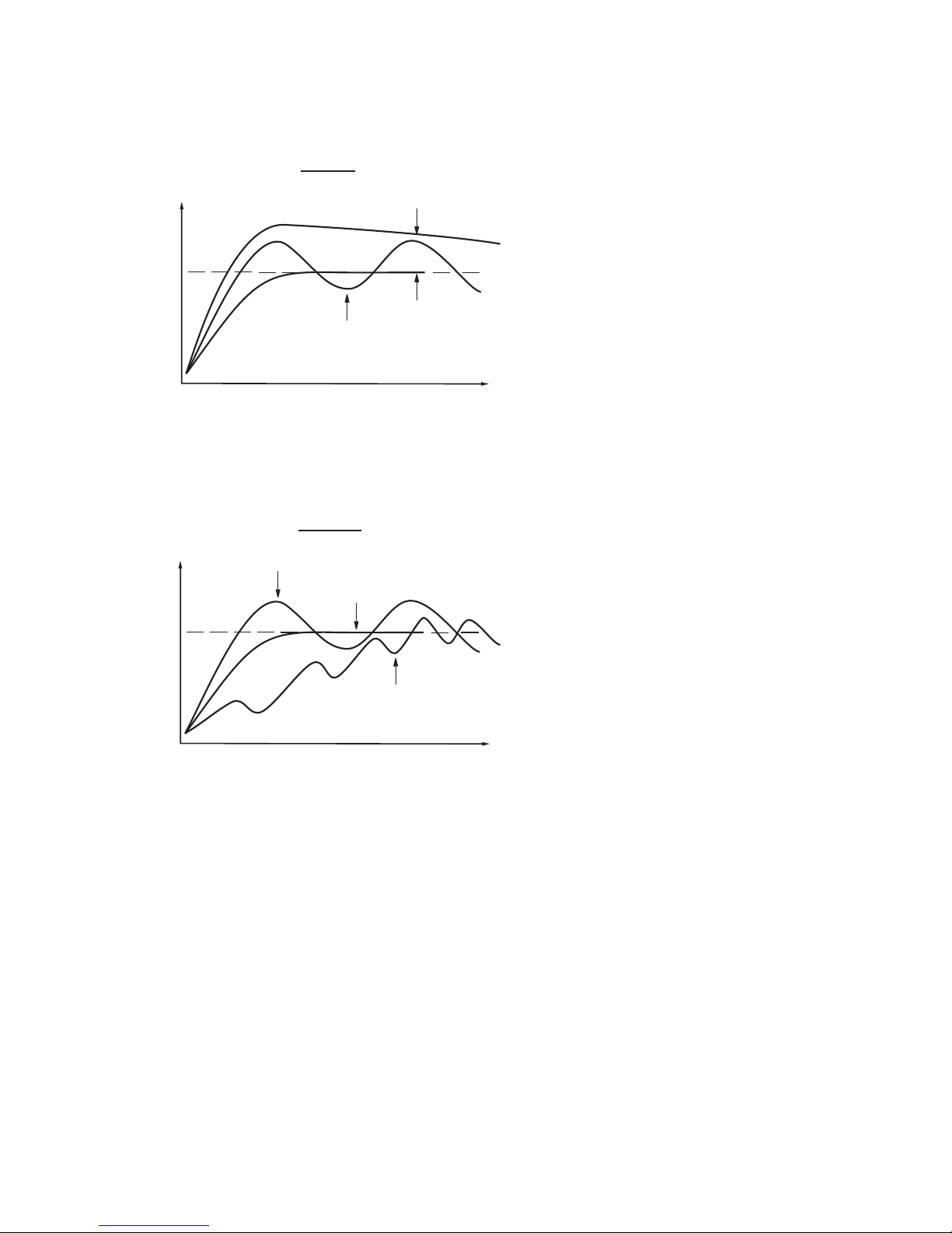
PV
Time
I actionI action
Perfect
TI too low
TI too low
TI too highTI too high
Set pointSet point
PV
Time
D actionD action
Perfect
TD too high
TD too high
TD too lowTD too low
Set pointSet point
UM93001C
63
Figure 3.25 (Continued )
Effects of PID Adjustment
Figure 3.25 (Continued )
Effects
of PID Adjustment
Page 64

3 21 Signal Conditioner DC Power Supply3 21 Signal Conditioner DC Power Supply
Three types of isolated DC power supply are available to supply an external transmitter or
sensor. These are 20V rated at 25mA, 12V rated at 40 mA and 5V rated at 80 mA. The DC
voltage is delivered to the output 2 terminals.
Three types of isolated DC power supply are available to supply an external transmitter or
sensor.
These are 20V rated at 25mA, 12V rated at 40 mA and 5V rated at 80 mA. The DC
voltage
is delivered to the output 2 terminals.
192
10
3114
12
5
13
6147158
16
192
10
3114
12
5
13
6147158
16
192
10
3114
12
5
13
6147158
16
+
+
+ +
+
+ +
4 - 20mA4 - 20mA
Two-line TransmitterTwo-line Transmitter
Three-line Transmitter
or sensor
Three-line Transmitter
or
sensor
VormAV or mA
OUT COM
IN
Bridge Type
Sensor
Bridge Ty pe
Sensor
Caution:
Don't use the DC power supply beyond its rating current to avoid damage.
Purchase a correct voltage to suit your external devices. See ordering code in .Section 1-2
Don't use the DC power supply beyond its rating current to avoid damage.
Purchase
a correct voltage to suit your external devices. See ordering code in .Section 1-2
Figure 3.26
DC Power Supply Applications
Figure 3.26
DC
Power Supply Applications
64
UM93001C
Set
OUT2 =
OUT2 =
DC Power SupplyDC Power Supply
Page 65

3 22 Manual Control3 22 Manual Control
The manual control may be used for the following :purposesThe manual control may be used for the following :purposes
( 1 ) To test the process characteristics to obtain a step response as well as an
impulse response and use these data for tuning a controller.
( 1 ) To test the process characteristics to obtain a step response as well as an
impulse
response and use these data for tuning a controller.
(2)
NOTE
To use manual control instead of a close loop control as the sensor fails or
the controller's A-D converter fails. that a bumpless transfer can not
be used for a longer time. See .Section 3-17
( 2 )
NOTE
To use manual control instead of a close loop control as the sensor fails or
the
controller's A-D converter fails. that a bumpless transfer can not
be
used for a longer time. See .Section 3-17
( 3 ) In certain applications it is desirable to supply a process with a constant
demand.
( 3 ) In certain applications it is desirable to supply a process with a constant
demand.
Operation:
Press until ( Hand Control ) appears on the display.
Press for 3 seconds then the upper display will begin to flash and the lower
display will show . The controller now enters the manual control mode.
Pressing the lower display will show and alternately where
indicates output1(orheating ) control variable value MV1 and
indicates output2(orcooling ) control variable value MV2. Now you can use
up-down key to adjust the percentage values for H or C.
The controller performs open loop control as long as it stays in manual control
mode. The H value is exported to output 1 ( OUT1 ) and C value is exported to
output 2 provided that OUT2 is performing cooling function ( ie. OUT2 selects
COOL ).
Press until ( Hand Control ) appears on the display.
Press
for 3 seconds then the upper display will begin to flash and the lower
display
will show . The controller now enters the manual control mode.
Pressing
the lower display will show and alternately where
indicates
output 1 ( or heating ) control variable value MV1 and
indicates
output 2 ( or cooling ) control variable value MV2. Now you can use
up-down
key to adjust the percentage values for H or C.
The
controller performs open loop control as long as it stays in manual control
mode.
The H value is exported to output 1 ( OUT1 ) and C value is exported to
output
2 provided that OUT2 is performing cooling function ( ie. OUT2 selects
COOL
).
Exception
If OUT1 is configured as ON-OFF control ( ie. PB1=0 if PB1 is assigned or
PB2=0 if PB2 is assigned by event input ), the controller will never perform
manual control mode.
If OUT1 is configured as ON-OFF control ( ie. PB1=0 if PB1 is assigned or
PB2=0
if PB2 is assigned by event input ), the controller will never perform
manual
control mode.
Exit Manual ControlExit Manual Control
To press keys the controller will revert to its previous operating mode
( may be a failure mode or normal control mode ).
To press keys the controller will revert to its previous operating mode
(
may be a failure mode or normal control mode ).
Means
MV1=38.4 %
for OUT1 ( or Heating )
MV1=38.4 %
for
OUT1 ( or Heating )
Means
MV2=7.63 %
for OUT2 ( or Cooling )
MV2=7.63 %
for
OUT2 ( or Cooling )
UM93001C
65
Page 66

3 23 Display Mode3 23 Display Mode
Operation
Press several times until ( Display ) appears on the display.
Then press to enter the display mode. You can select more parameters to
view by pressing or pressing in reverse sequence . The system
mode of the controller and its operation will remain unchanged.
Entering the Display Mode, the upper display will show the parameter value
and the lower display will show the parameter symbol except and
. shows the percentage value for output 1 and shows
the percentage value for output 2 on the lower display while the upper display
shows the current process value.
Press several times until ( Display ) appears on the display.
Then
press to enter the display mode. You can select more parameters to
view
by pressing or pressing in reverse sequence . The system
mode
of the controller and its operation will remain unchanged.
Entering
the Display Mode, the upper display will show the parameter value
and
the lower display will show the parameter symbol except and
.
shows the percentage value for output 1 and shows
the
percentage value for output 2 on the lower display while the upper display
shows
the current process value.
PVHI/PVLO
MV1/MV2
DV
show the historical extreme ( maximum or minimum ) values of
the process on the upper display. The historical extreme values are saved in a
nonvolatile memory even if it is unpowered. Press for at least 6 seconds to
reset both the historical values PVHI and PVLO and begin to record new
peak process values.
show the historical extreme ( maximum or minimum ) values of
the
process on the upper display. The historical extreme values are saved in a
nonvolatile
memory even if it is unpowered. Press for at least 6 seconds to
reset
both the historical values PVHI and PVLO and begin to record new
peak
process values.
show the process value on the upper display and shows
the percentage control value for the output 1, shows the percentage
control value for the output 2.
show the process value on the upper display and shows
the
percentage control value for the output 1, shows the percentage
control
value for the output 2.
PVHI
PVLO
MV1
MV2
DV
PV1
PV2
PB
TI
TD
CJCT
PVR
PVRH
PVRL
PVHI
PVLO
MV1
MV2
DV
PV1
PV2
PB
TI
TD
CJCT
PVR
PVRH
PVRL
shows the difference value between process and set point ( ie. PV-SV ).
This value is used to control the output 1 and output 2.
shows the difference value between process and set point ( ie. PV-SV ).
This
value is used to control the output 1 and output 2.
PV1
shows the process value of input 1 on the upper display.shows the process value of input 1 on the upper display.
PV2
shows the process value of input 2 on the upper display.shows the process value of input 2 on the upper display.
PB
shows the current proportional band value used for control.shows the current proportional band value used for control.
TI
shows the current integral time used for control.shows the current integral time used for control.
TD
shows the current derivative time used for control.shows the current derivative time used for control.
CJCT
PVR
PVRH/PVRL
Since the controller is performing control the values of PB, TI, and
TD may change from time to time.
FUZZYSince the controller is performing control the values of PB, TI, and
TD
may change from time to time.
FUZZY
shows the temperature at the cold junction, measured in C
independent of the unit used.
Lshows the temperature at the cold junction, measured in C
independent
of the unit used.
L
Shows the changing rate of the process in C ( F or PU ) per minute.
It may be negative if the process is going down.
LLShows the changing rate of the process in C (For PU ) per minute.
It
may be negative if the process is going down.
LL
The maximum and minimum changing rate of the process since
power up, are measured in C ( F or PU ) per minute. PVRH is a positive
value while PVRL is a negative value.
LL
The maximum and minimum changing rate of the process since
power
up, are measured in C (For PU ) per minute. PVRH is a positive
value
while PVRL is a negative value.
LL
NOTE
The controller will never revert to its PV/SV display from Display Mode unless
you press the keys.
The controller will never revert to its PV/SV display from Display Mode unless
you
press the keys.
66
UM93001C
Page 67

3 24 Heater Current Monitoring3 24 Heater Current Monitoring
3 25 Reload Default Values3 25 Reload Default Values
A current transformer, CT94-1, should be equipped to measure the heater
current. Select CT for IN2. The input 2 signal conditioner measures the heater
current during the heater is powered and the current value will remain
unchanged during the heater is unpowered. The PV2 will indicate the heater
current. About how to read PV2 value, please refer to Section 3-23.
A current transformer, CT94-1, should be equipped to measure the heater
current.
Select CT for IN2. The input 2 signal conditioner measures the heater
current
during the heater is powered and the current value will remain
unchanged
during the heater is unpowered. The PV2 will indicate the heater
current.
About how to read PV2 value, please refer to Section 3-23.
NOTES
If the heater to be measured is controlled by output 1, then CYC1 should
select 1 second or longer and O1TY should use RELY, SSRD or SSR . Similarly,
if the heater to be measured is controlled by output 2, then CYC2 should
select 1 second or longer and O2TY should use RELY, SSRD or SSR to
provide an adequate time for A to D converter to measure the signal.
Since CT94-1 can detect a full-wave AC current only, a DC or half-wave AC
can't be measured.
If the heater to be measured is controlled by output 1, then CYC1 should
select
1 second or longer and O1TY should use RELY, SSRD or SSR . Similarly,
if
the heater to be measured is controlled by output 2, then CYC2 should
select
1 second or longer and O2TY should use RELY, SSRD or SSR to
provide
an adequate time for A to D converter to measure the signal.
Since
CT94-1 can detect a full-wave AC current only, a DC or half-wave AC
can't
be measured.
Accessory Installed:
CT94-1
Accessory Installed:
CT94-1
Setup
IN2=CT
O1TY or O2TY=RELY, SSRD or SSR
CYC1 or CYC2 >1 sec
Setup
IN2=CT
O1TY
or O2TY=RELY, SSRD or SSR
CYC1
or CYC2 >1 sec
Limitations
1. Linear output type can't be used.
2. CYC1 ( or CYC2 ) should select 1
second or longer to detect heater
current reliably.
3. Only full-wave AC current can be
detected.
Limitations
1.
Linear output type can't be used.
2.
CYC1 ( or CYC2 ) should select 1
second
or longer to detect heater
current
reliably.
3.
Only full-wave AC current can be
detected.
The default values listed in Table 1.4 are stored in the memory as the product
leaves the factory. In certain occasions it is desirable to retain these values
after the parameter values have been changed. Here is a convenient tool to
reload the default values.
The default values listed in Table 1.4 are stored in the memory as the product
leaves
the factory. In certain occasions it is desirable to retain these values
after
the parameter values have been changed. Here is a convenient tool to
reload
the default values.
Operation
Press several times until . Then press . The upper
display will show .Use up-down key to select 0 to 1. If C unit is
required, select 0 for FILE and if F unit is required, select 1 for FILE. Then
Press for at least 3 seconds. The display will flash a moment and the default
values are reloaded.
L
L
Press several times until . Then press . The upper
display
will show .Use up-down key to select 0 to 1. If C unit is
required,
select 0 for FILE and if F unit is required, select 1 for FILE. Then
Press
for at least 3 seconds. The display will flash a moment and the default
values
are reloaded.
L
L
CAUTION
The procedures mentioned above will change the previous setup data. Before
doing so, make sure that if it is really required.
The procedures mentioned above will change the previous setup data. Before
doing
so, make sure that if it is really required.
FILE 0
C Default FileL
FILE 0
C
Default FileL
FILE 1
F Default FileL
FILE 1
F
Default FileL
UM93001C
67
Page 68

Chapter 4 Programming the Full FunctionChapter 4 Programming the Full Function
4 1 Event Input4 1 Event Input
68
UM93001C
Refer to for wiring an event input.
The Event input accepts a digital type signal. types of signal : relay
or switch contacts, open collector pull low and TTL logic level, can be
used to switch the event input.
Section 2-10
Three (1)
(2) (3)
Refer to for wiring an event input.
The
Event input accepts a digital type signal. types of signal : relay
or
switch contacts, open collector pull low and TTL logic level, can be
used
to switch the event input.
Section
2-10
Three (1)
(2) (3)
One of ten functions can be chosen by using ( EIFN ) contained in
setup menu.
One of ten functions can be chosen by using ( EIFN ) contained in
setup
menu.
NONE : Event input no function
If chosen, the event input function is disabled. The controller will use PB1, TI1
and TD1 for PID control and SP1 ( or other values determined by SPMD ) for
the set point.
NONE : Event input no function
If chosen, the event input function is disabled. The controller will use PB1, TI1
and
TD1 for PID control and SP1 ( or other values determined by SPMD ) for
the
set point.
SP2: If chosen, the SP2 will replace the role of SP1 for control.SP2: If chosen, the SP2 will replace the role of SP1 for control.
PID2: If chosen, the second PID set PB2, TI2 and TD2 will be used to replace
PB1, TI1 and TD1 for control.
PID2: If chosen, the second PID set PB2, TI2 and TD2 will be used to replace
PB1,
TI1 and TD1 for control.
SP.P2: If chosen, the SP2, PB2, TI2 and TD2 will replace SP1, PB1, TI1 and
TD1 for control.
SP.P2: If chosen, the SP2, PB2, TI2 and TD2 will replace SP1, PB1, TI1 and
TD1
for control.
Event input
Event input
+Event input
Event
input
+
14
13
EIFN
Terminals:
0 NONE
1 SP2
2 PID2
3 SP.P2
4 RS.A1
5 RS.A2
6 R.A1.2
7 D.O1
8 D.O2
9 D.O1.2
10 LOCK
0 NONE
1
SP2
2
PID2
3
SP.P2
4
RS.A1
5
RS.A2
6
R.A1.2
7
D.O1
8
D.O2
9
D.O1.2
10
LOCK
RS.A1: Reset Alarm 1 as the event input is activated. However, if alarm 1
condition is still existent, the alarm 1 will be retriggered again while the event
input is released.
RS.A1: Reset Alarm 1 as the event input is activated. However, if alarm 1
condition
is still existent, the alarm 1 will be retriggered again while the event
input
is released.
RS.A2: Reset Alarm 2 as the event input is activated. However, if alarm 2
condition is still existent, the alarm 2 will be retriggered again while the event
input is released.
RS.A2: Reset Alarm 2 as the event input is activated. However, if alarm 2
condition
is still existent, the alarm 2 will be retriggered again while the event
input
is released.
R.A1.2: Reset both Alarm 1 and Alarm 2 as the event input is activated.
However, if the alarm 1 and/or alarm 2 are still existent, the alarm 1 and/or
alarm 2 will be triggered again while the event input is released.
R.A1.2: Reset both Alarm 1 and Alarm 2 as the event input is activated.
However,
if the alarm 1 and/or alarm 2 are still existent, the alarm 1 and/or
alarm
2 will be triggered again while the event input is released.
The RS.A1, RS.A2 and R.A1.2 are particularly suitable to be used for a
Latching and/or Latching/Holding alarms.
The RS.A1, RS.A2 and R.A1.2 are particularly suitable to be used for a
Latching
and/or Latching/Holding alarms.
D.O1: Disable Output 1 as the event input is activated. The output 1 control
variable MV1 is cleared to zero.
D.O1: Disable Output 1 as the event input is activated. The output 1 control
variable
MV1 is cleared to zero.
D.O2: Disable Output 2 as the event input is activated. The output 2 control
variable MV2 is cleared to zero.
D.O2: Disable Output 2 as the event input is activated. The output 2 control
variable
MV2 is cleared to zero.
D.O1.2: Disable both Output 1 and Output 2 by clearing MV1 and MV2 values
as soon as the event input is activated.
D.O1.2: Disable both Output 1 and Output 2 by clearing MV1 and MV2 values
as
soon as the event input is activated.
When any of D.O1, D.O2 or D.O1.2 is selected for EIFN, the output 1 and/or
output 2 will revert to their normal conditions as soon as the event input is
released.
When any of D.O1, D.O2 or D.O1.2 is selected for EIFN, the output 1 and/or
output
2 will revert to their normal conditions as soon as the event input is
released.
NOTE: Auto-tuning Self-tuningIf the second PID set is chosen during and/or
procedures, the new PID values will be stored in PB2, TI2 and TD2.
NOTE: Auto-tuning Self-tuningIf
the second PID set is chosen during and/or
procedures,
the new PID values will be stored in PB2, TI2 and TD2.
LOCK: Section
4-13
All parameters are locked to prevent from being changed. See
for more details.
LOCK: Section
4-13
All parameters are locked to prevent from being changed. See
for
more details.
Page 69

UM93001C
69
4 2 Second Set Point4 2 Second Set Point
In certain applications it is desirable to change the set point automatically
without the need to adjust the set point. You can apply a signal to event input
terminals ( pin 14 and pin 13 ).The signal applied to event input may come
from a , a , an , a or other devices. Select
SP2 for EIFN which is contained in setup menu.
This is available only with the case that SP1.2, MIN.R or HR.R is used for
SPMD, where MIN.R and HR.R are used for the ramping function.
See
Timer PLC Alarm Relay Manual Switch
Section 4-4.
In certain applications it is desirable to change the set point automatically
without
the need to adjust the set point. You can apply a signal to event input
terminals
( pin 14 and pin 13 ).The signal applied to event input may come
from
a,a,an , aorother devices. Select
SP2
for EIFN which is contained in setup menu.
This
is available only with the case that SP1.2, MIN.R or HR.R is used for
SPMD,
where MIN.R and HR.R are used for the ramping function.
See
Timer PLC Alarm
Relay Manual Switch
Section
4-4.
Application 1: A process is required to be heated at a higher temperature as
soon as its pressure exceeds a certain limit. Set SPMD=SP1.2, EIFN=SP2 ( or
SP.P2 if the second PID is required for the higher temperature too ).
The pressure gauge is switched ON as it senses a higher pressure. Connect
the output contacts of the pressure gauge to the event input. SP1 is set with a
normal temperature and SP2 is set with a higher temperature. Choose ACTU
for SP2F.
Application 1: A process is required to be heated at a higher temperature as
soon
as its pressure exceeds a certain limit. Set SPMD=SP1.2, EIFN=SP2 ( or
SP.P2
if the second PID is required for the higher temperature too ).
The
pressure gauge is switched ON as it senses a higher pressure. Connect
the
output contacts of the pressure gauge to the event input. SP1 is set with a
normal
temperature and SP2 is set with a higher temperature. Choose ACTU
for
SP2F.
Application 2: An oven is required to be heated at 300 C from eight o'clock
AM to six o'clock PM. After six o'clock PM it is desirable to be maintained at
80 C. Use a programmable 24 hours cycle timer for this purpose. The timer
output is used to control event input. Set SPMD=SP1.2, and EIFN=SP2 ( or
SP.P2 if the second PID is required to be used for the second set point ).
L
L
Application 2: An oven is required to be heated at 300 C from eight o'clock
AM
to six o'clock PM. After six o'clock PM it is desirable to be maintained at
80 C.
Use a programmable 24 hours cycle timer for this purpose. The timer
output
is used to control event input. Set SPMD=SP1.2, and EIFN=SP2 ( or
SP.P2
if the second PID is required to be used for the second set point ).
L
L
Event input +
Event input
Event input +
Event
input
14
13
Apply Signal ToApply Signal To
Setup
EIFN choose SP2 or SP.P2EIFN choose SP2 or SP.P2
Availability
SPMD chooseSPMD choose
or
or
SP2F Function: Define format of SP2 value . If SP2F in the setup menu is
selected with ACTU, the event input function will use SP2 value for its second
set point. If SP2F is selected with DEVI, the SP1 value will be added to SP2.
The sum of SP1 and SP2 (SP1+SP2) will be used by the event input function
for the second set point value. In certain applications it is desirable to move
second set point value with respect to set point 1 value. The DEVI function for
SP2 provides a convenient way in this case.
SP2F Function: Define format of SP2 value . If SP2F in the setup menu is
selected
with ACTU, the event input function will use SP2 value for its second
set
point. If SP2F is selected with DEVI, the SP1 value will be added to SP2.
The
sum of SP1 and SP2 (SP1+SP2) will be used by the event input function
for
the second set point value. In certain applications it is desirable to move
second
set point value with respect to set point 1 value. The DEVI function for
SP2
provides a convenient way in this case.
Modification from RS-232 to Event input:
must
Section 2-16
Because of limitation of pin number, pin 14 is used for both Event input and
RS-232. If you want to change function of BTC-9300 from RS-232 to event
input, you modify jumper JP22 on terminal board by opening jumper J1
and shorting jumper J2. Refer to for the location of JP22.
Modification from RS-232 to Event input:
must
Section
2-16
Because
of limitation of pin number, pin 14 is used for both Event input and
RS-232.
If you want to change function of BTC-9300 from RS-232 to event
input,
you modify jumper JP22 on terminal board by opening jumper J1
and
shorting jumper J2. Refer to for the location of JP22.
SP2F=Format of SP2 Value
ACTU: SP2 is an actual value
DEVI: SP2 is a deviation value
SP2F=Format of SP2 Value
ACTU:
SP2 is an actual value
DEVI:
SP2 is a deviation value
SP1 is set with 300 C and SP2 is set with 80 C. Choose ACTU for SP2F. After
six o'clock PM the timer output is closed. The event input function will select
SP2 ( =80 C) to control the process.
LL
L
SP1 is set with 300 C and SP2 is set with 80 C. Choose ACTU for SP2F. After
six
o'clock PM the timer output is closed. The event input function will select
SP2
( =80 C) to control the process.
LL
L
Refer to for more descriptions about function.Section 4-1 SP2FRefer to for more descriptions about function.Section 4-1 SP2F
Format of SP2 Value
SP2F choose
Format of SP2 Value
SP2F
choose
Actual ValueActual Value
or Deviation Valueor Deviation Value
Page 70

4 3 Second PID Set4 3 Second PID Set
In certain applications the process characteristics is strongly related to its
process value. The BTC-9300 provides two set of PID values. When the
process is changed to different set point, the PID values can be switched to
another set to achieve an optimum condition.
In certain applications the process characteristics is strongly related to its
process
value. The BTC-9300 provides two set of PID values. When the
process
is changed to different set point, the PID values can be switched to
another
set to achieve an optimum condition.
Event input +
Event input
Event input +
Event
input
14
13
Apply Signal ToApply Signal To
Setup
EIFN choose PID2 or SP.P2EIFN choose PID2 or SP.P2
70
UM93001C
Choose for then both set point and PID values will be switched to
another set simultaneously. The signal applied to event input may come from
a Timer, a PLC, an Alarm Relay, a Manual Switch or other devices.
SP.P2 EIFNChoose for then both set point and PID values will be switched to
another
set simultaneously. The signal applied to event input may come from
a
Timer, a PLC, an Alarm Relay, a Manual Switch or other devices.
SP.P2 EIFN
Application 1: Programmed by Set PointApplication 1: Programmed by Set Point
Application 2: Programmed by Process ValueApplication 2: Programmed by Process Value
Auto-tuning Second PIDAuto-tuning Second PID
If the process value exceeds a certain limit, 500 C for example, it is desirable
to use another PID values to optimize the control performance. You can use a
process high alarm to detect the limit of the process value. Choose PV1H for
A1FN, A1MD selects NORM, adjust A1SP to be equal to 500 C, and choose
PID2 for EIFN. If the temperature is higher than 500 C, then alarm 1 is
activated. The alarm 1 output is connected to event input, the PID values will
change from PB1, TI1 and TD1 to PB2, TI2 and TD2.
If the process value exceeds a certain limit, 500 C for example, it is desirable
to
use another PID values to optimize the control performance. You can use a
process
high alarm to detect the limit of the process value. Choose PV1H for
A1FN,
A1MD selects NORM, adjust A1SP to be equal to 500 C, and choose
PID2
for EIFN. If the temperature is higher than 500 C, then alarm 1 is
activated.
The alarm 1 output is connected to event input, the PID values will
change
from PB1, TI1 and TD1 to PB2, TI2 and TD2.
The optimal PID values for a process may vary with its process value and set
point. Hence if a process is used for a wide range of set point, dual PID values
are necessary to optimize the control performance. If the first PID set is
selected ( event input is not applied ) during auto-tuning procedure, the PID
values will be stored in PB1, TI1 and TD1. Similarly, if the second PID set is
selected ( event input is applied while PID2 or SP.P2 is selected for EIFN )
during auto-tuning, the PID values will be stored in PB2, TI2 and TD2 as soon
as auto-tuning is completed.
The optimal PID values for a process may vary with its process value and set
point.
Hence if a process is used for a wide range of set point, dual PID values
are
necessary to optimize the control performance. If the first PID set is
selected
( event input is not applied ) during auto-tuning procedure, the PID
values
will be stored in PB1, TI1 and TD1. Similarly, if the second PID set is
selected
( event input is applied while PID2 or SP.P2 is selected for EIFN )
during
auto-tuning, the PID values will be stored in PB2, TI2 and TD2 as soon
as
auto-tuning is completed.
EIFN= SP.P2EIFN= SP.P2
EIFN= PID2EIFN= PID2
Alarm output Controls the Event
input
Alarm output Controls the Event
input
Refer to Section 5-9 for more details.Refer to Section 5-9 for more details.
See Section 5-9See Section 5-9
Page 71

UM93001C
71
4 4 Ramp&Dwell4 4 Ramp & Dwell
Ramp
The ramping function is performed during power up as well as any time the set
point is changed. Choose MINR or HRR for SPMD, the unit will perform the
ramping function. The ramp rate is programmed by using RAMP which is
contained in user menu.
The ramping function is performed during power up as well as any time the set
point
is changed. Choose MINR or HRR for SPMD, the unit will perform the
ramping
function. The ramp rate is programmed by using RAMP which is
contained
in user menu.
Example without Dwell TimerExample without Dwell Timer
Select MINR for SPMD, IN1U selects C, DP1 selects 1-DP, Set RAMP=10.0.
SP1 is set to 200 C initially, and changed to 100 C after 30 minutes since
power up. The starting temperature is 30 C. After power up the process is
running like the curve shown below:
Select MINR for SPMD, IN1U selects C, DP1 selects 1-DP, Set RAMP=10.0.
SP1
is set to 200 C initially, and changed to 100 C after 30 minutes since
power
up. The starting temperature is 30 C. After power up the process is
running
like the curve shown below:
200C200
C
100C100
C
30C30
C
17
30 40
Time
(minutes)
Time
(minutes)
PV
0
Time (minutes)Time (minutes)
Note: When the ramp function is used, the lower display will show the current
ramping value. However it will revert to show the set point value as soon as the
up or down key is touched for adjustment. The ramping value is initiated to
process value either power up or RAMP and /or set point are changed. Setting
RAMP to zero means no ramp function at all.
Note: When the ramp function is used, the lower display will show the current
ramping
value. However it will revert to show the set point value as soon as the
up
or down key is touched for adjustment. The ramping value is initiated to
process
value either power up or RAMP and /or set point are changed. Setting
RAMP
to zero means no ramp function at all.
SPMD ChooseSPMD Choose
or
Unit / minute
Unit / minute
Unit / hourUnit / hour
Adjust
Adjust
RAMP
Figure 4.1 RAMP FunctionFigure 4.1 RAMP Function
A1FN or A2FN ChooseA1FN or A2FN Choose
TIMER
TIME
Dwell
The Dwell timer can be used separately or accompanied with a Ramp. If A1FN
selects TIMR, the alarm 1 will act as a dwell timer. Similarly, alarm 2 will act as
a dwell timer if A2FN selects TIMR. The timer is programmed by using TIME
which is contained in user menu. The Timer starts to count as soon as the
process reaches its set point, and triggers an alarm as time out. Here is an
example.
The Dwell timer can be used separately or accompanied with a Ramp. If A1FN
selects
TIMR, the alarm 1 will act as a dwell timer. Similarly, alarm 2 will act as
a
dwell timer if A2FN selects TIMR. The timer is programmed by using TIME
which
is contained in user menu. The Timer starts to count as soon as the
process
reaches its set point, and triggers an alarm as time out. Here is an
example.
Example without RampExample without Ramp
28
minutes
28
minutes
40
minutes
40
minutes
Alarm 1 OFFAlarm 1 OFF
Alarm 1 ONAlarm 1 ON
TIME changed to 40.0TIME changed to 40.0
200 F200 F
PV reaches set pointPV reaches set point
SP1 changed to 200 FSP1 changed to 200 F
PV
Figure 4.2 Dwell TimerFigure 4.2 Dwell Timer
Select TIMR for A1FN, IN1U selects F, DP1 selects NODP, Set TIME=30.0
SP1 is set to 400 F initially, and corrected to 200 F before the process
reaches 200 F. As the process reaches set point ( ie. 200 F ) the timer starts
to count. The TIME value can still be corrected without disturbing the Timer
before time out. The TIME is changed to 40.0 after 28 minutes since the
process reached its set point. The behavior of process value and alarm 1 are
shown below.
Select TIMR for A1FN, IN1U selects F, DP1 selects NODP, Set TIME=30.0
SP1
is set to 400 F initially, and corrected to 200 F before the process
reaches
200 F. As the process reaches set point ( ie. 200 F ) the timer starts
to
count. The TIME value can still be corrected without disturbing the Timer
before
time out. The TIME is changed to 40.0 after 28 minutes since the
process
reached its set point. The behavior of process value and alarm 1 are
shown
below.
Page 72

72
UM93001C
Once the timer output was energized it will remain unchanged until power
down or an event input programmed for resetting alarm is applied.
Once the timer output was energized it will remain unchanged until power
down
or an event input programmed for resetting alarm is applied.
Note: The TIMR can't be chosen for both A1FN and A2FN simultaneously,
otherwise an error code will produce.
Note: The TIMR can't be chosen for both A1FN and A2FN simultaneously,
otherwise
an error code will produce.
Ramp & DwellRamp & Dwell
A ramp may be accompanied with a dwell timer to control the process. Here is
an example.
A ramp may be accompanied with a dwell timer to control the process. Here is
an
example.
Example with Ramp & DwellExample with Ramp & Dwell
Select HRR for SPMD, IN1U selects PU, DP1 select 2-DP, Set RAMP=60.00
A2FN selects TIMR, Set TIME=20.0 As power is applied the process value
starts from 0.00 and set SP1=30.00, SP2=40.00. The timer output is used to
control event input.
Select HRR for SPMD, IN1U selects PU, DP1 select 2-DP, Set RAMP=60.00
A2FN
selects TIMR, Set TIME=20.0 As power is applied the process value
starts
from 0.00 and set SP1=30.00, SP2=40.00. The timer output is used to
control
event input.
30
50 60
Time (minutes)
Time (minutes)
PV
0
40.00
30.00
PV
Alarm 2 OFFAlarm 2 OFF
Alarm 2 ONAlarm 2 ON
Figure 4.3 RampFigure 4.3 Ramp
Accompanied with a Dwell TimerAccompanied with a Dwell Timer
Error Code.Error Code.
Page 73

UM93001C
73
4 5 Remote Set Point4 5 Remote Set Point
SPMD selecting PV1 or PV2 will enable the BTC-9300 to accept a remote set
point signal. If PV1 is selected for SPMD, the remote set point signal is sent to
Input 1, and Input 2 is used for process signal input. If PV2 is selected for
SPMD, the remote set point signal is sent to Input 2, and Input 1 is used for
process signal. To achieve this, set the following parameters in the Setup
menu.
SPMD selecting PV1 or PV2 will enable the BTC-9300 to accept a remote set
point
signal. If PV1 is selected for SPMD, the remote set point signal is sent to
Input
1, and Input 2 is used for process signal input. If PV2 is selected for
SPMD,
the remote set point signal is sent to Input 2, and Input 1 is used for
process
signal. To achieve this, set the following parameters in the Setup
menu.
Case 1: Use Input 2 to accept remote set pointCase 1: Use Input 2 to accept remote set point
Case 2: Use Input 1 to accept remote set pointCase 2: Use Input 1 to accept remote set point
FUNC=FULL
IN2, IN2U, DP2, IN2L, IN2H, are set according to remote signal.
PVMD=PV1
IN1, IN1U, DP1, are set according to the process signal
IN1L, IN1H if available, are set according to the process signal
SPMD= PV2
FUNC=FULL
IN2,
IN2U, DP2, IN2L, IN2H, are set according to remote signal.
PVMD=PV1
IN1,
IN1U, DP1, are set according to the process signal
IN1L,
IN1H if available, are set according to the process signal
SPMD=
PV2
FUNC=FULL
IN1, IN1U, DP1, IN1L, IN1H, are set according to remote signal.
PVMD=PV2
IN2, IN2U, DP2, are set according to the process signal
IN2L, IN2H if available, are set according to the process signal
SPMD= PV1
FUNC=FULL
IN1,
IN1U, DP1, IN1L, IN1H, are set according to remote signal.
PVMD=PV2
IN2,
IN2U, DP2, are set according to the process signal
IN2L,
IN2H if available, are set according to the process signal
SPMD=
PV1
Note: If PV1 are chosen for both SPMD and PVMD, an Error Code will
appear. If PV2 are chosen for both SPMD and PVMD, an Error Code
will appear. You should not use these cases, otherwise, the BTC-9300 will not
control properly.
Note: If PV1 are chosen for both SPMD and PVMD, an Error Code will
appear.
If PV2 are chosen for both SPMD and PVMD, an Error Code
will
appear. You should not use these cases, otherwise, the BTC-9300 will not
control
properly.
Setup
FUNC=FULL
SPMD=PV2, PVMD=PV1
or SPMD=PV1, PVMD=PV2
FUNC=FULL
SPMD=PV2,
PVMD=PV1
or
SPMD=PV1, PVMD=PV2
Error MessageError Message
Page 74
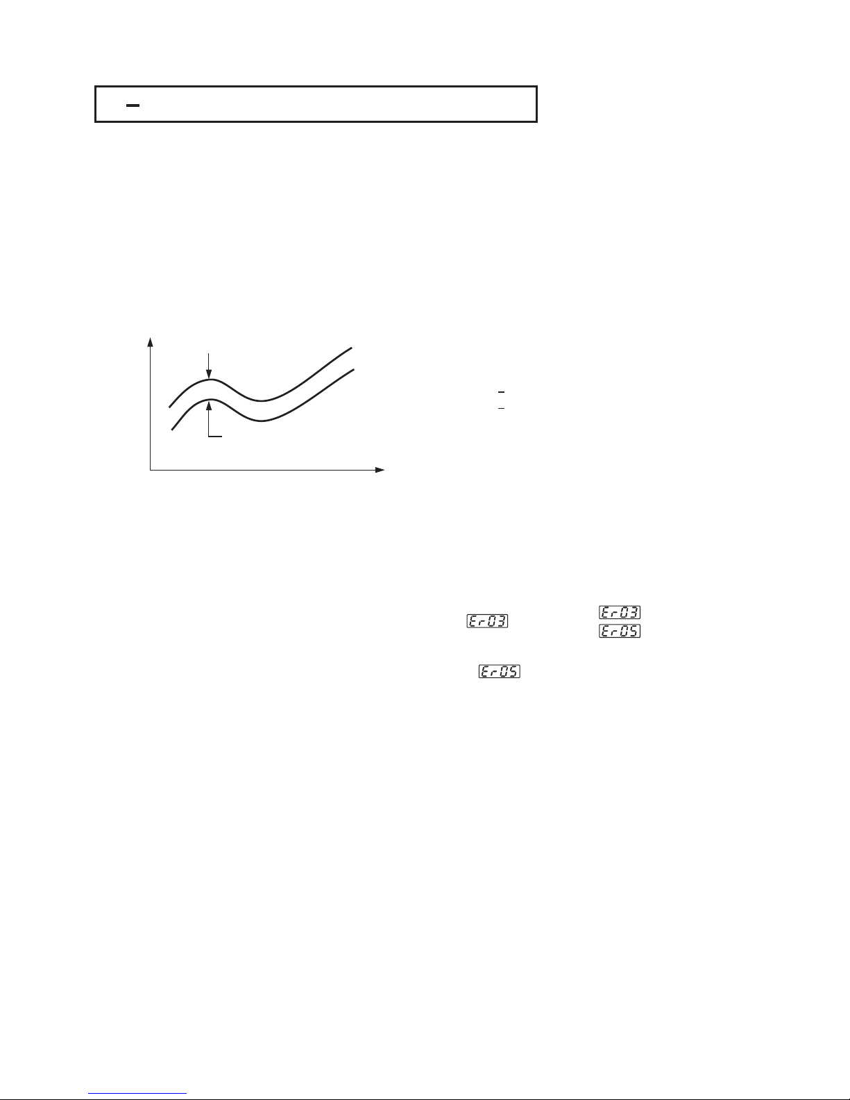
74
UM93001C
4 6 Differential Control4 6 Differential Control
In certain applications it is desirable to control a second process such that its
process value always deviates from the first process with a constant value. To
achieve this, set the following parameter in the Setup menu.
In certain applications it is desirable to control a second process such that its
process
value always deviates from the first process with a constant value. To
achieve
this, set the following parameter in the Setup menu.
FUNC=FULL
IN1,IN1L,IN1H are set according to input 1 signal
IN2,IN2L,IN2H are set according to input 2 signal
IN1U, DP1, IN2U, DP2, are set according to input 1 and input 2 signal
PVMD=P1-2 or P2-1
SPMD=SP1.2
FUNC=FULL
IN1,IN1L,IN1H
are set according to input 1 signal
IN2,IN2L,IN2H
are set according to input 2 signal
IN1U,
DP1, IN2U, DP2, are set according to input 1 and input 2 signal
PVMD=P1-2
or P2-1
SPMD=SP1.2
The response of PV2 will be parallel to PV1 as shown in the following diagramThe response of PV2 will be parallel to PV1 as shown in the following diagram
Time
PV
=Set point=Set point
PV1
PV2
PV=PV1 PV2
or PV2 PV1
Set point=SP1 or SP2
PV=PV1 PV2
or
PV2 PV1
Set
point=SP1 or SP2
The PV display will indicate PV1-PV2 value if P1-2 is chosen for PVMD, or
PV2-PV1 value if P2-1 is chosen for PVMD. If you need PV1 or PV2 to be
displayed instead of PV, you can use the Display Mode to select PV1 or PV2 to
be viewed. See Section 3-23.
The PV display will indicate PV1-PV2 value if P1-2 is chosen for PVMD, or
PV2-PV1
value if P2-1 is chosen for PVMD. If you need PV1 or PV2 to be
displayed
instead of PV, you can use the Display Mode to select PV1 or PV2 to
be
viewed. See Section 3-23.
Setup
PVMD=P1-2
or PVMD=P2-1
PVMD=P1-2
or
PVMD=P2-1
Error MessageError Message
Figure 4.4
Relation between PV1 and PV2
for a Differential Control
Figure 4.4
Relation
between PV1 and PV2
for
a Differential Control
If PVMD selects P1-2 or P2-1, while SPMD selects PV1 or PV2, an
Error Code will appear.
If PVMD selects P1-2 or P2-1, while SPMD selects PV1 or PV2, an
Error
Code will appear.
SPMD=SP1.2
In this case the signals used for input 1 and input 2 should be the same unit
and same decimal point, that is, IN1U=IN2U, DP1=DP2, otherwise
Error Code will appear.
In this case the signals used for input 1 and input 2 should be the same unit
and
same decimal point, that is, IN1U=IN2U, DP1=DP2, otherwise
Error
Code will appear.
Error MessagesError Messages
Page 75

UM93001C
75
4 7 Output Power Limits4 7 Output Power Limits
In certain system the heater ( or cooler ) is over-designed such that the
process is too heavily heated or cooled. To avoid an excessive overshoot
and/or undershoot you can use the Power Limit function.
Output 1 power limit PL1 is contained in User Menu. If output 2 is not used for
cooling ( that is COOL is not selected for OUT2 ), then PL2 is . If the
controller is used for ON-OFF control, then both PL1 and PL2 are
hidden
hidden.
In certain system the heater ( or cooler ) is over-designed such that the
process
is too heavily heated or cooled. To avoid an excessive overshoot
and/or
undershoot you can use the Power Limit function.
Output
1 power limit PL1 is contained in User Menu. If output 2 is not used for
cooling
( that is COOL is not selected for OUT2 ), then PL2 is . If the
controller
is used for ON-OFF control, then both PL1 and PL2 are
hidden
hidden.
Operation:
Press for 3 seconds, then press several times to reach PL1 and PL2.
The PL1 and PL2 are adjusted by using up-down keys with range 0 - 100%.
Press for 3 seconds, then press several times to reach PL1 and PL2.
The
PL1 and PL2 are adjusted by using up-down keys with range 0 - 100%.
Example:
OUT2=COOL, PB1=10.0 C, CPB=50, PL1=50, PL2=80
The output 1 and output 2 will act as following curves:
LOUT2=COOL, PB1=10.0 C, CPB=50, PL1=50, PL2=80
The
output 1 and output 2 will act as following curves:
L
PV
10 C10 C
MV1
100%
50%
OUT1
PV
MV2
100%
80%
5C5 C
OUT2
NOTE:
The adjusting range of MV1(H)andMV2(C)formanual control and/or failure
transfer are not limited by PL1 and PL2.
NOTE:
The
adjusting range of MV1 ( H ) and MV2 ( C ) for manual control and/or failure
transfer
are not limited by PL1 and PL2.
Figure 4.5
Power Limit Function
Figure 4.5
Power
Limit Function
Menu
PL1
PL2
PL1
PL2
Page 76

76
UM93001C
4 8 Data Communication4 8 Data Communication
Two types of interface are available for Data Communication. These are
and interface. Since RS-485 uses a differential architecture to
drive and sense signal instead of a single ended architecture which is used for
RS-232, RS-485 is less sensitive to the noise and suitable for a longer
distance communication. RS-485 can communicate without error over 1 km
distance while RS-232 is not recommended for a distance over 20 meters.
RS-485 RS-232
Tw o types of interface are available for Data Communication. These are
and interface.
Since RS-485 uses a differential architecture to
drive
and sense signal instead of a single ended architecture which is used for
RS-232,
RS-485 is less sensitive to the noise and suitable for a longer
distance
communication. RS-485 can communicate without error over 1 km
distance
while RS-232 is not recommended for a distance over 20 meters.
RS-485 RS-232
Using a PC for data communication is the most economic way. The signal is
transmitted and received through the PC communication Port ( generally RS232 ). Since a standard PC can't support RS-485 port, a network adaptor (
such as ) has to be used to convert RS-485 to RS-232 for a
PC if RS-485 is required for the data communication. But there is no need to
be sad. Many RS-485 units ( up to 247 units ) can be connected to one RS232 port; therefore a PC with 4 comm ports can communicate with 988 units. It
is quite economic.
SNA10A, SNA10B
Using a PC for data communication is the most economic way. The signal is
transmitted
and received through the PC communication Port ( generally RS-
232
). Since a standard PC can't support RS-485 port, a network adaptor (
such
as ) has to be used to convert RS-485 to RS-232 for a
PC
if RS-485 is required for the data communication. But there is no need to
be
sad. Many RS-485 units ( up to 247 units ) can be connected to one RS-
232
port; therefore a PC with 4 comm ports can communicate with 988 units. It
is
quite economic.
SNA10A,
SNA10B
RS-485 Benefits:RS-485 Benefits:
Long distanceLong distance
RS-232 Benefits:RS-232 Benefits:
Direct Connection to a PCDirect Connection to a PC
Order BTC-9300-XXXXX2Order BTC-9300-XXXXX2
for RS-232for RS-232
Order BTC-9300-XXXXX1Order BTC-9300-XXXXX1
for RS-485for RS-485
Setup
Enters the setup menu.
Select FULL ( Full function ) for FUNC.
Select 485 for COMM if RS-485 is required, or 232 if RS-232 is required. Select
RTU ( ie. Modbus protocol RTU mode ) for PROT. Set individual address as
for those units which are connected to the same port.
Set the Baud Rate ( BAUD ), Data Bit ( DATA ), Parity Bit ( PARI ) and Stop Bit (
STOP ) such that these values are accordant with PC setup conditions.
Enters the setup menu.
Select
FULL ( Full function ) for FUNC.
Select
485 for COMM if RS-485 is required, or 232 if RS-232 is required. Select
RTU
( ie. Modbus protocol RTU mode ) for PROT. Set individual address as
for
those units which are connected to the same port.
Set
the Baud Rate ( BAUD ), Data Bit ( DATA ), Parity Bit ( PARI ) and Stop Bit (
STOP
) such that these values are accordant with PC setup conditions.
NOTE: If the BTC-9300 is configured for RS-232 communication, the EI ( Event
Input ) is disconnected internally. The unit can no longer perform event input
function ( EIFN ).
NOTE: If the BTC-9300 is configured for RS-232 communication, the EI ( Event
Input
) is disconnected internally. The unit can no longer perform event input
function
( EIFN ).
RS-485 SetupRS-485 Setup
RS-232 SetupRS-232 Setup
FUNC=FULL
COMM=485
PROT=RTU
ADDR=Address
BAUD=Baud Rate
DATA=Data Bit Count
PARI=Parity Bit
STOP=Stop Bit Count
FUNC=FULL
COMM=485
PROT=RTU
ADDR=Address
BAUD=Baud
Rate
DATA=Data
Bit Count
PARI=Parity
Bit
STOP=Stop
Bit Count
FUNC=FULL
COMM=232
PROT=RTU
ADDR=Address
BAUD=Baud Rate
DATA=Data Bit Count
PARI=Parity Bit
STOP=Stop Bit Count
FUNC=FULL
COMM=232
PROT=RTU
ADDR=Address
BAUD=Baud
Rate
DATA=Data
Bit Count
PARI=Parity
Bit
STOP=Stop
Bit Count
RS-485 TerminalsRS-485 Terminals
9
10
TX1
TX2
RS-232 TerminalsRS-232 Terminals
9
10
14
TX1
TX2
COM
Multi-units
When you insert a RS-232 module (CM94-2) to the connectors on CPU board
(C930), you also need to modify the jumper JP22 on terminal board according
to
If you use a conventional 9-pin RS-232 cable instead of CC94-1, the cable
should be modified for proper operation of RS-232 communication according
to
Section 2-16.
Section 2-16.
When you insert a RS-232 module (CM94-2) to the connectors on CPU board
(C930),
you also need to modify the jumper JP22 on terminal board according
to
If
you use a conventional 9-pin RS-232 cable instead of CC94-1, the cable
should
be modified for proper operation of RS-232 communication according
to
Section
2-16.
Section
2-16.
Page 77

UM93001C
77
4 9 Analog Retransmission4 9 Analog Retransmission
The Analog Retransmission is available for model number BTC-9300-XXXXXN
Where N 3,4 or 5. See Ordering Code in= Section 1-2.
The Analog Retransmission is available for model number BTC-9300-XXXXXN
Where
N 3,4 or 5. See Ordering Code in= Section 1-2.
Setup
Select FULL for FUNC in the setup menu.
COMM selects a correct output signal which should be accordant with the
retransmission option used. Five types of retransmission output are available.
These are : 4-20 mA, 0-20mA, 0-5V, 1-5V and 0-10V. There are 8 types of
parameters that can be retransmitted according to the Analog Function (
AOFN ) selected. These are : PV1, PV2, PV1 PV2, PV2 PV1, SV, MV1, MV2
and PV SV. Refer to for a complete description. AOLO selects a
value corresponding to output zero and AOHI selects a value corresponding
to output SPAN.
Table 1.4
Select FULL for FUNC in the setup menu.
COMM
selects a correct output signal which should be accordant with the
retransmission
option used. Five types of retransmission output are available.
These
are : 4-20 mA, 0-20mA, 0-5V, 1-5V and 0-10V. There are 8 types of
parameters
that can be retransmitted according to the Analog Function (
AOFN
) selected. These are : PV1, PV2, PV1 PV2, PV2 PV1, SV, MV1, MV2
and
PV SV. Refer to for a complete description. AOLO selects a
value
corresponding to output zero and AOHI selects a value corresponding
to
output SPAN.
Table
1.4
Setup MenuSetup Menu
FUNC
COMM
AOFN
AOLO
AOHI
FUNC
COMM
AOFN
AOLO
AOHI
Terminals
9
10
AO+AO+
AO
How to Determine Output Signal:How to Determine Output Signal:
AOLO and AOHI are set to map to output signal LOW SL ( e.g. 4mA ) and
output signal High SH ( e.g. 20mA ) respectively. The analog output signal
AOS corresponding to an arbitrary value of parameter AOV is determined by
the following curve.
AOLO and AOHI are set to map to output signal LOW SL ( e.g. 4mA ) and
output
signal High SH ( e.g. 20mA ) respectively. The analog output signal
AOS
corresponding to an arbitrary value of parameter AOV is determined by
the
following curve.
Parameter ValueParameter Value
Output
Signal
Output
Signal
SH
AOS
SL
AOLO AOV AOHI
Figure 4.6
Conversion Curve
for Retransmission
Figure 4.6
Conversion
Curve
for
Retransmission
Formula:
AOS=SL ( AOV AOLO )+AOS=SL ( AOV AOLO )+
SH SLSH SL
AOHI AOLOAOHI AOLO
AOV=AOLO ( AOS SL )+AOV=AOLO ( AOS SL )+
SH SLSH SL
AOHI AOLOAOHI AOLO
Notes:
Example
NOTES
The setup values used for AOHI and AOLO must not be equal, otherwise,
incorrect value will happen. However, AOHI can be set either higher or lower
than AOLO. If AOHI is set higher than AOLO it could result in a direct
conversion. If AOHI is set lower than AOLO it could result in a reverse
conversion.
The setup values used for AOHI and AOLO must not be equal, otherwise,
incorrect
value will happen. However, AOHI can be set either higher or lower
than
AOLO. If AOHI is set higher than AOLO it could result in a direct
conversion.
If AOHI is set lower than AOLO it could result in a reverse
conversion.
AOHI AOLO:
Reverse Conversion
<AOHI AOLO:
Reverse
Conversion
<
AOHI AOLO
AOHI AOLO:
Direct Conversion
=
>
AOHI AOLO
AOHI AOLO:
Direct
Conversion
=
>
A control uses 4-20 mA analog output to retransmit difference value between
input 1 and input 2 ( PV1 PV2 ). It is required that if the difference value is 100, 4mA will be exported, and if the difference value is 100, 20mA will be
exported. Make the following Setup for BTC-9300:
IN1U PU, DP1 NODP, IN2U PU, DP2 NODP, FUNC FULL, COMM 4-20,
AOFN P1-2, AOLO -100, AOHI 100
== == = =
===
A control uses 4-20 mA analog output to retransmit difference value between
input
1 and input 2 ( PV1 PV2 ). It is required that if the difference value is -
100,
4mA will be exported, and if the difference value is 100, 20mA will be
exported.
Make the following Setup for BTC-9300:
IN1U PU,
DP1 NODP, IN2U PU, DP2 NODP, FUNC FULL, COMM 4-20,
AOFN P1-2,
AOLO -100, AOHI 100
== == = =
===
Page 78

78
UM93001C
4 10 Digital Filter4 10 Digital Filter
In certain application the process value is too unstable to be read. To improve
this a programmable low pass filter incorporated in the BTC-9300 can be used.
This is a first order filter with time constant specified by parameter which
is contained in setup menu. The default value of FILT is 0.5 sec. before
shipping. Adjust FILT to change the time constant from 0 to 60 seconds. 0
second represents no filter is applied to the input signal. The filter is
characterized by the following diagram.
FILT
In certain application the process value is too unstable to be read. To improve
this
a programmable low pass filter incorporated in the BTC-9300 can be used.
This
is a first order filter with time constant specified by parameter which
is
contained in setup menu. The default value of FILT is 0.5 sec. before
shipping.
Adjust FILT to change the time constant from 0 to 60 seconds. 0
second
represents no filter is applied to the input signal. The filter is
characterized
by the following diagram.
FILT
Menu
FILT
Filter is used to stabilize the
process display.
Filter is used to stabilize the
process
display.
Time
PV1
1 sec1 sec
1 sec1 sec
FILT=30
FILT=0
FILT=1
Figure 4.7
Filter Characteristics
Figure 4.7
Filter
Characteristics
The Filter is available only for PV1, and is performed for the displayed value
only. The controller is designed to use unfiltered signal for control even if Filter
is applied. A lagged ( filtered ) signal, if used for control, may produce an
unstable process.
The Filter is available only for PV1, and is performed for the displayed value
only.
The controller is designed to use unfiltered signal for control even if Filter
is
applied. A lagged ( filtered ) signal, if used for control, may produce an
unstable
process.
Note
Page 79

UM93001C
79
4 11 Sleep Mode4 11 Sleep Mode
FUNC selects FULL to provide full function.
SLEP selects YES to enable the sleep mode.
Press for 3 seconds, the unit will enter its sleep mode.
During sleep mode:
FUNC selects FULL to provide full function.
SLEP
selects YES to enable the sleep mode.
Press
for 3 seconds, the unit will enter its sleep mode.
During
sleep mode:
To Sleep Mode:EnterTo Sleep Mode:Enter
(1) Shut off all display except a decimal point which is lit periodically.
(2) Shut off all outputs and alarms.
(1) Shut off all display except a decimal point which is lit periodically.
(2)
Shut off all outputs and alarms.
To Sleep Mode:ExitTo Sleep Mode:Exit
(1) Press to leave the sleep mode.
(2) Disconnect the power.
(1) Press to leave the sleep mode.
(2)
Disconnect the power.
Sleep Function can be used to replace a to reduce the system cost.power switchSleep Function can be used to replace atoreduce the system cost.power switch
Default: SLEP=NONE, Sleep mode is disabled.Default: SLEP=NONE, Sleep mode is disabled.
Note: If the Sleep mode is not required by your system, the SLEP should select
NONE to disable sleep mode against undesirable occurrence.
Note: If the Sleep mode is not required by your system, the SLEP should select
NONE
to disable sleep mode against undesirable occurrence.
Sleep Mode Features:Sleep Mode Features:
Setup MenuSetup Menu
Shut off display
Shut off outputs
Green Power
Replace Power Switch
Shut off display
Shut
off outputs
Green
Power
Replace
Power Switch
FUNC=FULL
SLEP=YES
FUNC=FULL
SLEP=YES
Page 80

80
UM93001C
4 12 Pump Control4 12 Pump Control
Pump Control function is one of the unique features of BTC-9300. Using this
function the pressure in a process can be controlled excellently. The pressure
in a process is commonly generated by a pump driven by a variable speed
motor. The complete system has the following which affects the
control behavior: , The system is very noisy. , The pressure is changed very
rapidly. , The pump characteristics is ultra nonlinear with respect to its speed.
, The pump can't generate any more pressure as its speed is lower than half
of its rating speed. , An ordinary pump may slowly lose the pressure even if
the valves are completely closed.
characteristics
12
3
4
5
Pump Control function is one of the unique features of BTC-9300. Using this
function
the pressure in a process can be controlled excellently. The pressure
in
a process is commonly generated by a pump driven by a variable speed
motor.
The complete system has the following which affects the
control
behavior: , The system is very noisy. , The pressure is changed very
rapidly. ,
The pump characteristics is ultra nonlinear with respect to its speed.
,
The pump can't generate any more pressure as its speed is lower than half
of
its rating speed. , An ordinary pump may slowly lose the pressure even if
the
valves are completely closed.
characteristics
12
3
4
5
Obviously a conventional controller can't fulfill the conditions mentioned above.
Only the superior noise rejection capability in addition to the fast sampling rate
owned by BTC-9300 can realize such application. To achieve this, set the
following parameters in the setup menu:
Obviously a conventional controller can't fulfill the conditions mentioned above.
Only
the superior noise rejection capability in addition to the fast sampling rate
owned
by BTC-9300 can realize such application. To achieve this, set the
following
parameters in the setup menu:
FUNC=FULL
EIFN=NONE
PVMD=PV1
FILT=0.5
SELF=NONE
SPMD=PUMP
SP2F=DEVI
FUNC=FULL
EIFN=NONE
PVMD=PV1
FILT=0.5
SELF=NONE
SPMD=PUMP
SP2F=DEVI
Key menuKey menu
SPMD
SP2F
REFC
SP2
SPMD
SP2F
REFC
SP2
and program the following parameters in the user menu:and program the following parameters in the user menu:
REFC= Reference constant
SP2= A negative value is added to SP1 to obtain the set point for idle
state
REFC= Reference constant
SP2=
A negative value is added to SP1 to obtain the set point for idle
state
Since the pump can't produce any more pressure at lower speed, the pump
may not stop running even if the pressure has reached the set point. If this
happens, the pump will be over worn out and waste additional power. To avoid
this, the BTC-9300 provides a in the user menu. If
PUMP is selected for SPMD, the controller will periodically test the process by
using this reference constant after the pressure has reached its set point.
If the test shows that
the pressure is not consumed by the process, the controller will gradually
decrease the power to the pump until the pump stops running. As this
happens, the controller enters . The idle state will use a lower set
point which is obtained by adding SP2 to SP1 until the pressure falls below
this set point. The idle state is provided for the purpose of preventing the
pump from been restarted too frequently. The value of SP2 should be
to ensure a correct function.
Reference Constant REFC
idle state
negative
If the
test shows that the pressure is still consumed by the process, the controller
will continue to supply appropriate power to the pump.
Since the pump can't produce any more pressure at lower speed, the pump
may
not stop running even if the pressure has reached the set point. If this
happens,
the pump will be over worn out and waste additional power. To avoid
this,
the BTC-9300 provides ainthe user menu. If
PUMP
is selected for SPMD, the controller will periodically test the process by
using
this reference constant after the pressure has reached its set point.
If
the test shows that
the
pressure is not consumed by the process, the controller will gradually
decrease
the power to the pump until the pump stops running. As this
happens,
the controller enters . The idle state will use a lower set
point
which is obtained by adding SP2 to SP1 until the pressure falls below
this
set point. The idle state is provided for the purpose of preventing the
pump
from been restarted too frequently. The value of SP2 should be
to
ensure a correct function.
Reference
Constant REFC
idle
state
negative
If the
test
shows that the pressure is still consumed by the process, the controller
will
continue to supply appropriate power to the pump.
The pump functions are summarized as follows:
1. If the process is demanding material ( ie. lose pressure ), the controller
will precisely control the pressure at set point.
2. If the process no longer consumes material, the controller will shut off the
pump as long as possible.
3. The controller will restart the pump to control the pressure at set point as
soon as the material is demanded again while the pressure falls below a
predetermined value ( ie. SP1+SP2 ).
The pump functions are summarized as follows:
1.
If the process is demanding material ( ie. lose pressure ), the controller
will
precisely control the pressure at set point.
2.
If the process no longer consumes material, the controller will shut off the
pump
as long as possible.
3.
The controller will restart the pump to control the pressure at set point as
soon
as the material is demanded again while the pressure falls below a
predetermined
value ( ie. SP1+SP2 ).
Pump Control Features:Pump Control Features:
1. Minimum oscillation of pressure
2. Rapidly stabilized
3. Guaranteed pump stop
4. Programmable pump stopping
interval
1. Minimum oscillation of pressure
2.
Rapidly stabilized
3.
Guaranteed pump stop
4.
Programmable pump stopping
interval
PUMP: A Cost Effective
yet Perfect Solution
PUMP: A Cost Effective
yet
Perfect Solution
Page 81

UM93001C
81
Programming Guide:Programming Guide:
1. Perform auto-tuning to the system under such condition that the material
( ie. pressure ) is exhausted at typical rate. A typical value for PB1 is about
10 Kg/cm , TI1 is about 1 second, TD1 is about 0.2 second.
2. If the process oscillates around set point after auto-tuning, then increase
PB1 until the process can be stabilized at set point. The typical value of PB1
is about half to two times of the range of pressure sensor.
1. Perform auto-tuning to the system under such condition that the material
(
ie. pressure ) is exhausted at typical rate. A typical value for PB1 is about
10
Kg/cm , TI1 is about 1 second, TD1 is about 0.2 second.
2.
If the process oscillates around set point after auto-tuning, then increase
PB1
until the process can be stabilized at set point. The typical value of PB1
is
about half to two times of the range of pressure sensor.
3. Increase FILT ( Filter ) can further reduce oscillation amplitude. But a value
of FILT higher than 5 ( seconds ) is not recommended. A typical value for FILT
is 0.5 or 1 .
4. Close the valves and examine that if the controller can shut off the pump
each time. The value of REFC is adjusted as small as possible so that the
controller can shut off the pump each time when all the valves are closed. A
typical value for REFC is between 3 and 5.
5. An ordinary pump may slowly lose the pressure even if the valves are
completely closed. Adjust SP2 according to the rule that a more negative
value of SP2 will allow the pump to be shut off for a longer time as the valves
are closed. A typical value for SP2 is about -0.50 Kg/cm .
3. Increase FILT ( Filter ) can further reduce oscillation amplitude. But a value
of
FILT higher than 5 ( seconds ) is not recommended. A typical value for FILT
is
0.5 or 1 .
4.
Close the valves and examine that if the controller can shut off the pump
each
time. The value of REFC is adjusted as small as possible so that the
controller
can shut off the pump each time when all the valves are closed. A
typical
value for REFC is between 3 and 5.
5.
An ordinary pump may slowly lose the pressure even if the valves are
completely
closed. Adjust SP2 according to the rule that a more negative
value
of SP2 will allow the pump to be shut off for a longer time as the valves
are
closed. A typical value for SP2 is about -0.50 Kg/cm .
An is given in for pump control.Example Section 5-1An is given in for pump control.Example Section 5-1
2
2
4 13 Remote Lockout4 13 Remote Lockout
The parameters can be locked to prevent from being changed by using either
(see ) or or . If you need
the parameters to be locked by using an external switch (remote lockout
function), then connect a switch to terminals 13 and 14 (see ), and
choose for (see ).
If remote lockout is configured, all parameters will be locked as the external
switch is closed. When the switch is left open, the lockout condition is
determined by internal DIP switch (hardware lockout, see ).
Hardware Lockout Section 1-3 Remote Lockout both
Section 2-10
LOCK EIFN Section 4-1
Section 1-3
The parameters can be locked to prevent from being changed by using either
(see )
or or . If you need
the
parameters to be locked by using an external switch (remote lockout
function),
then connect a switch to terminals 13 and 14 (see ), and
choose for (see ).
If
remote lockout is configured, all parameters will be locked as the external
switch
is closed. When the switch is left open, the lockout condition is
determined
by internal DIP switch (hardware lockout, see ).
Hardware
Lockout Section 1-3 Remote Lockout both
Section
2-10
LOCK EIFN Section
4-1
Section
1-3
Hardware Lockout:
Remote Lockout:
Can be used only during initial setup.
Can be used any time.
Hardware Lockout:
Remote
Lockout:
Can
be used only during initial setup.
Can
be used any time.
Remote Lockout:
LOCK EIFN
1.Connect external switch to terminal
and .
2. Set for
3. Lock all parameters
Remote Lockout:
LOCK EIFN
1.Connect
external switch to terminal
and
.
2.
Set for
3.
Lock all parameters
13
14
Page 82

UM93001C
5 1 Pump / Pressure Control5 1 Pump / Pressure Control
A regulated water supply system is widely used in residence, water plant,
chemical plant, electrical plant, semiconductor plant ... etc. Taking the
advantage of PUMP function, the BTC-9300 can be used for these
applications to achieve an yet solution. Here is an
example:
economical versatile
A regulated water supply system is widely used in residence, water plant,
chemical
plant, electrical plant, semiconductor plant ... etc. Taking the
advantage
of PUMP function, the BTC-9300 can be used for these
applications
to achieve an yet solution. Here is an
example:
economical versatile
Figure 5.1
A water Supply System
Figure 5.1
A
water Supply System
A1 A2 PV
SV
OUT
BTC-9300
BTC-9300-4137XX
Kg/cm
2
3AC3
AC
Motor
Pump
OUT1
IN1
OUT2
DC20V
4-20 mA
4-20 mA
4-20mA4-20
mA
Speed
Control
Speed
Control
AC
Inverter
Water
Water
Pressure
Sensor
Pressure
Sensor
Pressure
Reservoir
Pressure
Reservoir
Pressure Reservoir: Providing a smoother pressure for the system.Pressure Reservoir: Providing a smoother pressure for the system.
The water pressure is required to be controlled at 10 Kg/cm , to achieve this,
the following devices are used for this example:
The water pressure is required to be controlled at 10 Kg/cm , to achieve this,
the
following devices are used for this example:
2
Pressure Sensor: A three-wire or two-wire type pressure transducer with 0-20
Kg/cm range.
Pressure Sensor: A three-wire or two-wire type pressure transducer with 0-20
Kg/cm
range.
2
Pump: An economical typePump: An economical type
Motor: A 3- induction motor.Motor: A 3- induction motor.
Inverter: To supply a variable frequency AC voltage to the motor.Inverter: To supply a variable frequency AC voltage to the motor.
BTC-9300-4137XX: Order a BTC-9300 with standard input, 4-20 mA output 1,
20V DC output 2 for sensor power.
BTC-9300-4137XX: Order a BTC-9300 with standard input, 4-20 mA output 1,
20V
DC output 2 for sensor power.
82
PUMP: A Cost Effective
yet Perfect Solution
PUMP: A Cost Effective
yet
Perfect Solution
Chapter 5 ApplicationsChapter 5 Applications
Page 83

UM93001C
Set the following parameters in the setup menu:Set the following parameters in the setup menu:
FUNC=FULL
COMM: optional
IN1=4-20
IN1U=PU
DP1=2-DP
IN1L=0
IN1H=20.00
IN2=NONE
OUT1=REVR
O1TY=4-20
O1FT=0
OUT2=DCPS
A1FN: optional
EIFN=NONE
PVMD=PV1
FILT=1
SELF=NONE
SLEP=NONE
SP1L=5.00
SP1H=15.00
SPMD=PUMP
SP2F=DEVI
FUNC=FULL
COMM:
optional
IN1=4-20
IN1U=PU
DP1=2-DP
IN1L=0
IN1H=20.00
IN2=NONE
OUT1=REVR
O1TY=4-20
O1FT=0
OUT2=DCPS
A1FN:
optional
EIFN=NONE
PVMD=PV1
FILT=1
SELF=NONE
SLEP=NONE
SP1L=5.00
SP1H=15.00
SPMD=PUMP
SP2F=DEVI
Adjust the following parameters in the user menu:Adjust the following parameters in the user menu:
A1SP: optional
PB1=10.00
TI1=1
TD1=0.2
PL1=100
REFC= 3
SP2= -0.50
A1SP: optional
PB1=10.00
TI1=1
TD1=0.2
PL1=100
REFC=
3
SP2=
-0.50
Also refer to for more details.Section 4-12Also refer to for more details.Section 4-12
Key menu:Key menu:
SPMD
SP2F
REFC
SP2
SPMD
SP2F
REFC
SP2
83
Page 84

5 2 VariablePeriodFullWaveSSR(VPFWSSR)5 2 Variable Period Full Wave SSR ( VPFW SSR )
VPFW SSR is a variable period full wave solid-state relay. It can provide a zero
cross output with superior controllability compared to a conventional SSR with
a fixed time base. The block diagram of VPFW SSR is shown as follows:
VPFW SSR is a variable period full wave solid-state relay. It can provide a zero
cross
output with superior controllability compared to a conventional SSR with
a
fixed time base. The block diagram of VPFW SSR is shown as follows:
+
AC
Input
AC
Input
AC
Output
AC
Output
Pulsed Voltage
Control Input
Pulsed Voltage
Control
Input
Unlike a conventional SSR, the VPFW SSR always give the output an even number of
half cycles ( full wave ) as shown in the following diagram.
Unlike a conventional SSR, the VPFW SSR always give the output an even number of
half
cycles ( full wave ) as shown in the following diagram.
Figure 5.2
Block Diagram of VPFW SSR
Figure 5.2
Block
Diagram of VPFW SSR
Power InputPower Input
Control InputControl Input
Power OutputPower Output
VPFW SSRVPFW SSR Conventional SSRConventional SSR
The VPFW switches the load without DC current, hence minimize the harmonic
current and stress on the load. The load life is prolonged.
The VPFW switches the load without DC current, hence minimize the harmonic
current
and stress on the load. The load life is prolonged.
As the duty cycle ( ie. output power level ) of the control input is small, the off
period will be extended to keep the output resolution so that the conversion
error is minimized. As low as 0.1% of timing error can be achieved. Hence,
VPFW SSR is particularly suitable for a smoother control.
As the duty cycle ( ie. output power level ) of the control input is small, the off
period
will be extended to keep the output resolution so that the conversion
error
is minimized. As low as 0.1% of timing error can be achieved. Hence,
VPFW
SSR is particularly suitable for a smoother control.
Figure 5.3 VPFW SSR
vs. Conventional SSR
Figure 5.3 VPFW SSR
vs.
Conventional SSR
NOTES:
1.The VPFW SSR can be used to drive
resistant load and some types of
inductance load such as relay,
contactor, magnetic switch, solenoid
valve etc. However, it
2. Only can supply VPFW
SSR, otherwise, it will not operate
properly.
can not drive
Motor and Capacitance Load.
AC power
1.The VPFW SSR can be used to drive
resistant
load and some types of
inductance
load such as relay,
contactor,
magnetic switch, solenoid
valve
etc. However, it
2.
Only can supply VPFW
SSR,
otherwise, it will not operate
properly.
can
not drive
Motor
and Capacitance Load.
AC
power
UM93001C
84
Page 85

UM93001C
The advantages of VPFW SSR over conventional SSR are summarized as
following table:
The advantages of VPFW SSR over conventional SSR are summarized as
following
table:
Functions
VPFW SSR
VPFW SSR Conventional SSRConventional SSR
Zero Cross SwitchingZero Cross Switching
Yes Yes
Time Base
Time Base Variable Fixed
Proportional Timing Error
Proportional Timing Error
Control AchievementControl Achievement
Half on CyclesHalf on Cycles
DC Load CurrentDC Load Current
Harmonic CurrentHarmonic Current
Stress on the LoadStress on the Load
Load ( Heater ) LifeLoad ( Heater ) Life
Even
Zero
A0.1%
A0.1%
Excellent
Low
Low
Longer
A1% ( for 1 sec.
cycle time )
A1% ( for 1 sec.
cycle
time )
Good
Even and Odd
Even and Odd
Nonzero
Higher
Higher
Shorter
Table 5.1Table 5.1
Function Comparison between
Conventional SSR and VPFW SSR
Function Comparison between
Conventional
SSR and VPFW SSR
The output 1 and output 2 of BTC-9300 can be connected to VPFW SSR
directly provided that a pulsed voltage drive output ( BTC-9300-XX2XXX or
BTC-9300-XXX2XX ) is ordered.
The output 1 and output 2 of BTC-9300 can be connected to VPFW SSR
directly
provided that a pulsed voltage drive output ( BTC-9300-XX2XXX or
BTC-9300-XXX2XX
) is ordered.
Here is an example:Here is an example:
A1 A2 PV
C
F
SV
OUT
BTC-9300
BTC-9300-XX22XX
OUT1=REVR
O1TY=SSRD
CYC1=1.0 (sec )
OUT2=COOL
O2TY=SSRD
CYC2=1.0 (SEC )
OUT1=REVR
O1TY=SSRD
CYC1=1.0
(sec )
OUT2=COOL
O2TY=SSRD
CYC2=1.0
(SEC )
Figure 5.4Figure 5.4
VPFW SSR Application ExampleVPFW SSR Application Example
+
+
_ _
VPFW SSRVPFW SSR
AC PowerAC Power
Three phase VPFW SSR's are also available upon request.Three phase VPFW SSR's are also available upon request.
85
Page 86
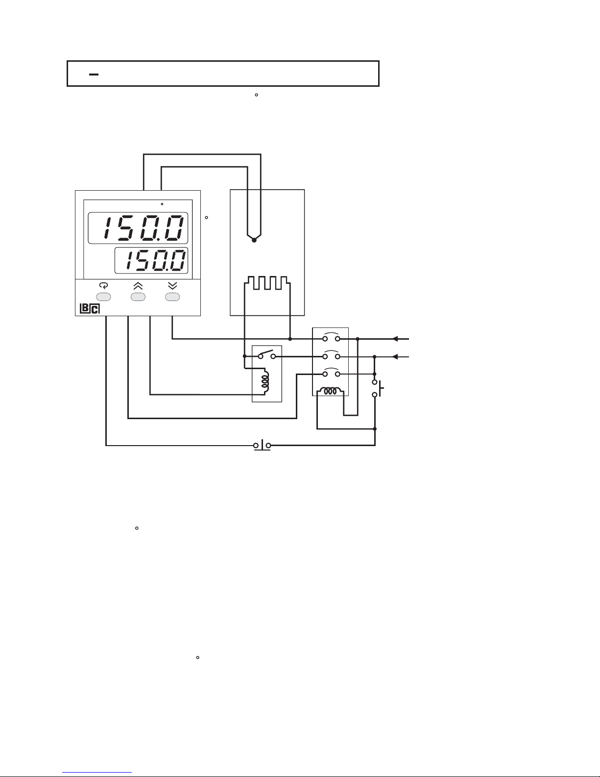
UM93001C
5 3 Heat Only Control5 3 Heat Only Control
An oven is designed to dry the products at 150 C for 30 minutes and then
stay unpowered for another batch. A BTC-9300 equipped with is
used for this purpose. The system diagram is shown as follows :
dwell timer
dwell timer
Heat Control ExampleHeat Control Example
Figure 5.5Figure 5.5
To achieve this function set the following parameters in the setup menu.To achieve this function set the following parameters in the setup menu.
Auto-Tuning is performed at 150 C for a new oven.Auto-Tuning is performed at 150 C for a new oven.
FUNC=BASC (Basic function )
IN1=K_TC
IN1U= C
DP1=1_DP
OUT1=REVR
O1TY=RELY
CYC1=18.0
O1FT=BPLS
A1FN=TIMR
A1FT=ON
SELF=NONE
FUNC=BASC (Basic function )
IN1=K_TC
IN1U=
C
DP1=1_DP
OUT1=REVR
O1TY=RELY
CYC1=18.0
O1FT=BPLS
A1FN=TIMR
A1FT=ON
SELF=NONE
A1 A2 PV
C
SV
OUT
BTC-9300
Mains
Supply
Mains
Supply
ON
OFF
Timer ( ALM1 )
Timer ( ALM1 )
Heater
T/C
Oven
5
6
78
OUT1
C
Set
SP1=150.0
TIME=30.0
SP1=150.0
TIME=30.0
86
Page 87

UM93001D
5 4 Cool Only Control5 4 Cool Only Control
A BTC-9300 is used to control a refrigerator at temperature below 0 C. To
avoid the set point adjustment beyond the interesting range, SP1L is set at 10 C and SP1H is set at 0 C. The temperature is lower than the ambient, a
cooling action is required. Hence select DIRT for OUT1. Since output 1 is used
to drive a magnetic contactor, O1TY selects RELY. A small temperature
oscillation is tolerable, hence use ON-OFF control to reduce the over-all cost.
To achieve ON-OFF control, PB1 is set with zero and O1HY is set at 0.1 C.
B
BB
B
A BTC-9300 is used to control a refrigerator at temperature below 0C.To
avoid
the set point adjustment beyond the interesting range, SP1L is set at -
10 C
and SP1H is set at 0C.The temperature is lower than the ambient, a
cooling
action is required. Hence select DIRT for OUT1. Since output 1 is used
to
drive a magnetic contactor, O1TY selects RELY. A small temperature
oscillation
is tolerable, hence use ON-OFF control to reduce the over-all cost.
To
achieve ON-OFF control, PB1 is set with zero and O1HY is set at 0.1 C.
B
BB
B
Setup Summary:Setup Summary:
FUNC=BASC
IN1=PT.DN
IN1U= C
DP1=1-DP
OUT1=DIRT
O1TY=RELY
SP1L=-10 C
SP1H= 0 C
FUNC=BASC
IN1=PT.DN
IN1U=
C
DP1=1-DP
OUT1=DIRT
O1TY=RELY
SP1L=-10
C
SP1H=
0 C
User Menu:User Menu:
PB1=0 ( C )
O1HY=0.1 ( C )
PB1=0 ( C )
O1HY=0.1
( C )
Cooling Control ExampleCooling Control Example
A1 A2 PV
C
SV
OUT
BTC-9300
Figure 5.6Figure 5.6
RTD
Refrigerator
11 12
13
5
6
Mains
Supply
Mains
Supply
87
ON-OFF control
Direct Control Action
ON-OFF control
Direct
Control Action
Page 88
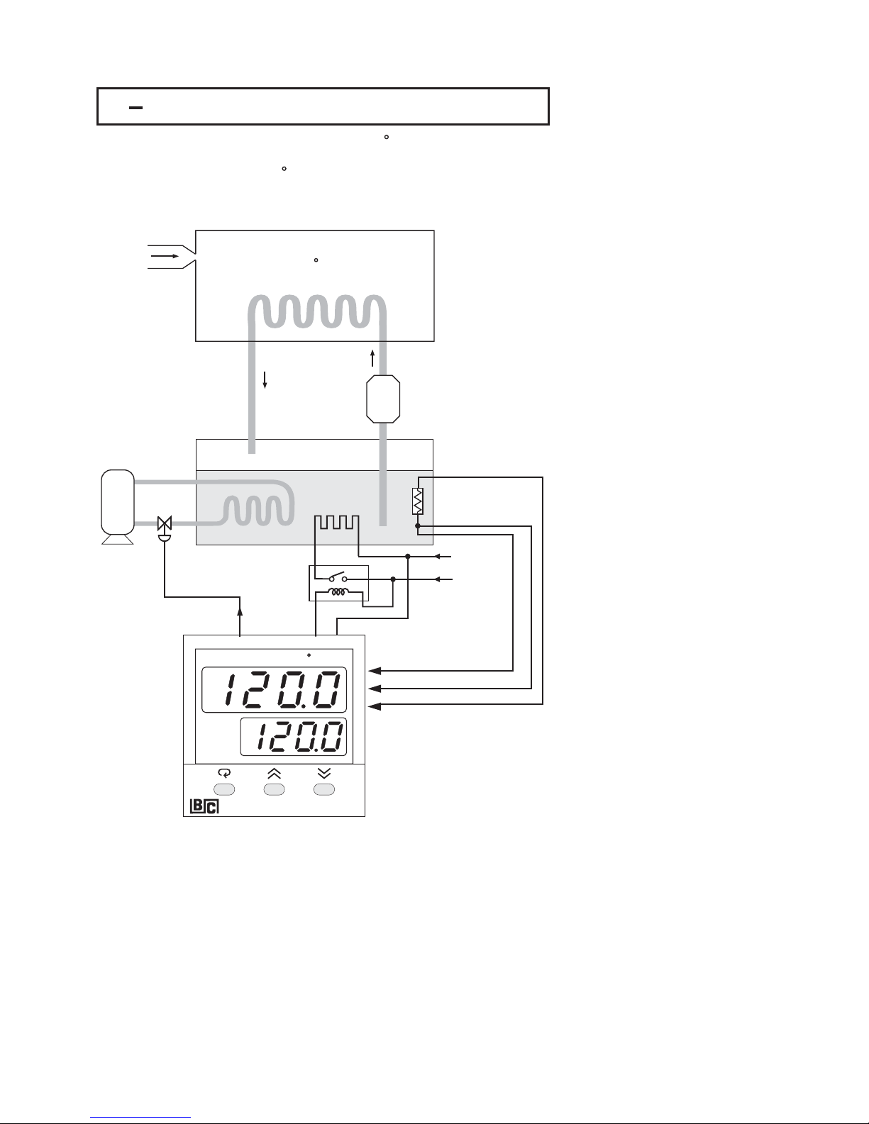
UM93001C
5 5 Heat-Cool Control5 5 Heat-Cool Control
An injection mold required to be controlled at 120 C to ensure a consistent
quality for the parts. An oil pipe is buried in the mold. Since plastics is injected
at higher temperature ( e.g. 250 C ), the circulation oil needs to be cooled as
its temperature rises. Here is an example:
An injection mold required to be controlled at 120 C to ensure a consistent
quality
for the parts. An oil pipe is buried in the mold. Since plastics is injected
at
higher temperature ( e.g. 250 C ), the circulation oil needs to be cooled as
its
temperature rises. Here is an example:
Plastics
Oil
Pump
Oil
Pump
Oil TankOil Tank
A1 A2 PV
C
SV
OUT
BTC-9300
Heater
Supply
Heater
Supply
Freezer
4-20 mA4-20 mA
OUT2
RTD
OUT1
IN1
Figure 5.7Figure 5.7
Heat-Cool Control ExampleHeat-Cool Control Example
Injection Mold
120 C
Injection Mold
120
C
88
Page 89

UM93001D
89
The PID Heat-Cool is used for the above example.
To achieve this set the following parameters in the Setup Menu:
The PID Heat-Cool is used for the above example.
To
achieve this set the following parameters in the Setup Menu:
Adjustment of CPB is related to the cooling media used. If water is used as
cooling media instead of oil, the CPB is set at 250 (%). If air is used as cooling
media instead of oil, the CPB is set at 100 (%).
Adjustment of DB is dependent on the system requirements. More positive
value of DB will prevent unwanted cooling action, but will increase the
temperature overshoot. while more negative value of DB will achieve less
temperature overshoot, but will increase unwanted cooling action.
Adjustment of CPB is related to the cooling media used. If water is used as
cooling
media instead of oil, the CPB is set at 250 (%). If air is used as cooling
media
instead of oil, the CPB is set at 100 (%).
Adjustment
of DB is dependent on the system requirements. More positive
value
of DB will prevent unwanted cooling action, but will increase the
temperature
overshoot. while more negative value of DB will achieve less
temperature
overshoot, but will increase unwanted cooling action.
FUNC=BASC
IN1=PT.DN
IN1U= C
DP1=1-DP
OUT1=REVR
O1TY=RELY
CYC1=18.0 (sec )
O1FT=BPLS
OUT2=COOL
O2TY=4-20
O2FT=BPLS
SELF=STAR
FUNC=BASC
IN1=PT.DN
IN1U=
C
DP1=1-DP
OUT1=REVR
O1TY=RELY
CYC1=18.0
(sec )
O1FT=BPLS
OUT2=COOL
O2TY=4-20
O2FT=BPLS
SELF=STAR
Adjust SP1 at 120.0 C , CPB at 125(%)andDBat-4.0 (%).Adjust SP1 at 120.0 C , CPB at 125 ( % ) and DB at -4.0 (%).
Apply at 120 C for a new system to get an optimal PID values.
See .
Auto-tuning
Section 3-19
Apply at 120 C for a new system to get an optimal PID values.
See .
Auto-tuning
Section
3-19
Key MenuKey Menu
FUNC
IN1
IN1U
DP1
OUT1
O1TY
CYC1
O1FT
OUT2
O2TY
O2FT
SELF
SP1
CPB
DB
FUNC
IN1
IN1U
DP1
OUT1
O1TY
CYC1
O1FT
OUT2
O2TY
O2FT
SELF
SP1
CPB
DB
Page 90

UM93001C
5 6 Ramp&Dwell5 6 Ramp & Dwell
Example 1: Temperature cycling ChamberExample 1: Temperature cycling Chamber
EIFN=SP.P2
A1FN=TIMR
OUT1=REVR, Relay Output
OUT2=COOL, 4-20mA Output
SPMD=MINR
IN1U= C
DP1=1-DP
EIFN=SP.P2
A1FN=TIMR
OUT1=REVR,
Relay Output
OUT2=COOL,
4-20mA Output
SPMD=MINR
IN1U=
C
DP1=1-DP
The circuit diagram and its temperature profile are shown below:The circuit diagram and its temperature profile are shown below:
A chamber is used to test the temperature cycling effect on the personal
computers. An external cycle timer is used to control the event input for
switching the set point. The products under test are required to stay at 60 C
for 1 hour and -10 C for 30 minutes. The transition interval between high-low
temperature is required to be 5 minutes. Make the following setup:
A chamber is used to test the temperature cycling effect on the personal
computers.
An external cycle timer is used to control the event input for
switching
the set point. The products under test are required to stay at 60 C
for
1 hour and -10 C for 30 minutes. The transition interval between high-low
temperature
is required to be 5 minutes. Make the following setup:
192
10
3114
12
5
13
6147158
16
BTC-9300
Freezer
Heater
Inverter
ON
OFF
65
35
Cycle TimerCycle Timer
AC RelayAC Relay
1
Mains
1
Mains
3AC3 AC
+
RTD
Chamber
TIME=60.0 (minutes )
SP1=60.0 C
SP2=-10.0 C
CPB=100 (%)
RAMP=14.0 ( C/minute )
TIME=60.0 (minutes )
SP1=60.0
C
SP2=-10.0
C
CPB=100
(%)
RAMP=14.0
( C/minute )
Figure 5.8Figure 5.8
A Temperature Cycling ChamberA Temperature Cycling Chamber
90
Page 91

UM93001C
60 minutes60 minutes 60 minutes60 minutes
60 C60 C 60 C60 C
5 minutes5 minutes
30
minutes
30
minutes
35
minutes
35
minutes
65 minutes65 minutes
-10 C-10 C -10 C-10 C
Figure 5.9Figure 5.9
Temperature Profile
of Chamber
Temperature Profile
of
Chamber
Example 2: Programmable Bread Baking OvenExample 2: Programmable Bread Baking Oven
Bread is baked in batches. A ramp is incorporated to control the thermal
gradient to suit for making the bread. A dwell timer is used to shut off the oven
power and announce the baker. The system is configured as shown in the
following diagram.
Bread is baked in batches. A ramp is incorporated to control the thermal
gradient
to suit for making the bread. A dwell timer is used to shut off the oven
power
and announce the baker. The system is configured as shown in the
following
diagram.
Figure 5.10Figure 5.10
A Bread Baking OvenA Bread Baking Oven
+
+
192
10
3114
12
5
13
6147
15
BTC-9300
8
16
AC RelayAC Relay
OFF
ON
220VAC
Mains
220VAC
Mains
Heater
Heater
Baking
Oven
Baking
Oven
Terminal 7 , 8 use
Form B Relay
Terminal 7 , 8 use
Form
B Relay
Order a form B relay for Alarm 1. Push ON switch to start a batch. The
temperature will rise with a ramp rate determined by RAMP value. Bread is
baked with the set point temperature for a definite time which is programmed
by TIME value, and then the power is shut off. The temperature profile is
shown in the following Figure.
Order a form B relay for Alarm 1. Push ON switch to start a batch. The
temperature
will rise with a ramp rate determined by RAMP value. Bread is
baked
with the set point temperature for a definite time which is programmed
by
TIME value, and then the power is shut off. The temperature profile is
shown
in the following Figure.
BTC-9300 provides 4-20 mA signal to control the speed of the Inverter.SP.P2
being chosen for EIFN is for the purpose of accomplishing a dual PID control.
You can perform auto-tuning twice at SP1 and SP2 for initial setup to the dual
PID values. Refer and .Sections 3-19 4-3
BTC-9300 provides 4-20 mA signal to control the speed of the Inverter.SP.P2
being
chosen for EIFN is for the purpose of accomplishing a dual PID control.
You
can perform auto-tuning twice at SP1 and SP2 for initial setup to the dual
PID
values. Refer and .Sections 3-19 4-3
40
minutes
40
minutes
40
minutes
40
minutes
180 C180 C
180 C180 C
Cooling
down
Cooling
down
Restart a
new batch
Restart a
new
batch
30 C/min30 C/min
PV
30 C30 C
5
45
Time
( minutes )
Time
(
minutes )
A1FN=TIMR
SPMD=MINR
Time=40.0 ( minutes )
RAMP=30.0 ( C/min )
Alarm 1: Form B Relay
A1FN=TIMR
SPMD=MINR
Time=40.0
( minutes )
RAMP=30.0
( C/min )
Alarm
1: Form B Relay
Figure 5.11Figure 5.11
Temperature Profile
of Baking Oven
Temperature Profile
of
Baking Oven
91
Page 92

5 7 Remote Set Point5 7 Remote Set Point
UM93001C
An on-line multiple zone oven is used to dry paint. Since heat demand is
various at different position in the production line, multiple zones with
individual controls should be used to ensure a consistent temperature profile.
If you order a BTC-9300 with a retransmission unit for the master controller,
and retransmit its set point to the input 2 of the rest of slave controllers, each
zone will be synchronized with the same temperature. Here is an example:
An on-line multiple zone oven is used to dry paint. Since heat demand is
various
at different position in the production line, multiple zones with
individual
controls should be used to ensure a consistent temperature profile.
If
you order a BTC-9300 with a retransmission unit for the master controller,
and
retransmit its set point to the input 2 of the rest of slave controllers, each
zone
will be synchronized with the same temperature. Here is an example:
A1 A2 PV
C
SV
OUT
BTC-9300
A1 A2 PV
C
SV
OUT
BTC-9300
A1 A2 PV
C
SV
OUT
BTC-9300
A1 A2 PV
C
SV
OUT
BTC-9300
To Control
Zone 1 Heater
To Control
Zone
1 Heater
To Control
Zone 2 Heater
To Control
Zone
2 Heater
To Control
Zone 3 Heater
To Control
Zone
3 Heater
To Control
Zone 4 Heater
To Control
Zone
4 Heater
Master
Slave Slave Slave
10 9 15 15 15
16 16 16
+ + + +
Figure 5.12Figure 5.12
Remote Set Point
Application
Remote Set Point
Application
Set the following parameters in the setup menu:Set the following parameters in the setup menu:
Note: AOHI and IN2H should be set with values higher than the set point range used.Note: AOHI and IN2H should be set with values higher than the set point range used.
For master unit
FUNC= FULL
COMM= 1 5 V
AOLO= 0 C
AOHI = 300 C
PVMD= PV1
SPMD= SP1.2
For master unit
FUNC=
FULL
COMM=
1 5 V
AOLO=
0 C
AOHI
= 300 C
PVMD=
PV1
SPMD=
SP1.2
92
OUT1 OUT1 OUT1 OUT1
For slave units
FUNC= FULL
IN2= 1 5 V
IN2L= 0 C
IN2H= 300 C
PVMD= PV1
SPMD= PV2
For slave units
FUNC=
FULL
IN2=
1 5 V
IN2L=
0 C
IN2H=
300 C
PVMD=
PV1
SPMD=
PV2
If a voltage signal (such as the above example) is sent to slave units, the slave
inputs are connected in parallel. If a current signal (e.g. 4-20 mA) is sent to
slave units, the slave inputs should be connected in series. The current
retransmission is used widely since it can transmit to a longer distance without
voltage drop.
If a voltage signal (such as the above example) is sent to slave units, the slave
inputs
are connected in parallel. If a current signal (e.g. 4-20 mA) is sent to
slave
units, the slave inputs should be connected in series. The current
retransmission
is used widely since it can transmit to a longer distance without
voltage
drop.
Page 93

UM93001C
5 8 Differential Control5 8 Differential Control
In certain applications it is desirable to control a second process such that its
process value always deviates from the first process with a constant value.
Water tank 1 is 5.12 meters height and water tank 2 level is desirable to be
maintained at 1 meter lower than tank 1 level.
In certain applications it is desirable to control a second process such that its
process
value always deviates from the first process with a constant value.
Water
tank 1 is 5.12 meters height and water tank 2 level is desirable to be
maintained
at 1 meter lower than tank 1 level.
Set the following parameters in the setup menu:
FUNC= FULL
IN1, IN1L, IN1H : According to Sensor 1 signal
IN1U= PU
DP1= 2-DP
IN2, IN2L, IN2H : According to Sensor 2 signal
IN2U= PU
DP2= 2-DP
OUT1= REVR
O1TY= 4 20
PVMD= P1-2
SPMD=SP1.2
FUNC= FULL
IN1,
IN1L, IN1H : According to Sensor 1 signal
IN1U=
PU
DP1=
2-DP
IN2,
IN2L, IN2H : According to Sensor 2 signal
IN2U=
PU
DP2=
2-DP
OUT1=
REVR
O1TY=
4 20
PVMD=
P1-2
SPMD=SP1.2
A1 A2 PV
SV
OUT
BTC-9300
Outlet
Outlet
From Controller Output
From Controller Output
4-20 mA Valve Control Output4-20 mA Valve Control Output
Water Tank 1Water Tank 1
Water Tank 2Water Tank 2
Level Sensor 1Level Sensor 1
Level Sensor 2Level Sensor 2
5.12 M Height5.12 M Height
4.12 M Height4.12 M Height
IN1 IN2
SV=1.00
PV=1.00
PV1=5.12
PV2=4.12
SV=1.00
PV=1.00
PV1=5.12
PV2=4.12
OUT1
Figure 5.13Figure 5.13
Differential Control ExampleDifferential Control Example
Adjust SP1( here is 1.00 ) to control the difference between PV1 and PV2.
Choosing P1-2 for PVMD, the PV display will show the difference value ( PV1PV2 ) between PV1 and PV2, and this value will be stabilized to the set point (
here is 1.00 ).
If you need PV1 or PV2 instead of PV, you can use the Display Mode to select
PV1 or PV2 to be displayed. See . The above diagram indicates
PV2 instead of PV.
Section 3-23
Adjust SP1( here is 1.00 ) to control the difference between PV1 and PV2.
Choosing
P1-2 for PVMD, the PV display will show the difference value ( PV1-
PV2
) between PV1 and PV2, and this value will be stabilized to the set point (
here
is 1.00 ).
If
you need PV1 or PV2 instead of PV, you can use the Display Mode to select
PV1
or PV2 to be displayed. See . The above diagram indicates
PV2
instead of PV.
Section
3-23
93
Page 94

UM93001C
5 9 Dual Set Point / PID5 9 Dual Set Point / PID
The BTC-9300 will switch between the two PID sets based on the process
value, the set point or either of the event input. As the control ramps up to the
higher process value, the process characteristics changes. As this happens,
the original PID values are no longer valid. To achieve optimal control over the
entire range, a second PID set is used.
The BTC-9300 will switch between the two PID sets based on the process
value,
the set point or either of the event input. As the control ramps up to the
higher
process value, the process characteristics changes. As this happens,
the
original PID values are no longer valid. To achieve optimal control over the
entire
range, a second PID set is used.
Example 1: Single Set Point / Dual PIDExample 1: Single Set Point / Dual PID
A heat treating furnace is used over the range of 400 C to 1200 C.A heat treating furnace is used over the range of 400 C to 1200 C.
( 1 ) Set the following parameters in the Setup menu:( 1 ) Set the following parameters in the Setup menu:
FUNC= FULL
A1FN= PV1H
A1MD= NORM
EIFN= PID2
PVMD= PV1
SPMD= MINR
FUNC= FULL
A1FN=
PV1H
A1MD=
NORM
EIFN=
PID2
PVMD=
PV1
SPMD=
MINR
( 2 ) Adjust the following parameters in the User menu:( 2 ) Adjust the following parameters in the User menu:
A1SP= 800 C
A1HY= 1.0 C
PL1= 100(%)
RAMP: According to the process requirement
SP1: According to the process requirement
A1SP= 800 C
A1HY=
1.0 C
PL1=
100 ( % )
RAMP:
According to the process requirement
SP1:
According to the process requirement
( 3 ) Tune first PID set at SP1= 500 C and tune second PID set at SP1=1100 C,
or set the proper values for PB1, TI1, TD1, PB2, TI2 and TD2 directly
according to the previous records to eliminate auto-tuning sequence.
( 3 ) Tune first PID set at SP1= 500 C and tune second PID set at SP1=1100 C,
or
set the proper values for PB1, TI1, TD1, PB2, TI2 and TD2 directly
according
to the previous records to eliminate auto-tuning sequence.
The circuit diagram and its temperature profile are shown as follows :The circuit diagram and its temperature profile are shown as follows :
192
10
3114
12
5
13
6147158
16
To
Furnace
Heater
To
Furnace
Heater
Heater
Power
Input
Heater
Power
Input
AC powerAC power
Alarm 1 controls
Event input
Alarm 1 controls
Event
input
Figure 5.14Figure 5.14
Dual PID FurnaceDual PID Furnace
Process ValueProcess Value
PID Crossover ValuePID Crossover Value
Use PID 1Use PID 1
Use PID 2Use PID 2
Time
C
800
Figure 5.15Figure 5.15
Dual PID CrossoverDual PID Crossover
94
Page 95
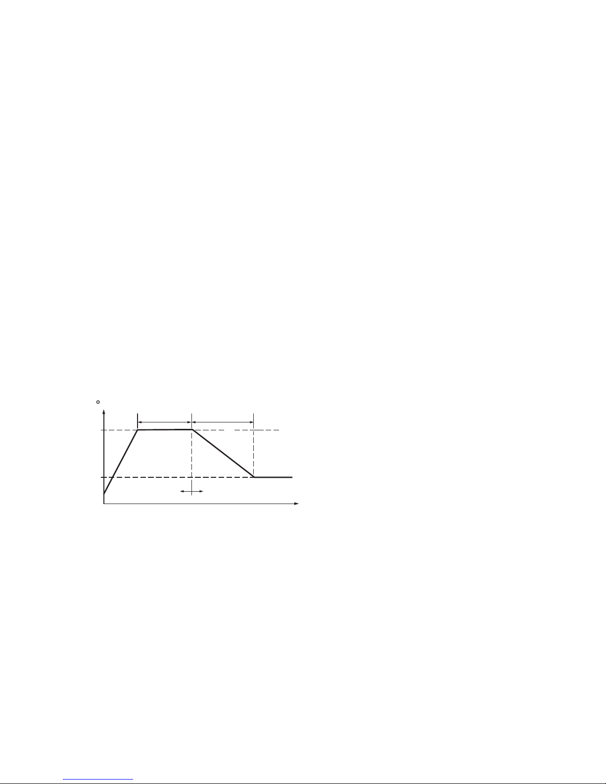
UM93001C
A heat treating furnace is required to harden the mold at a high temperature (
1000 C ) for 30 minutes, then the mold is cooled down with a programmable
ramp ( 20 C / minute ) toward a lower set point ( 200 C ). Use the dual set
point / PID and ramp / dwell functions for this application.
L
LL
A heat treating furnace is required to harden the mold at a high temperature (
1000 C
) for 30 minutes, then the mold is cooled down with a programmable
ramp
( 20 C / minute ) toward a lower set point ( 200 C ). Use the dual set
point
/ PID and ramp / dwell functions for this application.
L
LL
Example 2: Dual Set Point / PIDExample 2: Dual Set Point / PID
( 1 ) Set the following parameters in the Setup menu:( 1 ) Set the following parameters in the Setup menu:
FUNC= FULL
A1FN= TIMR
EIFN= SP.P2
PVMD= PV1
SPMD= MINR
FUNC= FULL
A1FN=
TIMR
EIFN=
SP.P2
PVMD=
PV1
SPMD=
MINR
( 2 ) Adjust the following parameters in the User menu:( 2 ) Adjust the following parameters in the User menu:
TIME= 30.0 ( Minutes )
RAMP= 20.0 ( C/Minute )
SP1= 1000 C
SP2= 200 C
PL1= 100(%)
L
L
L
TIME= 30.0 ( Minutes )
RAMP=
20.0 ( C/Minute )
SP1=
1000 C
SP2=
200 C
PL1=
100 ( % )
L
L
L
( 3 ) Set the proper values for PB1, TI1, TD1,PB2, TI2 and TD2 directly according
to the previous records. For a new system tune first PID set at SP1=800 C
and tune second PID set at SP2=400 C.LL
( 3 ) Set the proper values for PB1, TI1, TD1,PB2, TI2 and TD2 directly according
to
the previous records. For a new system tune first PID set at SP1=800 C
and
tune second PID set at SP2=400 C.LL
The circuit diagram is same as shown in Figure 5.14. The temperature profile
is shown as below:
The circuit diagram is same as shown in Figure 5.14. The temperature profile
is
shown as below:
Figure 5.16Figure 5.16
Dual Set Point /PID ProfileDual Set Point /PID Profile
30
minutes
30
minutes
40
minutes
40
minutes
1000
200
Use SP1,PID1
Use SP1,PID1 Use SP2,PID2Use SP2,PID2
C
Time ( Minutes )Time ( Minutes )
95
Page 96

UM93001C
5 10 RS-4855 10 RS-485
A making plant has 5 production lines. Each production line is equipped
with 16 units of BTC-9300 to control the temperature for the . They are
desirable to program the controllers and monitor the process in the control
room for the purpose of improving the quality and productivity. A cost effective
solution for the above application is to use 80 units of plus
a and PC based software for this
purpose.
tile
kiln
BTC-9300-XXXXX1
SNA10B Smart Network Adaptor BC-Net
A making plant has 5 production lines. Each production line is equipped
with
16 units of BTC-9300 to control the temperature for the . They are
desirable
to program the controllers and monitor the process in the control
room
for the purpose of improving the quality and productivity. A cost effective
solution
for the above application is to use 80 units of plus
a and PC
based software for this
purpose.
tile
kiln
BTC-9300-XXXXX1
SNA10B Smart Network Adaptor BC-Net
The system is installed as shown in the following diagram.The system is installed as shown in the following diagram.
A1 A2 PV
C
F
SV
OUT
BTC-9300
A1 A2 PV
C
F
SV
OUT
BTC-9300
A1 A2 PV
C
F
SV
OUT
BTC-9300
A1 A2 PV
C
F
SV
OUT
BTC-9300
A1 A2 PV
C
F
SV
OUT
BTC-9300
A1 A2 PV
C
F
SV
OUT
BTC-9300
Kiln 1Kiln 1
Kiln 5Kiln 5
Kiln 2Kiln 2
Kiln 3Kiln 3
Kiln 4Kiln 4
TX1
TX1
TX1
TX1 TX1
TX1 TX1
TX1
TX1
TX2
TX2
TX2
TX2 TX2
TX2 TX2
TX2
TX2
1
65
2
66
16
80
Control RoomControl Room
PC
(BC-Net)
PC
(
BC-Net )
RS-232
SNA10B
TX1TX2
Twisted-pair wire, max. distance 1 KmTwisted-pair wire, max. distance 1 Km
Figure 5.17Figure 5.17
RS-485 ApplicationsRS-485 Applications
96
Terminator, 220 ohms/0.5WTerminator, 220 ohms/0.5W
Page 97

UM93001C
Enters the setup mode to configure each BTC-9300. Choose FULL for FUNC,
485 for COMM, RTU for PROT and select an unequal address ( ADDR ) for each
unit. Use the same values of BAUD, DATA, PARI and STOP for BTC-9300's,
SNA10B and BC-Net. Also refer to and .Section 2-15 Section 4-8
Enters the setup mode to configure each BTC-9300. Choose FULL for FUNC,
485
for COMM, RTU for PROT and select an unequal address ( ADDR ) for each
unit.
Use the same values of BAUD, DATA, PARI and STOP for BTC-9300's,
SNA10B
and BC-Net. Also refer to and .Section 2-15 Section 4-8
Taking the advantage of BC-Net software, the operator can monitor the
process on the PC screen, program the set point as well as other control
parameters such as PID values, down load the ramp and soak profile to the
controllers, execute the manual control or trigger an auto-tuning.....etc. , and
print out a report as required. The historical data can be saved in the floppy
disc, hard disc or a CD for permanent storage purpose.
Taking the advantage of BC-Net software, the operator can monitor the
process
on the PC screen, program the set point as well as other control
parameters
such as PID values, down load the ramp and soak profile to the
controllers,
execute the manual control or trigger an auto-tuning.....etc. , and
print
out a report as required. The historical data can be saved in the floppy
disc,
hard disc or a CD for permanent storage purpose.
Setup Setup MenuSetup Menu
FUNC
COMM
PROT
ADDR
BAUD
DATA
PARI
STOP
FUNC
COMM
PROT
ADDR
BAUD
DATA
PARI
STOP
97
Page 98

UM93001C
5 11 RS-2325 11 RS-232
Suppose a chemical experiment is performed in a laboratory. And an engineer
desires to find out the relation between the chemical reaction and temperature.
He uses a BTC-9300 to control the temperature of the solution under test. A
testing report containing the relation between the concentration and
temperature is particularly interested.
Suppose a chemical experiment is performed in a laboratory. And an engineer
desires
to find out the relation between the chemical reaction and temperature.
He
uses a BTC-9300 to control the temperature of the solution under test. A
testing
report containing the relation between the concentration and
temperature
is particularly interested.
For a single unit application it is adequate to order a with
RS-232 communication and a software. By using the BC-Net software
the temperature data can be viewed and stored in a file. The user can
program the temperature as well as other control parameters such as PID
values. He can setup the controller, down load a ramp and soak profile, also
execute the manual control or auto-tuning procedure ..... etc. The results can
be printed out or stored in a file for the future reference.
BTC-9300-xxxxx2
BC-Net
For a single unit application it is adequate to order a with
RS-232
communication and a software. By using the BC-Net software
the
temperature data can be viewed and stored in a file. The user can
program
the temperature as well as other control parameters such as PID
values.
He can setup the controller, down load a ramp and soak profile, also
execute
the manual control or auto-tuning procedure ..... etc. The results can
be
printed out or stored in a file for the future reference.
BTC-9300-xxxxx2
BC-Net
Refer to for installation and for setup procedure.Section 2-16 Section 4-8Refer to for installation and for setup procedure.Section 2-16 Section 4-8
Setup MenuSetup Menu
FUNC
COMM
PROT
ADDR
BAUD
DATA
PARI
STOP
FUNC
COMM
PROT
ADDR
BAUD
DATA
PARI
STOP
98
Page 99

UM93001C
5 12 Retransmit5 12 Retransmit
An air-conditioned room uses two units of BTC-9300 to control its temperature
and humidity. The temperature and humidity are required to be recorded on a
chart recorder. The interesting ranges for these two quantity are: 20 C to 30 C
and 40% RH to 60% RH. The recorder inputs accept0-5Vsignal.
An air-conditioned room uses two units of BTC-9300 to control its temperature
and
humidity. The temperature and humidity are required to be recorded on a
chart
recorder. The interesting ranges for these two quantity are: 20 C to 30 C
and
40% RH to 60% RH. The recorder inputs accept 0 - 5 V signal.
To achieve this, set the following parameters in the Setup menu.To achieve this, set the following parameters in the Setup menu.
UNIT 1:UNIT 1: UNIT 2:UNIT 2:
FUNC= FULL
COMM=0-5V
AOFN=PV1
AOLO=20.0 ( C )
AOHI= 30.0 ( C )
IN1= PTDN
IN1U= C
DP1= 1-DP
FUNC= FULL
COMM=
0 - 5V
AOFN=PV1
AOLO=20.0
( C )
AOHI=
30.0 ( C )
IN1=
PTDN
IN1U=
C
DP1=
1-DP
FUNC= FULL
COMM=0-5V
AOFN=PV1
AOLO=40.0 ( % )
AOHI= 60.0 ( % )
IN1=0-1V(According to humidity sensor )
IN1U= PU
DP1= 1-DP
FUNC= FULL
COMM=
0 - 5V
AOFN=PV1
AOLO=40.0
( % )
AOHI=
60.0 ( % )
IN1=
0 - 1 V (According to humidity sensor )
IN1U=
PU
DP1=
1-DP
A1 A2 PV
C
SV
OUT
BTC-9300
A1 A2 PV
C
SV
OUT
BTC-9300
1. 20-30 C 2. 40-50%1. 20-30 C 2. 40-50%
Chart RecorderChart Recorder
0-5V0 - 5 V 0-5V0 - 5 V
+ +
Retransmission OutputRetransmission Output
9 910 10
C
%RH
SP1= 25.0
SP1L= 20.0
SP1H= 30.0
SP1= 25.0
SP1L=
20.0
SP1H=
30.0
SP1= 50.0
SP1L= 40.0
SP1H= 60.0
SP1= 50.0
SP1L=
40.0
SP1H=
60.0
Figure 5.18Figure 5.18
Retransmission ApplicationRetransmission Application
SP1L and SP1H are used to limit the adjustment range of set point.SP1L and SP1H are used to limit the adjustment range of set point.
99
Page 100

Chapter 6 CalibrationChapter 6 Calibration
Do not proceed through this section unless there is a definite need to
re-calibrate the controller. Otherwise, all previous calibration data will be
lost. Do not attempt recalibration unless you have appropriate calibration
equipment. If calibration data is lost, you will need to return the controller
to your supplier who may charge you a service fee to re-calibrate the
controller.
Do not proceed through this section unless there is a definite need to
re-calibrate
the controller. Otherwise, all previous calibration data will be
lost.
Do not attempt recalibration unless you have appropriate calibration
equipment.
If calibration data is lost, you will need to return the controller
to
your supplier who may charge you a service fee to re-calibrate the
controller.
Entering calibration mode will break the control loop. Make sure that if
the system is allowable to apply calibration mode.
Entering calibration mode will break the control loop. Make sure that if
the
system is allowable to apply calibration mode.
Equipments needed before calibration:Equipments needed before calibration:
(1) A high accuracy calibrator ( Fluke 5520A Calibrator recommended )
with following functions:
0 - 100 mV millivolt source with 0.005 % accuracy
0 - 10 V voltage source with 0.005 % accuracy
0 - 20 mA current source with 0.005 % accuracy
0 - 300 ohm resistant source with 0.005 % accuracy
(2) A test chamber providing 25 C - 50 C temperature range
(3) A switching network ( SW6400, optional for automatic calibration )
(4) A calibration fixture equipped with programming units ( optional for
automatic calibration )
(5) A PC installed with calibration software BC-Net and Smart Network
Adaptor SNA10B ( optional for automatic calibration )
A
A
A
A
BB
(1) A high accuracy calibrator ( Fluke 5520A Calibrator recommended )
with
following functions:
0
- 100 mV millivolt source with 0.005 % accuracy
0
- 10 V voltage source with 0.005 % accuracy
0
- 20 mA current source with 0.005 % accuracy
0
- 300 ohm resistant source with 0.005 % accuracy
(2)
A test chamber providing 25 C - 50 C temperature range
(3)
A
switching
network ( SW6400, optional for automatic calibration )
(4)
A calibration fixture equipped with programming units ( optional for
automatic
calibration )
(5)
A PC installed with calibration software BC-Net and Smart Network
Adaptor
SNA10B ( optional for automatic calibration )
A
A
A
A
BB
UM93001C
The calibration procedures described in the following section are a step by step
.manual procedures
The calibration procedures described in the following section are a step by step
.manual
procedures
Since it needs 30 minutes to warm up an unit before calibration, calibrating the
unit one by one is quite inefficient. An for small
quantity as well as for unlimited quantity is available upon request.
automatic calibration system
Since it needs 30 minutes to warm up an unit before calibration, calibrating the
unit
one by one is quite inefficient. An for small
quantity
as well as for unlimited quantity is available upon request.
automatic
calibration system
100
 Loading...