

Page 1
XC
Range Product
Manual
38
XC Range Product Manual
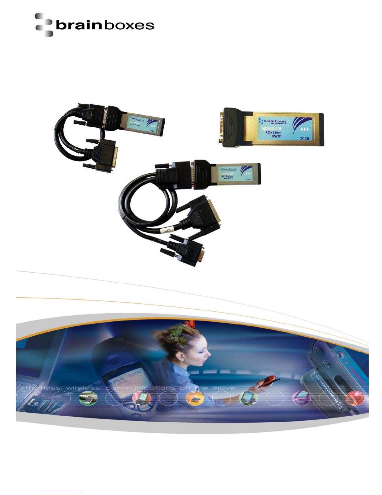
XC-157, XC-235 and XC-475
Print date: 02/04/2015
V1.0
© Copyright Brainboxes Ltd Page 1 of
Page 2

Print date: 02/04/2015
XC
Range Product
Manual
38
Contents
XC Range Product Manual ...................................................................................................................... 1
XC-157, XC-235 and XC-475 ................................................................................................................ 1
1. Introduction to the XC range .............................................................................................................. 4
2. Supported operating systems ............................................................................................................. 5
3. Installation Instructions ...................................................................................................................... 6
3.1 Windows XP and Windows Server 2003 installation .................................................................... 7
3.2 Windows Vista and Windows Server 2008 installation .............................................................. 10
3.3 Windows 7 and Windows Server 2008 R2 installation ............................................................... 13
3.4 Windows 8 installation................................................................................................................ 17
4. Product Configuration ....................................................................................................................... 20
4.1 Finding your Brainboxes COM port ............................................................................................. 20
4.2 Changing the COM label ............................................................................................................. 21
4.3 Changing the port settings .......................................................................................................... 21
5. RS-232 Information ........................................................................................................................... 24
5.1 The RS-232 Standard ................................................................................................................... 24
5.2 9 Pin D Serial Port RS-232 Cables ................................................................................................ 24
5.3 Pin D serial port connection to another PC ................................................................................ 24
6. LPT printer port information ............................................................................................................. 26
7. UART Settings .................................................................................................................................... 27
7.1 Receive Trigger Level .................................................................................................................. 28
7.2 Transmit Trigger Level ................................................................................................................. 28
7.3 Flow Control Trigger Level .......................................................................................................... 28
8. Uninstallation instructions ................................................................................................................ 30
8.1 Windows Server 2008/Vista/Server 2003/XP ............................................................................. 30
9. Boost.PCIe Driver Upgrade / Rollback............................................................................................... 32
9.1 Upgrading the Boost.PCIe Driver ................................................................................................ 32
10. Troubleshooting and Testing .......................................................................................................... 33
10.1 Installation problems ................................................................................................................ 33
10.2 Communication Problems......................................................................................................... 33
10.3 Testing your serial COM port .................................................................................................... 33
11. Lifetime warranty and support ....................................................................................................... 35
12. Technical specification .................................................................................................................... 36
12.1 Support serial settings .............................................................................................................. 36
V1.0
© Copyright Brainboxes Ltd Page 2 of
Page 3

Print date: 02/04/2015
XC
Range Product
Manual
38
12.2 RS-232 Pinout ............................................................................................................................ 36
12.3 LPT pinout ................................................................................................................................. 36
13. Regulatory Approvals / Compliance................................................................................................ 37
13.1 Company Accreditation......................................................................................................... 37
13.2 Europe – EU Declaration of Conformity ................................................................................ 37
13.3 WEEE Directive (Waste Electrical and Electronic Equipment) .............................................. 37
13.4 RoHS Compliance .................................................................................................................. 38
14. Copyright ................................................................................................................................... 38
V1.0
© Copyright Brainboxes Ltd Page 3 of
Page 4
Print date: 02/04/2015
XC
Range Product
Manual
38
1. Introduction to the XC range
Where absolute compatibility with classic desktop LPT parallel printer ports is a necessity, our XC
range really does excel. With guaranteed low latency, memory mapped, no compromise high
performance interface, there is no better option. Drivers for available for Windows 32 bit and 64 bit
Operating Systems including Windows XP, Server 2003, Vista, Server 2008, Windows 7 and Windows
8.
Unlike the VX range which uses USB technology over ExpressCard; this uses PCI Express technology
over ExpressCard. All Brainboxes XC cards are PCI Express Base Specification 1.1 Compliant.
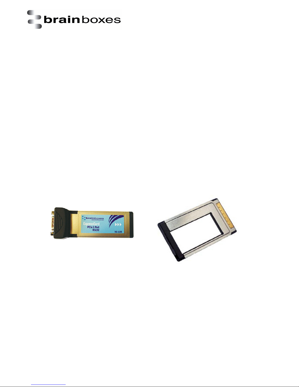
ExpressCards are the new connect standard for laptops and can be found in most laptops supplied
since 2006/07. ExpressCard slots come in 34mm and 54mm widths, all of Brainboxes ExpressCards
will fit in either slot. Use our ExpressCard spacer in 54mm slots when you require added physical
security.
The cards are hot swappable and can be added or removed without having to turn your PC on or off.
The ExpressCard standard define two form factors, the 34mm wide ExpressCard/34 and the 54mm
wide ExpressCard/54.
Whilst the 34mm slot accepts only 34mm cards the 54mm slot accepts both 34mm and 54mm cards.
Brainboxes ExpressCard range being 34mm wide will fit into any ExpressCard slot on your laptop
computer. For a more secure connection into a 54mm slot a Brainboxes VX-056 ExpressCard
spacer can be purchased in conjunction with the card.
V1.0
© Copyright Brainboxes Ltd Page 4 of
Page 5
Print date: 02/04/2015
XC
Range Product
Manual
38
2. Supported operating systems
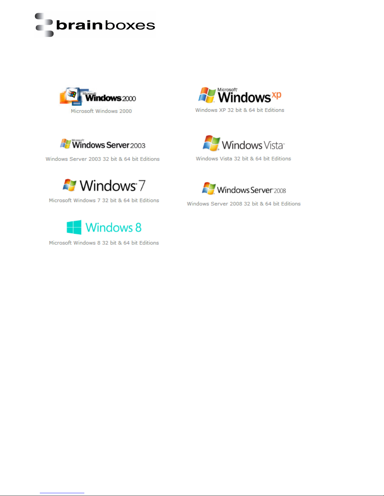
The PCI Express XC Range can be used with the following Microsoft Operating Systems with the
supplied Boost.PCIe drivers:
Brainboxes PCI Express Drivers have undergone Microsoft testing with the XC RS-232 and LPT printer
port family. Upon passing these tests, the drivers were signed by Microsoft, as an indication of their
quality and stability.
V1.0
© Copyright Brainboxes Ltd Page 5 of
Page 6
Print date: 02/04/2015
XC
Range Product
Manual
38
3. Installation Instructions
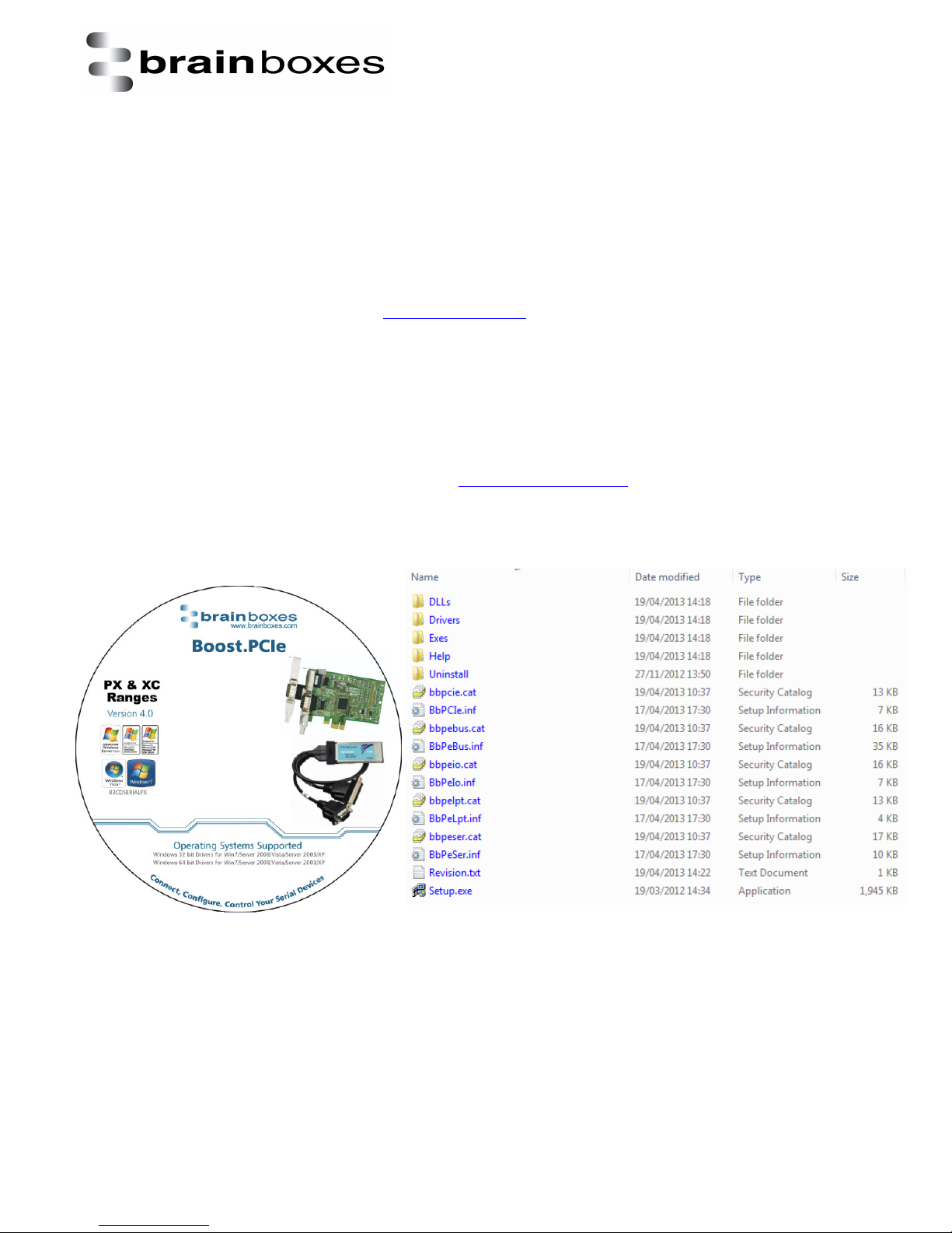
To install the XC-157, XC-235 or XC-475, simply follow the step-by-step guide below.
• Insert your PCI ExpressCard in to a free ExpressCard slot.
• Insert your XC CD.
• Windows will detect the new hardware; follow the Found New Hardware Wizard prompts to
install the driver from the correct location on the CD ROM.
• Alternatively, run the setup.exe file found in the root of the CD ROM.
If you are downloading drivers from www.brainboxes.com please follow the steps below to install
the XC drivers.
• Unzip the driver folder.
• Uninstall any current XC driver software by using the BbPUn43.exe in the Exe’s folder.
• Now go back to the main folder and select the setup.exe file.
• Click next and the device will install.
If any of the above fail to work, please contact [email protected] and we will assist you
with product installation.
V1.0
© Copyright Brainboxes Ltd Page 6 of
Page 7
Print date: 02/04/2015
XC
Range Product
Manual
38
3.1 Windows XP and Windows Server 2003 installation
The literature below shows an XC-235 device in XP and Server 2003 as an example. The same
installation steps can be applied to all other products in the XC range.
1. Insert the XC CD in to your laptop.
2. Insert the XC-235 in to an available ExpressCard slot on your laptop.
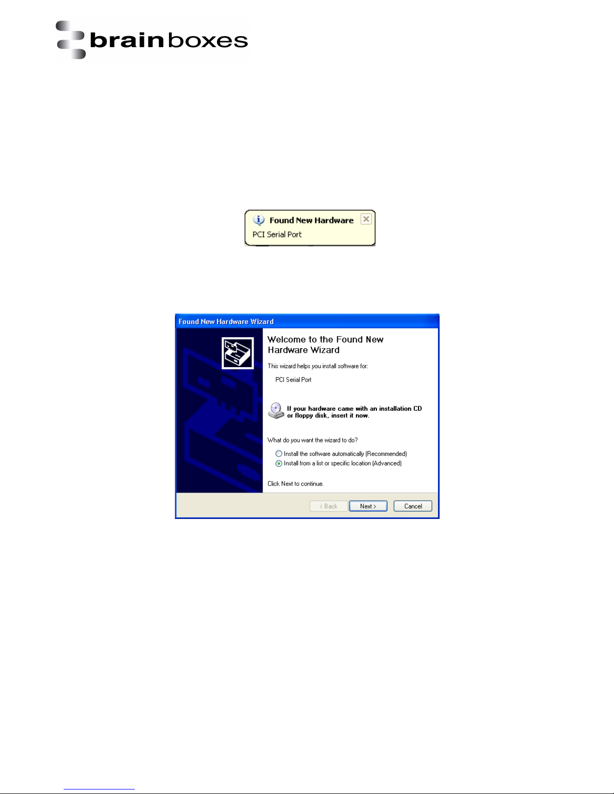
3. You will now see the below hardware wizard prompt, click on it.
4. You will now see the below window appear; select the ‘Install from a list or specific location
(Advanced) option.
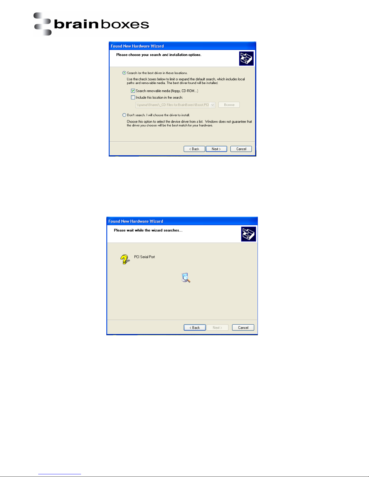
5. Now select the ‘Search removable media (floppy, CD-ROM…)’ option as shown below.
V1.0
© Copyright Brainboxes Ltd Page 7 of
Page 8
Print date: 02/04/2015
XC
Range Product
Manual
38
6. Your laptop will now start to scan the CD-ROM and you will now see a window like this:
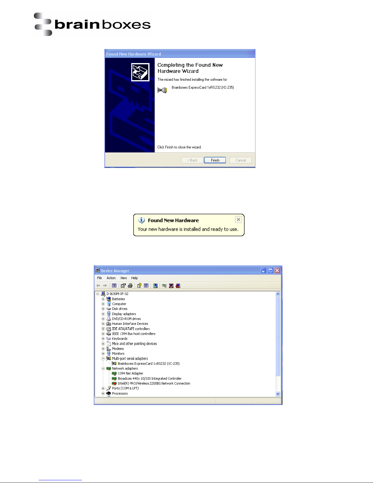
7. After the CD-ROM has been scanned for the XC drivers, you will now see a window telling
you that the driver installation has finished. It looks like this:
V1.0
© Copyright Brainboxes Ltd Page 8 of
Page 9
Print date: 02/04/2015
XC
Range Product
Manual
38
8. Now that the installation has finished, you will see one final hardware wizard prompt which
tells you that your hardware is now ready to be used.
9. In device manager, you can now see your XC-235 installed. It should look like this:
V1.0
© Copyright Brainboxes Ltd Page 9 of
Page 10
Print date: 02/04/2015
XC
Range Product
Manual
38
3.2 Windows Vista and Windows Server 2008 installation
The literature below shows an XC-235 device in Vista and Windows Server 2008 as an example. The
same installation steps can be applied to all other products in the XC range.
1. Insert the XC CD in to your laptop.
2. Insert the XC-235 in to an available ExpressCard slot on your laptop.
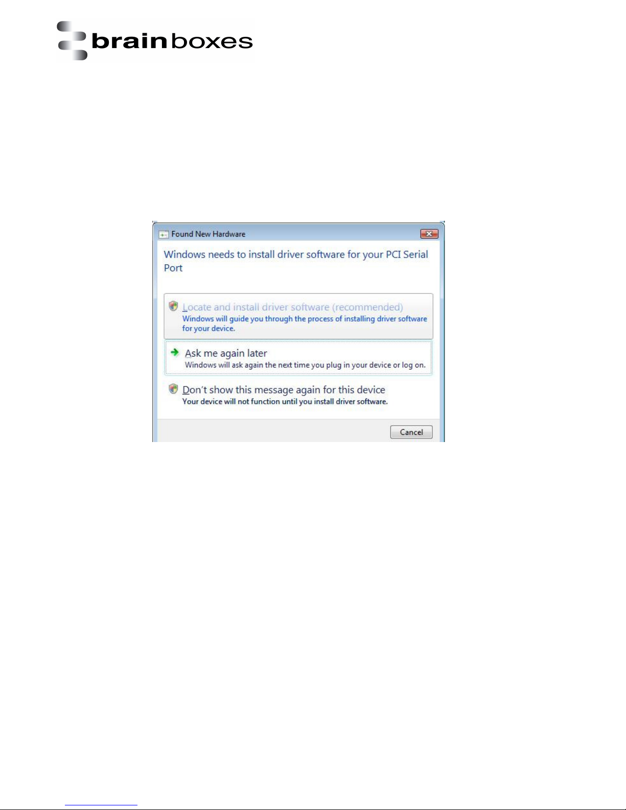
3. The Found New Hardware Wizard will come up. If your computer is set to check Windows
Update Automatically for a driver, then it could take longer for this screen to pop up.
4. Select ‘Locate and install driver software’.
5. NB - Vista will enter the Security Check to ensure that you have initiated the installation (and
not some malicious program). Click Continue
V1.0
© Copyright Brainboxes Ltd Page 10 of
Page 11
Print date: 02/04/2015
XC
Range Product
Manual
38
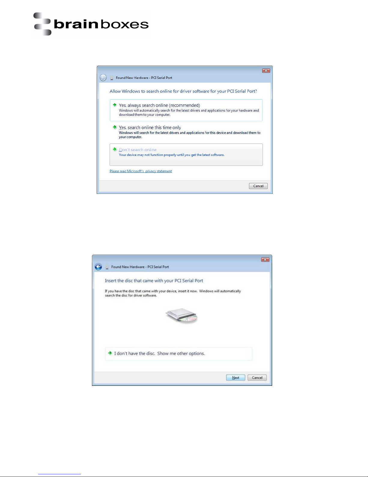
6. If you would like to install via Windows Update, select “Yes, this time only”. This will take
you to Step 9. Otherwise select ‘Don’t search online’ to install from the CD.
7. The Found New Hardware Wizard will then ask you to locate the software drivers. Ensure
that the CD is in the drive and click Next
V1.0
© Copyright Brainboxes Ltd Page 11 of
Page 12
XC
Range Product
Manual
38
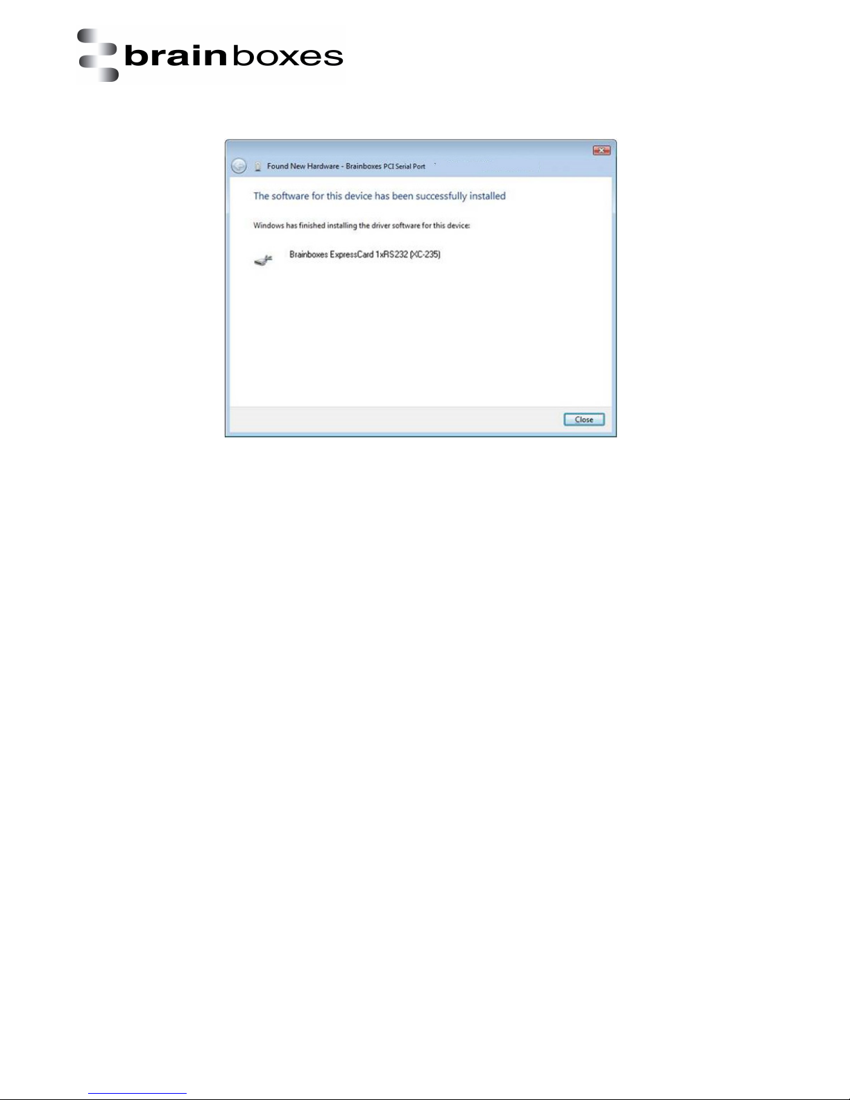
8. Once the driver has been installed, click Close.
Print date: 02/04/2015
V1.0
© Copyright Brainboxes Ltd Page 12 of
Page 13
Print date: 02/04/2015
XC
Range Product
Manual
38
3.3 Windows 7 and Windows Server 2008 R2 installation
The literature below shows an XC-235 device in Windows 7 and Windows Server 2008 R2 as an
example. The same installation steps can be applied to all other products in the XC range.
1. Insert the XC CD in to your laptop.
2. Insert the XC-235 in to an available ExpressCard slot on your laptop.
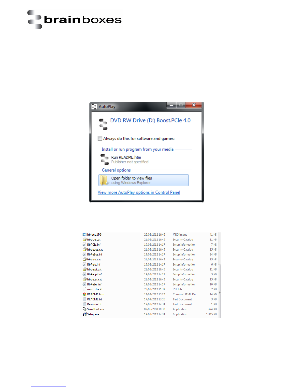
3. You will now see the below window appear. Click on the ‘Open folder to view files’ option.
4. Scroll down to the bottom of the list of files and select the setup.exe file as shown below.
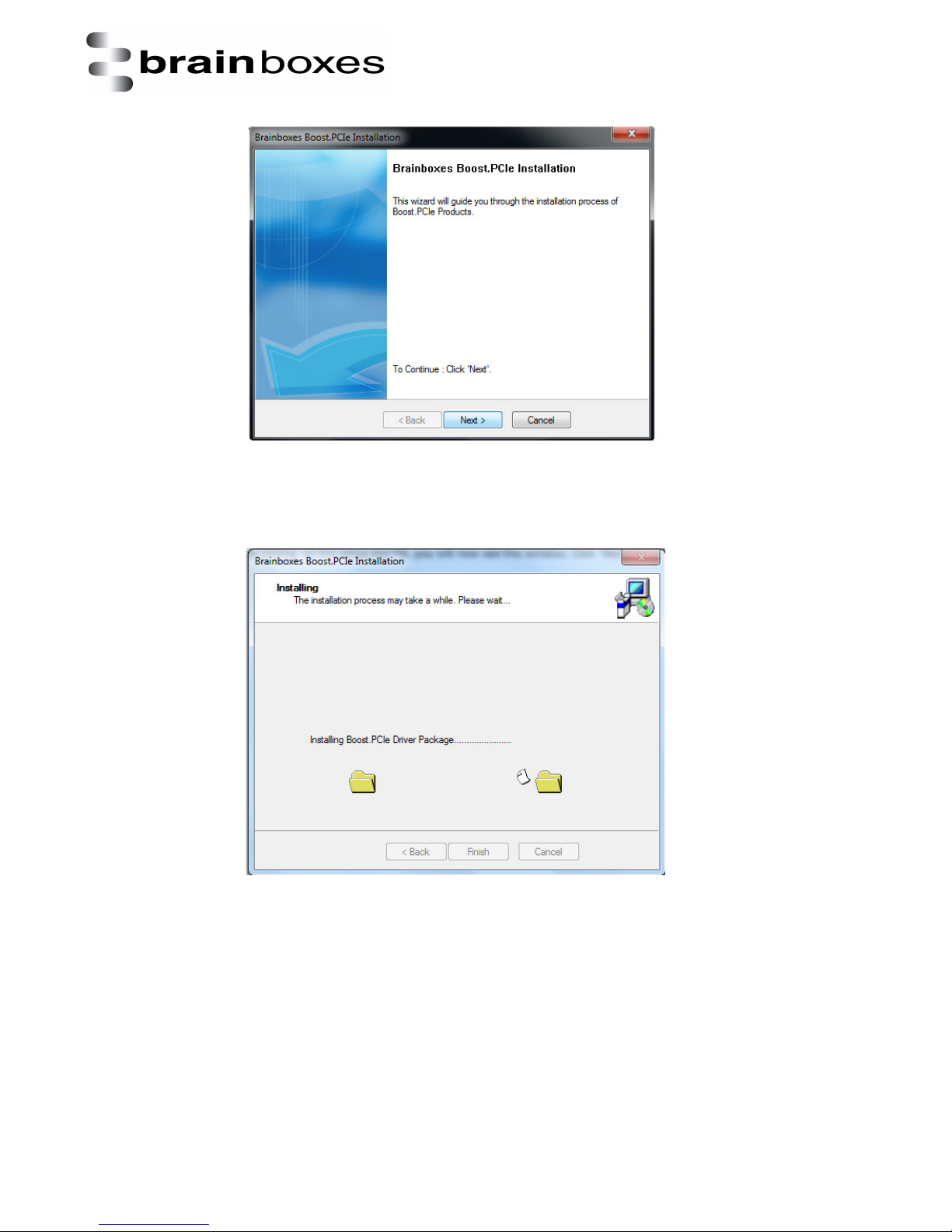
5. After clicking on the setup.exe file, you will now see this window. Click ‘Next >’.
V1.0
© Copyright Brainboxes Ltd Page 13 of
Page 14
Print date: 02/04/2015
XC
Range Product
Manual
38
6. You will know see the drivers begin to install as pictured below.
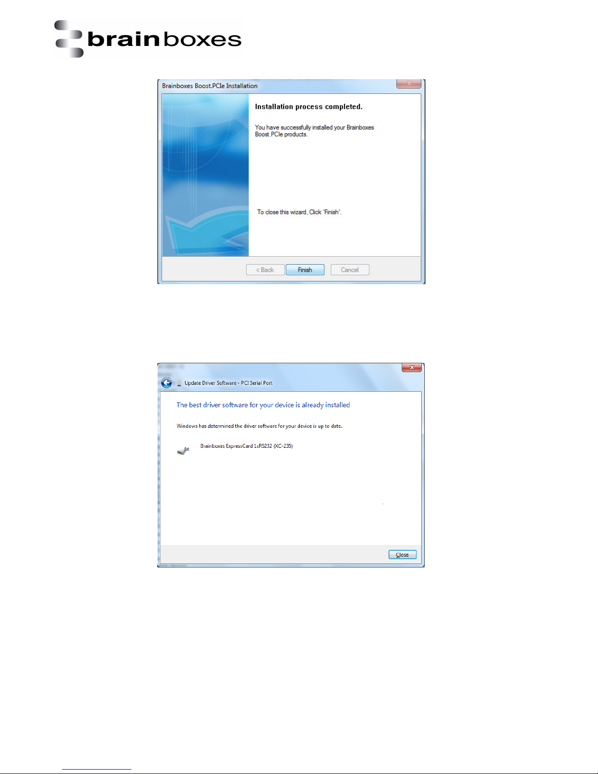
7. After the drivers have installed, you will now be able to see the final installation window.
V1.0
© Copyright Brainboxes Ltd Page 14 of
Page 15
Print date: 02/04/2015
XC
Range Product
Manual
38
8. The following window will now appear showing you that the device has been successfully
installed.
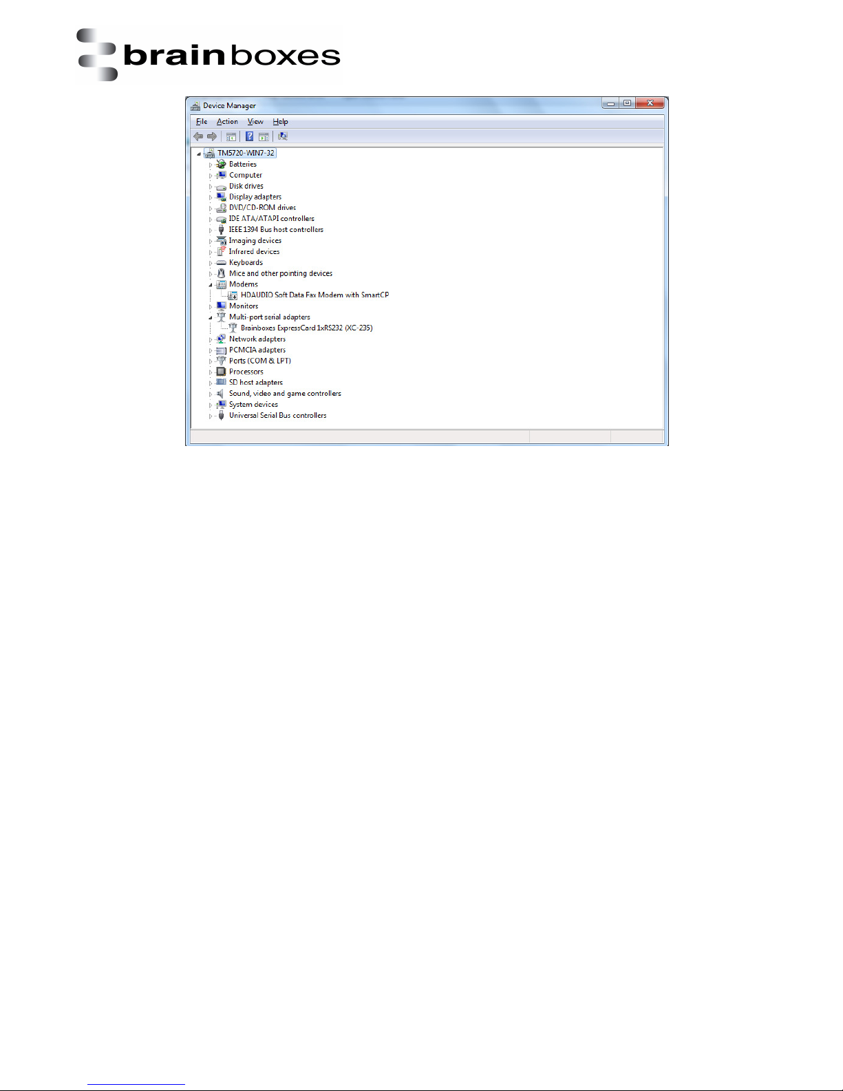
9. Now go to device manager, it will show that the XC-235 has installed. You can now use the
card to transmit and receive data.
V1.0
© Copyright Brainboxes Ltd Page 15 of
Page 16
XC
Range Product
Manual
38
Print date: 02/04/2015
V1.0
© Copyright Brainboxes Ltd Page 16 of
Page 17
Print date: 02/04/2015
XC
Range Product
Manual
38
3.4 Windows 8 installation
The literature below shows an XC-235 device in Windows 8 as an example. The same installation
steps can be applied to all other products in the XC range.
1. Insert the XC CD in to your laptop.
2. Insert the XC-235 in to an available ExpressCard slot on your laptop.
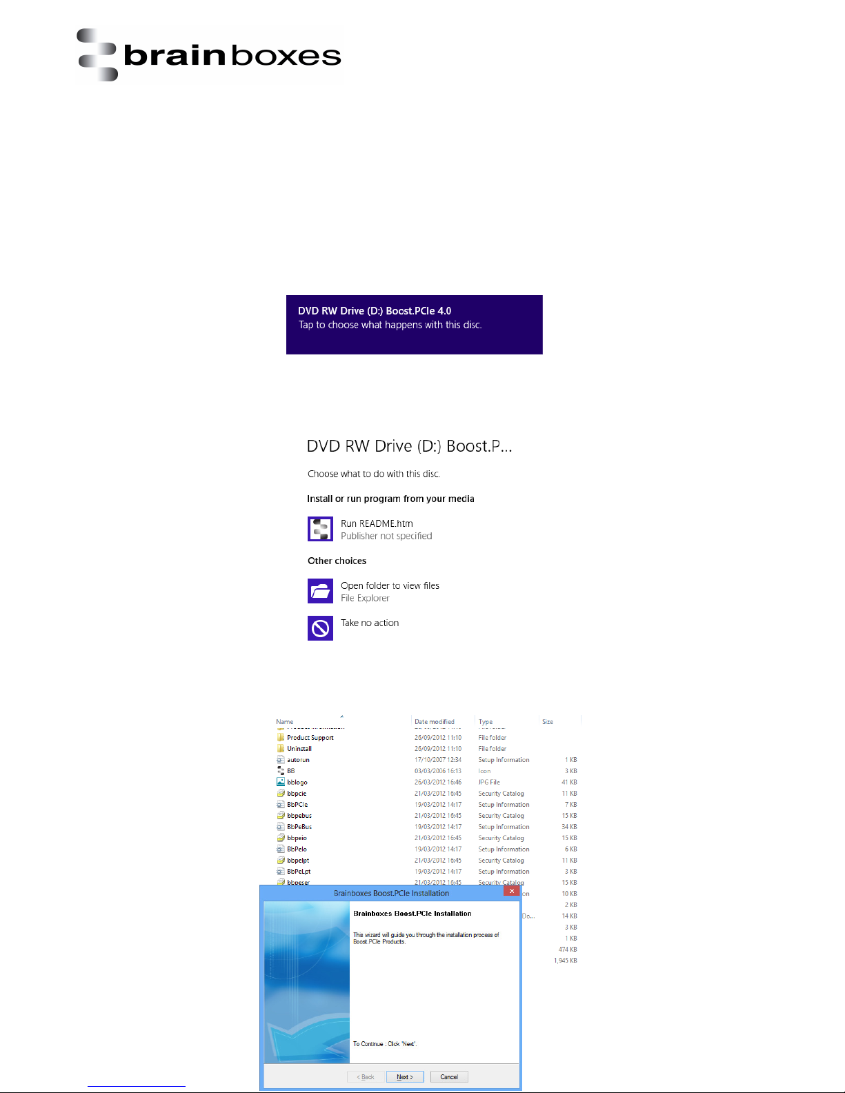
3. You will now see the below window appear. Click on it and a menu will appear.
4. Now select the ‘Open folder to view files’ option from the below window:
5. Go to the bottom of the list of files and select the setup.exe file. This file will install the XC
drivers.
6. Now that you have selected the
V1.0
© Copyright Brainboxes Ltd Page 17 of
Page 18
Print date: 02/04/2015
XC
Range Product
Manual
38
setup.exe file, you will now see a window as shown below, click Next.
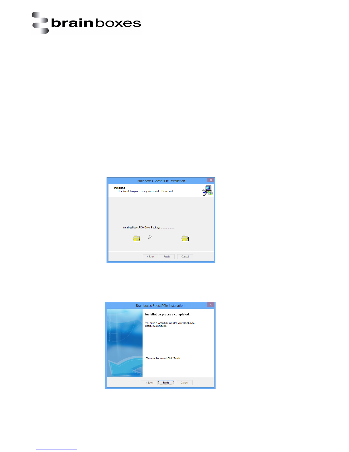
7. When the drivers are installing, the window will look like the one below.
8. When the drivers have been installed, you will then see a similar window as shown.
V1.0
© Copyright Brainboxes Ltd Page 18 of
Page 19
Print date: 02/04/2015
XC
Range Product
Manual
38
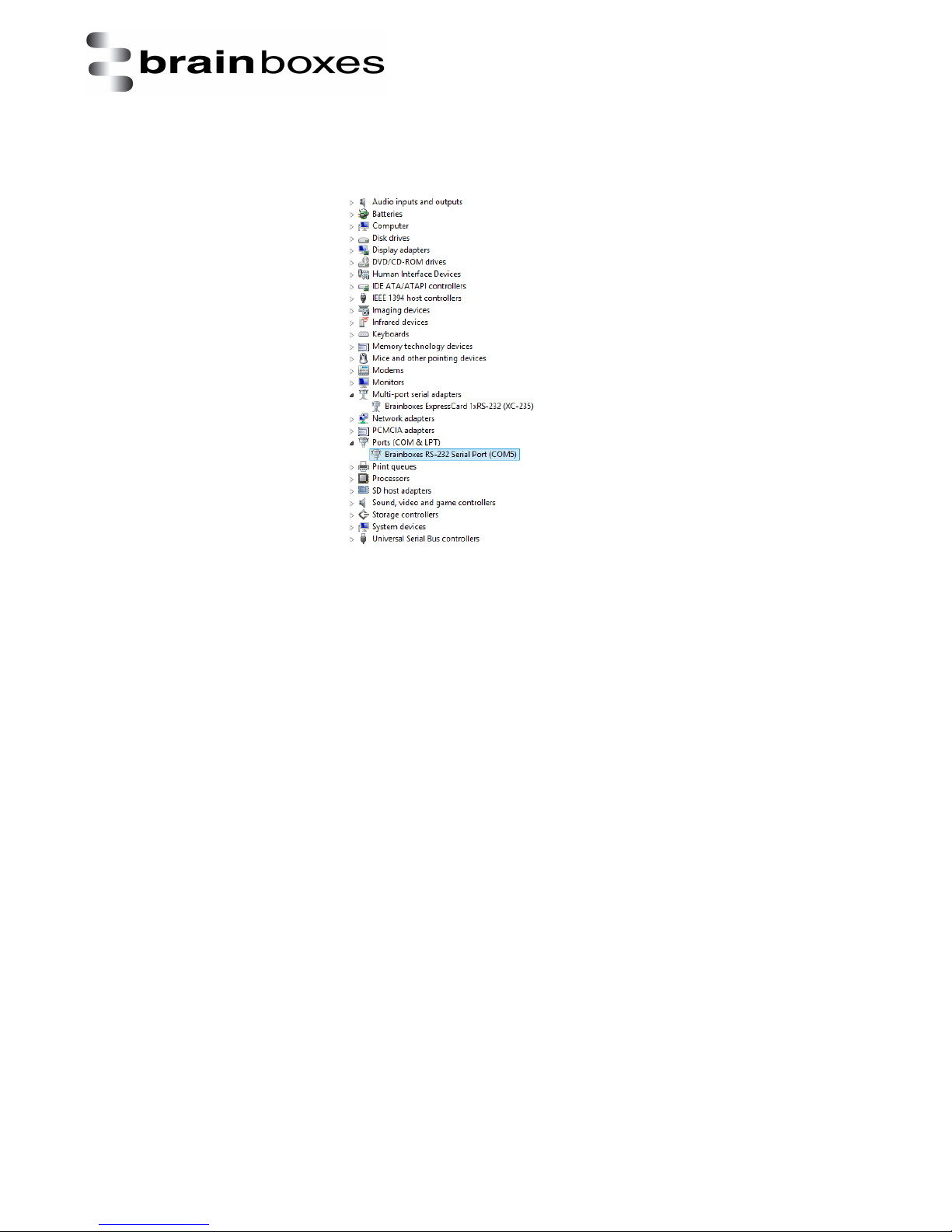
9. When the drivers have installed, Device Manager will now look like the below image. If there
are any yellow exclamation marks over the Brainboxes products, please right click the device and
then update the driver pointing to the files on the CD-ROM.
V1.0
© Copyright Brainboxes Ltd Page 19 of
Page 20
Print date: 02/04/2015
XC
Range Product
Manual
38
4. Product Configuration
4.1 Finding your Brainboxes COM port
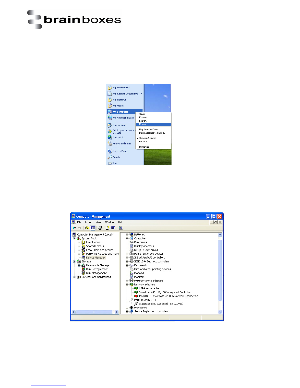
You will need to go to Device Manager (Found by Right Clicking on My Computer and clicking
Manage. Then Select Device Manager from the left hand pane.) For Server 2008 users, Device
Manager is found within Diagnostics in Server Manager.
Find the Brainboxes Serial Port entry in Device manager. (Found under the ‘Ports’ section)
The Brainboxes Serial Port entry displays the current COM number in brackets after the name. (This
is usually COM3 or COM4 following install, but may be different if other serial devices have been
installed in the past)
V1.0
© Copyright Brainboxes Ltd Page 20 of
Page 21
Print date: 02/04/2015
XC
Range Product
Manual
38
4.2 Changing the COM label
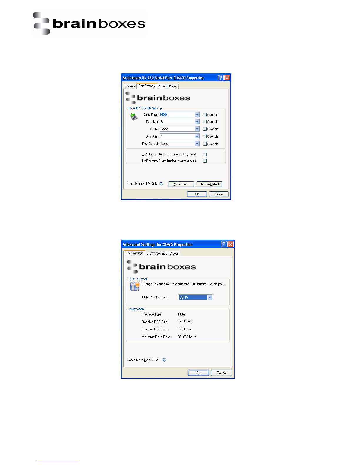
To change the COM label, Double click on the Port entry in Device Manager. You will then need to go
to the Port Settings tab and click on the Advanced button.
You will now see the below window appear. You need to click on the COM port number drop down
list and then select an available COM port.
V1.0
© Copyright Brainboxes Ltd Page 21 of
Page 22
Print date: 02/04/2015
XC
Range Product
Manual
38
4.3 Changing the port settings
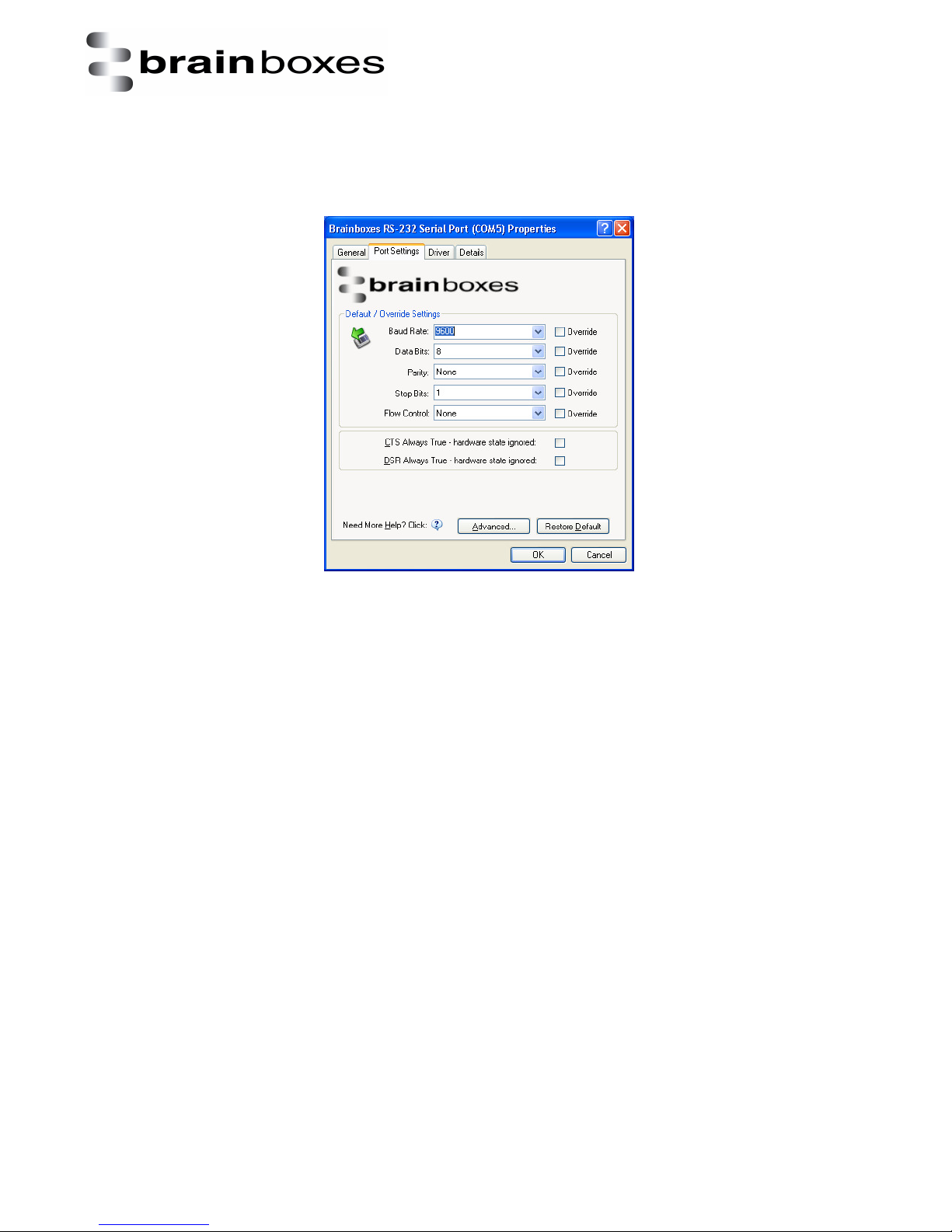
To change the card’s port settings, you will need to open Device Manager and then go to the Port
Settings tab. You can change the baud rate, data bits, parity, stop bits and flow control. You also
have the ability to tick check boxes for CTS Always True and DSR Always True.
All options can be selected from the Dropdown Menus. In addition, you can enter a non-standard
value into the Baud rate
NB – Once the desired settings have been achieved, you must click OK to activate them. At any time
click the ‘Restore Default’ button to return to the original setup.
Default / Override Settings
• The “Default Settings” will be set if an application does not specify the serial settings when it
opens the COM Port.
o This is sometimes the case with old Legacy applications and you will need to choose
these settings to match the communications that you wish to use.
o The majority of Applications will specify what Serial Settings they wish to use. In this
case, it will not matter what the Default settings are, as the Port will be opened with
the Application’s Settings.
• When the ‘Override’ box is checked next to the Default Setting, the Port will communicate at
this setting whether an application has requested it or not.
o For example, this will enable you to force baud rates that your application does not
allow you to select. This can be useful for interfacing to equipment which uses
higher baud rates or unusual baud rates, which your application does not support.
o In a case where you want to use hardware handshaking, but your application is not
capable, you can select RTS / CTS Always True – Hardware state ignored and choose
to Override it.
o NB with the use of Override Settings, you need to ensure that the equipment you
are connecting to be setup to match the communications settings you are forcing.
V1.0
© Copyright Brainboxes Ltd Page 22 of
Page 23

Print date: 02/04/2015
XC
Range Product
Manual
38
CTS / DSR Always True
• CTS and DSR are incoming hardware handshaking lines. This means they receive signals from
the connected device which tell the ExpressCard when it is and isn’t OK to send data.
o Sometimes these signals may want to be ignored. By forcing CTS or DSR True, the
ExpressCard will ignore those signals and always send data.
These settings are especially helpful when CTS and DSR are not physically connected (such as in
a 3 wire setup) and it is not acceptable for the data flow to stop and start due to arbitrary
variances on the unconnected signal lines.
V1.0
© Copyright Brainboxes Ltd Page 23 of
Page 24

Print date: 02/04/2015
XC
Range Product
Manual
38
5. RS-232 Information
5.1 The RS-232 Standard
The RS-232 standard was introduced in 1962, it is now widely established. RS-232 is a slow speed,
short distance, single ended transmission system (i.e. only one wire per signal). Typical RS-232
maximum cable length is 50 feet.
5.2 9 Pin D Serial Port RS-232 Cables
To connect to the RS-232 Serial Port you will need a cable terminating in a 9 way female D
connector. It is sound practice to use cables with screws fitted that will allow you to fasten the cable
securely to the PC card.
In general, you will need to make up a "cross-over" cable to correctly interface the PC to the RS-232
port of another computer or device. Provided you have the pin outs and handshake requirements of
both sides of your RS-232 connection, the cross over cable becomes a matter of common sense. The
cross-over cable is simply to ensure that the right signals going out of one RS-232 port go into the
appropriate lines of the other RS-232 port.
5.3 Pin D serial port connection to another PC
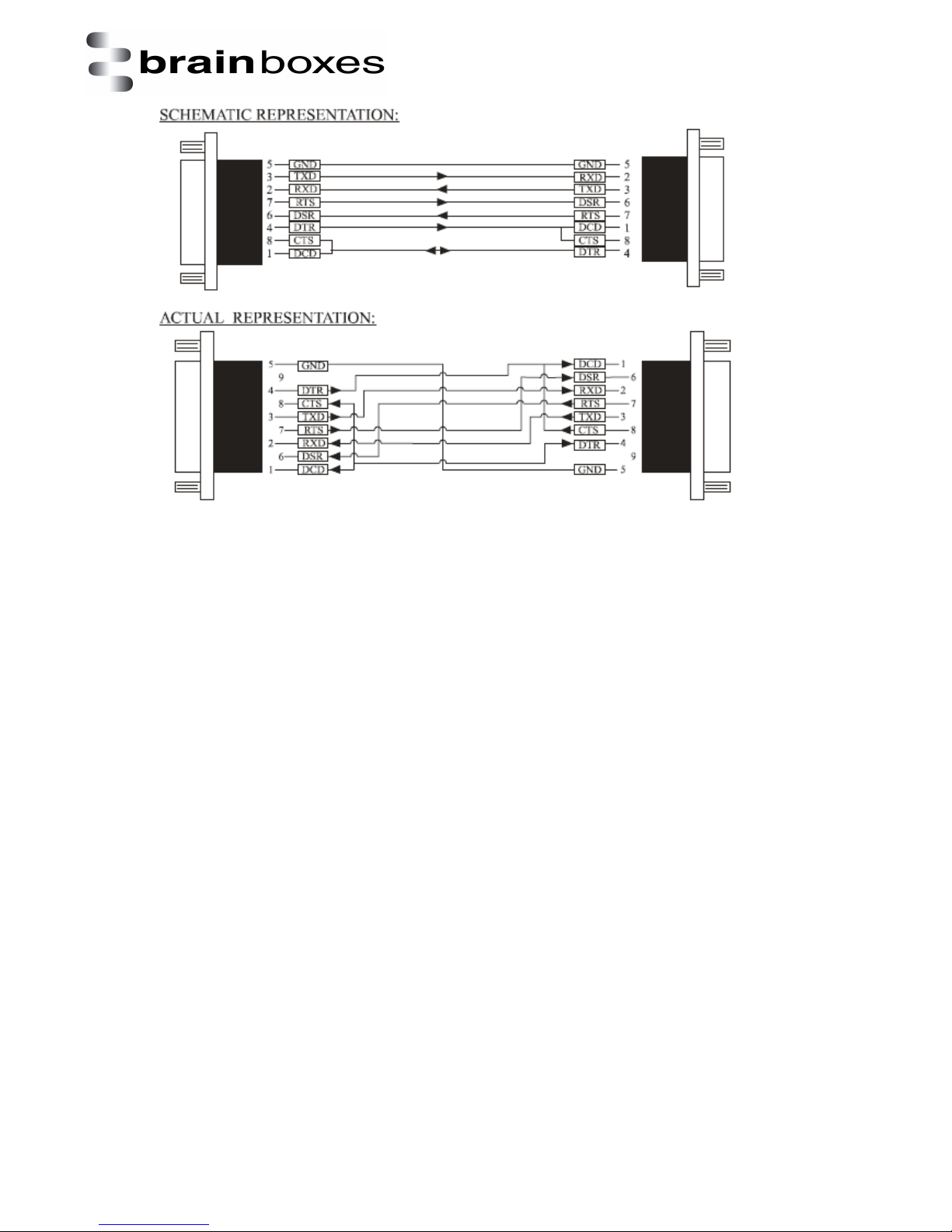
Suppose we want to connect the Brainboxes Serial Port to the serial port of another PC. Connect the
earth lines. Line 5 of Serial Port 2 to lines 1 & 7 of the other PC. This gives the two devices a common
earth level.
Connect the Transmit and Receive lines together. Line 3, TXD, Port 2 goes to line 3, RXD, of the other
PC. Line 2, RXD, Port 2 goes to line 2, TXD, of the other PC. This allows each to receive the data
transmitted by the other.
Connect the Port 2 DTR line, pin 4 to the other PC DCD, pin 8 and CTS, pin 5, lines. Also, connect up
the other PC DTR line, pin 20 to the Port 2 DCD, pin 1 and CTS, pin 8, lines.
This allows the receiving device to signal when it can no longer accept data. The receiving device sets
DTR false when it is unable to receive any more data. The sending device reads DTR on its CTS and
DCD pins. It should stop sending when CTS goes false.
Connect the Port 2 RTS line, pin 7, to the other PC DSR line, pin 6. Also, connect the other PC RTS
line, pin 4, to the Port 2 DSR line, pin 6. This RTS line is used to let the other device know that it is
ready for data exchange.
Schematic and Actual presentations are shown below.
V1.0
© Copyright Brainboxes Ltd Page 24 of
Page 25
Print date: 02/04/2015
XC
Range Product
Manual
38
V1.0
© Copyright Brainboxes Ltd Page 25 of
Page 26
Print date: 02/04/2015
XC
Range Product
Manual
38
6. LPT printer port information
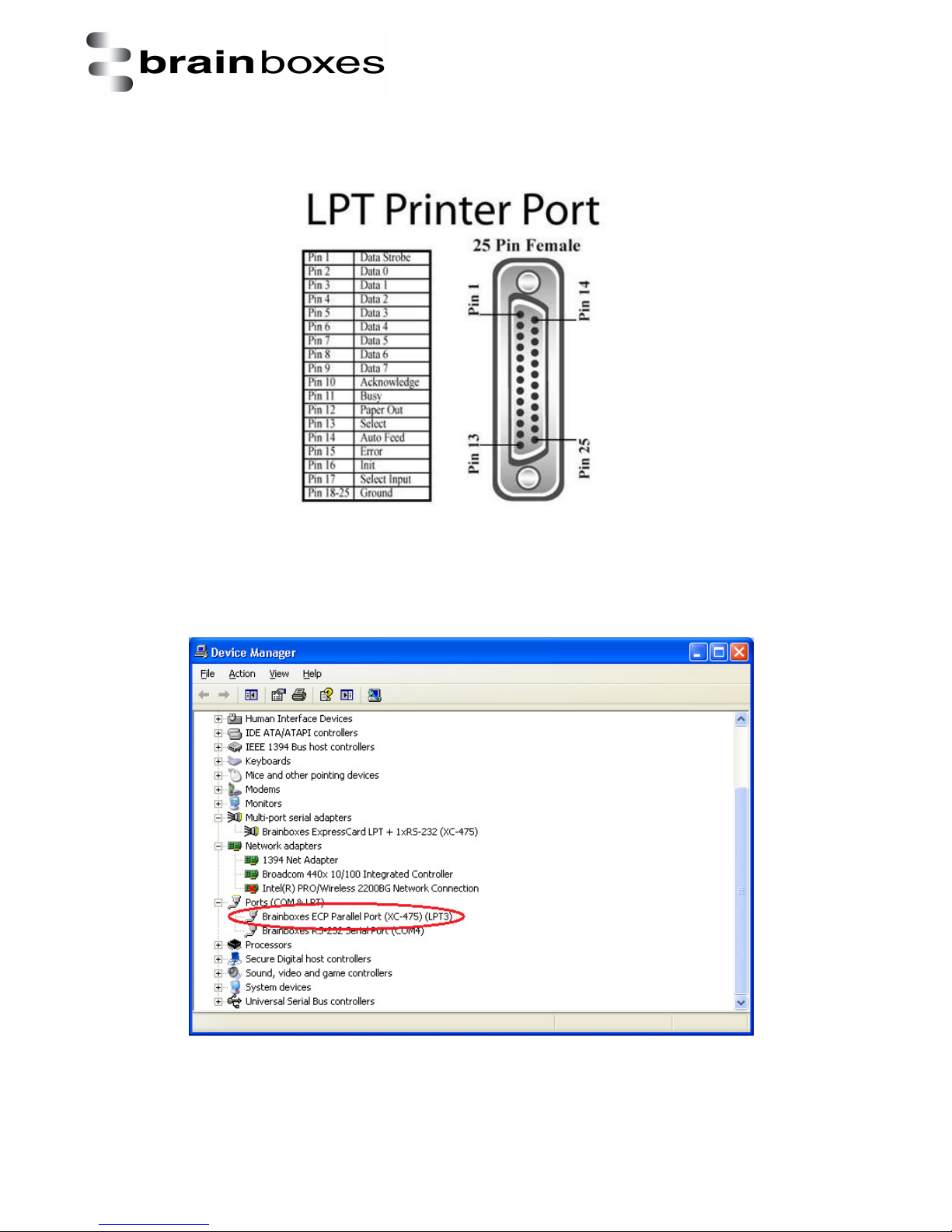
Below is the pinout for the LPT printer port which is used on the XC-157 and XC-475 ExpressCard’s.
When selecting the appropriate LPT port in your application, you will need to check device manager
to see which LPT port you need to use. Please see below the LPT port in the red circle and then
choose the correct port in your application for it to be used.
V1.0
© Copyright Brainboxes Ltd Page 26 of
Page 27
Print date: 02/04/2015
XC
Range Product
Manual
38
7. UART Settings
The UART settings for the Brainboxes COM Port allow you to get the best performance from your
device and system. There are two choices, dependant on whether minimal CPU usage or Data
Latency (delay) is the main concern.
The default settings have been carefully selected and should provide great performance for the
majority of users. The UART Settings will help if you need to lower the CPU usage, or your
application is timing critical and requires a lower Data Latency
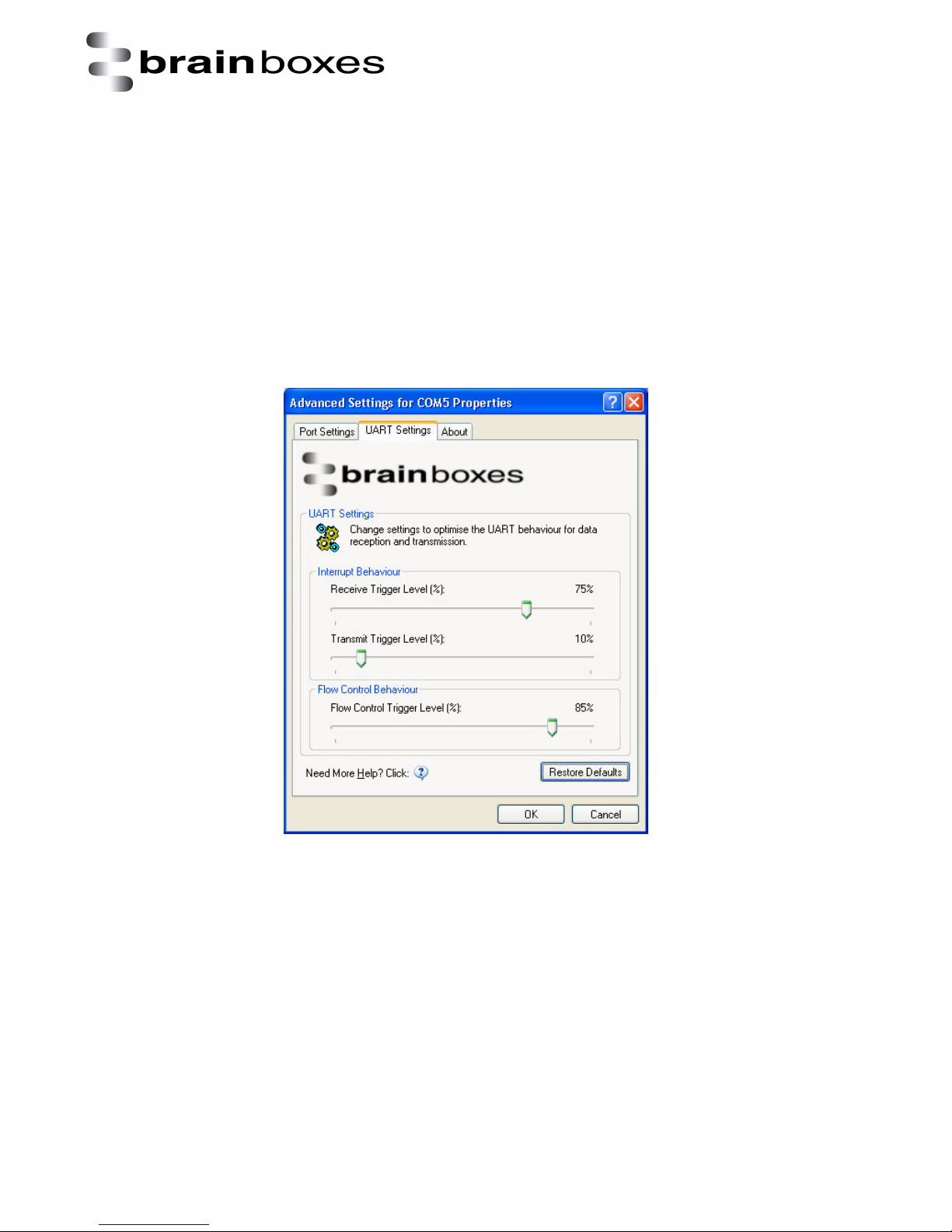
• To open Advanced Settings, open the Port Settings and click the Advanced button
• Select the ‘UART Settings’ tab.
V1.0
© Copyright Brainboxes Ltd Page 27 of
Page 28

Print date: 02/04/2015
XC
Range Product
Manual
38
7.1 Receive Trigger Level
This slider allows you to choose how much incoming data is stored in the Receive FIFO before it gets
processed by the driver.
Processing the data takes a small amount of CPU time, so doing this frequently will increase CPU
Usage, but it will also decrease the latency at which data is delivered to the application. Choosing
the right value is a trade-off between CPU Usage and Latency.
Setting this value very low will result in a high number of interrupts, and therefore increased CPU
Usage, as well as short latency times between the reception of the data by the UART chip and the
delivery to the application. Choosing a high value has the opposite effect.
If the Receive Trigger Level is chosen very high, and data is continuously streaming into the UART's
FIFO, then this might result in data getting lost due to a FIFO Overrun. This is caused by the reaction
time of the Operating System and driver to the interrupt. If this reaction time is longer than it takes
to fill up the remaining space in the FIFO, then overrun can occur. To prevent this, choose a slightly
lower Receive Trigger Level, and use Flow Control.
7.2 Transmit Trigger Level
This slider allows you to choose when the Transmit FIFO is re-filled with data. If a low value is
chosen, little or no data is left in the Transmit FIFO at the time of the re-fill. The higher the value, the
more data will be in the FIFO.
Re-filling the Transmit FIFO before it runs empty has the advantage that the small processing time
required to generate the interrupt notification to the driver and putting data into the FIFO will not
have the effect of a gap appearing in the data stream on the transmission line.
It is not common to choose high values for this slider, as the potential transmission gap is easily
bridged, even if values are chosen in the lower part of the slider. Higher levels increase the amounts
of hardware interrupts generated, and hence increase CPU usage.
The slider allows choosing values from 0% to 100% of the Transmit FIFO size.
7.3 Flow Control Trigger Level
The slider only takes affect if any type of flow control was selected by the application that opened
the COM port.
This slider allows you to choose when the flow control state changes (RTS, DTR, in-band flow
control). If the amount of received data reaches the Flow Control Trigger Level, any active flow
control mechanism is set to the 'do not send' state. Once the amount of received data falls again
below this level, all active flow control mechanisms are returned to the 'send data' state.
Depending how handshaking is implemented on the device at the other side of the cable, it is
possible that some data is still transmitted to our UART even after handshaking has been turned off.
Setting very high Flow Control Trigger Levels might in this case result in a FIFO overrun, and hence
the loss of data.
It is not common to choose low values for this slider, as this increases the amount of handshaking
changes on the line. That might increase the processing overhead on the remote device, and result
in gaps in the data stream, thus reducing data throughput. Usually values are chosen in the higher
part of the slider.
V1.0
© Copyright Brainboxes Ltd Page 28 of
Page 29

Print date: 02/04/2015
XC
Range Product
Manual
38
The slider allows choosing values from 1% to 100% of the Receive FIFO size.
Pressing the “Restore Defaults” button will reset all settings on this Property Page to the factory
defaults of this device.
The factory defaults are:
• Receive Trigger Level (%) = 75%
• Transmit Trigger Level (%) = 10%
• Flow Control Trigger Level (%) = 85%
V1.0
© Copyright Brainboxes Ltd Page 29 of
Page 30
Print date: 02/04/2015
XC
Range Product
Manual
38
8. Uninstallation instructions
8.1 Windows Server 2008/Vista/Server 2003/XP
To uninstall the device, please ensure the PCI Express Card is present on the PC.
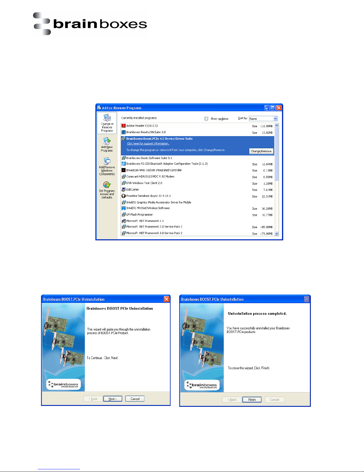
Open Control Panel, and then open “Add or Remove Programs”. In Vista, this will be called
“Programs & Features”.
The Brainboxes Uninstallation wizard will launch which will remove all driver files and associated
registry entries. Just click Next on each page of the Wizard. When the drivers have been uninstalled,
click Finish.
Once finished, check Device Manager to ensure all Ports have been removed from the system.
V1.0
© Copyright Brainboxes Ltd Page 30 of
Page 31

Print date: 02/04/2015
XC
Range Product
Manual
38
You may now power down the PC and unplug your XC card.
To reinstall the software, simply Right Click the “Ports” entry in Device Manager and select “Scan for
Hardware Changes”. Windows should find the ports and launch the Found New Hardware wizard.
Follow the installation instructions as in Section 3 to reinstall.
Alternatively, restart the PC to launch the Found New Hardware Wizard.
V1.0
© Copyright Brainboxes Ltd Page 31 of
Page 32
Print date: 02/04/2015
XC
Range Product
Manual
38
9. Boost.PCIe Driver Upgrade / Rollback
There are several parts to the Boost.PCIe, driver:
For RS-232:
Example
• Card driver: “Brainboxes ExpressCard 1xRS-232 (XC-235)”
• Port driver: “Brainboxes RS-232 Serial Port (COM4)”
For LPT :
• Card driver: “Brainboxes ECP Parallel Port (XC-475) (LPT3)”
• Port driver : “Brainboxes RS-232 Serial Port (COM4)”
NB - If you need to upgrade or roll back the Boost.PCIe driver, we recommend to completely
uninstall the existing drivers first, and then to install the new drivers from fresh. This will restore all
settings to factory default. However, if you instead wish to retain your settings, you can use the
‘Update Driver’ or “RollBack” in Device Manager for upgrading/rolling back the Boost.PCIe driver.
9.1 Upgrading the Boost.PCIe Driver
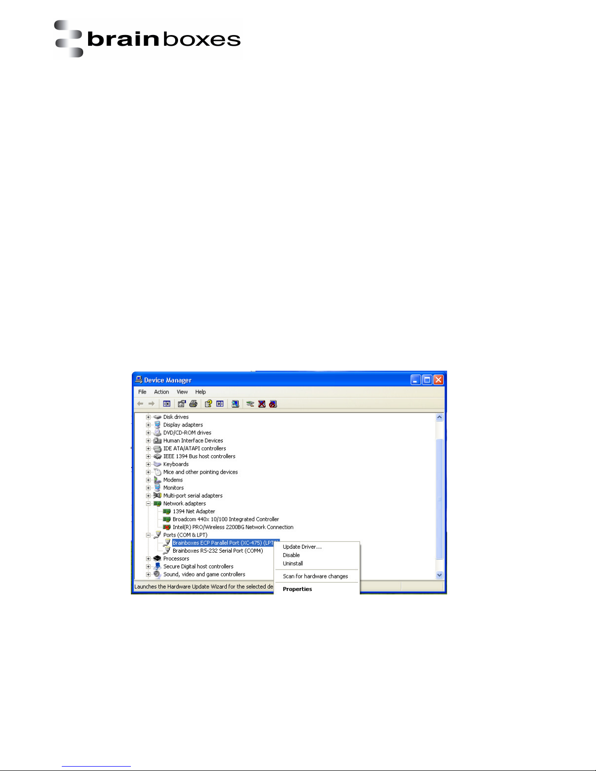
i. Go to Device Manager and Right Click on the Serial Card entry (Found under Multiport Serial
Adapters – see image below)
ii. Select Upgrade Driver. This will launch the Found New Hardware Wizard. Follow the on
screen instructions and point to the location of the new driver package.
NB: It is only possible to upgrade the Boost.PCIe driver via the ExpressCard entry in Device Manager
and not the Serial Port entry. The upgrade process will automatically upgrade the Port driver.
V1.0
© Copyright Brainboxes Ltd Page 32 of
Page 33

Print date: 02/04/2015
XC
Range Product
Manual
38
10. Troubleshooting and Testing
10.1 Installation problems
Check the XC is correctly installed, and the Ports appear in Device Manager without any errors
(Errors are indicted by a yellow exclamation mark)
If the installation did not complete or shows any error messages then restart the computer.
If Device Manager is still showing error messages, it is wise to uninstall and re-install. This should
cure issues such as Resource Conflicts or failed installations. See Section 8: Uninstallation and
Section 3: Installation Instructions.
If the problem is still present after trying the above, try the following to help narrow down the
problem.
1. A different ExpressCard Slot
2. A different PC
Should the problem still persist, please contact Brainboxes Technical Support
10.2 Communication Problems
If you are experiencing communication problems:
Check the XC is correctly installed, and the Ports appear in Device Manager without any errors
(Errors are indicted by a yellow exclamation mark).
Perform a loopback: A loopback test will verify that your card is able to Transmit and Receive Data.
The Transmit and Receive lines will need to be connected so that any data sent out of the card is
then received back on the same Port.
Here are two links to our website to help perform a loopback test:
http://www.brainboxes.com/faq/items/how-do-i-create-a-loop-back-connector
http://www.brainboxes.com/faq/items/how-to-user-hyperterminal-to-test-serial-cards
Should the problem still persist, please contact Brainboxes Technical Support
10.3 Testing your serial COM port
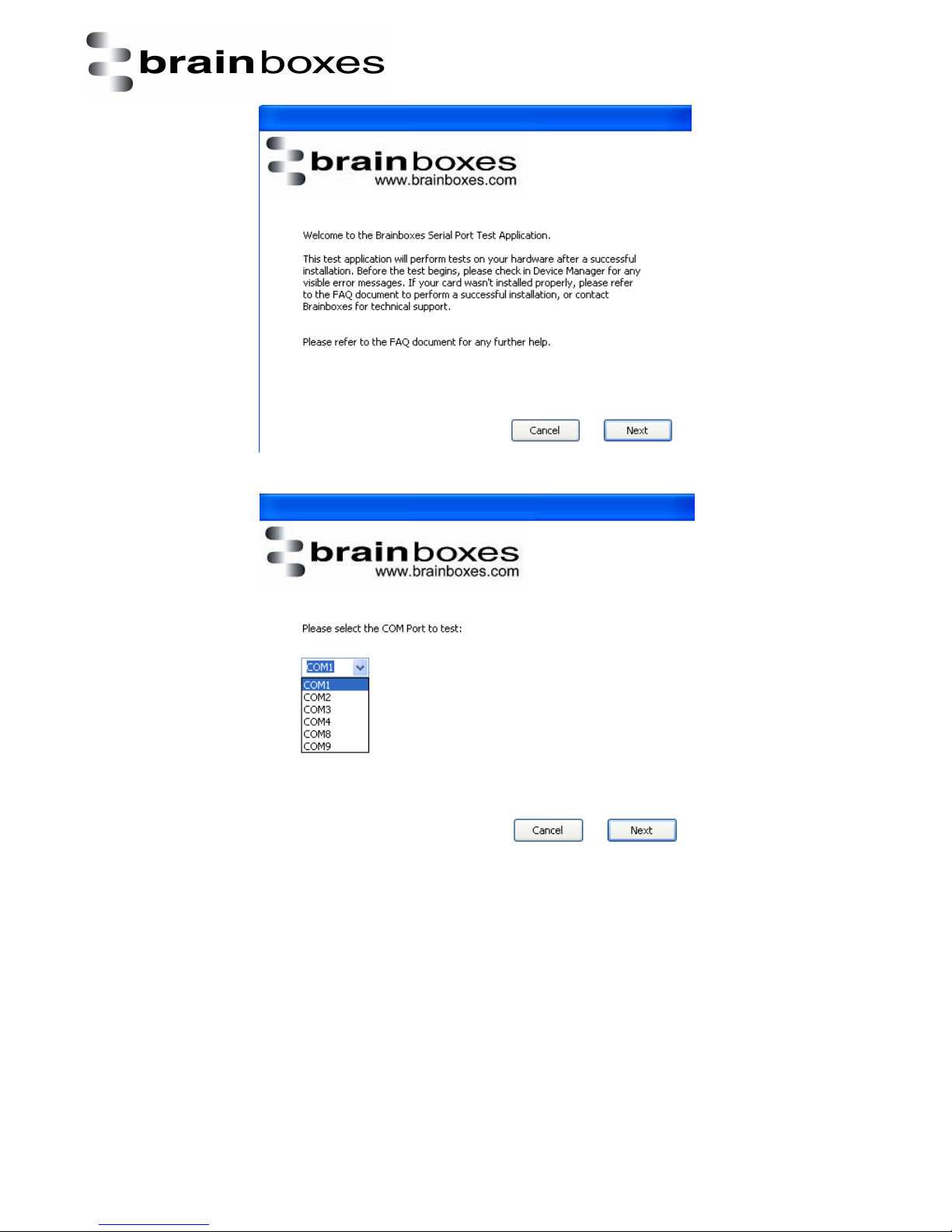
To test your Brainboxes COM port works correctly you can use the Serial Test application. It is a
simple application which will guide you through the steps to check that your Brainboxes COM port is
working correctly.
You will need to select the COM port you want to test, and connect a loopback connector to
transmit and receive pins of the respected COM port. You will then be given a result as to whether
the test has passed or failed.
V1.0
© Copyright Brainboxes Ltd Page 33 of
Page 34
XC
Range Product
Manual
38
Print date: 02/04/2015
V1.0
© Copyright Brainboxes Ltd Page 34 of
Page 35

Print date: 02/04/2015
XC
Range Product
Manual
38
11. Lifetime warranty and support
To receive the lifetime Warranty, you need to register your product with us using our online form.
NB: this must be done within 28 days of Purchase.
Lifetime Warranty Sign up
* Terms and Conditions are available online. Standard warranty period is 3 years if a product is not registered.
Since 1983, Brainboxes have designed, tested and manufactured our
products all under one Roof. One of our greatest strengths is in after sales
service. Technical Support is provided by members of our Test Team, who
know our products inside out and have direct access to the chip and board
designers as well as the technicians who built and tested your product.
If you have any issues, questions or suggestions about our Products and
Services, then please contact us.
Technical Support is free*. As long as you have a Brainboxes Product we will be happy to help, even
if it’s discontinued or out of warranty. Excellent Customer Service, just as it should be.
For the quickest solution to your issue, if you email us, please include as much detail of your setup
and the fault you are experiencing.
* Standard rate call charges for phone support apply.
Email
Technical Support: [email protected]
Sales Enquiries: [email protected]
Telephone
You can speak to Brainboxes Support or Sales teams direct,
Monday – Friday, 9am to 5pm (UK time)
Tel: +44 (0)151 220 2500
V1.0
© Copyright Brainboxes Ltd Page 35 of
Page 36
XC
Range Product
Manual
38
12. Technical specification
Baud Rate
Up to 921,600
Data Bits
5,6,7 or 8
Parity
None,
Odd, Even, Mark & Space
Stop Bits
1 or 2
Handshaking
RTS/CTS DTR/DSR Xon/Xoff
12.1 Support serial settings
Print date: 02/04/2015
Serial Setting
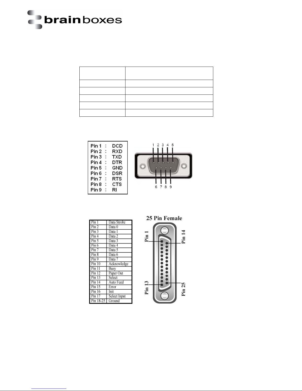
12.2 RS-232 Pinout
12.3 LPT pinout
V1.0
© Copyright Brainboxes Ltd Page 36 of
Page 37

Print date: 02/04/2015
XC
Range Product
Manual
38
13. Regulatory Approvals / Compliance
For up to date details of global certifications, please check the product datasheet on the Brainboxes
website: www.brainboxes.com
13.1 Company Accreditation
Brainboxes is accredited to internationally recognised standards for our Quality and Environmental
Management Systems. Our ISO9001 Quality System was first accredited in 1994, followed by our
ISO14001 Environmental System in 2008. These standards help ensure we can demonstrate effective
management of all our quality systems and our environmental impacts, together with a process of
continuous improvement.
All our Quality systems are subject to internal and external assessment on a regular basis. Copies of
Certificates are available for download from our website: www.brainboxes.com
Linked with our Lean and Six Sigma techniques, we believe we have the most reliable products on
the market, and to back this up we are offering a Lifetime Warranty* on all our Serial Products.
13.2 Europe – EU Declaration of Conformity
Brainboxes products are designed to conform to the protection requirements of European Council
Directive 2004/108/EC and its subsequent revisions.
A Declaration of Conformity and supporting Technical Construction File is available by request from
Brainboxes, and will identify any updated legislation that may have been introduced since the
publication of this Manual.
Warning: This is a Class A Product. In a domestic environment this product may cause interference in
which case the user may be required to take adequate measures to address this.
13.3 WEEE Directive (Waste Electrical and Electronic Equipment)
The Waste Electric and Electronic Equipment (WEEE) Regulations 2013 became law in the UK on the
1st of January 2014 and replaced the 2006 Regulations. Brainboxes is fully compliant with this
legislation.
Customer Responsibilities
You are encouraged to dispose of WEEE in an environment friendly way.
This can be done through your local civic amenities site, an approved treatment facility or
alternatively through a relevant compliance scheme.
Brainboxes’ Responsibilities
Brainboxes has a legal responsibility, as producer, to provide a free of charge collection service to
our customers for our obligated WEEE.
Brainboxes is defined as a producer under the WEEE regulations because we sell own brand
Electrical & Electronic Equipment (EEE) in the UK. Our WEEE Producer Registration Number is
WEE/AH0004XR. For details of our WEEE recovery service options, please see our Website, or email
us at: [email protected]
V1.0
© Copyright Brainboxes Ltd Page 37 of
Page 38

Print date: 02/04/2015
XC
Range Product
Manual
38
13.4 RoHS Compliance
All Brainboxes Serial and Bluetooth products are fully RoHS compliant.
Brainboxes identified at an early stage the importance of rapid compliance to RoHS
guidelines and established a project team to actively manage the transition. The initial step
in the process was to use our close relationships with suppliers to ensure early access to
RoHS compliant components for all of our Bluetooth and Serial Products. In addition, the
project team worked to ensure that our manufacturing processes meet all RoHS
requirements well in advance of the deadline.
To verify supplier declarations on RoHS compliancy, we have also sent fully built products to
an external test house for X-Ray system XDAL. This technique is capable of determining
percentages of different elements and is accurate to 0.1% Wt.
RoHS Compliant Brainboxes products have been available since January 2005.
What is the RoHS Directive?
The Restriction of the Use of Certain Hazardous Substances (RoHS) in Electrical and
Electronic Equipment (EEE) Directive (2011/65/EU) was transposed into UK law on 2
January 2013.
This legislation bans the placing on the EU market of new EEE containing more than the
agreed levels of:
•
lead (Pb)
•
cadmium (Cd)
•
mercury (Hg)
•
hexavalent chromium (Cr6+)
•
polybrominated biphenyls (PBB)
•
polybrominated diphenyl ethers (PBDE)
Any future revisions to this legislation will be complied with, and identified in a Declaration of
Conformity, available on request.
14. Copyright
Copyright © Brainboxes Ltd
All rights reserved. No part of this hardware, software, circuitry or manual may be duplicated,
copied, transmitted or reproduced in any way without the prior consent of the Manufacturer.
V1.0
© Copyright Brainboxes Ltd Page 38 of
 Loading...