

Page 1

Hardwar e Manual
2
3
2
232
232
QUAD RS232
2.0 EDITION JUNE 1999
Page 2

Guarantee.
FULL 36 MONTHS GUARANTEE.
We guarantee your Serial Port Card for a full 36 months from
purchase, parts and labour, provided it has been used in the
specified manner. In the unlikely event of failure return your
interface to your Dealer, with proof of purchase, who will
determine whether to repair or replace this product with an
equivalent unit.
COPYRIGHT.
COPYRIGHT © 1985-1999.
All rights reserved. No part of this hardware, circuitry or manual
may be duplicated, copied, transmitted or reproduced in any way
without the prior written consent of the Manufacturer.
Due to the Manufacturers commitment to quality, software is
subject to continuous improvements: information regarding
upgrades can be obtained from your supplier.
Serial Solutions is supplied to you by
ACKNOWLEDGEMENTS.
IBM, COMPAQ, Hewlett Packard, H.P. and EPSON are
trademarks of the relevant companies. Windows is a trademark of
Microsoft.
Page 3

PCI Quad RS232 Layout
THE LAYOUT OF THIS MANUAL
Chapter 1 - PCI Quad RS232 Hard ware
Configuration, after a brief discussion on the RS232
standard shows how to configure the settings of the
cards. Details of COM, IRQ and Shared Interrupt
mechanisms are given.
Chapter 2 – Installing the card into the PC, shows you
how to install the card into a IBM PC or c ompa tible.
Chapter 3 – PCI Quad RS232 Software Installation
Chapter 4 – PCI Quad RS232 DOS Installati on
Chapter 5 –RS232 Port Cabling
INTRO 5
Page 4

PCI Quad RS232 INDEX
Index
THE LAYOUT OF THIS MANUAL..................................... 5
CHAPTER 1 PCI QUAD RS232 HARDWARE
CONFIGURATION. ....................................................8
Introduction...........................................................................8
PCI QUAD RS232 Card Features..........................................8
CHAPTER 2 INSTALLING THE PC CARD IN
THE COMPUTER.....................................................11
Serial Carrd Inst a l l a t i o n . ....................................................... 11
Proble m s! ............................................................................ 13
CHAPTER 3 PCI QUAD SOFTWARE
INSTALLATION .......................................................14
Introduction......................................................................... 14
Configuring Ports In Windows 3.x....................................... 14
Determining PCI Quad RS232 Resources............................14
Windows 3.x Software Installation.......................................15
Serial Port Installation.......................................................... 17
Configuring The COM Ports................................................ 20
Deleting Ports in Windows. ................................................. 21
Restarting Windows............................................................. 21
Warning............................................................................... 21
Installing Ports In Microsoft Windows 95 & 98................... 22
Quad RS232 Card Settings................................................... 26
Quad RS232 Port Settings.................................................... 28
Configuring Ports In Microsoft Windows NT 4.0.................31
Software Installation............................................................ 31
Examining Card Configuration............................................ 33
Configuring Ports. ............................................................... 34
Uninstalling Serial Solutions PCI......................................... 35
CHAPTER 4 PCI QUAD DOS INSTALLATION
PROCEDURE.............................................................36
Determining PCI Quad Resources........................................ 36
Informing The PC Of The Port Address...............................37
INTRO 6
Page 5

PCI Quad RS232 INDEX
Settings for DOS Software................................................... 39
I/O Address. ........................................................................ 41
Number Buffers...................................................................42
Hardware Handshake........................................................... 42
Hardware Interrupt............................................................... 43
4 Port RS232 cards.............................................................. 44
Buffer Size. ......................................................................... 45
Software Handshaking......................................................... 46
Driver Defaults....................................................................46
CHAPTER 5 RS232 PINOUTS AND PORT
CABLING...................................................................48
Introduction......................................................................... 48
The RS232 Standard............................................................48
Serial Port Pin Outs. ............................................................49
9 Pin D Serial Port RS232 Cables........................................ 49
9 Pin D Serial Port Connection To Another PC.................... 50
9 Pin D Serial Port To A Modem......................................... 52
9 Pin D Serial Port Loop Back Connector............................ 52
INTRO 7
Page 6

PCI Quad RS232 Hardware Configuration
CHAPTER 1
PCI QUAD RS232 HARDWARE
CONFIGURATION.
Introduction.
This chapter explains how to configure the PCI QUAD RS232 in a
PC compatible.
This three quarter size RS232 card will work happily in any PC
compatible up to and exceeding Pentium III 550 MHz class
machines.
PCI QUAD RS232 Card Features.
• Four independent modified RS232 Serial ports.
• Reliable communications up to 50 feet, 15m, and beyond!
• 100% PC Compatible serial port TI 16C554, up to 115,200
baud.
• Fully Plug and Play
• Operationally PCI 2.1 compliant
• Modem control TXD, RXD, DSR, DTR, RTS, and CTS
signals.
• Fully double buffered for reliable asynchronous operation.
• High-speed integrated circuitry ensures operation with fast
PC’s e.g. 550 MHz Pentium III WITHOUT extra wait states.
• 16554 FIFO provides 16-byte input and 16-byte output buffer
on each port.
Chapter 1 Page 8
Page 7

PCI Quad RS232 Hardware Configuration
The PCI QUAD RS232 has the following features:
Baud Rate: 50 Baud to 115200 Baud.
Word Length: 5, 6, 7 or 8 bits.
Parity: Even, Odd, None, Mark or Space.
Start Bit: 1 start bit always sent.
Stop Bits: 1, (1.5 for 5 bit data word length) or 2.
Clock Input: 1.8432 MHz.
Chapter 1 Page 9
Page 8
PCI Quad RS232 Hardware Configuration
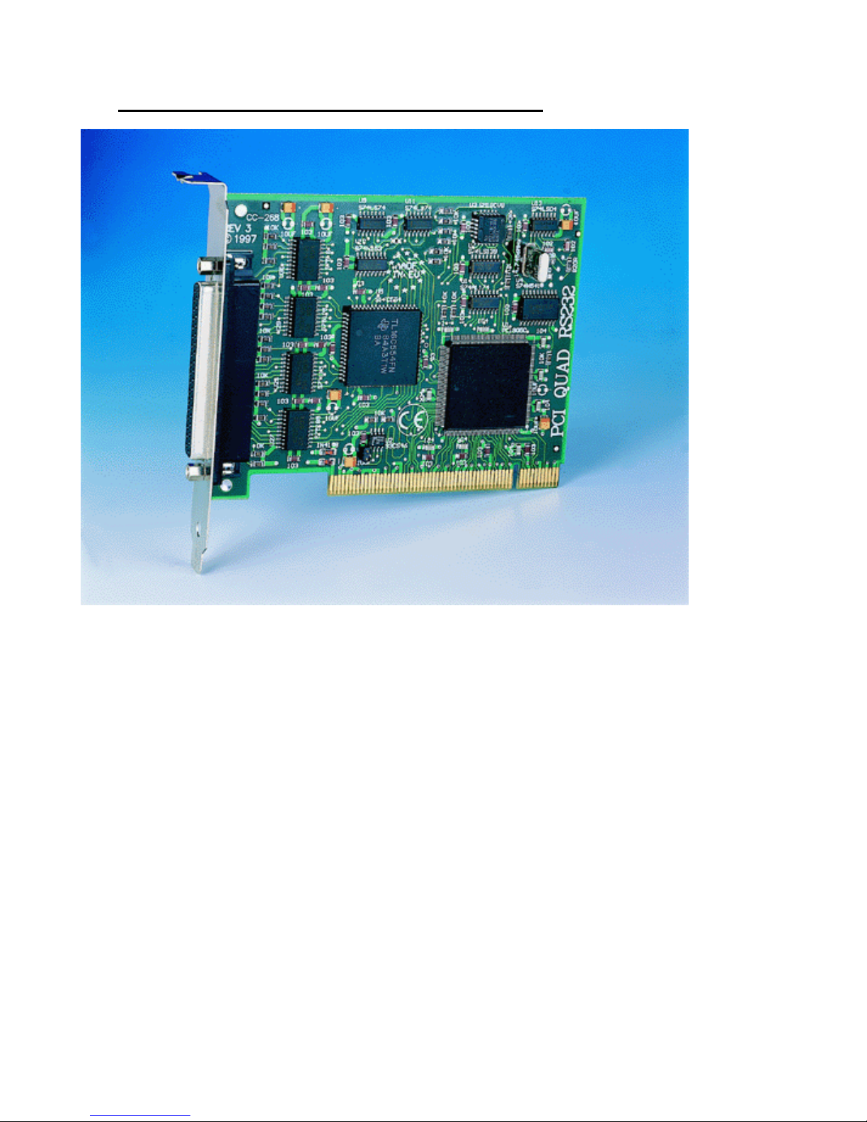
Figure 1-1. PCI QUAD RS232 Layout
PCI QUAD RS232 Specifications:
Dimensions: 105 x 170 mm, 4.13 x 6.8 in
I/O Connection: 4 nine pin serial ports
Serial Port 1: 9 pin Male D type.
Serial Port 2: 9 pin Male D type.
Serial Port 3: 9 pin Male D type.
Serial Port 4: 9 pin Male D type.
The PCI Quad is fully Plug and Play, it’s address and interrupt
settings will be fully configured by YOUR system.
Chapter 1 Page 10
Page 9

PCI Quad RS232 Installing the Card
CHAPTER 2
INSTALLING THE PC CARD
IN THE COMPUTER.
Serial Carrd Installation.
Once the card has been correct ly configur ed it can then be
installed in the PC. For the PCI card it is best to make a note of the
serial port I/O address selection and if appropriate IRQ jumper
settings for later use.
Finally cables should be attached and communication with
the serial peripheral devices should be established.
Provided that the RS232 installation is attacked in this
orderly manner, everything should work first time. If it does not
then check the software sel ectabl e comm unicat ions par am eter s,
Baud rate, Parity, stop bits first, and that the communications
program is attem pt i ng to access the serial por t i nst al led. I f this fails
to solve the problem check the cable connecti ons. Final ly check
that the card is indeed configured as you believed.!
NOTE: Always turn the computer OFF before installing or
removing any interface board..!!!
After having made sure that the I/O address and if appropriate
jumpers are correctly set, now is the time to insert the PC Serial
card into the I/O connector slots in the computer.
STEP 1: Before the PC card can be installed the power to the PC
MUST be switched OFF!
STEP 2: Remove t he case.
Chapter 2 Page 11
Page 10
PCI Quad RS232 Installing the Card
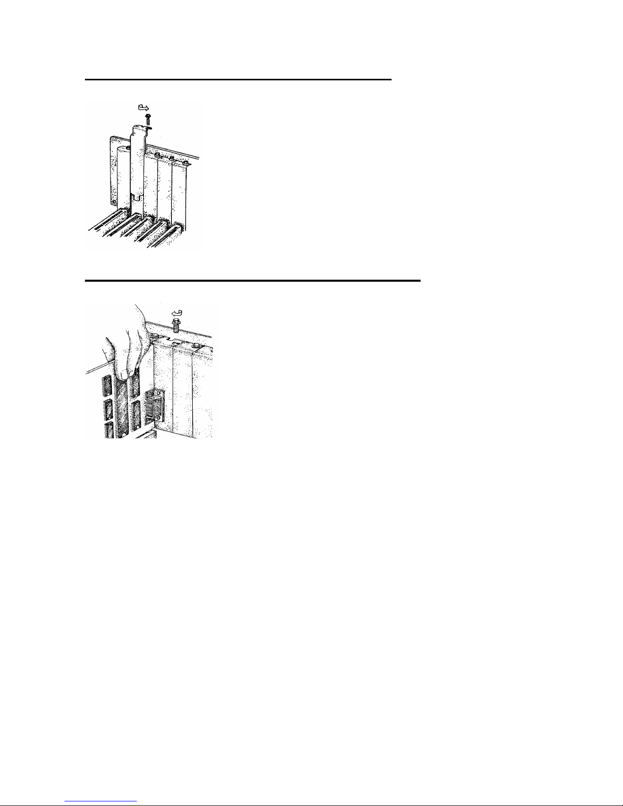
Figure 2-1. Removing Blanking Cover
STEP 3: Choose an empty appropriate
expansion slot. Remove the blanking cover
protecting the slot on the PC back panel.
KEEP the blanking cover screw safely for later
(Figure 2-1).
Figure 2-2. Inserting The PC Serial Card.
STEP 4: Now insert the PC Serial card in
the available slot. Be careful to ensure that
the gold plated PCB fingers fits neatly into
the I/O expansion connector. Press down
firmly but evenly on the top of the PC Serial
card (Figure 2-2).
STEP 5: The D connectors should fit neatly through the slot’s aperture to
the outside world. NB. Use the screw kept back from the blanking cover
to screw the PC Serial retaining bracket into the PC back panel housing.
STEP 6: Now replace the system unit s cover by carefully sli di ng
it down and back over the system unit. Replace the cover
mounting screws.
STEP 7: After attaching all the monitor and keyboard cables,
power up the PC. Do not forget the mains power cable!
The PC should power on in the normal way.
Chapter 2 Page 12
Page 11

PCI Quad RS232 Installing the Card
Problems!
If the system fails to power up normally check the following.:
i.) Ensure that th e PC Serial card is installed cor r ectl y.
ii.) Ensure that other cards in the PC have not been upset.
iii.) Ensure that the power is connected and the PC is switched
ON!
n
If all these have been checked and the PC still does not
power up then there is probably a fault in the hardware. Please
contact technical support.
Chapter 2 Page 13
Page 12

PCI Quad RS232 Software Installation
CHAPTER 3
PCI QUAD SOFTWARE
INSTALLATION
Introduction.
This section describes the software installation procedure
allowing the PCI Quad RS232 to be configured within the
Windows 3.x, Windows 95/98 and Windows NT operating
systems.
The setup procedures in this chapter assume that your PC has only
COM1 present.
Configuring Ports In Windows 3.x
The Windows 3.x installation procedure consists of 2 steps after the PCI Quad
RS232 card is inserted:
1. Determining the resources that the PCI Quad RS232 has
claimed.
2. Infor ming Windows 3.x of those resources.
Determining PCI Quad RS232 Resources.
• Insert card into PC, as described in Chapter 2.
• If you are installing from floppy disk run BBCARDS.EXE,
from the supplied DOS driver disk titled "Serial Solutions
Utility Disk" by typing the following:
HVMZI"@4'-@&&'%6(7
• If you are installing from the Serial Solutions CDROM the path
will be
HVMZI"@HMWOMQK@WWYXMP@TGM@FFGEVHW
Where
the following (values contained in the string may differ in
individual PC’s due to resource availability):
HVMZI"@
BBCARDS.EXE will return a string that looks similar to
is the drive containing the supplied disk.
Chapter 3 Page 14
Page 13
PCI Quad RS232 Software Installation
GEVHMWSRFYWHIZMGIJYRGXMSR
'EVH-(!VIZMWMSR5YEH
MRXIVVYTXPMRI-65
WIXWSJGSQTEXMFPIVIKMWXIVW
7-76MWEX-3EHHVIWW**%
&EYHGPSGOGSRXVSPMWEX-3EHHVIWW**'
;VMXI\JJSVHIJEYPX\JJSV\HJSV\HJSV
LEWFIIREWWMKRIH
EVIEX
&ERO-3EHHVIWW**
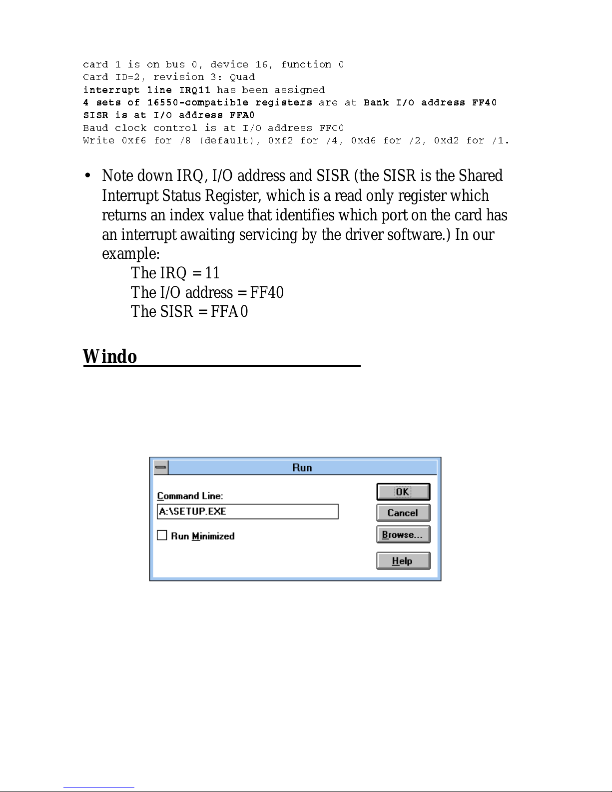
• Note down IRQ, I/O address and SISR (the SISR is the Shared
Interrupt Status Register, which is a read only register which
returns an index value that identifies which port on the card has
an interrupt awaiting servicing by the driver software.) In our
example:
The IRQ = 11
The I/O address = FF 40
The SISR = FFA0
Windows 3.x Software I nstallati on.
Place the Serial Solutions for Windows 3.x disk into a
suitable drive. From the File Menu choose ‘Run’ and enter
“a:\setup” (where a: is the path to the floppy drive with the
installation disk).
If you are installing from the Serial Solutions CDROM you will
need to insert the disk into your CDROM drive select File, Run
and type in the path <disk>:\diskimg\sswin3x\setup.exe where
<drive>:\ is the letter of your CDROM drive.
Chapter 3 Page 15
Page 14
PCI Quad RS232 Software Installation
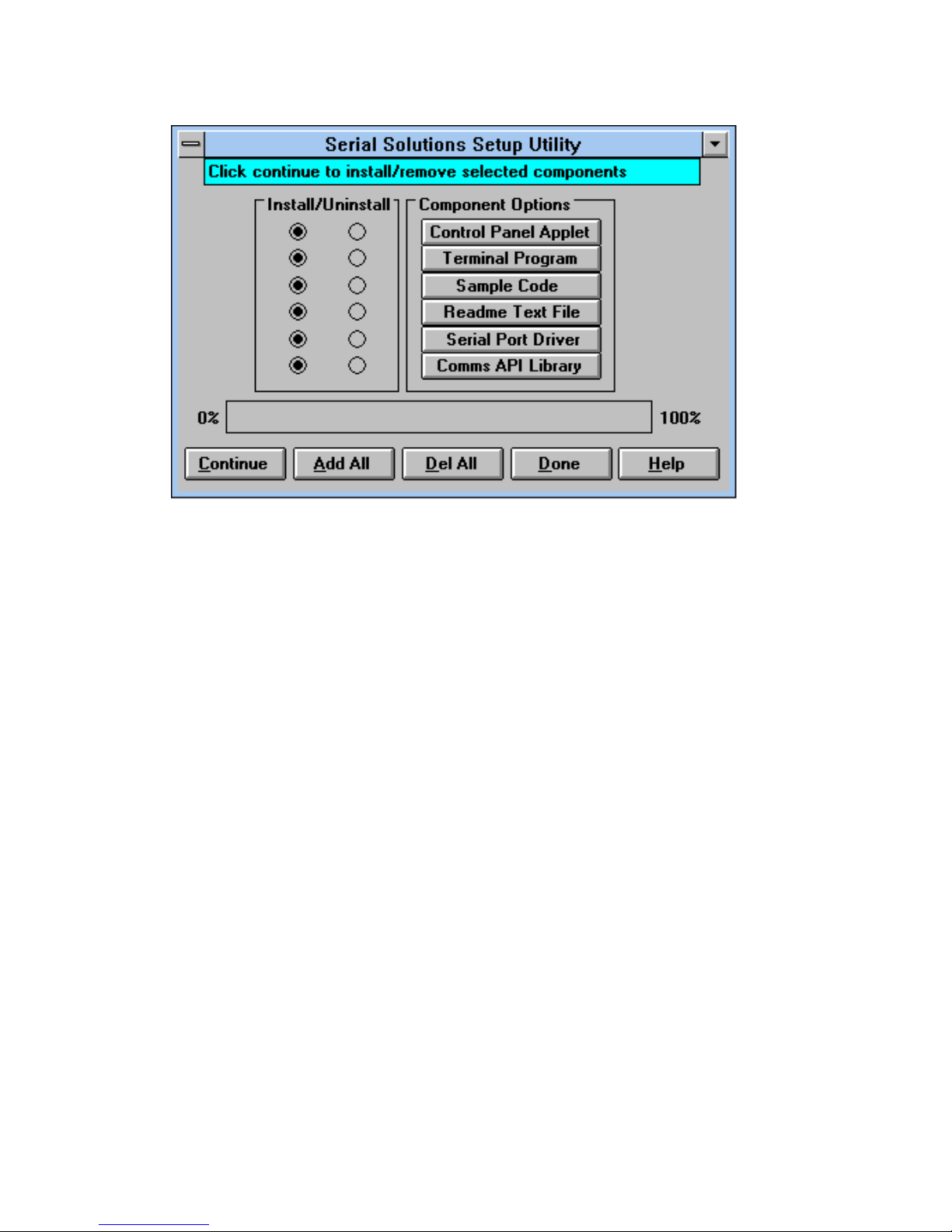
• Click OK, the Setup Program Main Screen is displayed:
By default, all component options will be installed, selecting the
"Del All" button will select all installed components for deletion
and "Add All" chooses all uninstalled components for installation;
options may not be changed when the components are installed.
For further details on the Component Options consult the
README.TXT file on the supplied disk.
If only logical ports COM1 to COM9 are to be used then
de-select the Comms API library option in the "Install" column.
This library is only necessary to allow the use of logical ports
greater than COM9 e. g. COM10, COM11 etc.
• When you have made your choice of Component Options click
Continue and when the setup program has finished select the
Done button.
Note: If the Serial Port driver option has been selected, after the
setup program has finished, Windows will display a restart
message - answer Yes and Serial Solutions will be ready to run
upon Windows restarting.
Chapter 3 Page 16
Page 15
PCI Quad RS232 Software Installation
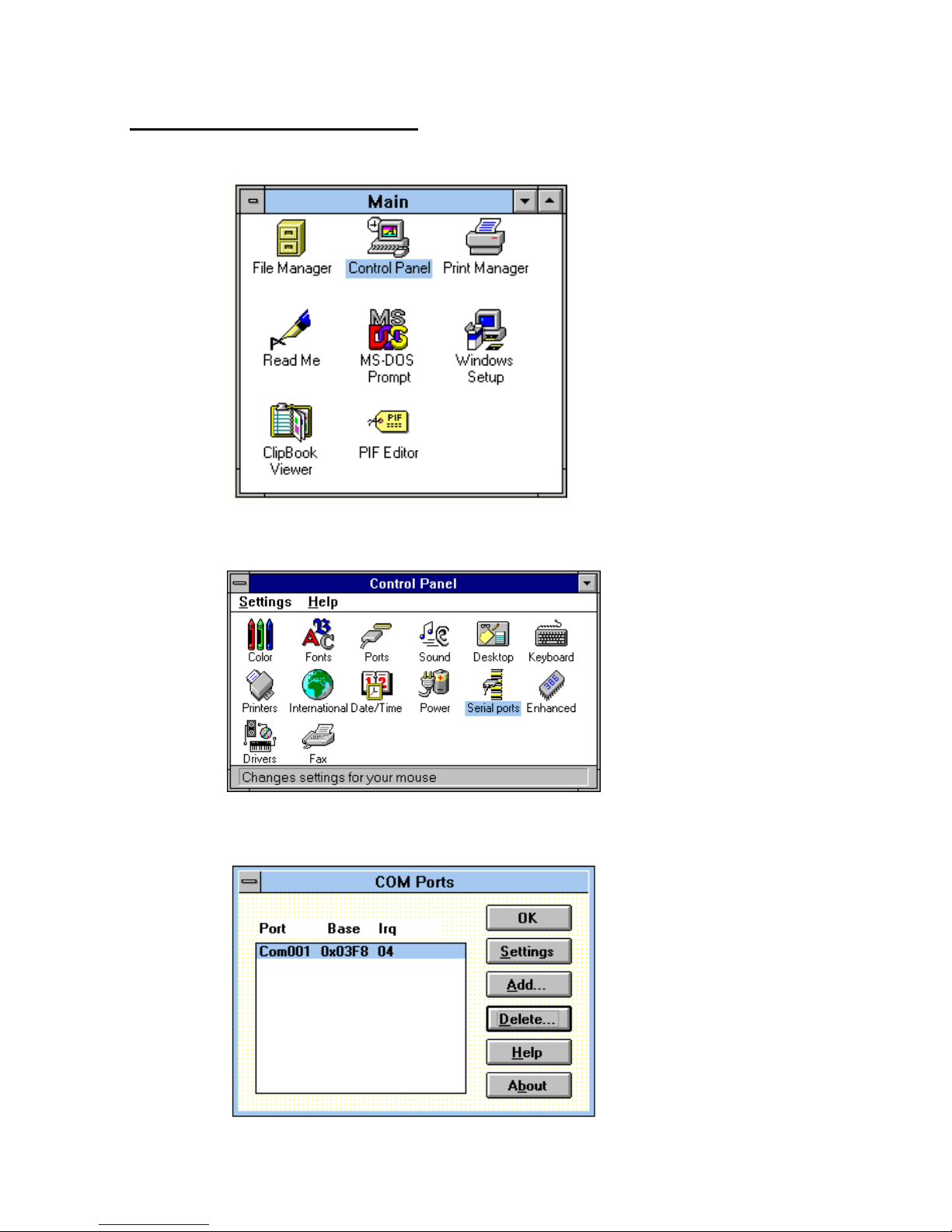
Serial Port Installation.
• From Main, select Control Panel:
• Click on Seria l Po rts:
The following dialogue will be displayed:
Chapter 3 Page 17
Page 16
PCI Quad RS232 Software Installation
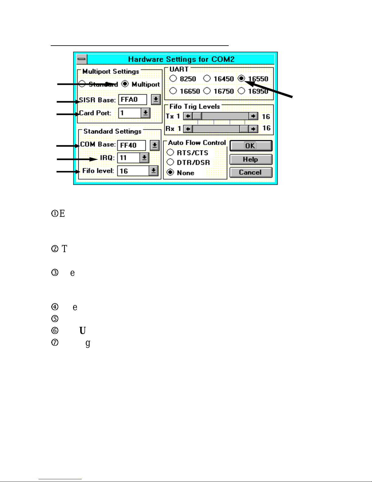
Figure 5-2. PCI Quad Serial Card Settings.
j
k
l
m
n
p
Multiport Settings:-
j
Each Port should have the Multiport button selected, this tells
Windows 3.x that the port is one of several ports using a SISR
(shared interrupt status register).
k
The SISR Base address must be set as indicated by the
BBCARDS pr o gr am .
l
The Card Po rt setting tells Windows whether this is the first,
o
second, third or fourth port of the Quad card.
Standard Settings:-
m
The COM Base is determined from the Bank Address.
n
The IRQ must be set as ind icat ed by the BBCARDS pr o gram.
o
The UART on the port is 16550 UART.
p
Having selected the 16550 you can then set the FIFO leve l at
16 bytes.
Chapter 3 Page 18
Page 17
PCI Quad RS232 Software Installation
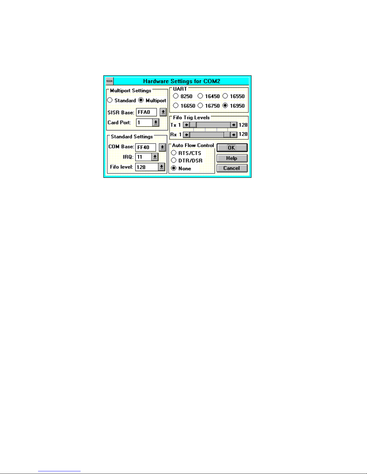
To add a COM port:
• Click on the add button and a Window similar to the following
will be displayed:
• In Multiport Settings:
• Select the Multiport radio button.
• In SISR base box, enter a SISR value of 0104 (this
value was retu r ned by the BBCARDS program, as
described in the above section.)
• In the Card’s Port field enter a value of 1, as this is the
first port of the PCI Quad RS232 to be installed.
• In Standard Settings:
• In the COM Base field, enter the value 0140 (this value
was return ed b y t he BBCARDS pr og r am , as d escr i bed
in the above section.)
Note: COM ports are defined with an i/o address range,
which in this case begins at 0140, and all subsequent
ports have an i/o address that is 8 higher than the
previous. i.e. if COM2(Port1) has an address of 0140h,
then COM3(Port2) will have an address of 0148h,
COM4(port3) an address of 0150h etc.
• In the IRQ field, enter the value 11 (this value was
returned by the BBCARDS program, as described in
the above section.)
Chapter 3 Page 19
Page 18
PCI Quad RS232 Software Installation
• When you have finished, click on OK. A restart message will
be displayed; to save time only restart when all four ports have
been added and correctly configured.
• Repeat the above process to add the next 3 COM ports of the
PCI Quad RS232 . For example, for the second port of the PCI
Quad RS232 (designated COM3) the SISR value of 0104 will
remain the same, the Card’s Port value will be 2 (the second
port of the Quad RS232 card), COM base will be 0148 and the
IRQ value is 11. After adding the remaining COM ports the
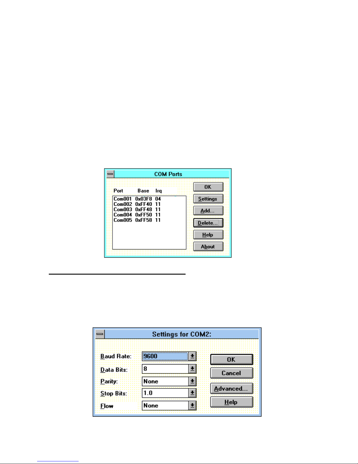
COM Ports Window will look similar to the following:
Conf iguri ng The CO M Ports.
• From the COM Ports window choose the port that you wish to
configure and click on Settings - the following dialogue will
be displayed:
Note: A port that has been added has the default values of:
Chapter 3 Page 20
Page 19

PCI Quad RS232 Software Installation
Baud Rate: 9600
Data Bits: 8
Parity: None
Stop Bits: 1.0
Flow: None:
Change the communications Settings in the COM Ports to
match the baud rate, parity settings etc. of the remote serial device.
Deleting Ports in Wind ows.
The Delete button can be used to discard the entries of
ports that have been removed from the system.
Note: Never try to leave out a serial port number when using the
delete button, because Windows may automatically shift serial port
numbers which results in a mis-match of settings in the Serial
Ports Applet (COM1-COM4 only).
Res tarting W indows .
Whenever certain values have been enter ed or changed in the
hardware settings window, a message prompting to restart
Windows will appear. Only after having made ALL the necessary
changes restart Windows so that the new settings come into effect.
Warning
Due to the nature of ‘Plug and Play’, changes in system can lead to
changes in resources allocat ed to a ‘P & P’ device.
If you alter your system configuration in any way after installing
your PCI Quad RS232 card, you will need to run BBcards to verify
the resources all ocat ed to th at car d.
Chapter 3 Page 21
Page 20

PCI Quad RS232 Software Installation
Installing Ports In Microsoft Windows 95 & 98.
Although covering the installation of the Quad RS232 into
the Windows 95 operating system, the procedure is also valid, with
only minor differences, in the Windows 98 Operating System. The
Windows 95 environment now supports up to 255 standard serial
ports, RS232, RS422, RS485 etc.
To obtain a trouble free mix-and-match of the COM ports:
• Switch off your computer, insert your Quad RS232 card into a
free PCI slot, as described in the section "Hardware
Installation" in Chapter 2, and switch your computer on again.
• During the booting process, Windows 95 will detect Quad
RS232, but will display it simply as a "PCI CARD", and you
will briefly see a message box to this effect.
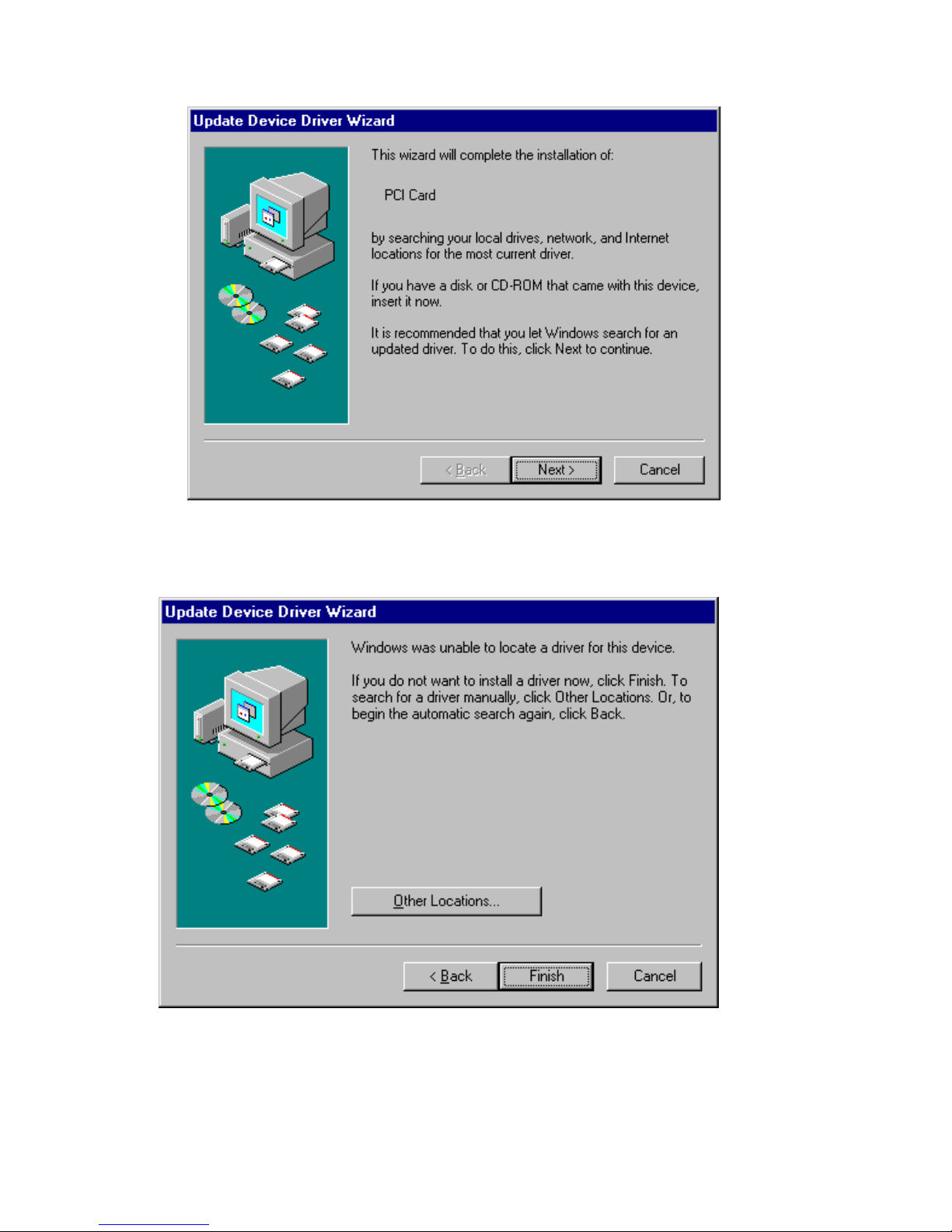
• Windows will then display the "Update Device Driver Wizard",
which asks you to “insert any disk which came with the PCI
card”. Insert the Serial Solutions CDROM into an appropriate
drive and click 'Next'.
Chapter 3 Page 22
Page 21
PCI Quad RS232 Software Installation
• The Wizard should then display something similar to following:
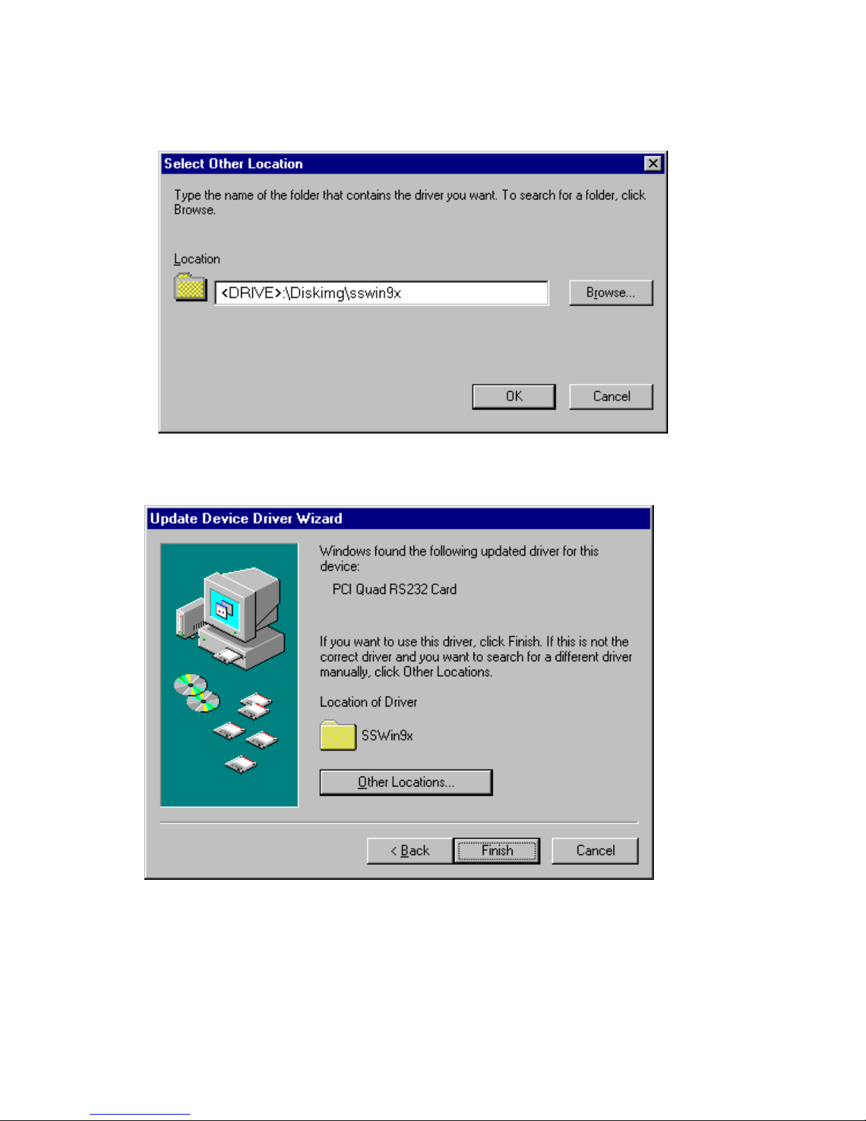
• Click Other Locations
Chapter 3 Page 23
Page 22
PCI Quad RS232 Software Installation
• Type "<Drive>:\Diskimg\SSWIN9x" Where <Drive> is the
drive letter of your CDROM drive.
• Click OK
• Click Finish
Chapter 3 Page 24
Page 23
PCI Quad RS232 Software Installation
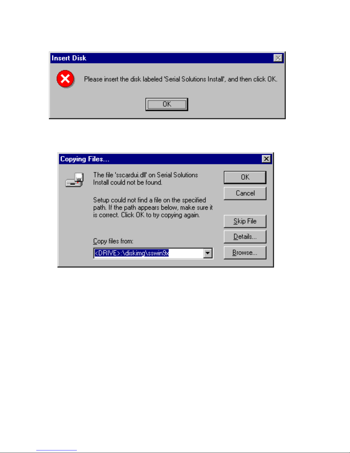
• The following dialog box will appear
• Click OK
• A "Copying Files…" window should now appear. In the Path
type "<Drive>:\Diskimg\SSWIN9x" Where <Drive> is the
drive letter of your CDROM drive.
• Click OK
• After copying the file, Windows 95 will then detect each of the
serial ports in turn and install them as communications ports it
will also detect the parallel port, and then install it as a printer
port.
Chapter 3 Page 25
Page 24
PCI Quad RS232 Software Installation
Quad RS232 Card Se ttings
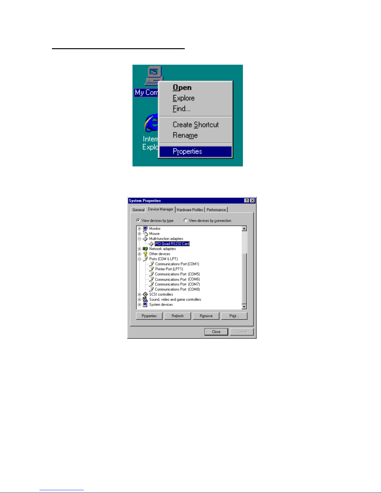
• Right Click My Computer => Properties
• Select the Device Manager Tab
• Quad RS232 will appear under the "Multi-function adapters"
branch, two Communications Ports and a Printer Port will
appear under the "Ports (COM & LPT) branch."
For most users who have 4 or less COM ports the new
ports will appear as COM5 and COM6, as pictured below; for
users with more than 5 COM ports the new ports will appear as the
first available COM ports.
Chapter 3 Page 26
Page 25
PCI Quad RS232 Software Installation
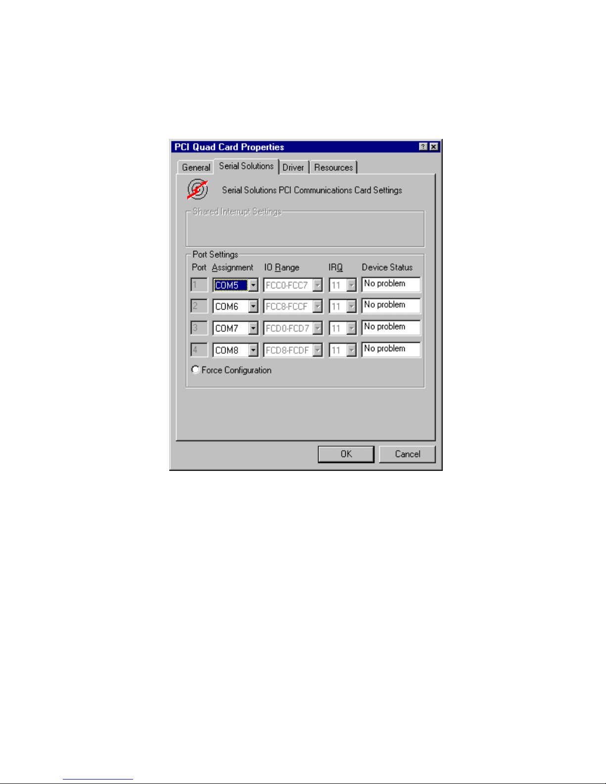
• Select the Quad RS232 card from the "Multi-Function
Adapter" entry in Device Manager and click on properties to
view the cards general properties; clicking on the Serial
Solutions tab produces:
In this window, the COM (and LPT) port assignment may
be changed, simply by selecting a new COM port value from the
pull down menu relevant to the port. However, COM port usage
other than those fo r the Quad RS232 card itself are not checked, so
it is advisable to first check which COM ports are in use - port
availability can be checked by viewing the Device Manager.
Chapter 3 Page 27
Page 26
PCI Quad RS232 Software Installation
Quad RS232 Port Sett ings
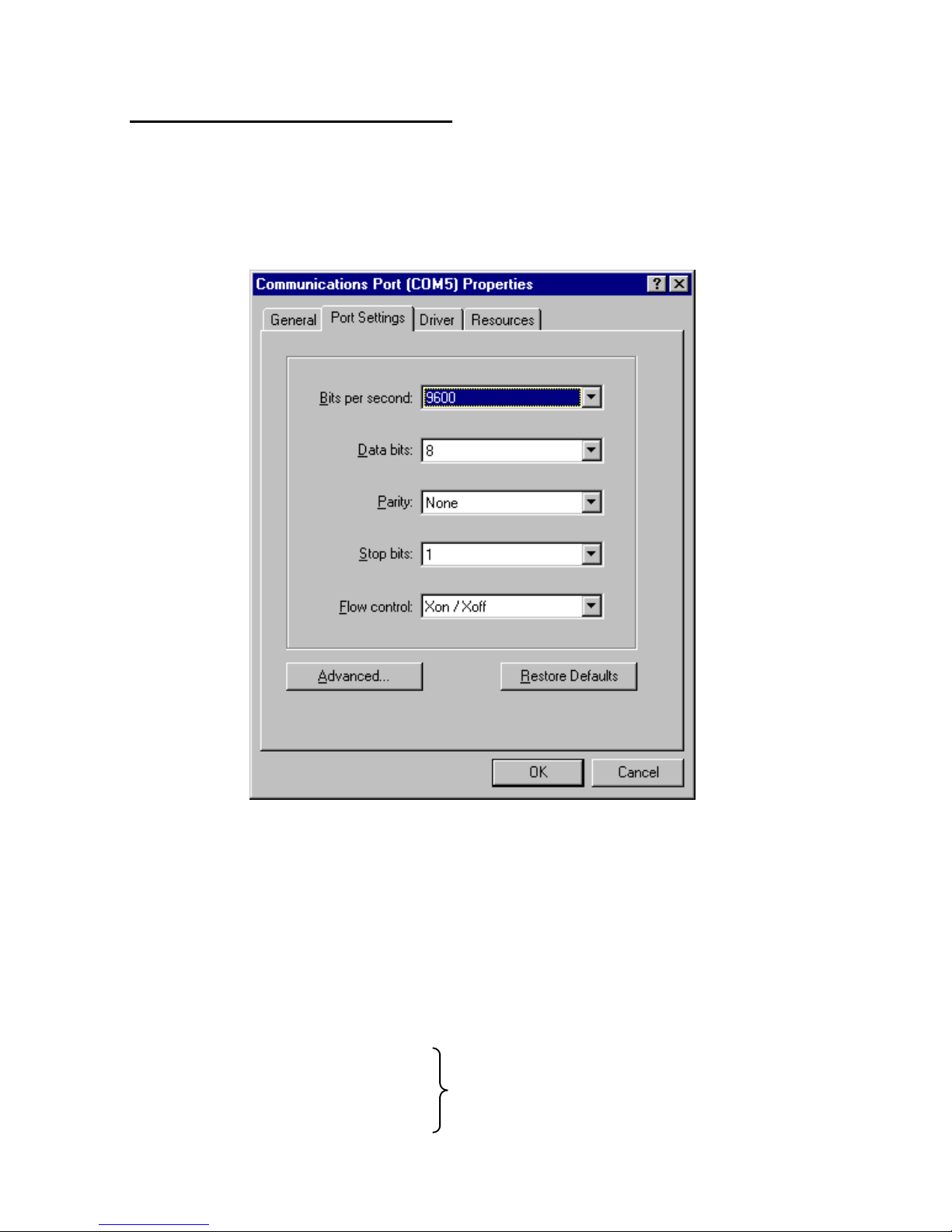
Double clicking on a Communications Port that belongs to
a Quad RS232 card will display general properties window for that
port (in this case COM5). Selecting the Port Settings tab
produces:
Settings available in these windows are:
1. Baud Rate - determines the baud rate at which the
selected port operates.
• The maximum value of operation is 115,200, even
though the maximum value selectable is 921,600 this is due to standard Windows COM port drivers
being used.
2. Data Bits.
3. Parity.
4. Stop Bits.
Change to suit remote device.
Chapter 3 Page 28
Page 27
PCI Quad RS232 Software Installation
5. Flow Con trol.
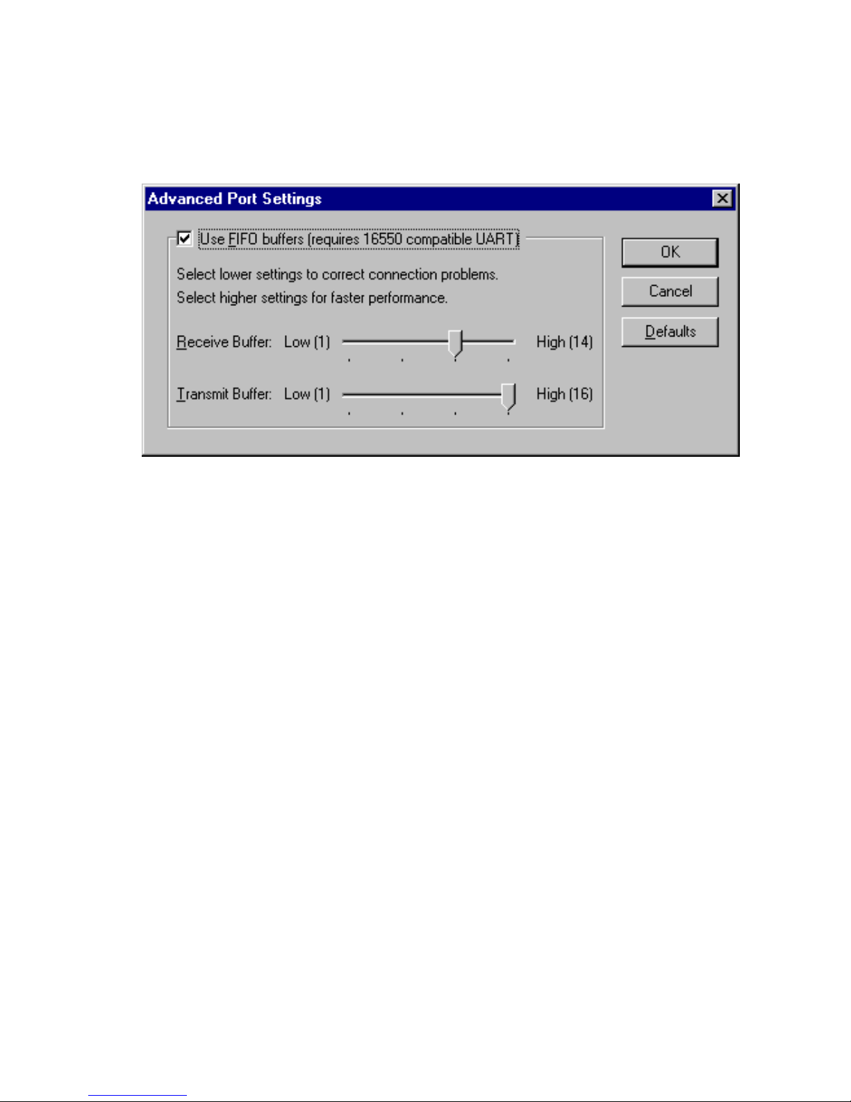
6. Advanced - clicking on this will display the following
window:
Settings available in this window are:
• Use FIFO Buffers - turns the selected ports FIFO
buffer on or off. It is strongly recommended that the
FIFO for both ports is left enabled.
• Receive Buffer - These settings allow the selection
of a receiver FIFO trigger setting. Selecting a low
value will allow the interrupt to be serviced quicker,
which is good for slow machines. If you have a fast
machine, setting a high value will give you more
time for multi-tasking operations.
• Transmit Buffer - These settings allow the
selection of a transmitter FIFO trigger setting.
Selecting a low value will send fewer data-bytes per
interrupt, and this is recommended if you are
communicating to a slower machine. Selecting a
high value will send more data-bytes per interrupt,
and will give more time for multi-tasking
operations.
Chapter 3 Page 29
Page 28

PCI Quad RS232 Software Installation
• Defaults: when clicked this button restores the
advanced settings for t he select ed por t to:
Use FI FO Buffers: On (Checked)
Receive Buffer: High (14)
Transmit Buffer: High (14)
7. Restore Defaults - when clicked, resets the selected
COM port to the following values:
Baud Rate: 9600
Data Bits: 8
Parity: None
Stop Bits: 1
Flow Control: Xon / Xoff
Chapter 3 Page 30
Page 29
PCI Quad RS232 Software Installation
Configuring Ports In Microsoft Windows NT 4.0
Microsoft Windows NT Provides built in support for 255
standard serial ports. To setup your Quad RS232 serial card you
should follow these steps. Please note that to change any kind of
hardware configuration under Windows NT you must be logged in
as a user with Administrator level privileges, if you do not have
these please contact your system administrator.
Software Installation.
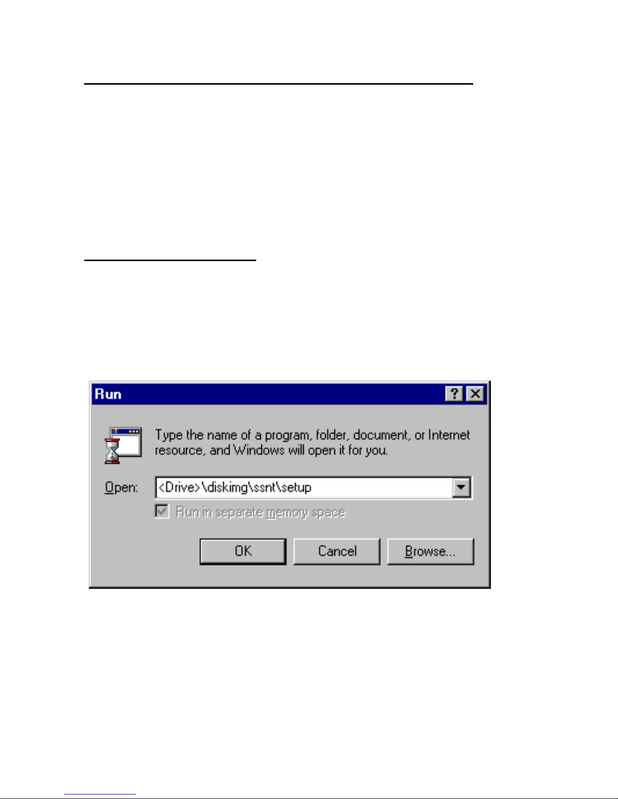
Insert the Quad RS232 into your PC, as described in
chapter 2, and restart. Place the supplied Serial Solutions CDROM
in a suitable drive and from the Start Menu choose Run and enter
<Drive>:\diskimg\ssnt\setup (where <Drive> is the
Drive Letter of your CDROM drive).
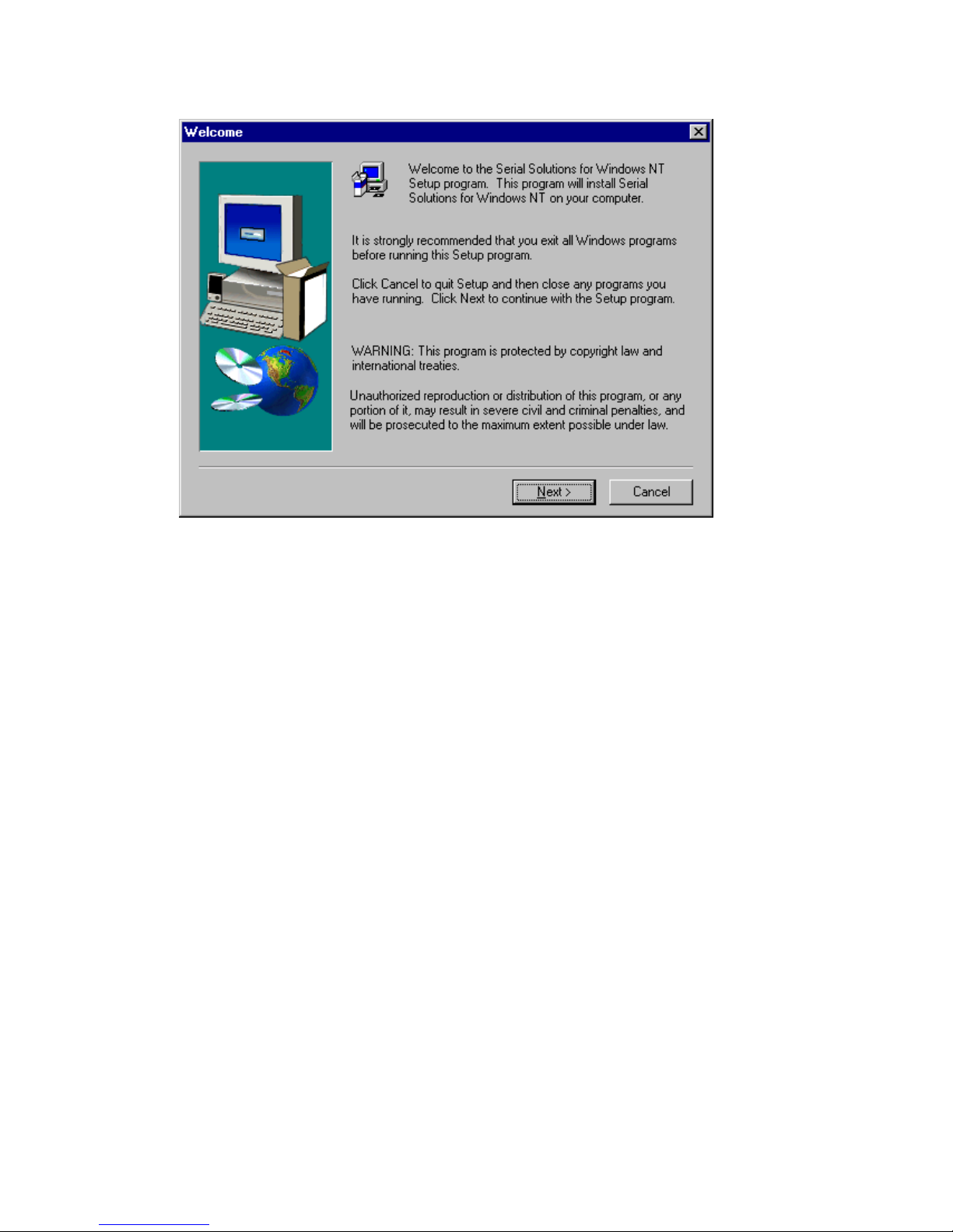
• You will be then see the SSNT splash screen followed
by am welcome screen
Chapter 3 Page 31
Page 30
PCI Quad RS232 Software Installation
• Click Next.
• Installshield will then complete the software
installation
Chapter 3 Page 32
Page 31
PCI Quad RS232 Software Installation
Examining Card Configuration.
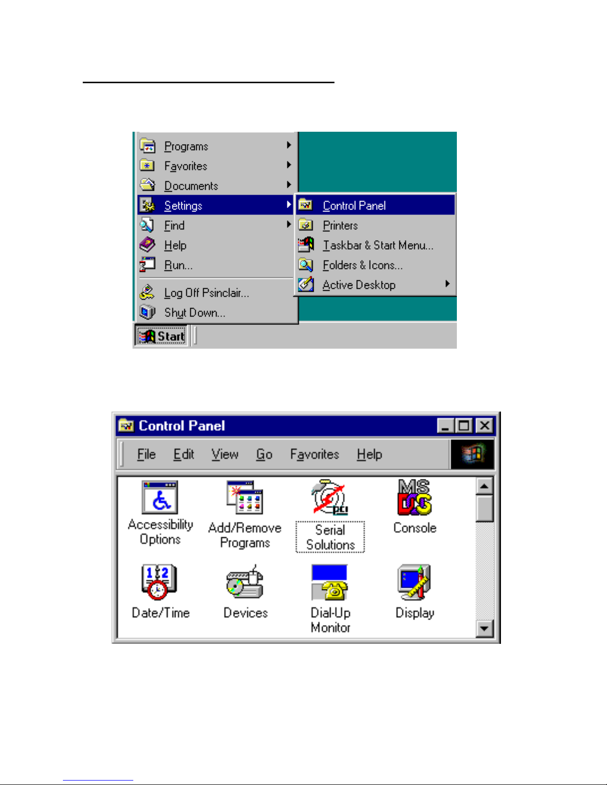
Go to Control Panel (Start/Settings/Control Panel)
• Double Click Serial Solutions
Chapter 3 Page 33
Page 32
PCI Quad RS232 Software Installation
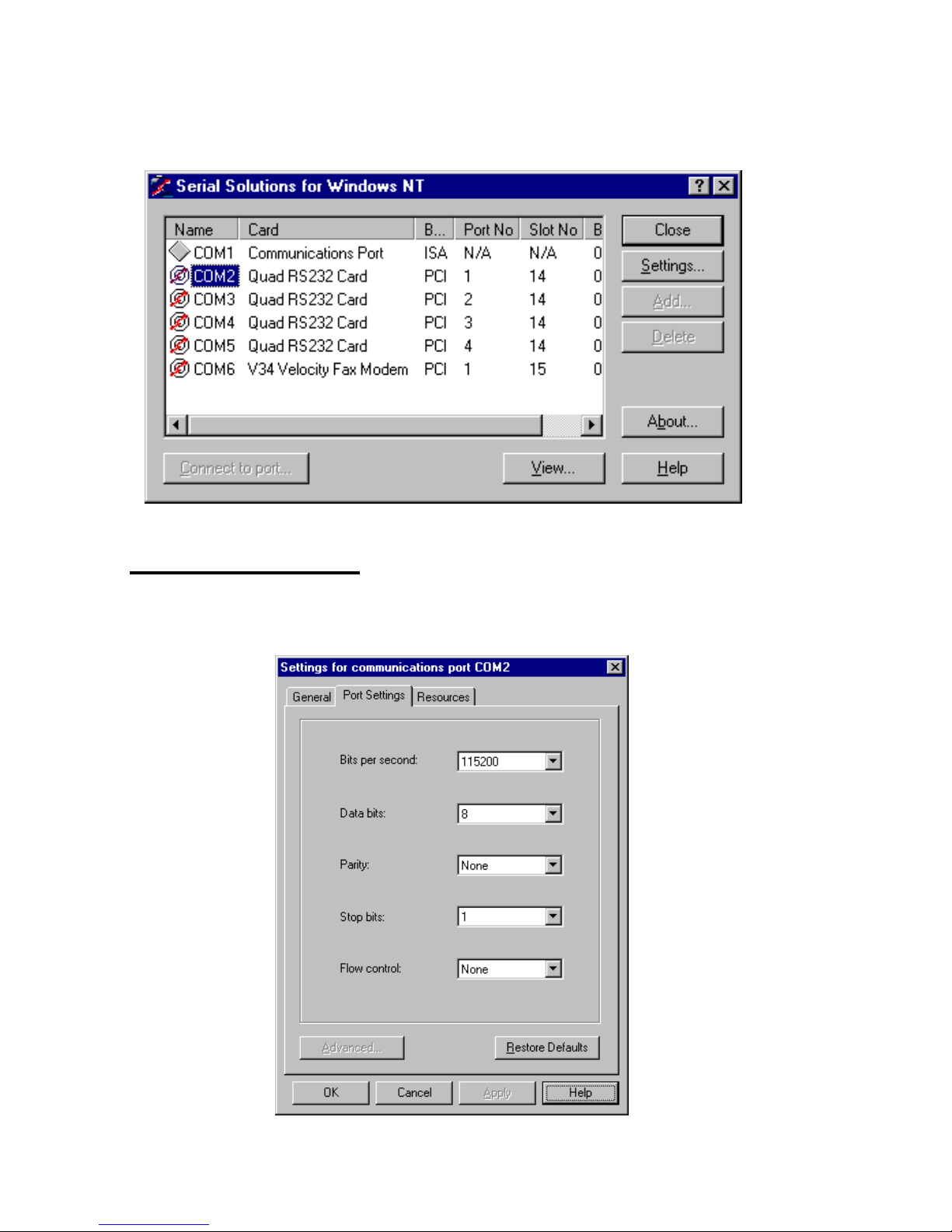
You will be presented with a Serial Solutions PCI Port
Configuration window:
Conf iguri ng Ports.
To view the settings of a port, select it and click on
settings, and then click on the resources tab:
Chapter 3 Page 34
Page 33

PCI Quad RS232 Software Installation
Settings available in this window are:
1. Baud Rate - determines the baud rate at which the
selected port operates.
• The maximum baud rate available is 115,200.
2. Data Bits.
3. Parity.
Change to suit remote device.
4. Stop Bits.
5. Flow Contro l.
6. Advanced - see the section below, titled "Advanced
Port Settings."
7. Restore Defaults - when clicked, resets the selected
COM port to the following values:
Baud Rate: 9600
Data Bits: 8
Parity: None
Stop Bits: 1
Flow Control: Hardware
Uninstalling Serial Solutions PCI.
To uninstall Serial Solutions PCI:
• From Control Panel, open the Add/Remove Programs applet,
then close the Control Panel.
• Select from the list Serial Solutions PCI.
• Click the Add/Remove button.
Windows NT will then uninstall the Serial Solutions PCI applet
without the need for restarting.
Chapter 3 Page 35
Page 34
PCI Quad RS232 DOS Installation
CHAPTER 4
PCI QUAD DOS INSTALLATION
PROCEDURE
Determining PCI Quad Resources.
• Insert the card into a PC, as described in Chapter 2, power up
the PC
• From DOS Run BBCARDS. E XE , Found on the Serial
Solutions CDROM, by typing the following:
<drive:>\diskimg\ssutil\pci\bbcards
• If you are installing from floppy disk then the path will be
<drive:>\pci\bbcards
Where <drive>is the dr i ve containing the suppl ied disk.e. g . a:\
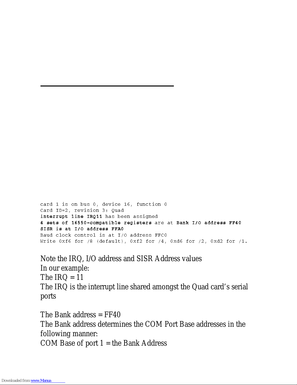
BBCARDS.EXE will display a message that looks similar
to the following ( the values displayed may differ due to resource
availability):
GEVHMWSRFYWHIZMGIJYRGXMSR
'EVH-(!VIZMWMSR5YEH
MRXIVVYTXPMRI-65
WIXWSJGSQTEXMFPIVIKMWXIVW
7-76MWEX-3EHHVIWW**%
&EYHGPSGOGSRXVSPMWEX-3EHHVIWW**'
;VMXI\JJSVHIJEYPX\JJSV\HJSV\HJSV
LEWFIIREWWMKRIH
EVIEX
&ERO-3EHHVIWW**
Note the IRQ, I/O address and SISR Address values
In our example:
The IRQ = 11
The IRQ is the interrupt line shared amongst the Quad card’s serial
ports
The Bank address = FF40
The Bank ad dress deter m in es t h e COM P o r t Base add r esses in th e
following manner:
COM Base of port 1 = the Bank Address
Chapter 4 Page 36
Page 35

PCI Quad RS232 DOS Installation
COM Base of port 2 = the Bank Address + 8hex
COM Base of port 3 = the Bank Address + 10hex
COM Base of port 4 = the Bank Address + 18hex
The SISR Address = FFA0
The SISR Address is th e Sh ar ed Interr upt Status Regi ster, this is a
read-only register indicating which of the four serial ports requires
service by the driver software.
These values will be required when setting up the Newcom.sys
DOS device driver
Informing The PC Of The Port Address.
If using Serial Solutions driver Newcom.sys this section should
be ignored.
The BIOS of most new PC’s automatically detect s whet her ser ial
ports COM1 - COM4 addresses ar e pr esent in a machi ne. Other ,
older PC’s are capable of detectin g serial por t s COM1 - COM2,
but the problem comes with serial ports COM3 and COM4. PC's
have a table of information that stores the setup of the PC, this is
the BIOS data ar ea. It has space fo r 4 serial port addr esses. The
trick, for the older PC’s, is to get the right addresses into the third
and fourth port areas. However, PC’s are not capable of
recognising ports above COM4 - specific device drivers are
responsible for this.
On the utility disk included with your card there are several
programs for set t i n g t h e COM3 and CO M4 ad d resses. To set
COM3 address from the DOS command line enter:-
ADDRCOM3 03E8 <return>
To set COM4 address from the DOS command line enter:-
ADDRCOM4 02E8 <return>
To set the COM port address from within the
Chapter 4 Page 37
Page 36

PCI Quad RS232 DOS Installation
AUTOEXEC.BAT file use a text editor to add the following lines
to the file:-
ADDRCOM3 03E8
ADDRCOM4 02E8
DOS 4, 5 and DOS 6 have features allowing access to
COM3 and COM4. DOS 2 and DOS 3 only allowed access to
COM1 and COM2, though some manufacturers their own DOS
versions, e.g. COMPAQ, had enhanced MODE commands etc. to
set up and use the extra ports.
If you are uncertain how many serial and parallel ports are
in the machine, it is wise to run the ADDRCOM3 program
BEFORE installing an AT Quad RS232 series card type: -
ADDRCOM3 <return>.
The PC responds with something like:-
COM1: 03F8
COM2: 02F8
COM3: <not set >
COM4: <not set >
LPT1: 03BC
LPT2: <not set>
LPT3: <not set>
If the RS232 installation is attacked in this orderly manner,
every thing should work first time. If it does not then check the
software selectable communications parameters, Baud rate, Parity,
stop bits first, and that the communications program is attempting
to access the serial por t i nst al led. I f this fails to solv e th e problem
check the cable connections. F inal ly check that the car d is indeed
configured as you believed.
Chapter 4 Page 38
Page 37

PCI Quad RS232 DOS Installation
Settings for DOS Soft w ar e .
Most users will require that the IRQ is set to correspond to
the interrupt used by their serial communications software. Note,
that a serial port that is USING interrupts must not share the same
IRQ line as another serial port that is USING interrupts AT THE
SAME TIME, otherwise some interrupts will be missed. IE no two
ports may use the same IRQ line simultaneously.
Some serial comm unicat ions sof t war e, especially older
versions, assume that COM1 and COM3 both use IRQ4 and that
COM2 and COM4 both use IRQ3. Other older packages assume
that COM1 is on IRQ4 and that COM2, COM3 and COM4 all use
IRQ3. Both kinds of older packages will therefore not allow
simultaneous interrupt driven I/O on all four ports. It may be
necessary to upgrade your serial communications software.
Newer, more up to date, serial communications programs
are configurable. T hey allow the user to speci f y the I/O address
and the interrupt used by the serial port. Procomm and many other
packages are configurable in t his way.
Figure 4-1 PCI Quad as COM3-COM6
NewCOM.SYS.
DEVICE=NEWCOM.SYS /A3, FF40 /A4, FF48 /A5, FF50 /A6,
FF58 /L FFA0,7,3,4,5,6
l
l
l
l
PC already has COM1 installed on IRQ 4
PC already has COM2 installed on IRQ 3
Quad card set as Bank shared IRQ 7.
All interrupts set to Shared
On power up the PC will display the following messages:-
Serial Solutions serial port Device Driver V2.5 6th Jan 1993
Chapter 4 Page 39
Page 38

PCI Quad RS232 DOS Installation
Copyright (c) 1990 - 1993
Set address COM3 to FF40h
Set address COM4 to FF48h
Set address COM5 to FF50h
Set address COM6 to FF58h
Setup quad card, status register at FFA0th interrupt line 11
COM3 is card’s port 1
COM4 is card’s port 2
COM5 is card’s port 3
COM6 is card’s port 4
Setting number of Buffers to 10
Setting buffer size in bytes to 512
The /A switch is used to set the address of the chip used for a
particular COM: port. Thus:/A3, FF40 specifies COM3 has an I/O address of FF40
/A4, FF48 specifies COM4 has an I/O address of FF40
/A5, FF50 specifies COM5 has an I/O address of FF50
/A6, FF58 specifies COM6 has an I/O address of FF58
This is the default setting for the Quad cards port 1-4.
The /L switch is used to specify a multiport card with interrupt
sharing is in use.
The parameters specify the SISR address, the interrupt line, and
how the ports are assigned as COM ports. Thus:/L FFA0, 11, 3,4,5, 6
Specifies th at t he S h ared Int errupt Stat us Regist er , SIS R, is at I/O
address FFAO hex, that interrupt 11 is the shared interrupt line,
and that:Multiport #1 is mapped as COM3
Multiport #2 is mapped as COM4
Multiport #3 is mapped as COM5
Multiport #4 is mapped as COM56
Chapter 4 Page 40
Page 39

PCI Quad RS232 DOS Installation
The /B switch, /B 5, works as before and sets the number of
buffers to 5. The 5 buffers are 1 for the (built in) COM1: port and
one each for the 4 ports on the card.
The /S switch, /S 512, also works as before and sets the buffer size
for the 9 buffers specified. This is a 512-byte input buffer and a
512 byte output buffer. When many ports are simultaneously in
use in a PC then the larger the buffers the better especi all y at high
baud rates. This allows more time for processing the data before
any port’s buffer becomes full.
I/O Address.
Switch: /A n,add
Switch: /A n-m,add NEW
Switch: /A n-,add NEW
Purpose:
Set the I/O address of one serial port, COMn.
Sets the I/O address of several ports starting at COMn.
’n’ specifies the COM port. ’n’ must be given.
If only ’n’ is given only one ports address is set.
If ’n-m’ or ’n-’ are given then the addresses of all the ports in the
range is set starting at the I/O address ’add’.
’add’ is the address of the port, it must be in hexadecimal, and can
be optionally suffixed with an ’h’ or ’H’.
For exa mp le:
/A1,FF40 /a2,FF48H
Sets COM1 to FF40H and COM2 to FF48H.
For example:
/A3,FF40 /A4,FF48 /A5,FF50 /A6,FF58
Is used with the card to set the I/O address of the serial ports. The
above line specifies COM3 to COM6, port#2-5 on the card. The
built in COM1 port on the PC and the port#1 will both be found by
the PC’s BIOS on power up since they are at the default COM1
and COM2 addresses.
Chapter 4 Page 41
Page 40

PCI Quad RS232 DOS Installation
Number Buffers.
Switch: /B n
Purpo se:
Set number of pairs of buffers to set up.
n is in range 0 to 16 and is the number of buffers to allocate. This
is one factor which sets the maximum number of serial ports that
can be used in interrupt mode. NewCOM reserv es space f or t he
buffers from main memory when the machine is booted.
For example:
/B 5
Reserves 5 buffers, one for the built in COM1 port and one each
for the 4 ports on the card.
For example:
/B 4
Reserves space for four pairs of buffers, enough for four serial
ports. The default is six pairs. The buffer allocated contains an
equal amount of room for both the incoming data and the outgoing
data.
Hardware Handshake.
Switch: /H [n],[hs ]
Purpose:
Select which hardware handshake type to use on port COMn.
’n’ specifies the COM port. If n is not specified the handshake is
applied to all serial ports.
’hs’ is a number indicating the type of handshake, and 0 is the
default. This does not override a previous XON/XOFF setting, in
conjunction with which it may be used. The types are listed below
and detailed under ’hardware handshakes’ later.
For example:
/H1,2 Set COM1, handshake 2
Chapter 4 Page 42
Page 41

PCI Quad RS232 DOS Installation
/H,1 Set handshake 1 for all ports
The /H switches are processed from left to right, so for example
/H,2 /H1,0 /H2,1 would set COM3 to COM16 to handshake mode
2, COM1 to mode 0 and COM2 to mode 1.
The hardware handshakes currently supported are:
Type 0 RS232 DTR/CTS
Type 1 RS422 RTS/CTS
Type 2 RS485 Half duplex
Type 3 RS485 Send only.
Type 4 No handshake used, only TxD, RxD and Gnd need be
connected.
Hardware Interrupt.
Switch: /I n,i
Purpose:
Set interrupt lines for COMn.
’n’ specifies the COM port. If n is not specified the interrupt line is
applied to all ports.
’i’ is the interrupt line in the range 2 to 7 and 10 to 15 or, to
indicate no interrupt line, -1 or nothing.
For example:
/I1,4 set COM1 to use line 4
/i,-1 sets all ports to no interrupt
/i2, sets COM2 to no interrupt
The /I switches are processed from left to right, so for example
/I,3 /I1,4 sets COM1 to line 4 and COM2 to COM16 to line 3.
A serial port must be assigned an interrupt line before it can be
used. On PC/XT/AT machines and EISA bus machines only one
serial port can use an interr upt line. On PS/2 machin es ser ial ports
can share interr upts. Multi por t car ds with special int errupt
hardware have different rules- see the information for setting up
those cards.
Chapter 4 Page 43
Page 42

PCI Quad RS232 DOS Installation
When allocating interrupt lines to serial ports note that the
six IRQ lines available t o PC cards are tradit ional ly designat ed as
follows:
IRQ 2 Usually Free.
IRQ 3 COM2, COM3 , COM4 etc.
IRQ 4 COM1
IRQ 5 LPT2:
IRQ 6 Floppy disk
IRQ 7 LPT1
IRQ 10 Usually Free.
IRQ 11 Usually Free.
IRQ 12 Usually Free.
IRQ 15 Usually Free.
4 Port RS232 cards
Switch: /L add,i,p1,p2...
Purpose:
Set up one or more cards. This command is entirely equivalent
with the /D command with which it is interchangeable.
’add’ is the address of the Shared Interrupt Status Register, SISR,
set on the card.
’i’ is the interrupt line set on the Shared IRQ jumper block.
’p1’, ’p2, etc. are t he COM port all ocati on for the car d. For example
if p1 is ’3’, then port 1 on the card will be accessed as COM3. The
COM3 I/O address, ie t he address of th e car d port#1, i s specif i ed
elsewhere on the CONFIG.SYS file line, using the /A3 switch. The
’p’ places can be empty, indicating t hose ports on the card that are
not being set up to use the shared interrupt mechanism.
For example:
/L FFAO,11,2,3,4,5,6,7,8,9
Specifies th at t he S h ared Int errupt Stat us Regist er , SIS R, is at I/O
address FFA0 hex, that interrupt 11 is the shared interrupt line, and
Chapter 4 Page 44
Page 43

PCI Quad RS232 DOS Installation
that:-
port#1 is mapped as COM2
port#2 is mapped as COM3
port#3 is mapped as COM4
port#4 is mapped as COM5
For example:
/L 300,7,3,4,5,6
sets up a card with a status register at 0300H. The card uses
interrupt 7 as the shared i nterrupt line. Por t s 1 and 2 are designated
as COM3 and COM4, Ports 3 and 4 are designated COM5 and
COM6, and all the shared interrupt IRQ 7.
Multiple cards can be installed separately, each card using its own
status registers and interrupts. Note that although linked cards can
share interrupts, separate cards cannot share any interrupt line.
/L 0120,7,3,4,5,6 1st card SISR at 0120
/L 0300,10,7,8,9,10 2nd card SISR at 0300
The interrupt line specified in the /L switch overrides any
interrupt s set vi a t he /I switch for the sam e COM por t s, because
cards use a slightly differ ent mechani sm f or interrupt s.
Buffer Size.
Switch: /S n
Purpose:
Set size of all buffers in bytes. n is rounded to the nearest power of
2, and must be in the range 32 to 32768. For any serial port opened
two buffers of size n are allocated, one for input and the other for
output. The space for the buffers is reserved by th e driver when the
machine is booted. For example:
/S 512
sets the buffer size to 512 bytes. The default size is 256 bytes.
Note that in actual operation only n-1 bytes are available, so the
default buffer, nominally 256 bytes long, can only hold 255 bytes.
Chapter 4 Page 45
Page 44

PCI Quad RS232 DOS Installation
Software Handshaking.
Switch: /X n[,xon,xoff]
Purpose:
Set port COMn to XON/XOFF handshaking. In this mode the
hardware handshake lines are ignored and the characters XON and
XOFF are used to control the flow of characters on th e serial lin e.
The optional parameters XON and XOFF are decimal numbers
which are to be used as the XON and XOFF characters. Their
default values are 17 (DC1) and 19 (DC3) respectively. For
example:
/X2 or /X3,18,20
If n, the port number, is not given, then XON/XOFF handshaking
and any specified handshake character s ar e set f o r all ports, as
/X or /X,18,20
Driver Defaults.
When no switches are specified i n t he CONFIG. S YS file
the following defaults are used:
I/O Add resses.
On PC/XT/AT machines t he ROM BIOS checks for COM1 and
COM2 at their usual I/O addresses (03F8H and 02F8H
respectively), and so these ports are automatically recognised. If a
port is present at 02F8H only then this becomes COM1. IBM PS/2
machines recognise the first 4 serial ports are automatically.
Interrupt Lines.
COM 1- 4
COM 2- 3
COM 8- -1 (meaning none set)
Multiport Cards.
No multiport cards are assum ed to be present.
Chapter 4 Page 46
Page 45

PCI Quad RS232 DOS Installation
Hardware Handshake.
All ports default to H0, the DTR/CTS handshake used by RS232
systems.
Software Handshake.
XON/XOFF handshaking is disabled and the characters are
XON=17, XOFF=19, should software handshaking be turned on.
Buffer Size.
Buffers are 256 bytes long.
Bu ffer Numb er.
The maximum number of pairs of buffers is 6 (that is up to six
ports can use buffered I/O).
Baud rate etc.
These depend on a variety of factors. Ports recognised by the ROM
BIOS are reset to 2400 Baud, no parity, 8 data bits and one stop bit
when the machine is powered up. The other ports reset to no
parity, 5 data bits and one stop bit via the chip reset. They maintain
their baud rates over a reboot, but tend to loose them if the
machine is switched off, when they reset to approximately 1.8
Baud.
Bu ffer enabli ng.
When the machine is rebooted all buffers are deallocated. When a
port is first used its buffers are allocated and enabled.
Chapter 4 Page 47
Page 46

PCI Quad RS232 RS232 Pinouts & Cabling
CHAPTER 5
RS232 PINOUTS AND PORT
CABLING.
Introduction.
This chapter gives details of the 9 and 25 pin RS232 pin outs,
cabling and connections, with information on how to connect the
serial ports of two PCs, how to make a selftest loop back connector
and the pinouts of the Quad RS232 cards.
The RS232 Standard.
The RS232 standard is ancient in computer industry terms.
Introduced in 1962, it is now widely established. RS232 is a slow
speed, short distance, single ended transmission system (i.e. only
one wire per signal). Typical RS232 maximum cable length is 50
feet with a maximum data rate of 20K bits per second.
Figure 5-1. RS232 Point T o Point Connection.
DTTL
TTLR
Ground Ground
Line Length Max Data Rate
50 Feet = 15m 20 Kbits/sec
RS232C Standard
1 Driver 1 Receiver
Chapter 5 Page 48
Page 47
PCI Quad RS232 RS232 Pinouts & Cabling
)
Serial Port Pin Outs.
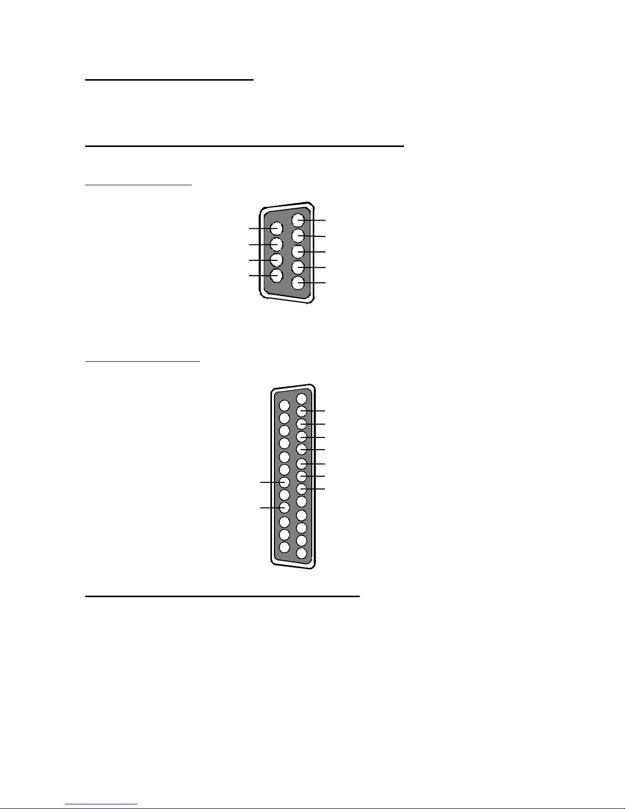
The pinouts of the 9 & 25 pin Male D connectors are given below.
Figure 5-2. Serial Port RS232 Pi n Outs.
9 Pin connector:
PIN 6 - DATA SET READY (DSR)
PIN 7 - REQUEST TO SEND (RTS)
PIN 8 - CLEAR TO SEND (CTS)
PIN 9 - RING INDICATOR (RI)
25 Pin connector:
PIN 20 - RING INDICATOR (RI)
PIN 22 - DATA TERMINAL READY (DTR)
PIN 1 - DATA CARRIER DETECT (DCD)
PIN 2 - RECEIVED DATA (RXD)
PIN 3 - TRANSMITTED DATA (TXD)
PIN 4 - DATA TERMINAL READY (DTR
PIN 5 - GROUND (GND)
PIN 2 - TRANSMITTED DATA (TXD)
PIN 3 - RECEIVED DATA (RXD)
PIN 4 - REQUEST TO SEND (RXD)
PIN 5 - CLEAR TO SEND (CTS)
PIN 6 - DATA SET READY (DSR)
PIN 7 - GROUND (GND)
PIN 8 - DATA CARRIER DETECT (DCD)
9 Pin D Serial Port RS232 Cables.
To connect to the AT style RS232 Serial Port you will need a
cable terminating in a 9 way female D connector. It is sound
practice to use cables with screws fitted that will allow you to
fasten the cable secur ely to th e PC card.
In general, you will need to make up a "cross over" cable to
correctly interface the P C to the RS232 port of another computer
or device. Traditionally, making up the cross over cable has been
Chapter 5 Page 49
Page 48

PCI Quad RS232 RS232 Pinouts & Cabling
considered a black art. However, provided you have the pin outs
and handshake requirements of both sides of your RS232
connection, the cross over cable becomes a m att er of common
sense. The cross over cable is simply to ensure that the right
signals going out of one RS232 port go into the appropriate lines
of the other RS232 port.
9 Pin D Serial Port Connection To Anot her PC.
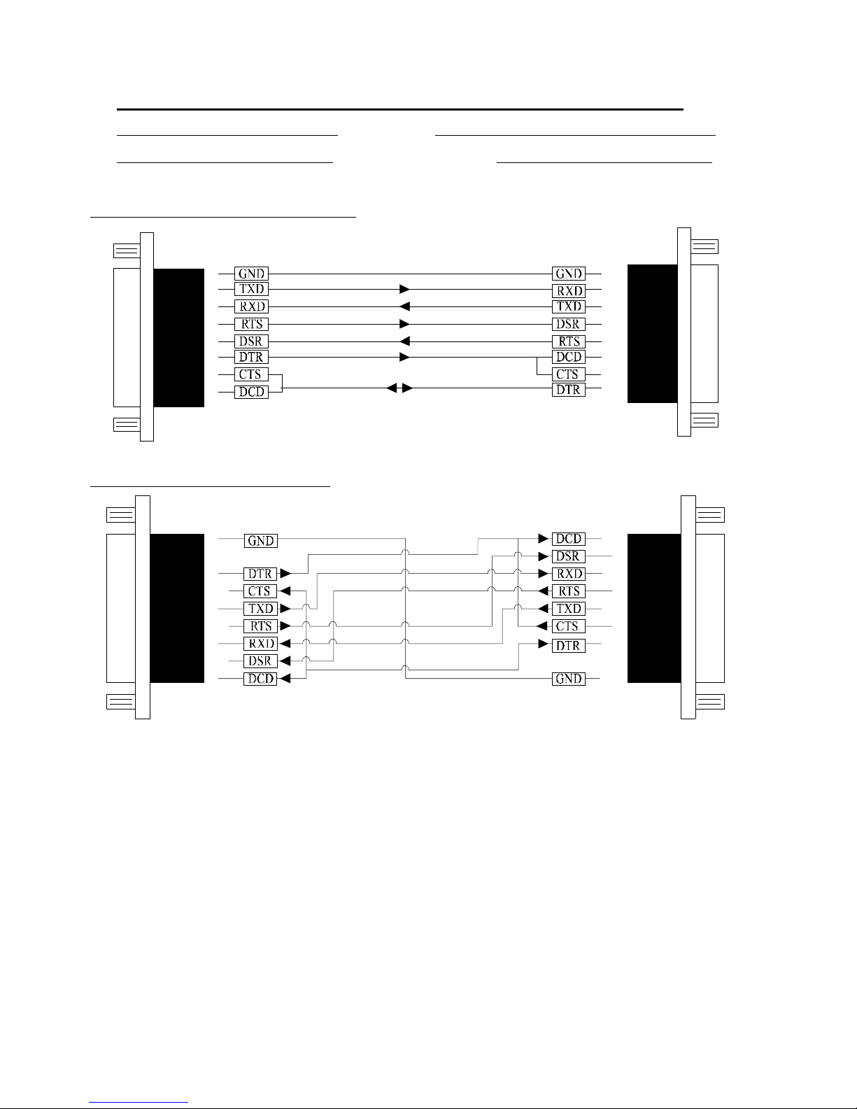
Suppose we want to connect the AT style 9 pin D Serial Port
to the serial port of another IBM PC 25 pin D. See Figure 8-3.
1) Connect the earth l in es.
Line 5 of Serial Port 2 to lines 1 & 7 of the other PC.
This gives the two devices a common earth level.
2) Connect the Transmit and Receive lines together.
Line 3, TXD, Port 2 goes to line 3, RXD, of the other PC.
Line 2, RXD, Port 2 goes to line 2, TXD, of the other PC.
This allows each to receive the data transmitted by the
other.
3) Connect the Port 2 DTR line, pin 4 to the other PC DCD,
pin 8 and CTS, pin 5, lines.
Also, connect up the other PC DTR line, pin 20 to the Port
2 DCD, pin 1 and CTS, pin 8, lines.
This allows the r eceivi ng device to signal when it can no
longer accept data. The receiving device sets DTR false
when it is unable to receive any more data. The sending
device reads DTR on its CTS and DCD pins. It should stop
sending when CTS goes false.
4) Connect the Port 2 RTS line, pin 7, to the other PC DSR
line, pin 6.
Also, connect the other PC RTS line, pin 4, to the Port 2
DSR line, pin 6. This RTS line is used to let the other
device know that it is ready for data exchange.
Chapter 5 Page 50
Page 49
PCI Quad RS232 RS232 Pinouts & Cabling
5236718
4
12345
Figure 5-3. 9 Pin D Serial Port To Other PC Cable.
AT SERIAL PORT Side Other PC SERIAL PORT Side.
9 PIN D CONNECTOR 9 PIN D CONNECTOR
SCHEMATIC REPRESENTATION:
5
3
2
7
6
4
8
1
ACTUAL REPRESENTATION:
5
9
4
8
3
7
2
6
1
6
7
8
9
Chapter 5 Page 51
Page 50
PCI Quad RS232 RS232 Pinouts & Cabling
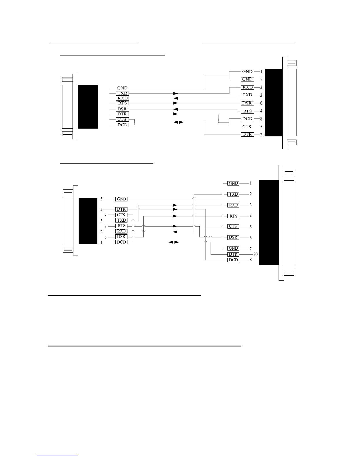
9 PIN D CONNECTOR 25 PIN D CONNECTOR
SCHEMATIC REPRESENTATION
5
3
2
7
6
4
8
1
ACTUAL REPRESENTATION
9 Pin D Serial Port To A Modem.
If you are connecting a MODEM to a 9 pin D Serial Port then
you will NOT need a cross over cable and a straight through cable
connected as the 9 to 25 pin adapter given in Figure 5-5.
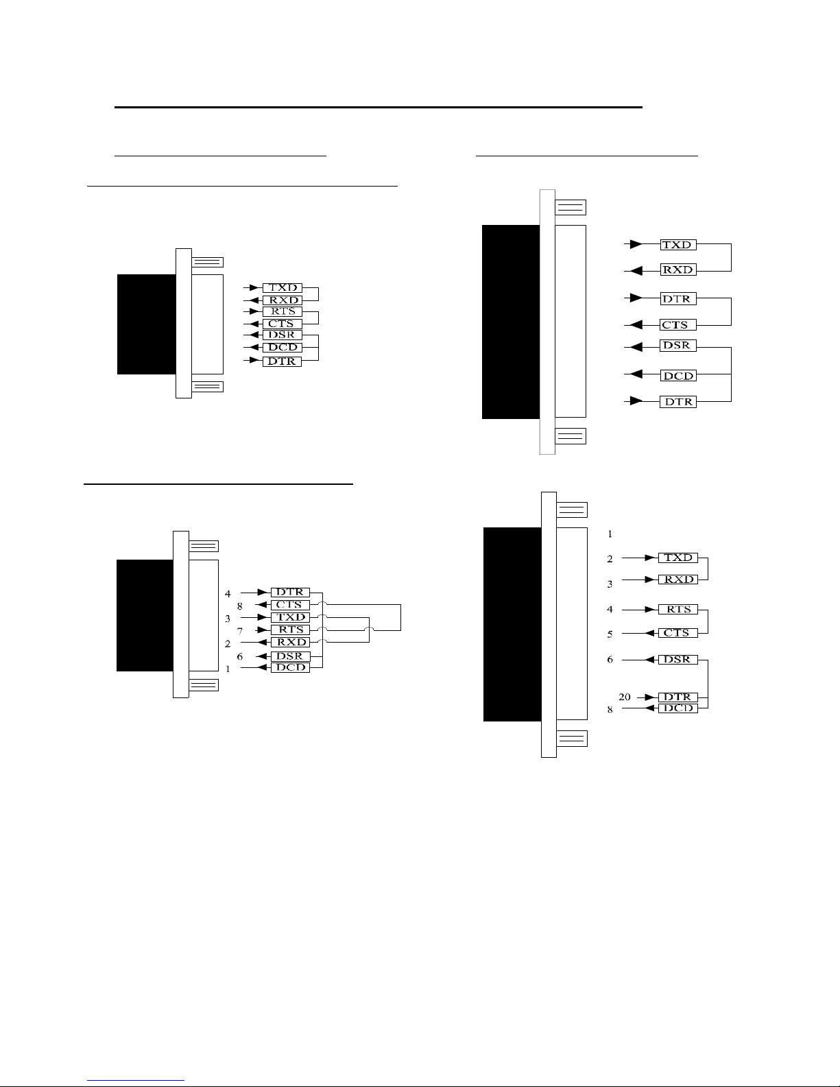
9 Pin D Serial Port Loop Back Connector.
A loop back connector can be used to echo RS232 data
transmitted by a serial port back into its own RS232 receiver. In
this way, the function of the serial port can be tested.
For an AT style Serial Port use the a female 9 way connector
wired as in Figure 5-4.
Chapter 5 Page 52
Page 51
PCI Quad RS232 RS232 Pinouts & Cabling
20
Figure 5-4. 9 Pin D Serial Loop Back Connector.
9 PIN D CONNECTOR 25 PIN D CONNECTOR
SCHEMATIC REPRESENTATION:
2
3
3
2
7
8
6
1
4
4
5
6
8
ACTUAL REPRESENTATION:
Chapter 5 Page 53
Page 52
PCI Quad RS232 RS232 Pinouts & Cabling
Figure 5-5. 9 To 25 Way Adapter.
This adapter cable makes th e AT style 9 pin serial port,
look like the standard PC 25 pin serial port. It is NOT a cross over
cable!
9 Pin AT SERIAL PORT 25 Pin PC SERIAL PORT
9 Pin Female D Connector 25 Pin Male D Connector
SCHEMATIC REPRESENTATION
GND
GND
GND
5
DCD
1
RXD
2
TXD
3
DTR
4
DSR
6
RTS
7
CTS
8
9
RI
DCD
RXD
TXD
DTR
DSR
RTS
CTS
RI
ACTUAL REPRESENTATION
5
9
4
8
3
7
2
6
1
GND
RI
DTR
CTS
TXD
RTS
RXD
DSR
DCD
GND
TXD
RXD
RTS
CTS
DSR
GND
DTR
DCD
RI
Chapter 5 Page 54
Page 53

Index
adapter................................................................................. 52, 54
address / addresses .....................................................................37
BBCARDS.EXE..................................................................14, 36
BIOS..........................................................................................37
bits..............................................................................9, 11, 38, 48
cable ....................................................... 11, 12, 38, 48, 49, 52, 54
Changing COM numbers in Windows 95................................... 27
command ...................................................................................37
Configuring ports in Windows 95 & 98...................................... 28
Configuring Ports In Windows NT 4.0.......................................34
connectors............................................................................. 12, 49
cross over........................................................................49, 52, 54
CTS ...........................................................................................50
data word length...........................................................................9
DCD ..........................................................................................50
DSR...........................................................................................50
DTR ........................................................................................... 50
handshake ..................................................................................50
installation ........................................................................... 11, 38
Installing Ports In Windows 3.x ................................................. 14
Installing Ports In Windows 95 & 98.......................................... 22
Installing Ports in Windows NT 4.0............................................31
Interrupt / Interrupts...................................................................39
jumper........................................................................................11
loop back ............................................................................. 48, 52
LPT1 / LPT2 / LPT3.................................................................. 38
Multiport Settings ......................................................................19
pin outs................................................................................ 48, 50
port / ports..............................11, 31, 37, 38, 39, 48, 49, 50, 52, 54
receive .......................................................................................50
RS232........................................................... 11, 14, 38, 48, 49, 52
RTS ...........................................................................................50
RXD ..........................................................................................50
Page 54

serial port.....................................11, 31, 37, 38, 39, 48, 50, 52, 54
serial port address.......................................................................37
setup .......................................................................................... 37
SISR ...................................................................15, 19, 20, 36, 37
stop bits................................................................................11, 38
TXD...........................................................................................50
Uninstalling Serial Solutions PCI for Windows NT....................35
utility disk.................................................................................. 37
Windows................................................................................ 4, 31
 Loading...