

Page 1

brain boxes
4.22 Edition April 2001
PARALLEL, SERIAL AND IEEE INTERFACE
P.S.I. BOX
Page 2

Guarantee.
FULL 36 MONTHS GUARANTEE.
BRAIN BOXES guarantee your PSI BOX for a full 36 months from
purchase, parts and labour, provided it has been used in the specified
manner. In the unlikely event of failure return your interface to BRAIN
BOXES or to your Dealer, with proof of purchase, who will deter-
mine whether to repair or replace this product with an equivalent
unit.
COPYRIGHT.
COPYRIGHT © 1985-2001 BRAIN BOXES.
All rights reserved. No part of this hardware, circuitry or manual may
be duplicated, copied, transmitted or reproduced in any way without
the prior written consent of BRAIN BOXES.
PSI BOX is designed, manufactured and supported by
BRAIN BOXES.
Unit 3C, Wavertree Boulevard South,
Wavertree Technology Park,
Liverpool, L7 9PF,
England.
Telephone: 0151-220 2500
Fax: 0151-252 0446
E-mail: [email protected]
Web: www.brainboxes.com
ACKNOWLEDGEMENTS.
BRAIN BOXES is a trademark of BRAIN BOXES.
IBM, Commodore, COMPAQ, Olivetti, AMSTRAD, Hewlett
Packard, H.P. and EPSON are trademarks of the relevant compa-
nies. OS/2 and Microchannel Architecture are trademarks of IBM.
Windows is a trademark of Microsoft.
Page 3

PSI BOX Reference
Thank You For Buying The
PSI BOX!
We proudly present the PSI BOX.
The PSI BOX is a very flexible 3 way converter. The PSI
BOX converts signals between IEEE488, RS232C and Centronics
Parallel. The PSI BOX can allow the signals to be passed
between any combination of the different ports. The PSI BOX is
the one stop solution to your interfacing problems.
The PSI BOX PLUS+ allows any computer with a serial
port to become an IEEE bus controller, exercising complete
control over a whole bus full of IEEE instruments. The built in
industry standard IEEE command language gives the user of any
computer, PC, PS/2, micro, mini or mainframe precise control
over the huge range of industry standard IEEE 488 devices.
The PSI BOX PLUS+ includes a disk with two sample
communications programs for use in Mode 7.
Your interface is designed and manufactured in England,
and our policy is one of complete support to our dealers and
direct to our users. The PSI BOX is designed ’in house’ and is
completely understood by our staff. Its great strength is the
support we give it. Our intention is to supply the software and
any technical information you may need to allow you to exercise
complete control over the PSI BOX allowing you to interface
many different types of equipment with each other.
After searching the manuals, do not hesitate to contact us
on our HOTLINE number given on page Intro-2, if you need
help.
We trust that if you adhere to the following instructions
you will enjoy many years of useful service from your interface.
Intro-3
Page 4

PSI BOX Reference
PSI BOX MANUAL__________________
The Layout Of This Manual._________________________
This manual is a complete description of how to install and
use the PSI BOX and PSI BOX PLUS+ interfaces.
The PSI BOX is a very flexible 3 way converter. The PSI
BOX converts signals between IEEE488, RS232C and Centronics
Parallel. The PSI BOX can allow the signals to be passed
between any combination of the different ports. The PSI BOX
allows data to be transferred between the popular communication
standards available today. The PSI BOX is thus the one stop
solution to your interfacing problems.
The PSI BOX PLUS+ is an enhanced version of the basic
PSI BOX. The PSI BOX PLUS+ includes an extra mode as
standard Mode 7. This mode allows any computer with an
RS232 port to act as the controller of a whole bus full of IEEE
instruments. Mode 7 has a powerful but easy to understand
industry standard IEEE control language built in that is designed
to make instrument control as flexible and as straight forward as
possible.
We have harnessed the power of the RS232 port, the parallel
port and the GPIB BUS allowing you to get the most out of
your IEEE devices!
The PSI BOX can be customised to suit your individual needs.
Whether it means including a new mode to interconnect your
peripherals or whether it means adding a specialised port to
connect to a non standard device we are happy to quote a cost
and delivery designed to suit you!
Chapter 1, Setting Up The PSI BOX, introduces
the PSI BOX and explains the function of the various modes and
Intro-4
Page 5

PSI BOX Reference
instructs you how to configure the PSI BOX to suit your needs.
The use of the Buffer On switch is explained.
Chapter 2, An Introduction To The IEEE-488
Interface Bus Standard
, is a general guide to this widely
used international standard. It explains how the different IEEE
devices always know who is sending information and who is
receiving information. It explains what is expected of the
controller of the IEEE bus. It explains the general concepts
involved in understanding, and using, the IEEE-488 Bus.
Chapter 3, The IEEE Port, gives details of the IEEE
connector pin outs, the function of IEEE DIP switches and
LEDs.
Chapter 4, The Centronics Parallel Port, gives
details of the parallel port connector pin outs, the function of
Centronics Output DIP switch and the Centronics LEDs, the
parallel port input and output handshake.
Chapter 5, The RS232 Serial Port, gives details of
the serial port connector pin outs, the function of RS232 DIP
switches and LEDs, how to set the baud rate, parity and RS232
handshake options. Details of how to connect the PSI BOX
serial port to both an IBM PC and a modem are included.
Chapter 6, The PSI BOX Modes 1-6 & 8,
explains the differences between these operating modes of the
PSI BOX. This includes a description of how the data transfer is
performed. Typical applications of each mode are given.
Modes 1-6 are typically used to interconnect IEEE printers
and plotters to computers with only serial or parallel ports.
Or to connect IEEE-488 computers to serial and parallel
Intro-5
Page 6

PSI BOX Reference
devices such as laser printers and modems.
Mode 8 is used at allow an IEEE plotter than uses Hewlett
Packard Graphic Language to completely emulate the RS232
equivalent plotter. HPGL plotting commands, HPGL output
commands and RS232 flow control being catered for.
Chapter 7, The PSI BOX Mode 7 Overview,
contains as a short summary of the Mode 7, details about the
Mode 7 power up messages, the Mode 7 default parameters, data
pass through mode, the BUS command sequence, sending data to
IEEE devices, receiving data from IEEE devices, IEEE control
status string, the RESET command and character, the current
device, a summary of the BUS command language and finally
the Mode 7 memory allocation.
Mode 7 is typically used as a means of controlling a
whole bus full of IEEE instruments from the RS232 serial
port of any computer.
Chapter 8, The IEEE BUS Command Language
Controls and Functions, lists and explains the full range of
IEEE controls and functions currently supported by the enhanced
PSI BOX PLUS+ Mode 7 IEEE command language. This
chapter details the command syntax, parameters and actual IEEE
bus transactions that take place. The IEEE functions are a
comprehensive set of commands that allow complete control of
the IEEE bus, right from the individual line logic levels to
performing complete parallel or serial poll routines on multiple
devices. Knowing how to access these commands is the key to
realising the full benefits of the powerful software that makes
the PSI BOX PLUS+ a magnificent asset.
The Cumulative Index covers the complete contents
of the manual.
Intro-6
Page 7

PSI BOX Reference
What Machine Do You Need?__________________________
The PSI BOX is designed to work with as wide a range of
computers IEEE devices and peripheral as possible.
Of course, we have not tried EVERY IEEE device and
EVERY computer available but we’ve yet to find one that can
not be made to work! Any comers should phone us on our
HOTLINE and we will see what we can do!
Intro-7
Page 8

PSI BOX Reference
Outline Contents.________________
Chapter 1. Setting Up The PSI BOX.
Chapter 2. An Introduction to the IEEE 488
Interface Bus Standard.
Chapter 3. The IEEE Port.
Chapter 4. The Centronics Parallel Port.
Chapter 5. The RS232 Serial Port.
Chapter 6. The PSI BOX Modes 1-6 & 8 With
Typical Application Examples.
Chapter 7. The PSI BOX Mode 7 Overview
Chapter 8. The IEEE BUS Command Language
Controls and Functions.
Cumulative Index.
Intro-8
Page 9

PSI BOX Reference
Contents________
Chapter 1 Setting Up The PSI BOX.
Introduction. 1
The PSI BOX. 1
The PSI BOX Modes. 3
The Buffer Switch. 4
Setting It All Up. 6
Configuring The PSI BOX. 6
Problems! 8
Chapter 1 List Of Figures.
Figure 1-1. The Buffer Switch. 4
Figure 1-2. Buffer Option. 5
Figure 1-3. The Buffer Allocation. 5
Figure 1-4 The Power LED. 6
Chapter 2 An Introduction to IEEE 488 Bus Standard.
Introduction. 9
The IEEE 488 Standard. 9
The Beginnings Of A New Standard. 9
What Exactly Is IEEE 488? 10
What’s In A Name? 10
IEEE 488-1975. 11
The IEEE Signal Lines. 12
The IEEE Signal Lines. 12
The Data Bus Signals. 12
The Handshake Signals. 12
DAV Data Valid. 13
NRFD Not Ready For Data. 13
NDAC Not Data Accepted. 13
The Management Signals. 13
ATN Attention. 14
IFC Interface Clear. 14
REN Remote Enable. 14
SRQ Service Request. 14
EOI End Or Identify. 15
Negative Logic 15
Intro-9
Page 10

PSI BOX Reference
Cabling Lengths and Data Transfer Speeds. 15
Using The IEEE Bus. 16
Types Of IEEE Devices. 16
The Listener. 16
The Talker. 16
The Controller. 17
The Controller In Charge. 17
The System Controller. 17
Controller Summary. 18
Command Mode And Data Mode. 18
Addresses. 19
Talk Only And Listen Only Devices. 20
Serial Poll. 20
Parallel Poll. 21
Device Clear and Device Trigger. 22
Remote - Local Functions. 23
End Of Sequence Termination, 23
Chapter 3 The IEEE Port.
Introduction. 25
The IEEE Leds. 26
The IEEE DIP Switches. 27
Setting The IEEE Address. 28
Setting The Controller State. 28
IEEE Cables. 29
Chapter 3 List Of Figures.
Figure 3-1. The IEEE Leds. 27
Figure 3-2. The IEEE DIP Switches. 27
Figure 3-3. Setting The IEEE Address. 28
Figure 3-4. The Controller State. 29
Figure 3-5. The IEEE Port Pin Outs. 30
Chapter 4 The Centronics Parallel Port.
Introduction. 31
Centronics Leds. 32
Selecting The Direction Of The Centronics Port. 32
Intro-10
Page 11

PSI BOX Reference
The Centronics Output Handshake. 33
The Centronics Input Handshake. 34
Centronics Cables. 35
Chapter 4 List Of Figures.
Figure 4-1. The Centronics Leds. 32
Figure 4-2. Setting Parallel Port Direction. 33
Figure 4-3 The Centronics Output Port Pin Outs. 35
Figure 4-4. The Centronics Input Port Pin Outs. 36
Figure 4-5. Centronics Input From PC Printer Port. 36
Chapter 5 The RS232 Serial Port.
Introduction. 37
RS232 Leds. 38
The RS232 DIP Switches. 39
Setting The Baud Rate. 39
The RS232 Handshake. 39
The Hard Wired Handshake. 40
The XON/ XOFF Handshake. 41
Setting The Parity Options. 43
Setting The Data Word Length. 43
RS232 Port Cables. 44
Connecting To An IBM PC Serial Port. 44
Connecting To A Modem. 45
Loop Back Connector. 46
Chapter 5 List Of Figures.
Figure 5-1. The RS232 Leds. 38
Figure 5-2. The RS232 DIP Switches. 38
Figure 5-3. Baud Rate Settings. 39
Figure 5-4. Selecting The RS232 Handshake. 40
Figure 5-5. Parity Option. 42
Figure 5-6. The Data Word Length. 43
Figure 5-7. The RS232 Port Pin Outs. 45
Figure 5-8. The Loop Back Connector. 46
Figure 5-10. PSI Box To PC Serial Port Cable. 46
Figure 5-9. Connecting To The RS232 Port. 47
Figure 5-11. PSI Box To AT Serial Port Cable. 47
Intro-11
Page 12

PSI BOX Reference
Figure 5-12. IBM AT To PC Serial Port Cable. 48
Chapter 6 Modes 1-6 & 8 With Application Examples.
Introduction. 49
The Mode Switches. 49
Mode 1. 51
Mode 2. 54
The Mode 1+2 IEEE Handshake. 56
The Mode 1+2 Secondary Addresses. 56
Mode 3. 58
Mode 4. 59
Mode 5. 60
Mode 6. 62
Mode 8. 64
Chapter 6 List Of Figures.
Figure 6-1 The Mode DIP Switches Settings. 50
Figure 6-2 HPGL Output Commands. 65
Figure 6-3 HPGL RS232 I/f Flow Control Commands. 66
Chapter 7 The PSI BOX Mode 7 Overview
Introduction. 68
Mode 7 In 15 Minutes!. 68
Mode 7 Summary. 69
Mode 7 Power Up. 70
The Default Mode 7 Configuration. 71
Data Pass Through Mode. 72
The BUS Command Sequence. 73
Sending Data Using The Bus Command. 75
Receiving Data Using The Bus Command. 75
The IEEE Control Status String. 76
The RESET Command and Character. 79
The Current Device. 79
Mode 7 BUS Command Summary. 81
Mode 7 Memory Allocation. 82
Chapter 7 List Of Figures.
Intro-12
Page 13

PSI BOX Reference
Figure 7-1 The Default Mode 7 Configuration. 72
Figure 7-2 The IEEE Control Status String. 78
Figure 7-3 Mode 7 IEEE Command Primitives 81
Figure 7-4 Mode 7 IEEE Line Controls. 81
Figure 7-5 Mode 7 IEEE Command Functions. 82
Chapter 8 The IEEE BUS Command Language
Introduction. 84
Valid Parameters. 84
ABORT. Terminate Activity, Reset Devices. 87
ATN. Assert The Atn Line. 88
CLEAR. Resets All or Specified Devices. 89
CMD. Send A Byte With Attention True. 90
CONFIGURE.
Specifies Devices Parall Poll Response. 92
DATA. Send A Byte With Attention False. 94
DCL. Sends The Device Clear Command. 95
DISABLE. Prevents Devices Responding Parallel Poll. 96
END=. Set The End Of Output Method. 97
END=OFF. Disable EOI During A Bus Write. 99
END=ON. Set The End Of Output Method. 100
EOI. Send A Data Byte With Eoi True. 101
EOS=. Set End Of Sequence Character For Inputs. 102
GET. Sends Group Execute Trigger. 104
GTL. Sends The Go To Local Command. 105
IFC. Pulse The IFC Line. 106
LAG. Sends The Listen Address. 107
LISTEN. Sends The Listen Address. 108
LLO. Sends The Local Lockout Command. 109
LOCAL. Set Some Or All Devices To Local Control. 110
LOCKOUT. Sends The Local Lockout Command. 111
MACRO. Defines Or Lists Macro. 112
MESSAGES=OFF.
Disable PSI BOX Messages. 114
MESSAGES=ON.
Enable PSI BOX Messages. 115
MLA. Sends My Listen Address. 116
MLA=. Sets Or Changes PSI BOX Listen Address. 117
Intro-13
Page 14

PSI BOX Reference
MSA. Sends My Secondary Address. 118
MSA=. Set/ Change PSIBOX Secondary Address. 119
MTA. Sends My Talk Address. 120
MLA=. Sets Or Changes PSI BOX Listen Address. 121
NO ATN. Release The Atn Line. 122
NO REN. Release The Ren Line. 123
NO TO. Disable The Timeouts. 124
OUTPUT. Send A String Of Data To A Bus Device. 126
PPC. Sends Parallel Poll Configure. 127
PPD. Sends Parallel Poll Disable. 129
PPE. Sends Parallel Poll Enable Command. 131
PPOLL. Perform A Parallel Poll. 133
PPU. Sends Parallel Poll Unconfigure. 135
READ. Receive One Byte From Addressed Talker. 136
REMOTE. Put Device Under PSI BOX Control. 137
REN. Assert The Ren Line. 138
RESET. Specifies The Power On Reset Character. 139
SEC. Sends The Secondary Address. 140
SDC. Sends Selective Device Clear Command. 141
SHOW. Display & Explain Control Status String. 142
SPD. Sends Serial Poll Disable Command. 143
SPE. Sends Serial Poll Enable Command. 144
SPOLL. Perform A Complete Serial Poll. 146
STATUS. Send The Status String To RS232 Host. 148
STRING. Send A String Of Data To A Bus Device. 150
TAD. Sends The Talk Address. 151
TALK. Sends The Talk Address. 152
TCT. Sends The Take Control Command. 153
TIMER. Wait For X Milli Seconds. 154
TO. Set The Timeout Period. 155
TRIGGER. Tell Devices Perform Predefined Action. 157
Unconfigure. Prevents Devices Responding To PPoll. 158
UNL. Sends The Unlisten Command. 159
UNT. Sends The Untalk Command. 160
VERSION. Send PSI Rom Version To RS232 Host. 161
WAIT. Wait For X Milli Seconds. 162
WAIT SRQ. Wait Till Srq Is True. 163
X. Executes Stored Macro. 164
Intro-14
Page 15

Setting Up The PSI BOX. PSI BOX Reference
Chapter 1 Page 1
CHAPTER 1
SETTING UP
THE
PSI BOX
Introduction.
This chapter introduces the PSI BOX, outlines the function of the
various modes and instructs you how power up and to configure the
PSI BOX to suit your needs.
Finally, the allocation of the buffer and the function of the
Buffer On DIP switch is explained.
The PSI BOX.
A 6 Volt adapter supplies power to the PSI box. The front of the PSI
BOX consists of 7 LEDs and two sets of 8 DIP switches. The 16 DIP
switches allow the user to select options whilst the LEDs are used to
monitor progress of data transfers. The set of DIP switches nearest the
LEDs is switch block one. The switches dedicated to the RS232 port
options is switch block two.
Mounted on the back of the PSI BOX are a standard IEEE488
plug, a 25 way male RS232 D connector, a 25 way female Centronics
Parallel D connector. Each port has two LEDs dedicated to it and a
further LED is the mains power indicator. The mains connector is a
fused, switched power inlet.
Inside the PSI BOX is an R.F.I. shielded, mains transformer and a
printed circuit board containing an enhanced microprocessor, a ram
buffer, interface logic and appropriate line drivers for the 3 ports.
Page 16

PSI BOX Reference Setting Up The PSI BOX
The IEEE plug is an industry standard gold plated and
EMI shielded connector. The IEEE base address is front panel
DIP switchable in the range 0-15. In addition, certain modes use
address 15 to select listen only or talk only operation.
The Centronics Parallel port is an IBM PC printer
compatible port. The Centronics Parallel port is an IBM PC
compatible printer port and may be either an input or an output.
The connector is identical to PC parallel port LPT1.
The RS232 port signals are the industry standard +/- 12
Volt level. The serial port is an IBM PC serial compatible port.
The connector has the same pin outs as the IBM PC serial port
COM1:
The serial port is bi-directional. The RS232 handshake can
be either a hardware handshake controlled by the DSR, CTS,
DCD and DTR, RTS pins or by the XON/ XOFF software
handshake. The baud rate and parity options are selectable from
either the front panel or under software control from the IEEE
port.
Baud rates of between 75 to 19200 baud are available.
Parity may be off or on, even or odd. The may be either 7 or 8
data bits per word.
The internal buffer is 32K ram and may be disabled by
front panel DIP switch control. A valuable aide in debugging
your communication problems!
The main power inlet is a fused switchable unit.
Fuse rating 3 Amp. The fused connector contains a spare 3 Amp
fuse, just in case you might need it. The PSI BOX even comes
complete with a fused 13 Amp plug.!
The PSI BOX is a slim, brick shaped and is 10.3 inches
long x 2.4 high x 5.5 wide. (262 long x 61 high x 140 wide
millimetres.) The PSI BOX weighs 5 lb, that is 2 kg.
Page 2 Chapter 1
Page 17

Setting Up The PSI BOX. PSI BOX Reference
The PSI BOX Modes.___________________
The PSI BOX is controlled by its ROM based operating
system. It is a stand alone converter unit. It has the ability to
work with many different computers and can easily overcome
the difficulties in allowing these computers to communicate with
each other.
The PSI BOX is flexible enough to allow operation in
many different modes, and so solve many different types of
problems. These modes are selected by the user when he sets the
front panel DIP switches. The PSI BOX may be either an IEEE
device or the IEEE controller. Alternatively the PSI BOX can be
used to convert between RS232 and Centronics parallel.
The following modes of operation are currently available.
In modes 1 and 2 the PSI BOX is an IEEE 488 device attached
to an IEEE controller computer.
MODE 1 IEEE 488 to RS232, bi-directional.________
IEEE 488 from Centronics Parallel input.
MODE 2 IEEE 488 to RS232, bi-directional.________
IEEE 488 to Centronics Parallel output.
The IEEE port is not in use in modes 3 and 4.
MODE 3 Centronics Parallel input to RS232 output.________
MODE 4 RS232 input to Centronics Parallel output.________
In modes 5, 6 & 8 the PSI BOX is the IEEE 488 controller.
Data input is not from an IEEE computer. Only one IEEE
device may be accessed and that only as an output device, ie an
IEEE printer or plotter.
MODE 5 Centronics Parallel input to IEEE 488 output.________
Chapter 1 Page 3
Page 18
PSI BOX Reference Setting Up The PSI BOX
MODE 6 RS232 input to IEEE 488 output.________
MODE 8 RS232 input to IEEE 488 output with talk back.________
Allows HP IEEE plotters to fully emulate Rs232
version.
In mode 7, only available on the PSI BOX PLUS+, the PSI
BOX is the IEEE 488 controller. The RS232 port of the host
computer is used to control the IEEE bus. An enhanced
control language is used to address many IEEE devices and
to provide complete instrumentation control.
MODE 7 RS232 bi-directional to IEEE 488, full control of________
IEEE bus of up to 14 instruments or devices.
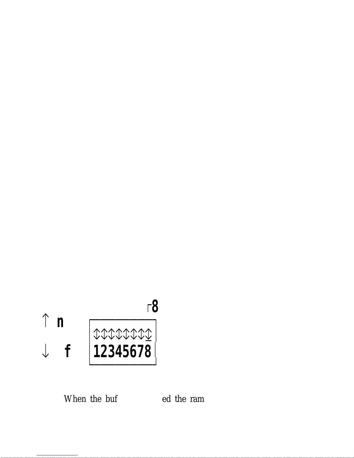
The Buffer Switch._________________
The 32K ram buffer can be either in operation or
bypassed. DIP switch 8 on switch block 2 selects whether the
internal ram buffer will be in use.
Figure 1-1. The Buffer Switch.__________________________
Ú
8
Buffer On
å
on
ЪДДДДДДДД¿
³гггггггд³
æ
off
³
12345678
³
АДДДДДДДДЩ
When the buffer is enabled the ram is divided up between
the various ports in use.
Page 4 Chapter 1
Page 19

Setting Up The PSI BOX. PSI BOX Reference
In general, the buffer is divided as follows. Half of the
available ram is used for the Centronics port and half is used for
the RS232 port. The RS232 port partitions its share of the ram
buffer evenly between input and output. With the Centronics and
RS232 ports both being buffered there is no need for the IEEE
port to be buffered.
Due to the many different modes of operation of the PSI
BOX the ram buffer partition may be different from that
described above. The PSI BOX alters the general case to suit the
mode actually in use.
When the buffer is disabled then each of the active ports
has a 2 byte buffer. This two byte buffer gives a better flow of
data than actually having no buffer at all!.
Figure 1-2. Buffer Option._______________________
DIP 8 BUFFER OPTION CHOSEN._____ _____________________
0=Off NO BUFFER IN USE.
1=On BUFFER ENABLED
Figure 1-3. The Buffer Allocation._____________________________
Mode RS232 RS232 CENTRONICS CENTRONICS____ _____ _____ __________ __________
INPUT OUTPUT INPUT OUTPUT_____ ______ _____ ______
1 8192 8192 14848 0
2 8192 8192 0 14848
3 0 16128 14848 0
4 16128 0 0 14848
5 0 0 30720 0
6 30720 0 0 0
7 15360 15360 0 0
8 28672 2048 0 0
It is anticipated that enhancements to the basic PSI BOX
will be available as time progresses. These enhancements will
probably include memory upgrades, improvements to the ROM
based software and further input - output options.
Chapter 1 Page 5
Page 20
PSI BOX Reference Setting Up The PSI BOX
Setting It All Up._______________
The PSI BOX comes complete with a mains cable and a
fused 13 Amp plug.
Connect the mains cable to the inlet on the back of the PSI
BOX. Plug the 13 Amp plug end into a suitable mains outlet.
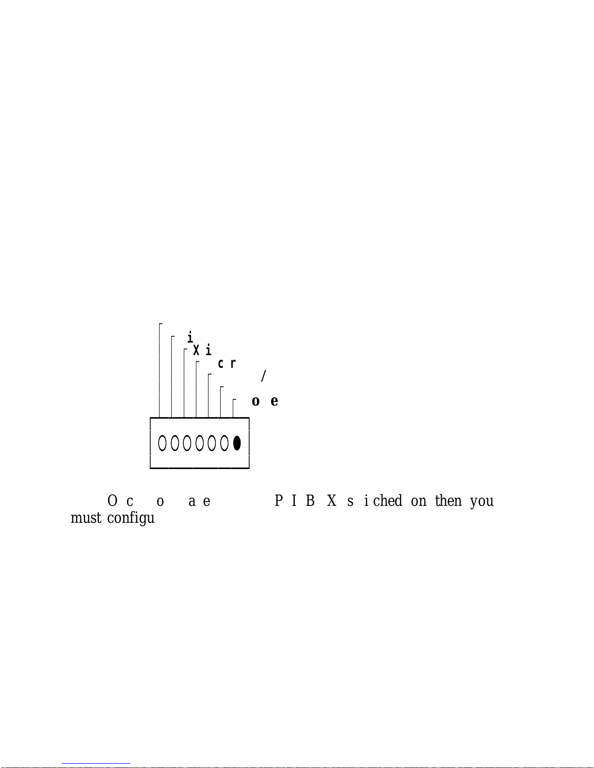
Using the switch on the back of the PSI BOX switch the
PSI BOX on. LED 7 on the front of the PSI BOX is the power
LED. It lights up RED when the PSI is switched on. If the PSI
BOX does not power up check the cable connections and the
mains switches. If you still have trouble please contact your
dealer.
Figure 1-4 The Power LED. _________________________
Ú
Talk
³ Ú
Listen
³ ³ Ú
Xmit
³ ³ ³ Ú
Recvr
³ ³ ³ ³ Ú
Centr O/P
³ ³ ³ ³ ³ Ú
Centr I/P
³ ³ ³ ³ ³ ³ Ú
Power On
³ ³ ³ ³ ³ ³ ³
ЪДДДДДДД¿
³○○○○○○â³
АДДДДДДДЩ
Once you have got the PSI BOX switched on then you
must configure each port ready for use. Consult the sections that
follow, for specific details on each port, and the MODE
SETTING instructions. The details given should be sufficient to
resolve any ambiguities.
Configuring The PSI BOX.________________________
Don’t be confused by the flexibility of the PSI BOX, it is
really quite easy to make it perform the way you want.
To configure the PSI BOX follow these steps:-
Page 6 Chapter 1
Page 21

Setting Up The PSI BOX. PSI BOX Reference
1) Determine whether you are going to use your Centronics
Parallel Port as an input or output. If this port is not in use
then set it as an output.
2) Set up the RS232 port options, baud rate, parity etc.
3) Determine whether you want the PSI BOX to be an IEEE
device or the IEEE controller.
If it is an IEEE device then it will be controlled by
commands from, say, a Commodore PET or Hewlett
Packard computer.
If the PSI BOX is the IEEE controller then you are using
it to control an IEEE instrument or other device from the
serial or parallel port of some computer.
4) If the PSI is an IEEE device then select the IEEE base
address. This gives the address of the RS232 port, the
address of the Centronics Parallel port is one more than the
base address set by the dip switches.
5) If the IEEE port is acting as the controller to an IEEE
instrument then set the mode switches to correctly
determine exactly how the IEEE device gets its instructions
and which of the RS232 or Centronics port is generating
the IEEE data.
6) Connect up all your cables and away you go.
7) If you are having a problem watch the way the LEDs blink
this can give you valuable information about where the
fault lies.
8) If the RS232 port appears to be at fault, then use a loop
back connector on the RS232 port. This will allow you to
determine whether the fault is due to the RS232 cross over
cable used, incorrect baud rates or wrong mode switch
settings.
Chapter 1 Page 7
Page 22

PSI BOX Reference Setting Up The PSI BOX
Problems!_________
You won’t have any problems! BUT if you do it probably
due to the RS232 port cross over cable being wired incorrectly.
First make sure that you have read the followed the steps above,
next re read the relevant sections of this manual. For further
advice, please contact your dealer.
Page 8 Chapter 1
Page 23

IEEE 488 Introduction PSI BOX Reference
CHAPTER 2
AN INTRODUCTION TO
THE IEEE-488
INTERFACE BUS
STANDARD.
Introduction.____________
This chapter is divided in to the following main parts.
"The IEEE 488 Standard" takes a look at how the IEEE 488
standard came into being, and gives a simple definition of what
the bus actually is.
"The IEEE Signal Lines" is a brief look at the bus signal lines,
talks about cable length restrictions and data transfer speed
limits.
In "Using The IEEE Bus" the major features of the IEEE 488
system are described.
If you know little about IEEE we suggest that you browse
though the first two parts of this chapter and then carefully read
the rest.
The IEEE 488 Standard.______________________
The Beginnings Of A New Standard.________________________________
In September 1965 the Hewlett Packard Company realised
that it needed to standardise the way in which all future H.P.
instruments would communicate with each other. The HPIB is
defined.
In March 1972, the IEC committee accepts HPIB as a
starting point for the draft document of its IEC standard which is
published in June 1980 as IEC 625-1.
In April 1975, the Institute of Electrical and Electronics
Chapter 2 Page 9
Page 24

PSI BOX Reference IEEE 488 Introduction
Engineers published IEEE 488, this is revised in November 1978
and again in 1980.
By 1986 more than 250 manufacturers in more than 14
countries throughout the world are building over 2000 different
IEEE 488 based products..... and the PSI BOX lets you control
them all from your desk top PC!
What Exactly Is IEEE 488?________________________
Basically IEEE 488 is a way of connecting electronic
instruments together and putting them under computer control.
The IEEE 488 standard describes a connecting plug, a set
of 16 signal wires and 8 earth wires and sets out the way that
each instrument may send and receive data.
By strictly defining these parameters in an unambiguous
way, the IEEE 488 standard has become powerful though its
ease of use and straight forward implementation.
Any one who has ever attempted to link two RS232C
devices together will admire the no soldering, piggy back style,
cable connection and the no baud rate, parity free, high speed
IEEE 488 data exchange.
The intelligence of the IEEE 488 system is built into the
interface and does not lie in the user’s ability to decipher how to
wire up a cross-over or null modem cable!
What’s In A Name?__________________
There are four international standards governing byte serial
bit parallel interface systems for instruments.
IEEE-488 The IEEE-488 standard is also known as the
___________
General Purpose Interface Bus, GPIB, the
Hewlett Packard Interface Bus, HPIB, IEEE
Bus, PLUS Bus and even the ASCII Bus.
ANSI MC1.1 This is identical to the IEEE standard.
_______________
Page 10 Chapter 2
Page 25

IEEE 488 Introduction PSI BOX Reference
IEC 625 This European standard is identical to the IEEE
_________
standard except for the connector. It uses a 25
pin D type RS232C style connector.
BS6146 This British standard is identical to IEC 625
_________
NOTE: Never, ever connect an IEC 625 system to an
RS232C system. The =/- 12 Volts of the RS232C system can
seriously damage the 5 Volt TTL IEC 625 system!
IEEE 488-1975.______________
The full name of the IEEE Standard 488-1975 is "A
Digital Interface for Programmable Instrumentation". It defines a
byte serial bit parallel interface for instrument systems. What
does this mean?
By Digital Interface it means that the signal on any of the
16 signal lines is either high or low. The voltage on each line
represents the On or Off state. So the data exchanged between
the devices connected together is digital.
Bit Parallel means that 8 lines are used to simultaneously
transmit a whole byte of data. These 8 lines are called
collectively the Data Bus. The data on the bus ranges in value
from 0 to 255. Since data is sent 8 bits at a time the IEEE bus
is inherently faster than the one bit at time RS232 system.
Byte Serial means that consecutive bytes of data are sent
one after another. Another example of bit parallel byte serial
data transfer is the Centronics Parallel printer connection found
on most PC’s.
Programmable Instrumentation means that the devices
attached to the IEEE bus are usually capable of being instructed
to perform several different tasks in a sequence. Often an IEEE
system comprises devices that can measure various parameters
and devices that can generate various stumulii. For example a
programmable IEEE voltage generator may be instructed to apply
several voltages across a resistor, whilst a programmable IEEE
Ammeter may be used to measure the current through the
Chapter 2 Page 11
Page 26

PSI BOX Reference IEEE 488 Introduction
resistor once the voltage has stabilised. In this way IEEE
instruments can be easily built up to form a simple but effective
automatic test system.
So the IEEE Standard 488 specifies a digital interface for
programmable instrumentation, that is, it is a way of interconnecting electronic measuring and control apparatus.
The IEEE Signal Lines._____________________
The IEEE Signal Lines._____________________
The IEEE 488 defines the use of a parallel bus to
interconnect up to 15 instruments. Each device on the bus is
connected to the 16 signal lines and 8 ground lines on the bus.
These 16 signal lines can be considered as three separate groups.
Eight of the lines are used to carry data and commands. Three
lines control the transfer of the data. Whilst the remaining five
lines are for general interface management.
These three groups are the 8 Data Bus signals, the 3 Handshake
signals and the 5 Management signals.
The Data Bus Signals.___________________
The 8 data bus signals are called DIO1 to DIO8.
The data bus carries all data, programming instructions and IEEE
interface messages. Most instruments communicate using the 7
bit ASCII code, however the information on the data bus may
represent ASCII, Binary, Hex, Octal, or whatever, characters.
The Handshake Signals._____________________
The 3 handshake signals are DAV, NRFD and NDAC.
The handshake signals control the actual transfer of each data
byte down the data bus. They provide the famous ’3-wire
handshake’ that ensures that the data is transmitted correctly and
without loss, no matter what the difference in operating speeds
Page 12 Chapter 2
Page 27

IEEE 488 Introduction PSI BOX Reference
of the participating devices.
DAV Data Valid._______________
The DAV line indicates that the data on the data lines is
good data. The DAV is controlled by the device that is putting
the data on the data bus. The DAV line is monitored by all the
devices that are accepting data from the data bus. The DAV line
is false when the data on the data bus is invalid and is true
when the data bus contains valid data.
NRFD Not Ready For Data.________________________
The NRFD line indicates the condition of readiness of
devices to accept data. The NRFD line is monitored by the
device that puts the data on the data bus. It is driven by all the
devices that are accepting data from the data bus.
The NRFD line is false when the all these devices are ready for
data and true when one or more of them is not ready for data.
NDAC Not Data Accepted._______________________
The NDAC line indicates acceptance of data by the
devices.
The NDAC line is monitored by the device that puts the data on
the data bus. It is driven by all the devices that are accepting
data from the data bus. When NDAC is true, one or more of
the listening devices have not accepted the data.
The Management Signals._______________________
The 5 management signals are ATN, IFC, SRQ REN and
EOI. These five signals are used to manage an orderly flow of
information across the bus.
The ATN and IFC lines are used by all IEEE bus devices. The
remaining three, REN, SRQ and EOI, may or may not be used
Chapter 2 Page 13
Page 28

PSI BOX Reference IEEE 488 Introduction
by a particular device.
ATN Attention.______________
All devices on the IEEE bus must monitor the ATN line.
The attention line is used by the controller to specify how data
on the data bus is to be interpreted and which devices must
respond to the data. The ATN line is set true by the controller
when it sends interface messages, such as device talk and listen
address, secondary addresses, and polling configuration messages.
The ATN is set false by the controller so that the active talker
can send device dependent messages, such as data and
programming information, to the active listeners.
IFC Interface Clear.__________________
The IFC line, interface clear, is used by the controller to
place the bus interface in a known inactive state. Only the
System Controller can set the IFC line, all other instruments
must monitor and respond to IFC. The System Controller may
set IFC true at any time.
REN Remote Enable.___________________
The REN line, remote enable, sends the remote message.
REN must be true for an device to operate under remote control
from a system controller, otherwise the device is programmed
locally from its front panel. Only the System Controller can set
the REN line, all other instruments must monitor and respond to
REN by returning to local control whenever it becomes false.
The System Controller may set REN true at any time.
SRQ Service Request.___________________
The SRQ line, service request, is used by a device to
indicate the need for attention and to request an interruption of
the current sequence of events. The controller can clear the SRQ
Page 14 Chapter 2
Page 29

IEEE 488 Introduction PSI BOX Reference
line only by performing a serial poll of the device requesting
service.
EOI End Or Identify.___________________
The EOI line, end or identify, is used by a talker to
indicate the end of a data string or, by the controller, in
conjunction with ATN, to conduct a Parallel Poll sequence.
When ATN is false, the current talker may send the END
message, indicating the end of its data, by setting EOI true at
the same time it places the last data byte on the data bus. The
controller may send the identify message, IDY, to initiate a
Parallel Poll of all devices with the Parallel Poll capability by
setting ATN and EOI true.
Negative Logic_____________
One of the things that commonly confuses IEEE bus users
is that the IEEE signals are described as using ’negative logic’.
This simply means that a signal is true when it is low, at 0.4
Volts or less, and that a signal is false when it is high, at 2.4
Volts or greater. Do not let this worry you, just think of the
different signals being either True or False.
Cabling Lengths and Data Transfer Speeds.______________________________________
You are permitted to connect up to 15 devices together on
the IEEE bus, that is one PSI BOX plus 14 other devices. This
should be more than adequate for the vast majority of users.
When more than 15 devices MUST be placed on one bus, the
GPIB can be extended with bus extenders.
The general limit for total cable length on the bus is 2
metres for every IEEE device connected. This is provided the
total transmission path length does not exceed 20 metres. There
should be not more than 4 metres of cable between any two
Chapter 2 Page 15
Page 30

PSI BOX Reference IEEE 488 Introduction
devices. Within this limit, the IEEE bus is capable of a
maximum data transfer rate of 250K bytes per second with open
collector drivers, or 500K bytes per second with tri-state drivers.
When shorter distances are involved, 15 metres, with every
device turned on, with not more than 1 device per metre of
cable and with tri-state drivers the maximum theoretical data rate
is 1 Megabyte per second.
Of course, the data is actually transmitted at the speed of
the SLOWEST currently addressed listener or talker. The
positive 3 wire handshake ensures that data is transmitted
correctly and without loss despite the actual speed in use.
Using The IEEE Bus.___________________
Types Of IEEE Devices._____________________
Every device on the IEEE bus must be capable of
acting in at least one of following three roles.
1) A device acting as a LISTENER.
2) A device acting as a TALKER.
3) A device acting as a CONTROLLER.
The Listener.____________
A listener is a device with the capability to receive data
from the IEEE bus when addressed. This transmitted data is
known as device dependant messages.
A typical listener is a printer. Other listeners include disk
drives, programmable oscilloscopes, programmable signal
generators, programmable power supplies etc. There can be up to
14 active listeners simultaneously on the IEEE bus.
The Talker.___________
A talker is a device with the capability to transmit data
over the IEEE bus when addressed. This transmitted data is
known as device dependant messages.
Page 16 Chapter 2
Page 31

IEEE 488 Introduction PSI BOX Reference
A typical example of a talker is a disk drive sending data,
a digital voltmeter sending data, a programmable oscilloscope
sending data, etc. There can be only one active talker on the
IEEE bus at any one time. When a device is commanded to talk
all other talkers are automatically commanded to untalk.
The Controller.______________
A controller is a device that can instruct other devices to
talk or to listen. In addition, the controller can send interface
messages to command specified actions within other devices. A
typical example of a controller is your PC with the PSI BOX
connected, the PSI BOX can also act as a listener or a talker
when necessary.
The Controller In Charge._______________________
If there are several controllers present on the IEEE bus
only one of them at a time can be the Controller In Charge.
When a controller is not the Controller In Charge it must be in
the controller idle state. The Controller In Charge can be in the
controller standby state or by asserting ATN true, it is the Active
Controller. So the Controller In Charge at will can move
between the Active Controller and the controller standby states.
If several controller are connected to one bus then only
one of these can be the System Controller.
The System Controller.____________________
Whilst any idle controller can be instructed to become the
Active Controller only the System Controller can MAKE
ITSELF the Active Controller at any time. Only the System
Controller can assert the IFC and REN lines.
The PSI BOX can also act as controller in standby state, as
Controller in Charge or as System Controller.
The PSI BOX, in Mode 7, powers up as System
Chapter 2 Page 17
Page 32

PSI BOX Reference IEEE 488 Introduction
Controller, this suits 99.99% of all users.
Controller Summary.___________________
To sum up the Controller states.
1) A controller commands other devices whether they should
talk, listen or perform some other action.
2) To avoid confusion, if several controller are connected to
an IEEE system, only one of them at a time is allowed to
send commands to the bus. This is the Controller In
Charge.
3) Interface messages exist for controllers to pass control
between each other, ie make each other the Controller In
Charge.
4) Only one controller on an IEEE system can be the System
Controller. The System Controller has several unique
abilities. The System Controller alone can set the IFC and
REN signals true or false. The System Controller can make
itself the Controller In Charge, at any time, by sending the
IFC signal true for 100 micro seconds.
Command Mode And Data Mode.______________________________
Two type of messages may be transmitted on the IEEE
bus. These are device dependant messages and interface
messages. Device dependant messages are distinguished from
interface messages by the state of the ATN line.
The controller asserts ATN true when it wants to send an
interface message, the IEEE bus is said to be in COMMAND
MODE. When ATN is false the data on the data bus is a device
dependant message, the IEEE bus is said to be in DATA
MODE.
Only the Active Controller can send interface messages,
that is, commands.
Any active talker can send device dependant messages, that
is, data.
Page 18 Chapter 2
Page 33

IEEE 488 Introduction PSI BOX Reference
Device dependant messages are only sent from the active
talker to the active listeners, they are ignored by all other
devices. A typical example of a device dependant message is the
data byte 13, HEX 0dH, when ATN line is false. This would be
interpreted by an actively listening IEEE printer as the
instruction to perform a carriage return. All the data that is sent
between IEEE devices are device dependant messages,
Interface messages are sent from the Controller In Charge
to the bus devices. Each device on the bus may accept and
process any or all depending on the capability of the device and
the type of command sent. The four groups of commands sent
by the controller are:-
1) Universal commands accepted by ALL devices.
2) Addressed commands accepted by all devices addressed to
listen.
3) Addresses accepted by ALL devices.
4) Secondary addresses or commands accepted by all devices
enabled by a primary address or command.
A typical example of an interface message would the data
byte 63, with ATN true, this is the interface message UNL, an
UNaddress, and it tells all devices to stop listening to any device
dependant data transfer.
Addresses.__________
Every IEEE device has at least one address. Each device
has a unique address, often set by DIP switches. The device
addresses are used by the active controller in command mode to
specify who shall talk and shall listen. Every device must be
able to recognise its own address and respond correctly to it. No
two IEEE devices, especially talkers, should be set to the same
address.
Valid addresses are in the range 0 to 30 inclusive. It is
usual that the Talk address of a device is the same as its Listen
address.
Chapter 2 Page 19
Page 34

PSI BOX Reference IEEE 488 Introduction
Talk Only And Listen Only Devices._______________________________
The only exception to addressed devices are Talk Only or
Listen Only devices. There may be only one Talk Only device
on an interface bus. When the controller is in the idle state,
ATN low, the Talk Only device will always be ready to send its
data. A Listen Only device will receive any data from any talker
no matter what other devices have also been commanded to
listen.
One of the simplest IEEE systems is with a Talk Only
digital meter and a Listen Only printer. The printer will log
every reading that the meter sends. This type of system does not
require the presence of an IEEE Controller.
In addition to the basic function of instructing devices to
talk or listen the IEEE Standard provides interface messages that
allow the controller to accomplish the following four functions.
1) Serial Polls.
2) Parallel Polls.
3) Device Clear and Device Trigger.
4) Remote/ Local functions.
Serial Poll.__________
When a device requires the attention of the controller it
asserts SRQ true. The Serial Poll is the reply that the Controller
gives to a device asserting SRQ, service request. It is the IEEE
device that causes the serial poll to be performed because it
asserts SRQ when it needs servicing by the controller.
The SERIAL POLL is used to determine which device has
requested service from the controller and why. Serial poll is the
only method that can correctly cause the device to return the
SRQ line false. In general, you will know which device
requested the service and so will know which to poll. However,
if it could be one of several devices that is requesting service,
you should perform successive serial polls on the different
devices until the SRQ line returns to the false state.
Page 20 Chapter 2
Page 35

IEEE 488 Introduction PSI BOX Reference
The serial poll response of each device is held in bytes 2830 of the IEEE control status string when that device is
addressed as the current device. The serial poll response contains
data concerning the service request.
If bit 6 (value 64) of the devices serial poll response is set
then that device was requesting service, the other bits in the
response byte will contain a code indicating the nature of the
service requested.
Conversely if bit 6 (value 64) of the serial poll response is
not set then this device did not request service.
Several devices can assert SRQ true at one time so it is
good practise to check that SRQ has returned false after the
Serial Poll routine to ensure that all devices that have requested
service are monitored.
In general, many devices have the ability to assert service
request and respond to serial polls.
Parallel Poll.___________
The Parallel Poll function allows the IEEE controller to
periodically check selected bus devices to see if they require
some special service.
The Parallel Poll makes good use of the controller’s time
since it can quickly check the state of 8 or more devices with
one command. Unlike the Serial Poll which is conducted after a
device requests service, the Parallel Poll routine is initiated by
the controller. It allows a whole group of devices to
simultaneously return a status bit on the data lines. The data
line, and the sense of each devices response is determined by the
controller when it issues a CONFIGURE command or PPC,
parallel poll configure. Devices power up in the PPU state and
cannot respond to the Parallel Poll until after they have been
configured.
The Controller knows which device responds on which
data line because it has previously assigned those lines to each
Chapter 2 Page 21
Page 36

PSI BOX Reference IEEE 488 Introduction
device using the CONFIGURE or PPC with PPE commands.
Depending on the Parallel Poll Response the controller may take
a variety of actions, chosen by the user’s program.
During a parallel the configured IEEE devices put their
parallel poll status bit on the IEEE data lines. The PSI BOX
reads the data line and store the response in bytes 36-38 of the
IEEE control string.
These bytes hold a value between 0 and 255. Knowing
what parallel poll configure information has sent sent the user
can interpret the data accordingly.
In general, few devices have the ability to be configured to
respond to a parallel poll.
Device Clear and Device Trigger._____________________________
The device clear commands are used to make all or some
devices reset themselves to an initial power on state. The actual
initial state depends on the particular devices function. Device
clearing is very useful when a device hangs or inadvertently is
placed in unresponsive mode. It is worth noting that not all
IEEE devices are capable of recognising and executing a device
clear command, check the devices manual.
The SDC, selective device, clear command can be used to
set individual devices to their initial condition whilst the DCL,
device clear, command sends all devices to that condition.
Depending on whether any parameters are given the
CLEAR command performs an SDC or a DCL command.
Many IEEE devices have the capability to be preprogrammed to perform a given action. When several devices are
programmed in this way it may be necessary to have them
perform their individual actions simultaneously or in sequence.
The TRIGGER command can be used to instruct several devices
or an individual device to perform take a reading
Device trigger commands are often used in a test and
measurement system to apply a signal to a component and then
Page 22 Chapter 2
Page 37

IEEE 488 Introduction PSI BOX Reference
measure a resulting parameter. Thus the intelligence of IEEE
devices can be exploited to a great extent.
Remote - Local Functions._______________________
The remote and local functions are used to place the IEEE
device under remote control via the PSI BOX or under local
control via its front panel switches.
The Remote command is used to make the controller assert
the REN line, remote enable, so allowing the bus devices to
respond to the PSI BOX. If the REN line is not asserted the bus
device will not respond to the PSI BOX, they will ignore the
PSI BOX.
Even when the bus devices are under PSI BOX remote
control if you press the devices front panel "LOCAL" button it
will return to local control unless it has been put into the
LOCAL LOCKOUT state.
Whenever a read or write is performed or whenever any
bus command is sent the PSI BOX reasserts the REN line.
The GTL, Go To Local, and Local commands are used to
tell all the currently listening devices to respond to their front
panel, local, controls rather than to the PSI BOX.
The Local Lockout command is used to tell all the bus
devices to ignore their front panel, local, controls and respond
only to the IEEE controller. This is necessary when you want
the instrument to be totally under the control of the PSI BOX. It
prevents accidental pushing of the devices buttons interfering
with its operation.
The device will return to local control when it receives the
LOCAL or GTL command, or when the IEEE REN line goes
false.
End Of Sequence Termination,___________________________
How do IEEE devices know that they have received all the
Chapter 2 Page 23
Page 38

PSI BOX Reference IEEE 488 Introduction
data in a string? There are two methods that allow IEEE devices
to identify when the talker has sent all its data. These methods
allow devices to receive strings of an arbitrary length without
first specifying how many bytes are going to be sent. This
makes IEEE data exchange extremely flexible.
The first method is using the EOI line. A talker should
only set EOI true with the last data byte it intends to send. All
listeners will recognise EOI as signalling the end of the data
stream, after reading the data byte that has EOI true they will
stop listening.
The second method is a predefined End Of Sequence byte.
To use this method the talker and all listeners must know what
byte ALWAYS marks the end of a string. The talker should
only send its EOS byte as the last byte in the data stream. The
listeners, on detecting this EOS byte, recognise that no more
data is to follow and so stop listening. Usually this End Of
Sequence byte will be a carriage return or a line feed character.
Whilst both methods can be used simultaneously, if data is to be
exchanged without loss, bus hang ups or time outs both talkers
and listeners be correctly configured to detect the end of a data
exchange.
The PSI BOX uses the END command to specify how it
terminates outputs from the PC to the IEEE bus devices. The
EOS command is used to specify how the PSI BOX recognises
the end of an input from an IEEE bus device. Note that on
inputs from the IEEE bus the PSI BOX always stops reading
data when the talking device sends EOI true.
Page 24 Chapter 2
Page 39

IEEE Port PSI BOX Reference
CHAPTER 3
THE
IEEE 488
PORT.
Introduction.____________
This chapter describes the IEEE488 port on the PSI BOX.
The IEEE488 port connector pin outs, the function of the DIP
switches and LEDs, how to set the controller mode and the
device addresses are all explained in detail.
Summary._________
The IEEE port provides TTL logic level signals. A
standard 24 way Amphenol IEEE 488 connector, with screw
locks for secure connections, is used. The IEEE plug is gold
plated and EMI shielded.
The IEEE port lines are implemented with the PSI BOX in
one of two modes.
1) The PSI BOX may be an IEEE peripheral, here, the ATN,
IFC and REN lines are under control from an IEEE
computer and the SRQ line is shared by the PSI BOX with
all the other IEEE devices present.
2) The PSI BOX may be the IEEE controller, here, the ATN,
IFC and REN lines being managed by the PSI BOX, and
the SRQ line is shared between any IEEE devices attached
to the PSI BOX.
Chapter 3 Page 25
Page 40

PSI BOX Reference IEEE Port
In both modes the DATA 0-7 lines and the DAV, NRFD
and NDAC lines are controlled according to the handshake in
progress.
The IEEE device address of the PSI BOX is front panel
DIP switchable in the range 0-15. A front panel LED flashes
whenever the IEEE port sends a byte, ie addressed to TALK. A
front panel LED flashes whenever the IEEE port receives a byte,
ie addressed to LISTEN.
As an IEEE device, in modes 1 and 2, the PSI BOX
responds to two addresses. The first address as set on the front
panel and is the IEEE to RS232 converter address. The second
address is one higher than this base address and is the IEEE to
Centronics Parallel converter address.
Each port may be addressed using secondary addresses.
These secondary addresses allow the IEEE controller to
interrogate the PSI BOX to determine the RS232 and Parallel
port configuration and indicate whether any data is in the input
and output buffers. They also allow the PSI BOX to perform
character conversion on the data passing through it.
As an IEEE controller the PSI BOX may accept data from
either the RS232 or the Centronics port and send it an IEEE
device on the IEEE port. The PSI BOX has a full controller
handshake.
The IEEE Leds.______________
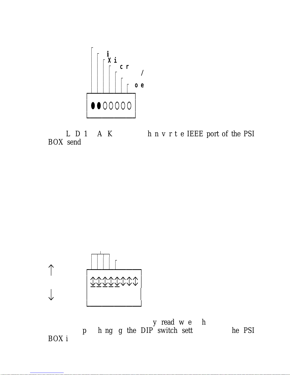
There are two LEDs dedicated to the IEEE port. LED 1
and 2 are used to indicate the flow of data through the IEEE
port.
Page 26 Chapter 3
Page 41
IEEE Port PSI BOX Reference
Figure 3-1. The IEEE Leds.________________________
Ú
Talk
³ Ú
Listen
³ ³ Ú
Xmit
³ ³ ³ Ú
Recvr
³ ³ ³ ³ Ú
Centr O/P
³ ³ ³ ³ ³ Ú
Centr I/P
³ ³ ³ ³ ³ ³ Ú
Power On
³ ³ ³ ³ ³ ³ ³
ЪДДДДДДД¿
³ââ○○○○○³
АДДДДДДДЩ
LED 1, TALK, flashes whenever the IEEE port of the PSI
BOX sends a byte down the IEEE bus. LED 2, LISTEN, flashes
whenever the IEEE port of the PSI BOX accepts a byte from the
IEEE bus, the byte is stored in the PSI BOX internal buffer.
The IEEE DIP Switches._____________________
DIP switches 1-5 on switch block 1, in conjunction with
the MODE switch 7 & 8, are used to set the all the IEEE
options. These options include IEEE address, IEEE controller
mode and source of the IEEE data.
Figure 3-2. The IEEE DIP Switches._______________________________
1-4 IEEE Address
ЪДВБВД¿
³
³ ³ ³ Ú5
IEEE Controller
³ ³ ³ ³ ³
å
on
ЪДДДДДДДД¿
³дддддггг³
æ
off
³
12345678
³
АДДДДДДДДЩ
The DIP switches are only read when the PSI BOX is
powered up. Changing the DIP switch setting whilst the PSI
BOX is running will have no effect.
Chapter 3 Page 27
Page 42

PSI BOX Reference IEEE Port
Setting The IEEE Address.________________________
DIP switches 1-4, on switch block 1, are used to set the
IEEE address of the PSI BOX. When the PSI BOX is acting as
an IEEE device, in modes 1 and 2, the address to which it
responds is determined by the front panel DIP switches. To an
IEEE controller the PSI BOX appears to be two separate
devices, one is an IEEE to RS232 interface, the other an IEEE
to Centronics Parallel interface. The data that the IEEE controller
sends goes to which ever port is being currently addressed. The
RS232 port is as set on the DIP switches, the Centronics port
address is one greater than this.
Figure 3-3. Setting The IEEE Address._________________________________
DIP 1 DIP 2 DIP 3 DIP 4 ADDRESSES SELECTED._____ _____ _____ _____ ___________________
0=Off 0 0 0 0 =RS232 PORT 1 =CENTRONICS PORT
1=On 0 0 0 1 =RS232 PORT 2 =CENTRONICS PORT
0100 2 =RS232 PORT 3 =CENTRONICS PORT
1100 3 =RS232 PORT 4 =CENTRONICS PORT
0010 4 =RS232 PORT 5 =CENTRONICS PORT
1010 5 =RS232 PORT 6 =CENTRONICS PORT
0110 6 =RS232 PORT 7 =CENTRONICS PORT
1110 7 =RS232 PORT 8 =CENTRONICS PORT
0001 8 =RS232 PORT 9 =CENTRONICS PORT
1001 9 =RS232 PORT 10 =CENTRONICS PORT
0101 10 =RS232 PORT 11 =CENTRONICS PORT
1101 11 =RS232 PORT 12 =CENTRONICS PORT
0011 12 =RS232 PORT 13 =CENTRONICS PORT
1011 13 =RS232 PORT 14 =CENTRONICS PORT
0111 14 =RS232 PORT 15 =CENTRONICS PORT
1111 15 =RS232 PORT 16 =CENTRONICS PORT
Setting The Controller State._________________________
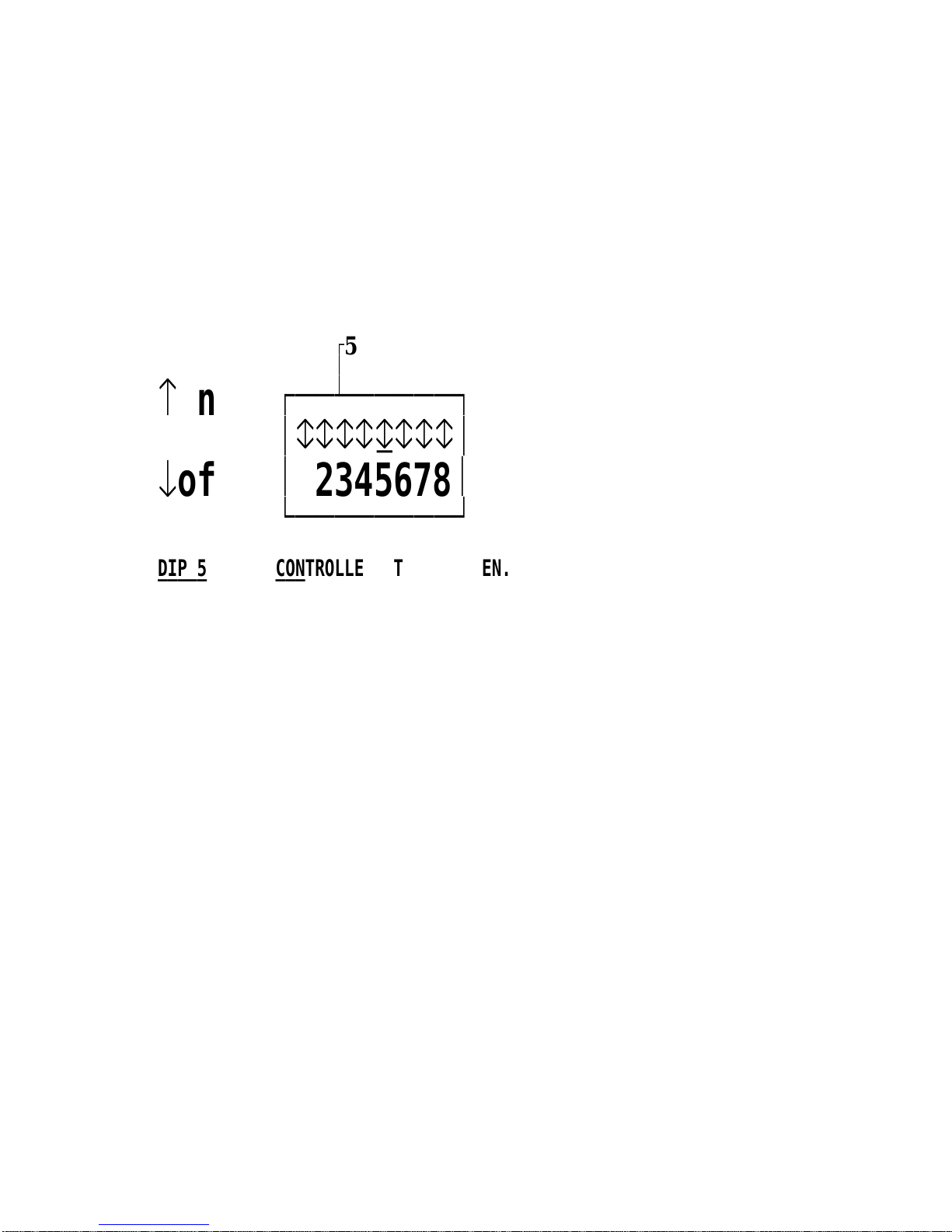
DIP switch 5, on switch block 1, is used to determine
whether the PSI BOX is the IEEE controller or not.
If the PSI BOX is the IEEE controller then you are wanting the
PSI BOX to convert an RS232 or Centronics signal to one
suitable to control some IEEE devices.
If the PSI BOX is not the IEEE controller then you are using an
IEEE computer, say a COMMODORE PET, and you are
Page 28 Chapter 3
Page 43
IEEE Port PSI BOX Reference
wanting the PSI BOX to convert this signal to communicate with
an RS232 and/or a Centronics device
The MODE switches, in conjunction with the IEEE
controller switch, determine the exact PSI configuration in use.
Please refer to the MODE switch settings for more information.
Figure 3-4. The Controller State.____________________________
Ú
5 IEEE Controller
³
³
å
on
ЪДДДДДДДД¿
³ггггдггг³
æ
off
³
12345678
³
АДДДДДДДДЩ
DIP 5 CONTROLLER STATE CHOSEN._____ ________________________
0=Off PSI BOX IS AN IEEE DEVICE
1=On PSI BOX IS THE IEEE CONTROLLER.
IEEE Cables.____________
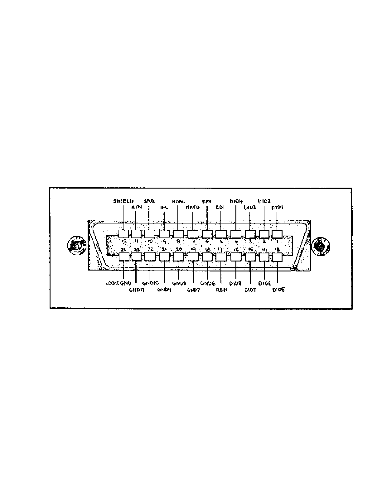
Details of the IEEE port pin outs are given below. The
Connector is a standard IEEE-488 24 pin plug with screw locks.
Any standard commercially available IEEE cable will connect to
the PSI BOX IEEE port. We always have a good range of high
quality R.F.I. shielded cables in stock.
Chapter 3 Page 29
Page 44
PSI BOX Reference IEEE Port
Figure 3-5. The IEEE Port Pin Outs.________________________________
PIN SIGNAL PIN SIGNAL___ ______ ___ ______
1 DATA 1 13 DATA 5
2 DATA 2 14 DATA 6
3 DATA 3 15 DATA 7
4 DATA 4 16 DATA 8
5 EOI 17 REN
6 DAV 18 GROUND 6
7 NRFD 19 GROUND 7
8 NDAC 20 GROUND 8
9 IFC 21 GROUND 9
10 SRQ 22 GROUND 10
11 ATN 23 GROUND 11
12 SHIELD 24 SHIELD
Page 30 Chapter 3
Page 45

Parallel Port PSI BOX Reference
CHAPTER 4
THE
CENTRONICS
PARALLEL
PORT.
Introduction.____________
This chapter describes the Centronics parallel port on the
PSI BOX. The parallel port connector pin outs, the function of
the Centronics Output DIP switch and the Centronics LEDs, the
parallel port input and output handshake are all explained in
detail.
Summary._________
The Centronics Parallel port is an IBM PC printer
compatible port, it provides TTL logic level signals. The
connector has the same pin out as the IBM PC parallel port
LPT1: etc. A 25 way female D connector, with screw locks for
secure connections, is used. The port may be either an input or
an output. A front panel LED flashes whenever the Centronics
port sends a byte. A front panel LED flashes whenever the
Centronics port receives a byte.
The Centronics Parallel port is normally used to drive a
parallel printer. When used as an input it can receive the output
from a computers parallel printer port and so act as the input for
a parallel to RS232 or parallel to IEEE interface.
Chapter 4 Page 31
Page 46
PSI BOX Reference Parallel Port
Unlike the two other ports, the Centronics Parallel port is
NOT bidirectional. It can act EITHER as an input OR as an
output. It can not change over in mid stream from input to
output or vice versa.
Centronics Leds._______________
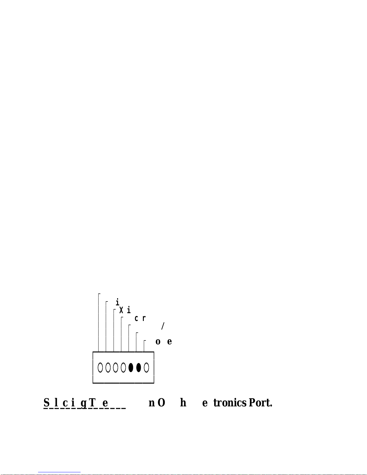
There are two LEDs dedicated to the Centronics Parallel
port. LED 5 and 6 are used to indicate the flow of data to the
Centronics Parallel port.
LED 5, CENTR O/P, flashes whenever the Centronics
Parallel port of the PSI BOX sends a byte, from its buffer, to
the parallel bus.
LED 4, CENTR I/P flashes whenever the Centronics
Parallel port of the PSI BOX receives a byte from the printer
port of a computer, the byte is stored in the PSI BOX internal
buffer.
Since the Centronics port is either an input OR an output
only one of these LEDs will be in use for the particular PSI
BOX configuration chosen.
Figure 4-1. The Centronics Leds._____________________________
Ú
Talk
³ Ú
Listen
³ ³ Ú
Xmit
³ ³ ³ Ú
Recvr
³ ³ ³ ³ Ú
Centr O/P
³ ³ ³ ³ ³ Ú
Centr I/P
³ ³ ³ ³ ³ ³ Ú
Power On
³ ³ ³ ³ ³ ³ ³
ЪДДДДДДД¿
³○○○○ââ○³
АДДДДДДДЩ
Selecting The Direction Of The Centronics Port.__________________________________________
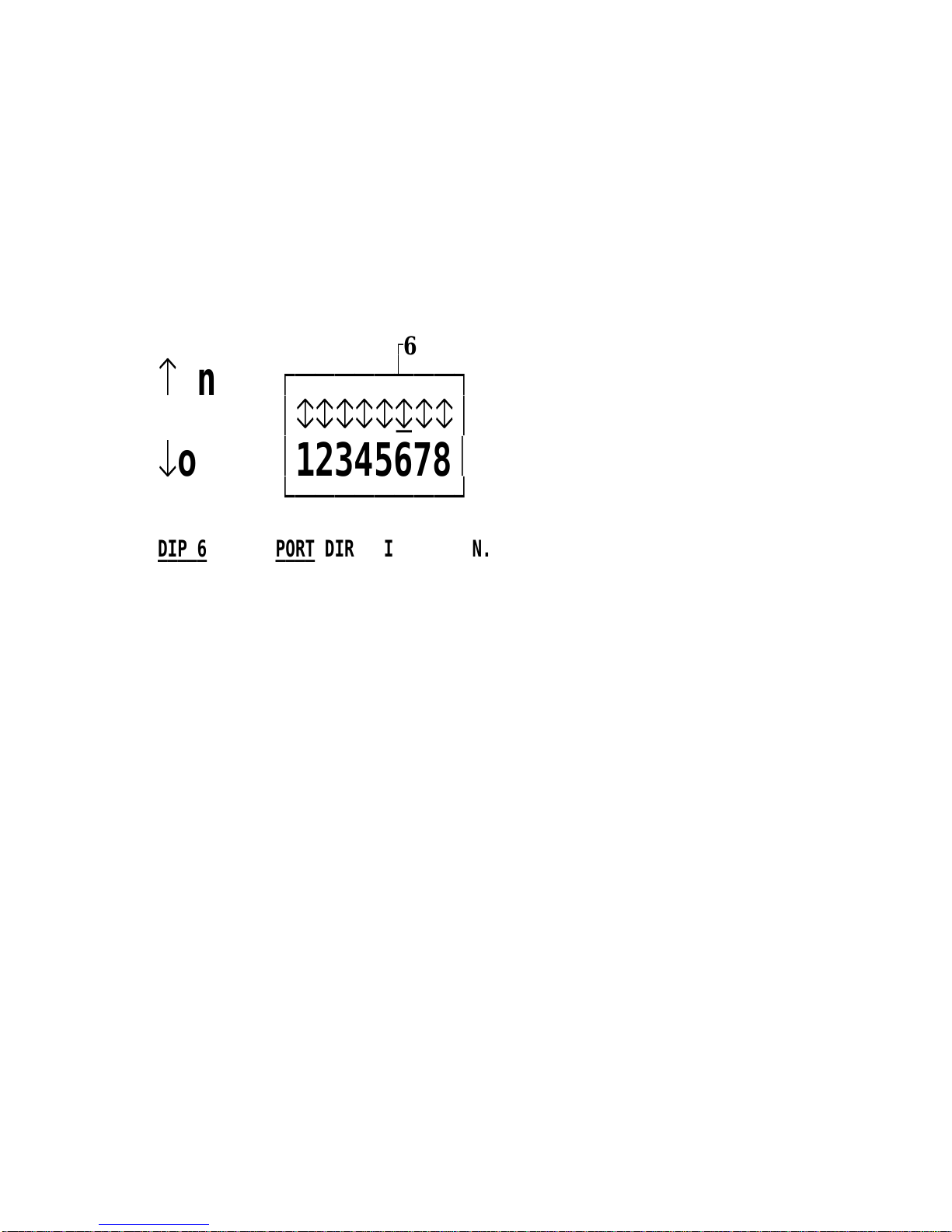
DIP switch 6 on switch block 1 is used to determine
whether the Centronics Parallel port is an input or an output.
Page 32 Chapter 4
Page 47
Parallel Port PSI BOX Reference
When used as an input, it can receive the output from a
computers parallel printer port and so act as the input for a
parallel to RS232 or parallel to IEEE interface.
When used an an output, the Centronics Parallel port is
normally used to drive a parallel printer.
Figure 4-2. Setting Parallel Port Direction._____________________________________
Ú
6 Centronic O/P
³
å
on
ЪДДДДДДДД¿
³гггггдгг³
æ
off
³
12345678
³
АДДДДДДДДЩ
DIP 6 PORT DIRECTION CHOSEN._____ ______________________
0=Off Centronics Port INPUT.
1=On Centronics Port OUTPUT.
The Centronics Output Handshake._______________________________
The Centronics port output handshake is as follows.
A) If the Centronics printer is busy, it should raise the BUSY
line true. The PSI BOX will not send any data out of the
Centronics port if the BUSY INPUT is high.
B) When the BUSY INPUT line to the PSI BOX is low then
the PSI BOX will send any data in its buffer to the
Centronics port.
The PSI BOX places the first byte on the DATA 0-7 lines.
The PSI BOX allows the data lines to stabilise.
C) Then the PSI BOX toggles the STROBE line low, for a
minimum of 1 microsecond. The Centr o/p LED flashes.
D) The printer will respond by setting the BUSY line true,
high, and will read the data off the data bus.
Chapter 4 Page 33
Page 48

PSI BOX Reference Parallel Port
E) When ready to receive another byte from the PSI BOX the
printer sets BUSY low and toggles the ACKNOWLEDGE
line low. The PSI BOX will maintain valid data on the
data bus for a minimum of 1 microsecond after the
STROBE line goes high. Later the printer sets BUSY low
and toggles the ACKNOWLEDGE line low, for a
minimum of 1 microsecond.
F) The handshake starts again.
The Centronics Input Handshake.______________________________
The Centronics port input handshake, which has been
improved to cope woth screen dumps via Shift-PrtScr from the
latest breed of fast 386 & 486 PCs, is as follows.
A) If the PSI BOX is busy or if its Centronics input buffer is
full, it will raise the BUSY line true. Any data that is sent
to the PSI BOX while the BUSY line is high is LOST!
Even though the Centr i/p LED may flash.
B) When the Centronics device senses that the PSI BOX has
set the BUSY line low, it puts data on the data bus.
C) The Centronics device signals the PSI BOX by toggling
the STROBE line low, for a minimum of 1 microsecond.
D) The PSI BOX will respond by setting the BUSY line true,
high, and will read the data off the data bus.
E) When ready to receive another byte the PSI BOX sets
BUSY low and toggles the ACKNOWLEDGE line low,
for a minimum of 1 microsecond. If the PSI BOX input
buffer becomes full then it will keep BUSY high and will
not sent ACKNOWLEDGE until the buffer is emptied.
F) The handshake starts again.
Page 34 Chapter 4
Page 49
Parallel Port PSI BOX Reference
Chapter 4 Page 35
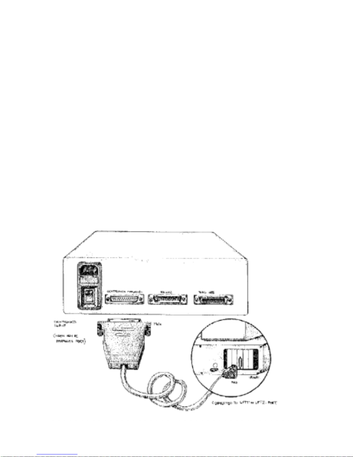
Centronics Cables.
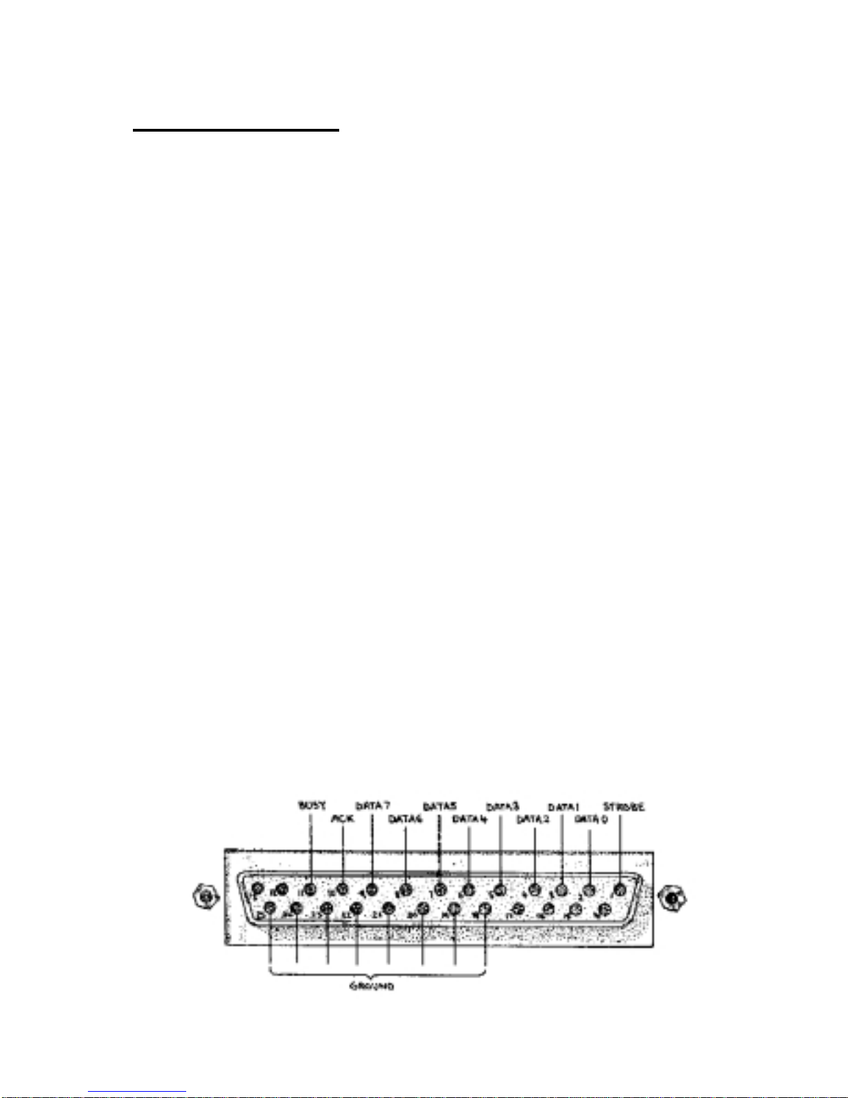
When used as an output the Centronics port can driv e a parallel
printer. A standard IBM PC parallel printer cable can be used to
connect the PSI BOX parallel port to the printer. When used as an
input the PSI BOX parallel port can receive data from the parallel
printer port of a computer. To drive the PSI BOX from the LPT1:
port of an IBM PC, make up a cable as follows. A simple straight
through cable with male-to-male 25 pin D connectors as shown in
figure 4-4 is all that is required. Since in the PSI BOX the PE line,
pin12, is pulled low and /ERROR line, pin 15 and the SELECT
line, pin 13 are pulled high the PSI BOX emulates a printer port
correctly.
Figure 4-3 The Centronics Output Port Pin Outs.
PIN SIGNAL DIRECTION
1 STROBE OUTPUT FROM PSI BOX
2 DATA 0 OUTPUT FROM PSI BOX
3 DATA 1 OUTPUT FROM PSI BOX
4 DATA 2 OUTPUT FROM PSI BOX
5 DATA 3 OUTPUT FROM PSI BOX
6 DATA 4 OUTPUT FROM PSI BOX
7 DATA 5 OUTPUT FROM PSI BOX
8 DATA 6 OUTPUT FROM PSI BOX
9 DATA 7 OUTPUT FROM PSI BOX
10 ACKNOWLEDGE INPUT TO PSI BOX
11 BUSY INPUT TO PSI BOX
12-17 NO CONNECTION
18-25 GROUND
Page 50
Parallel Port PSI BOX Reference
Chapter 4 Page 36
Figure 4-4. The Centronics Input P ort Pin Outs.
PIN SIGNAL DIRECTION
1 STROBE INPUT TO PSI BOX
2 DATA 0 INPUT TO PSI BOX
3 DATA 1 INPUT TO PSI BOX
4 DATA 2 INPUT TO PSI BOX
5 DATA 3 INPUT TO PSI BOX
6 DATA 4 INPUT TO PSI BOX
7 DATA 5 INPUT TO PSI BOX
8 DATA 6 INPUT TO PSI BOX
9 DATA 7 INPUT TO PSI BOX
10 ACKNOWLEDGE OUTPUT FROM PSI BOX
11 BUSY OUTPUT FROM PSI BOX
12 PE OUTPUT FROM PSI BOX PULLED to Ground
13 SELECT OUTPUT FROM PSI BOX PULLED HIGH NEW LINE
15 /ERROR OUTPUT FROM PSI BOX PULLED HIGH NEW LINE
14, 16-17 NO CONNECTION
18-25 GROUND
Figure 4-5. Centronics Input From PC Printer Port.
Page 51

RS232 Port PSI BOX Reference
CHAPTER 5
THE RS232
SERIAL PORT.
Introduction.____________
This chapter describes the RS232 port on the PSI BOX.
The RS232 serial port connector pin outs, the function of the
DIP switches and LEDs, how to set the baud rate, parity and
RS232 handshake options are explained in detail. Details of how
to connect the PSI BOX to both an IBM PC and a modem are
included.
Summary._________
The RS232 port signals are the industry standard +/- 12
Volt level. The serial port is an IBM PC serial compatible port.
The connector has the same pin outs as the IBM PC serial port
COM1: etc. A 25 way male D connector, with screw locks for
secure connections, is used.
The serial port is bi-directional. The baud rate and parity
options are selectable from the front panel. Baud rates between
75 to 19200 baud are available. Parity may be off or on, even or
odd. The may be either 7 or 8 data bits per word. A front panel
LED flashes whenever the RS232 port sends a byte. A front
panel LED flashes whenever the RS232 port receives a byte.
The RS232 port lines are implemented with the PSI BOX
as the Data Terminal Equipment, DTE. The PSI BOX can be
used for asynchronous communications only. It is not for
synchronous communications.
Chapter 5 Page 37
Page 52
PSI BOX Reference RS232 Port
RS232 Leds.___________
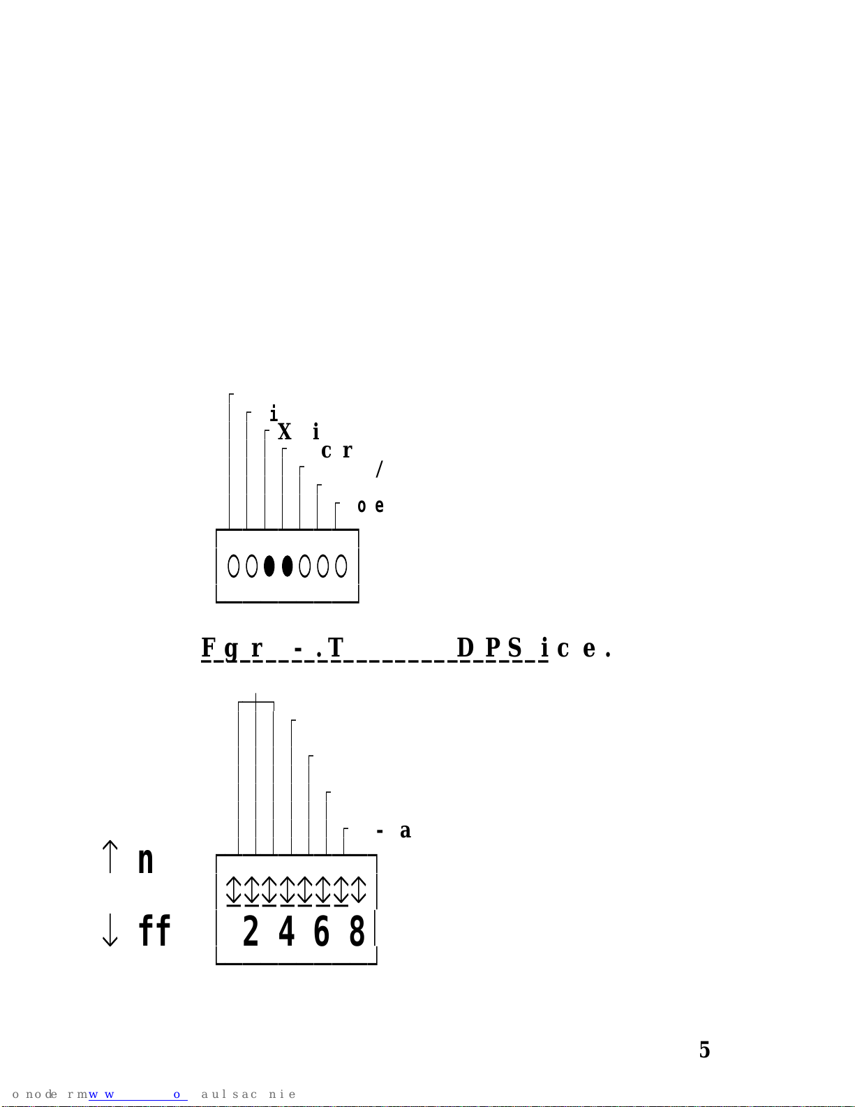
There are two LEDs dedicated to the RS232 port. LED 3
and 4 are used to indicate the flow of data to the RS232 port.
LED 3, XMIT, flashes whenever the RS232 port of the
PSI BOX sends a byte, from its buffer, to the serial bus.
LED 4, RCVR, flashes whenever the RS232 port of the
PSI BOX receives a byte from the serial bus, the byte is stored
in the PSI BOX internal buffer.
Figure 5-1. The RS232 Leds. _________________________
Ú
Talk
³ Ú
Listen
³ ³ Ú
Xmit
³ ³ ³ Ú
Recvr
³ ³ ³ ³ Ú
Centr O/P
³ ³ ³ ³ ³ Ú
Centr I/P
³ ³ ³ ³ ³ ³ Ú
Power On
³ ³ ³ ³ ³ ³ ³
ЪДДДДДДД¿
³○○ââ○○○³
АДДДДДДДЩ
Figure 5-2. The RS232 DIP Switches.________________________________
1-3 Baud Rate
ÚÄÅÄ¿
³
³ ³
Ú
4 Xon Xoff
³ ³ ³ ³
³
³ ³ ³
Ú
5 Parity Enable
³ ³ ³ ³ ³
³
³ ³ ³ ³
Ú
6 Parity Even
³ ³ ³ ³ ³ ³
³
³ ³ ³ ³ ³
Ú
7 7-Data Bits
³ ³ ³ ³ ³ ³ ³
å
on
ЪДДДДДДДД¿
³дддддддг³
æ
off
³
12345678
³
АДДДДДДДДЩ
Page 38 Chapter 5
Page 53
RS232 Port PSI BOX Reference
The RS232 DIP Switches.______________________
DIP switches 1-7 on switch block 2 are used to set the all
the RS232 options. These options include baud rate, handshake
type, parity options and data word length.
The DIP switches are only read when the PSI BOX is
powered up. Changing the DIP switch setting whilst the PSI
BOX is running will have no effect.
Setting The Baud Rate.____________________
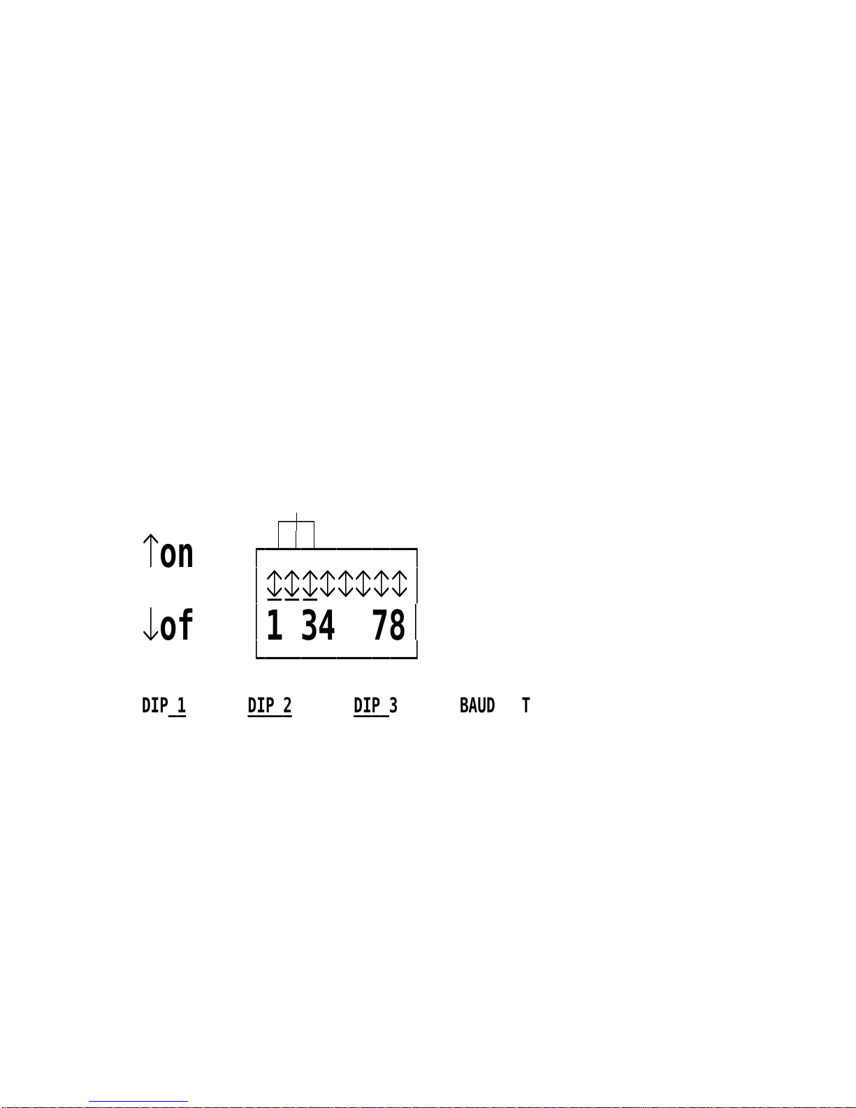
DIP switches 1-3 on switch block 2 are used to set the
RS232 baud rate. The range of baud rates is 75 - 19200 baud.
Figure 5-3. Baud Rate Settings.___________________________
1-3 Baud Rate
ÚÄÅÄ¿
³
³
³
å
on
ЪДДДДДДДД¿
³дддггггг³
æ
off
³
12345678
³
АДДДДДДДДЩ
DIP 1 DIP 2 DIP 3 BAUD RATE SET_____ _____ _____ _____________
0=Off 0 0 75 BAUD
1=On 0 0 150 BAUD
0 1 0 300 BAUD
1 1 0 1200 BAUD
0 0 1 2400 BAUD
1 0 1 4800 BAUD
0 1 1 9600 BAUD
1 1 1 19200 BAUD
The RS232 Handshake._____________________
DIP switch 4 on switch block 2 is used to select the type
of RS232 handshake required.
Chapter 5 Page 39
Page 54
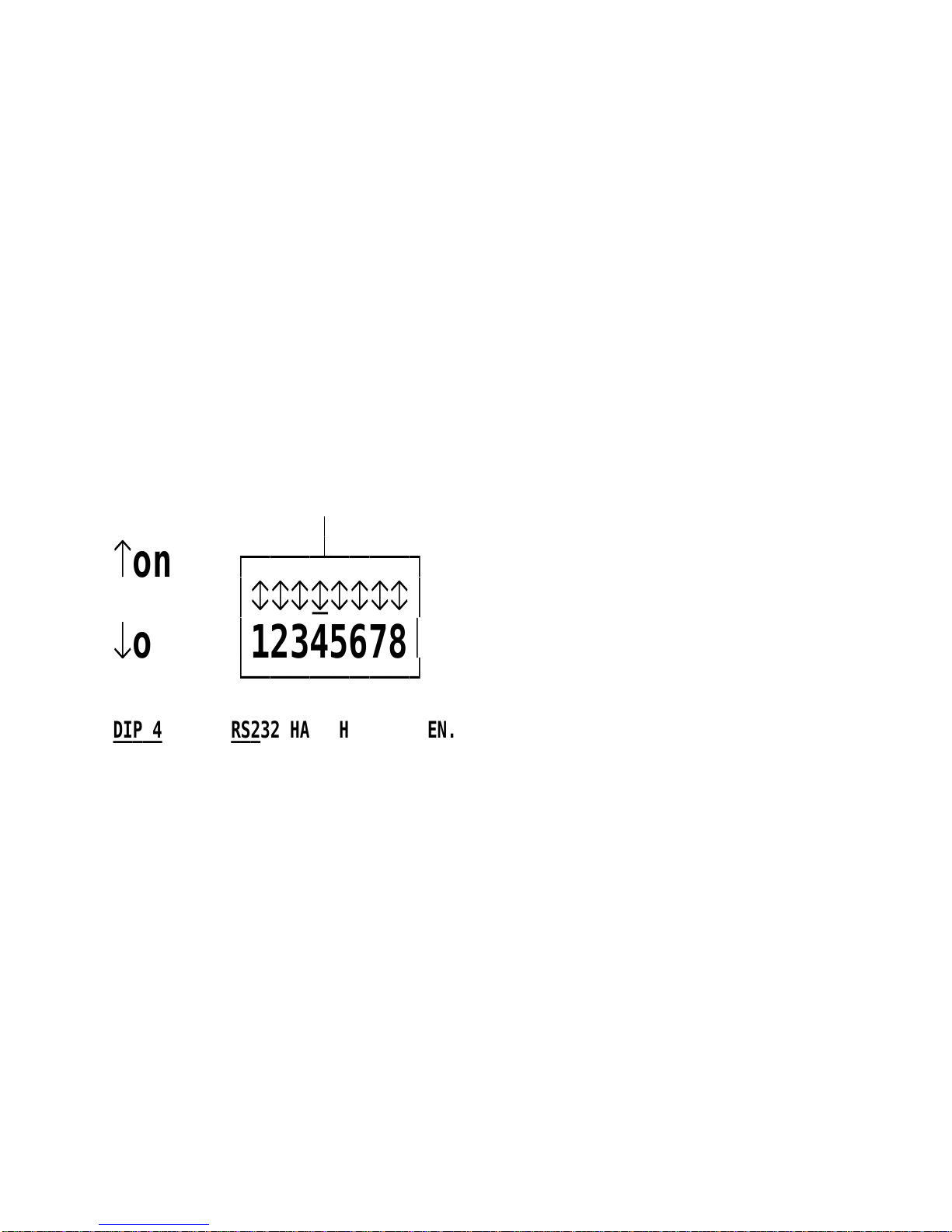
PSI BOX Reference RS232 Port
When the switch is OFF the flow of data is dependent on
the state of the DTR, RTS and CTS, DSR and DCD signals,
only. This is the hard wired handshake.
When the switch is ON the handshake is conducted in
software, the flow of data is controlled by the sending and
receiving of the XON and XOFF codes. The handshake lines
DTR and RTS are still set true, but the PSI BOX ignores the
state of the CTS, DSR and DCD signal inputs and the data flow
will be controlled by the XON/ XOFF codes in the data stream.
This allows communication without data loss or tears using only
3 wires (TxD, RxD and ground).
Figure 5-4. Selecting The RS232 Handshake._______________________________________
4 Xon Xoff
³
³
å
on
ЪДДДДДДДД¿
³гггдгггг³
æ
off
³
12345678
³
АДДДДДДДДЩ
DIP 4 RS232 HANDSHAKE CHOSEN._____ _______________________
0=Off DTR, RTS AND CTS, DSR, DCD HARD WIRED HANDSHAKE
1=On XON/ XOFF SOFTWARE HANDSHAKE.
The Hard Wired Handshake._________________________
The hard wired handshake works in the following manner.
DTR and RTS are outputs from the PSI BOX. CTS, DSR
and DCD are inputs to the PSI BOX.
When the PSI BOX sets is powered on it sets RTS out
true, indicating that it is present and on line. DTR is also set out
true indicating that the PSI BOX is ready to receive data. No
data is transmitted from the PSI BOX unless CTS, DSR and
DCD are input true.
Page 40 Chapter 5
Page 55

RS232 Port PSI BOX Reference
The PSI BOX sets DTR out low when it is ready to
receive data. When the PSI BOX input buffer starts to fill up,
less than 128 bytes left (or only 1 if no buffer), it will set DTR
out false, this will be detected by the CTS input of the other
device. If it continues to receive data it will hold DTR out false,
the data received may be lost if there is no room in the PSI
BOX buffer. Any data received when DTR or RTS are high
high may be LOST, even if the RS232 RCVR LED flashes!
When there is more than 128 bytes of room in the PSI BOX
buffer, the PSI BOX will set DTR out true. It will remain true
provided their is still, at least, 128 bytes of space available in its
internal buffer.
The XON/ XOFF Handshake.__________________________
The XON/ XOFF handshake works in the following
manner. The output lines DTR and RTS are sent out low, and
the PSI BOX does not care what state the CTS, DSR and DCD
inputs are.
It is recommended that if you are using the XON/ XOFF
handshake that the CTS, DSR and DCD inputs to the PSI BOX
are forced true.
The flow of data is governed by the sending and receipt of
the XON XOFF codes. The XON code is chr$(17), the XOFF
code is chr$(19).
When ever the PSI BOX receives XOFF, it will
immediately stop sending data until after it has received an XON
code.
The PSI BOX sends the XOFF code when it is about to
run out of room in which to store incoming data. The minimum
amount left before the transmission of the XOFF code depends
on whether the 32K buffer is enabled or not.
XON XOFF Buffer In Use.________________________
When the PSI BOX input buffer starts to fill up, less than
128 bytes left, it will send an XOFF code to the other device. If
Chapter 5 Page 41
Page 56
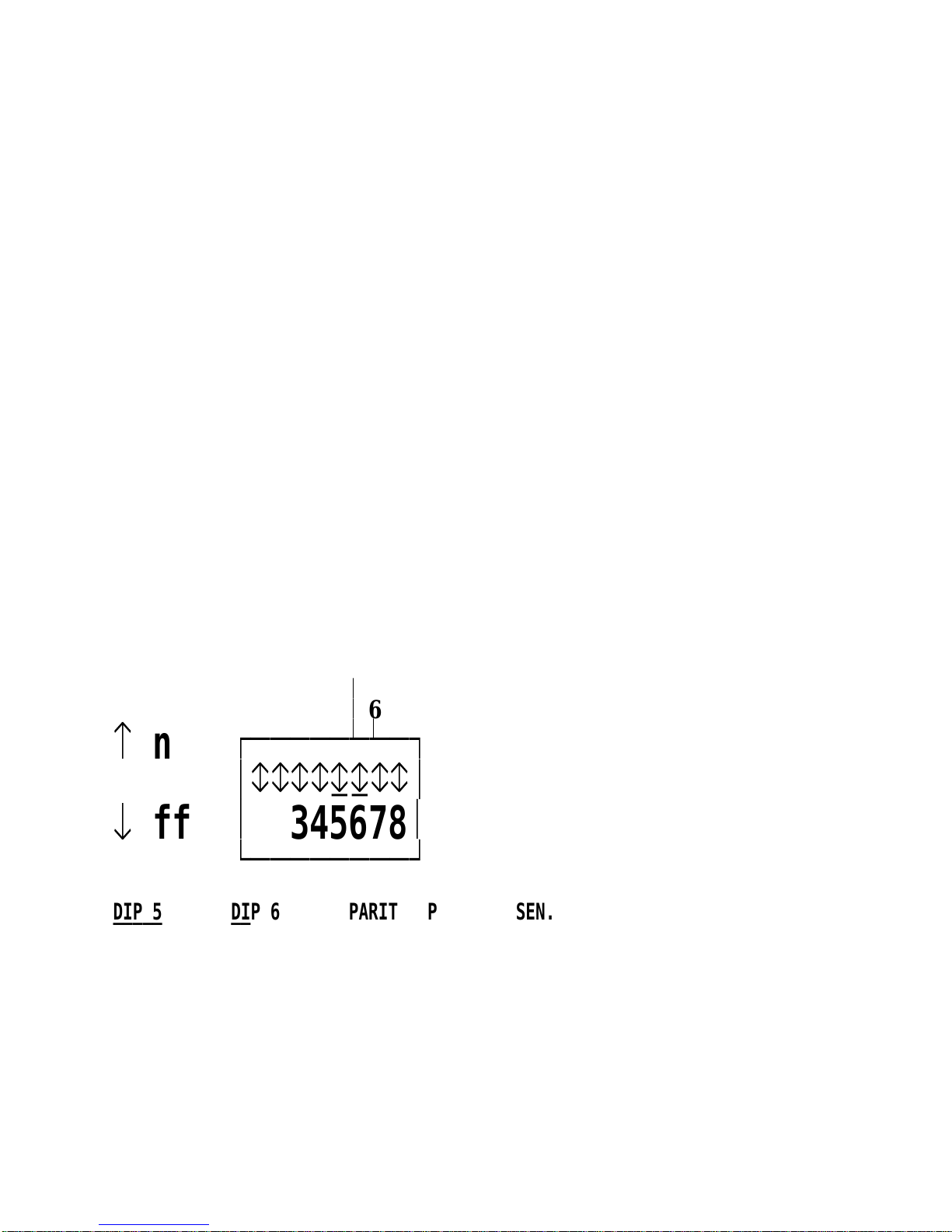
PSI BOX Reference RS232 Port
it continues to receive data it will send further XOFF codes to
the device, the data received may be lost if there is no room in
the PSI BOX buffer. When there is more than 128 bytes of
room in the PSI BOX buffer, the PSI BOX will transmit the
XON code.
XON XOFF Buffer Disabled.__________________________
When the PSI BOX is used with the buffer disabled it can
only store one byte before it is full. After each RS232 byte is
received it will send an XOFF code to the other device. If it
continues to receive data it will send further XOFF codes to the
device, the data received will be lost since there is no room in
the PSI BOX buffer. When there RS232 input buffer is emptied
by an IEEE computer reading it the PSI BOX will transmit the
XON code, so signalling the RS232 device that it is ready to
accept the next byte.
Figure 5-5. Parity Option._______________________
5 Parity Enable
³
³
6 Parity Even
³ ³
å
on
ЪДДДДДДДД¿
³ггггддгг³
æ
off
³
12345678
³
АДДДДДДДДЩ
DIP 5 DIP 6 PARITY OPTION CHOSEN._____ _____ _____________________
0=Off 0 NO PARITY
1=On 0 ODD PARITY
0 1 NO PARITY
1 1 EVEN PARITY
Page 42 Chapter 5
Page 57
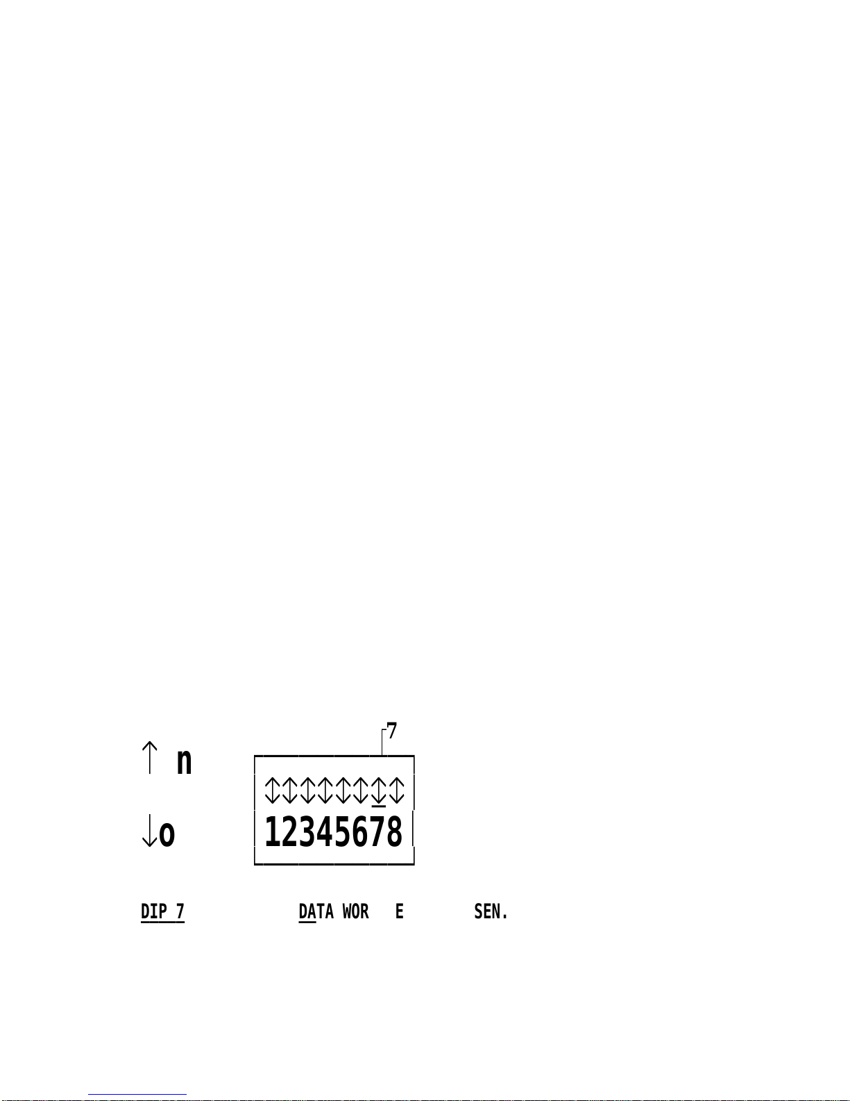
RS232 Port PSI BOX Reference
Setting The Parity Options.________________________
DIP switches 5 and 6 on switch block 2 are used to set the
RS232 parity options. The parity may be enabled (on) or
disabled (off), when parity is enabled then the parity bit sent
may be either even parity or odd parity.
RS232 Stop Bits._______________
The number of stop bits sent by the PSI BOX is
determined by the parity and data word length chosen.
No Parity.
2 STOP bits are always sent.
Parity Enabled.
7 data bits gives 2 STOP bits.
8 data bits gives 1 STOP bit.
Setting The Data Word Length.____________________________
DIP switch 7 on switch block 2 is used to set the RS232
data word length. The data word may be either 7 or 8 bits long.
Figure 5-6. The Data Word Length._______________________________
Ú
7 7-Data Bits
³
å
on
ЪДДДДДДДД¿
³ггггггдг³
æ
off
³
12345678
³
АДДДДДДДДЩ
DIP 7 DATA WORD LENGTH CHOSEN._____ ________________________
0=Off 8 BITS
1=On 7 BITS
Chapter 5 Page 43
Page 58

PSI BOX Reference RS232 Port
RS232 Port Cables._________________
The RS232 port is the middle port on the back panel of
the PSI BOX. To connect to the PSI BOX RS232 port you will
need a cable terminating in a 25 way female D connector. It is a
sound practice to use cables with screws fitted that will allow
you to fasten the cable securely to the PSI BOX.
In general, you will need to make up a "cross over" cable
to correctly interface the PSI BOX to the RS232 port of another
computer.
Traditionally, making up the cross over cable has been
considered a black art. However, provided you have the pin outs
and handshake requirements of both sides of your RS232
connection, the cross over cable becomes a matter of common
sense.
The cross over cable is simply to ensure that the right
signals going out of one RS232 port go into the appropriate lines
of the other RS232 port.
Connecting To An IBM PC Serial Port.__________________________________
Suppose we want to connect the PSI BOX to the serial
port of an IBM PC. See Figures 5-12, 5-13 and 5-14.
1) Connect up the earth lines.
Lines 1 & 7 of the PSI BOX to lines 1 & 7 of the PC.
This gives the two devices a common earth level.
2) Connect the Transmit and Receive lines together.
Line 2, TxD, of the PSI goes to line 3, RxD, of the PC.
Line 3, RxD, of the PSI goes to line 2, TxD, of the PC.
So each receives the data transmitted by the other.
3) Connect up the PSI DTR line, pin 20 to the PC DCD, pin
8 and CTS, pin 5, lines.
Also, connect up the PC DTR line, pin 20 to the PSI
DCD, pin 8 and CTS, pin 5, lines.
This allows the receiving device to signal when it can no
longer accept data. The receiving device sets DTR false
Page 44 Chapter 5
Page 59
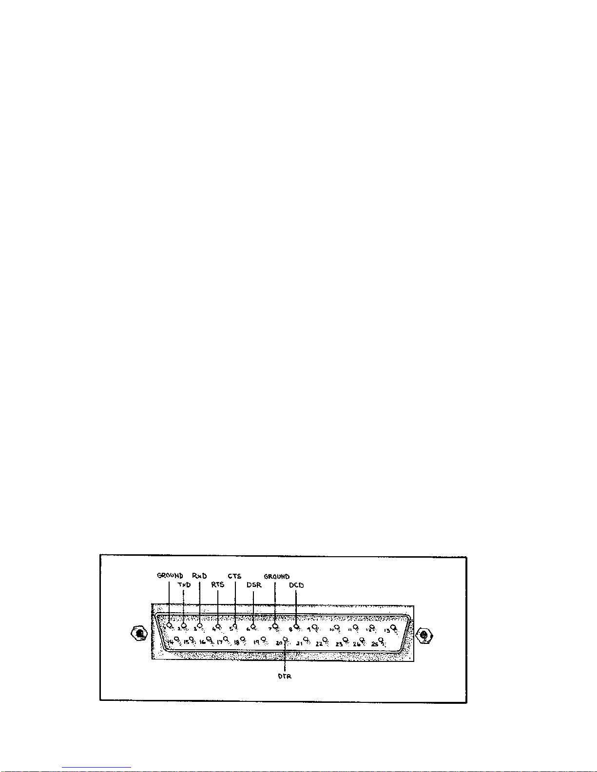
RS232 Port PSI BOX Reference
when it it is unable to receive any more data. The sending
device reads DTR on its CTS and DCD pins. It should
stop sending when CTS goes false.
4) Connect the PSI RTS pin 4, to the PC DSR line, pin 6.
Also, connect up the PC RTS line, pin 4, to the PSI DSR
line, pin 6.
This RTS line is used to let the other device know that it
is ready for data exchange.
Connecting To A Modem._______________________
If you are connecting a MODEM to the PSI BOX then
you will not need a cross over cable and a straight through cable
connecting pins 1-8 and 20 is all that is required.
Figure 5-7. The RS232 Port Pin Outs.________________________________
PIN SIGNAL DIRECTION___ ______ _________
1 GROUND N/A
2 TxD TRANSMITTED DATA OUTPUT FROM PSI BOX
3 RXD RECEIVED DATA INPUT TO PSI BOX
4 RTS REQUEST TO SEND OUTPUT FROM PSI BOX
5 CTS CLEAR TO SEND INPUT TO PSI BOX
6 DSR DATA SET READY INPUT TO PSI BOX
7 GROUND N/A
8 DCD DATA CARRIER DETECT INPUT TO PSI BOX
20 DTR DATA TERMINAL READY OUTPUT FROM PSI BOX
9-19 NO CONNECTION
21-25 NO CONNECTION
Chapter 5 Page 45
Page 60
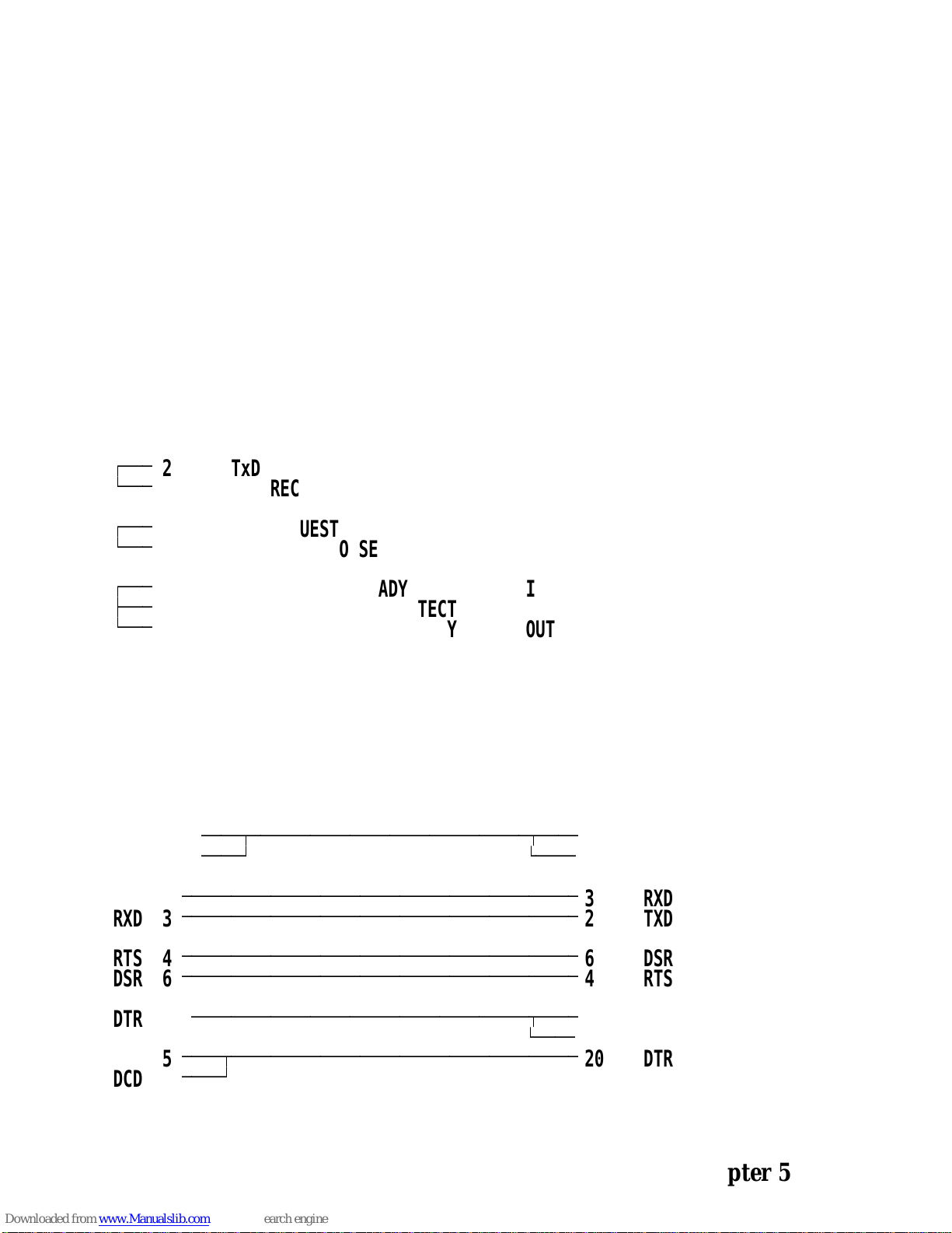
PSI BOX Reference RS232 Port
Loop Back Connector.____________________
A loop back connector can be used to echo RS232 data
transmitted by the PSI BOX back into the RS232 receiver. This
is of use in Mode 1 and 2 when data written to the PSI BOX
can be read back by the IEEE controller. In this way the
function of the serial port can be tested.
A loop back connector is a female 25 pin D connector that
has the three groups of signals shorted together as in Figure 5-8.
Figure 5-8. The Loop Back Connector._________________________________
PIN SIGNAL DIRECTION___ ______ _________
ÚÄÄÄ
2 TxD TRANSMITTED DATA OUTPUT FROM PSI BOX
ÀÄÄÄ
3 RXD RECEIVED DATA INPUT TO PSI BOX
ÚÄÄÄ
4 RTS REQUEST TO SEND OUTPUT FROM PSI BOX
ÀÄÄÄ
5 CTS CLEAR TO SEND INPUT TO PSI BOX
ÚÄÄÄ
6 DSR DATA SET READY INPUT TO PSI BOX
ÃÄÄÄ
8 DCD DATA CARRIER DETECT INPUT TO PSI BOX
ÀÄÄÄ
20 DTR DATA TERMINAL READY OUTPUT FROM PSI BOX
Figure 5-9. PSI Box To PC Serial Port Cable._______________________________________
PSI BOX SERIAL PORT Side IBM PC SERIAL PORT Side.________________________ ________________________
USE 25 Pin Female D Connector 25 Pin Female D Connector_____________________________ _________________________
SIGNAL PIN PIN SIGNAL______ ___ ___ ______
GROUND 1
ДДДДВДДДДДДДДДДДДДДДДДДДДДДДДДДДДВДДДД
1 GROUND
GROUND 7
ДДДДЩ АДДДД
7 GROUND
TXD 2
ДДДДДДДДДДДДДДДДДДДДДДДДДДДДДДДДДДДДДДДД
3 RXD
RXD 3
ДДДДДДДДДДДДДДДДДДДДДДДДДДДДДДДДДДДДДДДД
2 TXD
RTS 4
ДДДДДДДДДДДДДДДДДДДДДДДДДДДДДДДДДДДДДДДД
6 DSR
DSR 6
ДДДДДДДДДДДДДДДДДДДДДДДДДДДДДДДДДДДДДДДД
4 RTS
DTR 20
ДДДДДДДДДДДДДДДДДДДДДДДДДДДДДДДДДДВДДДД
8 DCD
АДДДД
5 CTS
CTS 5
ДДДДВДДДДДДДДДДДДДДДДДДДДДДДДДДДДДДДДДДД
20 DTR
DCD 8
ДДДДЩ
Page 46 Chapter 5
Page 61
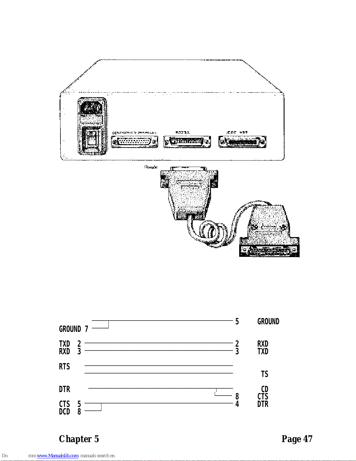
RS232 Port PSI BOX Reference
Figure 5-10. Connecting To The RS232 Port._______________________________________
Figure 5-11. PSI Box To AT Serial Port Cable.________________________________________
PSI BOX SERIAL PORT Side IBM PC SERIAL PORT Side.________________________ ________________________
USE 25 Pin Female D Connector 9 Pin Female D Connector_____________________________ ________________________
SIGNAL PIN PIN SIGNAL______ ___ ___ ______
GROUND 1
ДДДДВДДДДДДДДДДДДДДДДДДДДДДДДДДДДДДДДД
5 GROUND
GROUND 7
ДДДДЩ
TXD 2
ДДДДДДДДДДДДДДДДДДДДДДДДДДДДДДДДДДДДДДДД
2 RXD
RXD 3
ДДДДДДДДДДДДДДДДДДДДДДДДДДДДДДДДДДДДДДДД
3 TXD
RTS 4
ДДДДДДДДДДДДДДДДДДДДДДДДДДДДДДДДДДДДДДДД
6 DSR
DSR 6
ДДДДДДДДДДДДДДДДДДДДДДДДДДДДДДДДДДДДДДДД
7 RTS
DTR 20
ДДДДДДДДДДДДДДДДДДДДДДДДДДДДДДДДДДВДДДД
1 DCD
АДДДД
8 CTS
CTS 5
ДДДДВДДДДДДДДДДДДДДДДДДДДДДДДДДДДДДДДДДД
4 DTR
DCD 8
ДДДДЩ
Chapter 5 Page 47
Page 62
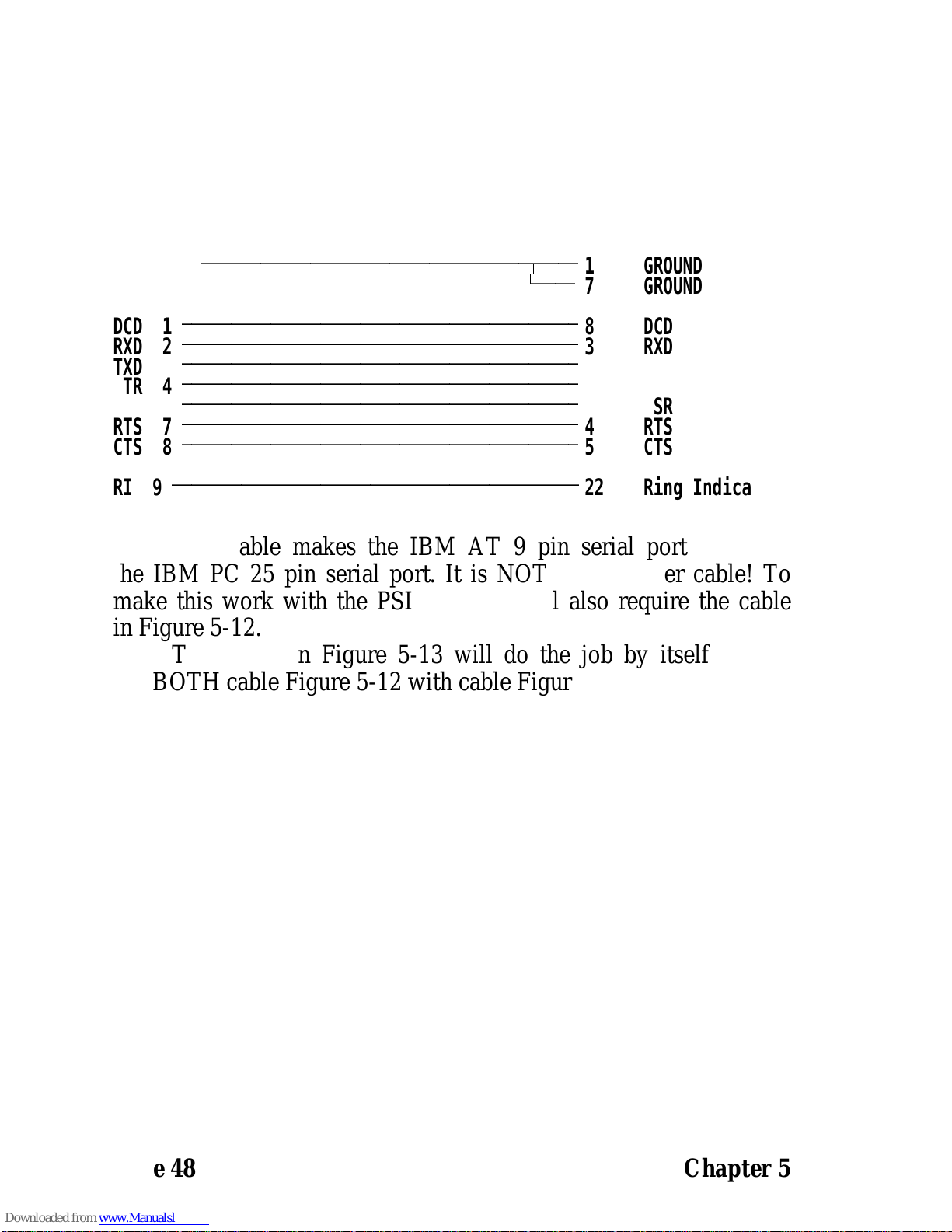
PSI BOX Reference RS232 Port
Figure 5-12. IBM AT To PC Serial Port Cable.________________________________________
IBM AT SERIAL PORT Side IBM PC SERIAL PORT Side._______________________ ________________________
USE 9 Pin Female D Connector 25 Pin Male D Connector____________________________ _______________________
SIGNAL PIN PIN SIGNAL______ ___ ___ ______
GROUND 5
ДДДДДДДДДДДДДДДДДДДДДДДДДДДДДДДДДВДДДД
1 GROUND
АДДДД
7 GROUND
DCD 1
ДДДДДДДДДДДДДДДДДДДДДДДДДДДДДДДДДДДДДДДД
8 DCD
RXD 2
ДДДДДДДДДДДДДДДДДДДДДДДДДДДДДДДДДДДДДДДД
3 RXD
TXD 3
ДДДДДДДДДДДДДДДДДДДДДДДДДДДДДДДДДДДДДДДД
2 TXD
DTR 4
ДДДДДДДДДДДДДДДДДДДДДДДДДДДДДДДДДДДДДДДД
20 DTR
DSR 6
ДДДДДДДДДДДДДДДДДДДДДДДДДДДДДДДДДДДДДДДД
6 DSR
RTS 7
ДДДДДДДДДДДДДДДДДДДДДДДДДДДДДДДДДДДДДДДД
4 RTS
CTS 8
ДДДДДДДДДДДДДДДДДДДДДДДДДДДДДДДДДДДДДДДД
5 CTS
RI 9
ДДДДДДДДДДДДДДДДДДДДДДДДДДДДДДДДДДДДДДДДД
22 Ring Indicator.
This cable makes the IBM AT 9 pin serial port look like
the IBM PC 25 pin serial port. It is NOT a cross over cable! To
make this work with the PSI Box you will also require the cable
in Figure 5-12.
The Cable in Figure 5-13 will do the job by itself or else
use BOTH cable Figure 5-12 with cable Figure 5-14
Page 48 Chapter 5
Page 63

Modes 1-6 & 8. PSI BOX Reference
CHAPTER 6
THE PSI BOX
MODE 1-6 & 8
Introduction.____________
This chapter explains, in detail, the 8 PSI BOX operating
modes, the DIP switch settings used to select each mode, the
exact nature of the data transfer and applications of each mode.
The Mode Switches.__________________
The mode switches determine the type of data conversion
the PSI BOX is to perform and specify which port is supplying
data and which is accepting data. DIPs 5, 6, 7 & 8 on switch
block 1 are the mode control switches.
The IEEE Controller switch, DIP 5, and the Centronics
O/P switch, DIP 6, are mode switches which have a dedicated
role. DIP switches 7 & 8 on switch block 1 have no dedicated
function but are used in conjunction with the DIPs 5 & 6 to
define the mode of operation of the PSI BOX.
With the exception of the Pet to Ascii character
conversion, the DIP switches are only read when the PSI BOX
is powered up. Changing the DIP switch setting whilst the PSI
BOX is running will have no effect. If you wish to change the
mode of operation of the PSI BOX you must power it off, reset
the switches and power it on again.
In Mode 1 and 2 Commodore Pet to Ascii conversion is
selected by the state of Mode DIP 8 at the time the data is
received. In this way the Pet to Ascii conversion can be changed
on the fly, without the necessity of powering the PSI BOX off
and on.
Chapter 6 Page 49
Page 64
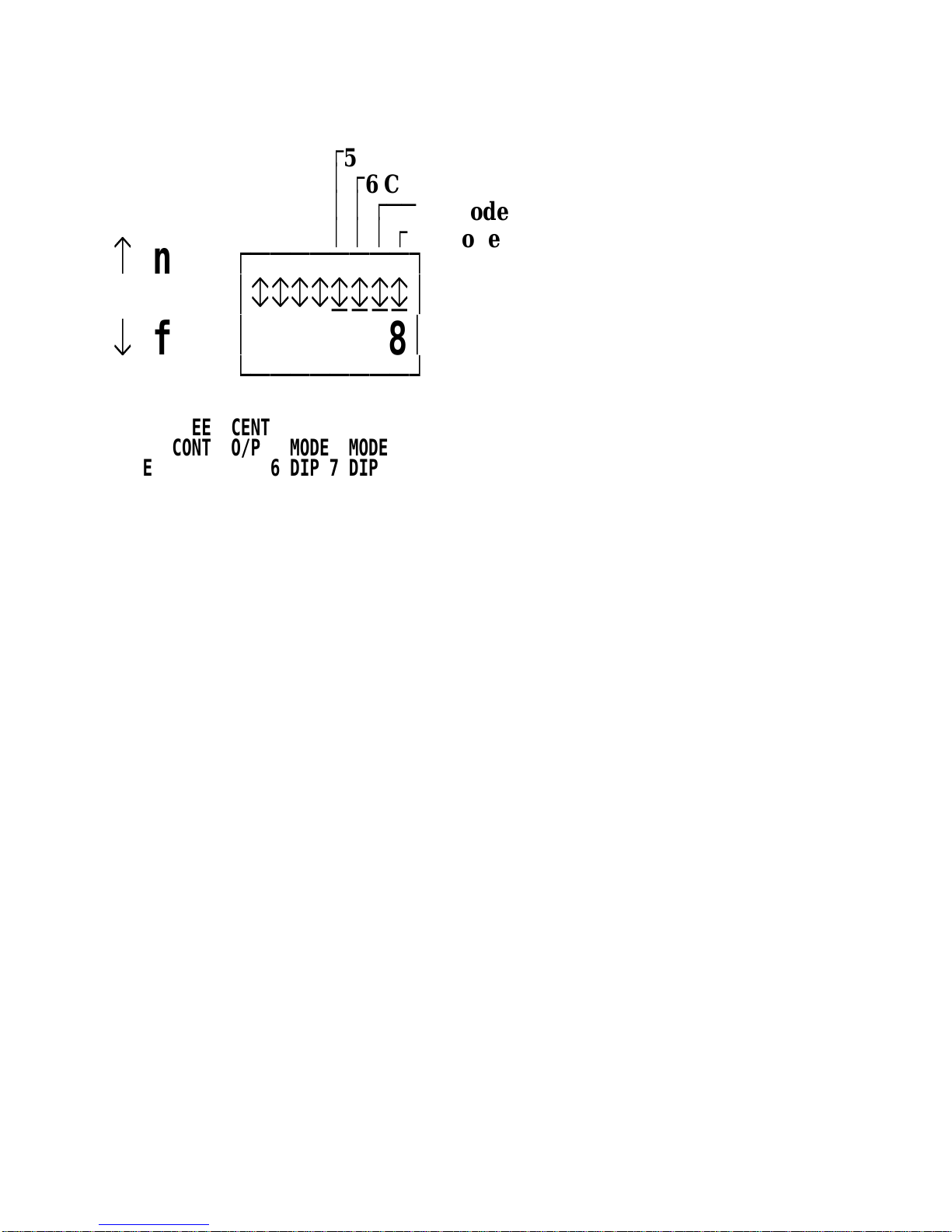
PSI BOX Reference Modes 1-6 & 8.
Figure 6-1 The Mode DIP Switches Settings.______________________________________
Ú
5 IEEE Controller
³ Ú
6 Centronic O/P
³ ³ ÚÄÄ
7 Mode
³ ³ ³ Ú
8 Mode
å
on
ЪДДДДДДДД¿
³ггггдддд³
æ
off
³
12345678
³
АДДДДДДДДЩ
IEEE CENT
CONT O/P MODE MODE
MODE DIP 5 DIP 6 DIP 7 DIP 8 FUNCTIONS SELECTED____ _____ _____ _____ _____ __________________
1 0 0=Off 0 0 IEEE TO RS232 BI-DIRECTIONAL,
IEEE TO CENTRONICS INPUT.
1P0001MODE 1 With Pet To PC Ascii Conversion.
2 0 1=On 0 0 IEEE TO RS232 BI-DIRECTIONAL,
IEEE TO CENTRONICS OUTPUT.
2P0101MODE 2 With Pet To PC Ascii Conversion.
31000CENTRONICS INPUT TO RS232 OUTPUT.
41100RS232 INPUT TO CENTRONICS OUTPUT.
51010CENTRONICS INPUT TO
IEEE OUTPUT.
61101RS232 INPUT TO IEEE OUTPUT.
71111RS232 TO IEEE BI-DIRECTIONAL. ADVANCED
CONTROL LANGUAGE ALLOWS FULL USE OF
INSTRUMENTATION. PSI BOX PLUS+ ONLY
81001Hewlett Packard Plotter Mode.
RS232 INPUT TO IEEE OUTPUT.
IEEE TALK BACK TO RS232 OUTPUT
Invalid DIP combinations, or a standard PSI BOX configured for
Mode 7, which is only found in the PSI BOX PLUS+, cause the
PSI BOX to flash all its LEDs in sequence to indicate an error.
Page 50 Chapter 6
Page 65

Modes 1-6 & 8. PSI BOX Reference
Mode 1._______
Function: An IEEE to RS232 bi-directional and an IEEE
from Centronics input interface.
Also Listen Only IEEE to RS232 interface.
Switchable CBM Pet to PC Ascii conversion.
Use: PSI makes RS232 and parallel equipment function
as devices attached to IEEE controller.
Example: HP or CBM PET IEEE computer to RS232 laser
printer or modem.
IBM PC parallel port data to IEEE computer.
Summary._________
The PSI BOX acts as an IEEE bus device taking its
instructions from an IEEE controller such as a Hewlett-Packard
9825 or Commodore Pet computer, an RS232 device is
connected to the PSI RS232 port or the output from the parallel
printer port of a PC is connected to the parallel input port of the
PSI BOX. The PSI BOX acts like two separate IEEE devices,
one device is an IEEE to RS232 interface the other device is an
IEEE from parallel interface.
Listen Only Operation.____________________
The PSI BOX can also be set to act as a Listen Only
IEEE to RS232 output interface. To select the Listen Only
configuration set the Mode switches to Mode 1 and set the IEEE
address dip switches all upward, ie address 15. Instead of the
PSI BOX becoming IEEE device 15 it will be in Listen Only
mode. Here the a controller instructs one device to talk and
none, one or more devices to listen, the PSI BOX will listen in
to all the data transmitted on the bus irrespective of the IEEE
device that is addressed to listen, and send it to the RS232 port.
In addition, the PSI BOX will happily listen to a Talk
Only device, in a system without a controller, that does not
provide any addressing information.
Chapter 6 Page 51
Page 66

PSI BOX Reference Modes 1-6 & 8.
Addressed Operation.___________________
The address of the RS232 input output port is as set on the
IEEE address DIP switches. The Centronics port address is one
greater than the RS232 address.
Data written to the RS232 address will be buffered and
sent to the RS232 when the RS232 handshake permits. If the
RS232 output buffer is full then the IEEE handshake will freeze,
with NRFD and NDAC held low, waiting for the RS232 device
to become ready to receive the contents of the PSI BOX buffer.
This ensures that no data is lost!
When data is requested from the RS232 port the PSI BOX
sends any data that is in its RS232 input buffer. The last byte
from the buffer is sent with EOI true. This informs the controller
that the buffer is now empty.
If a byte is requested from the PSI BOX and there is
nothing in its buffer to send then a ’talk with nothing to say’
message is sent, this is the 00 byte with EOI true. This method
of flagging an empty buffer prevents a hang-up in the
handshake.
In a similar manner, when data is requested from the
Centronics input port the PSI BOX sends any data from the
buffer. When the PSI BOX sends the last byte in the buffer it
sets EOI true, indicating to the controller that there is no more
to get. If data is requested when the buffer is empty then a talk
with nothing to say message is generated.
Any data SENT to the PSI BOX for output via Centronics
port is lost since in Mode 1 the Centronics port is input only.
In Mode 1 half the PSI BOX ram acts as the Centronics
input buffer, the other half is evenly split between the RS232
input and output buffers.
Pet To PC Ascii Conversion._________________________
From version 4.3 onwards of the PSI BOX, Commodore
Pet to PC Ascii conversion will be performed depending on the
state of mode DIP switch 8. When the switch is UP, ie ON, all
Page 52 Chapter 6
Page 67

Modes 1-6 & 8. PSI BOX Reference
out going data to the RS232 port will be converted from the Pet
character to standard PC Ascii. All input from the RS232 and
Centronics ports will be converted from PC Ascii to Petscii. The
output conversion is generally used to connect standard RS232
Ascii printers to CBM Pet or C64/128 computers.
Unlike all other PSI BOX modes, in Mode 1 the state of
DIP switch 8 IS monitored whilst the PSI BOX is in operation.
This means that the conversion can be switched in and out at
will whilst the PSI BOX is on. Data already in the buffer will
not be changed only the new incoming data will be converted
according to the setting of DIP 8.
Chapter 6 Page 53
Page 68

PSI BOX Reference Modes 1-6 & 8.
Mode 2._______
Function: An IEEE to RS232 bi-directional and an IEEE to
Centronics output interface.
Switchable CBM Pet to Ascii conversion.
Use: PSI makes RS232 and parallel equipment function
as devices attached to IEEE controller.
Example: HP or CBM PET IEEE computer to RS232 laser
printer or modem.
HP or CBM PET IEEE computer to parallel
plotter or laser printer.
Summary._________
The PSI BOX acts as an IEEE bus device taking its
instructions from an IEEE controller such as a Hewlett-Packard
9825 or Commodore Pet computer, an RS232 device is
connected to the PSI RS232 port or a parallel printer or plotter
is connected to the parallel output port of the PSI BOX. The PSI
BOX acts like two separate IEEE devices, one device is an
IEEE to RS232 interface the other device is an IEEE to parallel
interface.
Listen Only Operation.____________________
The PSI BOX can also be set to act as a Listen Only
IEEE to Centronics output interface. To select the Listen Only
configuration set the Mode switches to Mode 2 and set the IEEE
address dip switches all upward ie address 15. Instead of the PSI
BOX becoming IEEE device 15 it will be in Listen Only mode.
Here the a controller instructs one device to talk and none, one
or more devices to listen, the PSI BOX will listen in to all the
data transmitted on the bus irrespective of the IEEE device that
is addressed to listen, and send it to the Centronics port.
In addition, the PSI BOX will happily listen to a Talk
Only device, in a system without a controller, that does not
provide any addressing information.
Page 54 Chapter 6
Page 69

Modes 1-6 & 8. PSI BOX Reference
Addressed Operation.___________________
The address of the RS232 input output port is as set on the
IEEE address DIP switches. The Centronics port address is one
greater than the RS232 address.
The description of the RS232 port is identical to Mode 1.
Any data sent to the Centronics port is buffered in the PSI
BOX. The PSI BOX sends this buffered data when the
Centronics handshake permits. If the Centronics output buffer is
full then the IEEE handshake will freeze, with NRFD and
NDAC held low, waiting for the Centronics device to become
ready to receive the contents of the PSI BOX buffer. This
ensures that no data is lost!
Attempts to data read from the PSI BOX Centronics port
causes the ’talk with nothing to say’ message to be sent, this is
the 00 byte with EOI true, since in Mode 2 the Centronics port
is OUTPUT only. This prevents a hang-up in the handshake.
In Mode 2 half the PSI BOX ram acts as the Centronics
output buffer, the other half is evenly split between the RS232
input and output buffers.
Pet To PC Ascii Conversion._________________________
Commodore Pet to PC Ascii conversion will be performed
depending on the state of mode DIP switch 8. When the switch
is UP, ie ON, all out going data to the RS232 port and the
Centronics port will be converted from the Pet character to
standard PC Ascii. All input via the RS232 port will be
converted from PC Ascii to Petscii. The output conversion is
generally used to connect standard Centronics or RS232 Ascii
printers to CBM Pet or C64/128 computers.
Unlike all other PSI BOX modes, in Mode 2 the state of
DIP switch 8 IS monitored whilst the PSI BOX is in operation.
This means that the conversion can be switched in and out at
will whilst the PSI BOX is on. Data already in the buffer will
not be changed only the new incoming data will be converted
according to the setting of DIP 8.
Chapter 6 Page 55
Page 70

PSI BOX Reference Modes 1-6 & 8.
The Mode 1+2 IEEE Handshake._____________________________
The controlling computer needs to address the PSI BOX as
a listener or a talker, at the end of a data transfer sequence the
PSI BOX should be un-addressed by the unlisten or the untalk
command. When the PSI BOX is a listener, receiving data, it
recognises that EOI is the end of stream terminator. When
addressed to talk the PSI BOX uses EOI to flag the end of its
data stream to the controller.
In modes 1 and 2 the Data transfer to the IEEE port from the
controlling computer is:
PSI BOX listen address, from IEEE controller computer.
Data bytes.. from IEEE controller computer.
Last data byte + EOI from IEEE controller computer.
Unlisten, from IEEE controller computer.
In modes 1 and 2 the Data from the IEEE port to the controlling
computer is:
PSI BOX talk address, from IEEE controller computer.
Data bytes.. from PSI.
Last data byte + EOI from PSI box.
Untalk, from IEEE controller computer.
The Mode 1+2 Secondary Addresses.________________________________
When working in Mode 1 and Mode 2 the IEEE port
recognises several secondary addresses.
The IEEE device number, the IEEE primary address, of the
PSI BOX is as set on the front panel DIP switches. Secondary
addresses are specified in the OPEN statement that is sent from
the CBM PET computer or HP computer. By requesting or
sending data using these special secondary addresses the PSI
Box can communicate its status and other information to the
IEEE controlling computer. The secondary address in use are as
follows:-
Page 56 Chapter 6
Page 71

Modes 1-6 & 8. PSI BOX Reference
S.A. Talk Function. PSI Commanded To Talk By Controller.____ _____________________________________________
0-12 No special function. PSI BOX sends its buffered data.
13 PSI BOX sends one byte indicating buffer contents status.
00 means no data in PSI BOX buffer.
01 means some data in PSI BOX buffer.
14 PSI Box sends the state of the RS232 port pins.
The PSI Box returns one byte which holds the state of the
handshake pins of the RS232 port.
A 0, zero bit means that the line is held true, +12 Volts.
A 1, one bit means that the line is held false, -12 Volts.
DTR is bit 0 decimal value 1 an output from PSI Box.
RTS is bit 1 decimal value 2 an output from PSI Box.
DSR is bit 2 decimal value 4 an input to PSI Box.
CTS is bit 3 decimal value 8 an input to PSI Box.
DCD is bit 4 decimal value 16 an input to PSI Box.
15 PSI Box sends an identification message, memory size and
software revision date eg P.S.I. BOX V4.3 02/05/90 32K.
S.A. Listen Function. PSI Commanded To Listen By Controller.____ ________________________________________________
0-12 No special function. Data is buffered for output to port.
+15
13 PSI BOX flushes the RS232 or Centronics buffer.
PSI BOX accepts one byte of data from the controller.
Bit 0 decimal value 1 set means flush output buffer.
Bit 1 decimal value 2 set means flush input buffer.
14 RS232 only. The PSI BOX accepts one byte which speci-
fies the level of the RS232 port output pins RTS and DTR.
A 0, zero bit causes the line to be held true, +12 Volts.
A 1, one bit causes the line to be held false, -12 Volts.
DTR is bit 0, decimal value 1, an output from PSI BOX.
RTS is bit 1, decimal value 2, an output from PSI BOX.
The state of the Input cannot be set but only read.
Chapter 6 Page 57
Page 72

PSI BOX Reference Modes 1-6 & 8.
Mode 3._______
Function: Centronics input to RS232 output interface.
Use: PSI connects RS232 printers and plotters to the
parallel printer port of any computer.
Example: HP laser printer to IBM PC parallel port.
Summary._________
The PSI BOX acts as a one way data converter reading
information from a computer’s printer port port and passing it
straight through to an RS232 serial printer or plotter. This is a
popular way of connecting the HP Laser Jet printer, via a buffer,
to the parallel port of a PC.
Data is received according to the Centronics input
handshake and output according to the RS232 output handshake.
In this mode no other sort of data transmission is possible. The
IEEE port is disabled and does not respond to any commands or
data.
If the Centronics input buffer of the PSI BOX becomes
full then it will keep the BUSY line high until the RS232 device
accepts data from the PSI BOX.
In Mode 3 the whole of the PSI BOX ram acts as the
Centronics input buffer.
Page 58 Chapter 6
Page 73

Modes 1-6 & 8. PSI BOX Reference
Mode 4._______
Function: RS232 input to Centronics output interface.
Use: PSI connects parallel printers to the RS232 port
of a computer.
Example: Parallel plotter or laser printer running from
COM1 port of a PC.
Enables parallel printer to be 50 feet or more
remote from the host computer.
Summary._________
The PSI BOX acts as a one way data converter reading
RS232 information from a computer’s serial port and passing it
straight through to a parallel printer or plotter. This is often used
as a method of placing parallel printers etc in a remote location
with the data being sent down a twisted pair RS232 line at high
speed.
Data is received according to the RS232 input handshake
and output according to the Centronic output handshake. In this
mode no other sort of data transmission is possible. The IEEE
port is disabled and does not respond to any commands or data.
If the RS232 input buffer of the PSI BOX becomes full
then it will signal unable to receive more RS232 data until the
Centronics device accepts data from the PSI BOX.
In Mode 4 the whole of the PSI BOX ram acts as the
RS232 input buffer.
Chapter 6 Page 59
Page 74

PSI BOX Reference Modes 1-6 & 8.
Mode 5._______
Function: A Centronics input to IEEE output interface.
Use: PSI connects an IEEE output device to the
parallel printer port of a computer.
Example: HP 7475 IEEE plotter from printer port of a PC
running LOTUS 123, AutoCAD etc.
Commodore IEEE printer from PC printer port.
Summary._________
The PSI BOX acts as a one way data converter reading
information from a computer’s printer port and passing it straight
through to an IEEE bus output device.
Data is received according to the Centronics input
handshake and output according to the IEEE output handshake.
In this mode no other sort of data transmission is possible.
Talk Only Operation.___________________
The PSI BOX can also be set to act as a Talk Only IEEE
from Centronics parallel input interface. To select the Listen
Only configuration set the Mode switches to Mode 5 and set the
IEEE address dip switches all upward ie address 15. Instead of
the PSI BOX becoming IEEE device 15 it will be in Talk Only
mode. Here the a controller instructs one or more devices to
listen, the PSI BOX will take data from its Centronics parallel
input buffer and send it to all the listeners on the bus. The
controller should not instruct any device other than the PSI BOX
to Talk.
In addition, the PSI BOX will happily Talk to a Listen
Only device, in a system without a controller, that does not
provide any addressing information.
Page 60 Chapter 6
Page 75

Modes 1-6 & 8. PSI BOX Reference
Addressed Operation.___________________
The PSI BOX acts as the IEEE controller and is the source
of all IEEE commands. It controls the flow of data on the IEEE
bus by addressing and un-addressing devices. Only one IEEE
device can be accessed when in this mode.
The address of the IEEE device that the PSI BOX accesses
is as set on the IEEE address DIP switches. The PSI BOX sends
a LISTEN command to the IEEE bus before each data byte is
sent.
If the Centronics input buffer of the PSI BOX becomes
full then it will hold the BUSY line high until the IEEE device
accepts data from the PSI BOX.
In Mode 5 the whole of the PSI BOX ram acts as the
Centronics input buffer.
Chapter 6 Page 61
Page 76

PSI BOX Reference Modes 1-6 & 8.
Mode 6._______
Function: An RS232 input to IEEE output interface.
Use: PSI connects an IEEE output device to the RS232
port of a computer.
Example: HP IEEE Thinkjet printer from RS232 port of a
PC running LOTUS 123, AutoCAD etc.
Commodore IEEE printer from PC serial port.
Summary._________
The PSI BOX acts as a one way data converter reading
RS232 information from a computer’s serial port and passing it
straight through to an IEEE bus output device.
Data is received according to the RS232 input handshake
and output according to the IEEE output handshake. In this
mode no other sort of data transmission is possible.
Use Mode 8 for IEEE plotter control from a computer’s
RS232 serial port.
Talk Only Operation.___________________
The PSI BOX can also be set to act as a Talk Only
IEEE from RS232 input interface. To select the Listen Only
configuration set the Mode switches to Mode 6 and set the IEEE
address dip switches all upward ie address 15. Instead of the PSI
BOX becoming IEEE device 15 it will be in Talk Only mode.
Here the a controller instructs one or more devices to listen, the
PSI BOX will take data from its RS232 input buffer and send it
to all the listeners on the bus. The controller should not instruct
any device other than the PSI BOX to Talk.
In addition, the PSI BOX will happily Talk to a Listen
Only device, in a system without a controller, that does not
provide any addressing information.
Page 62 Chapter 6
Page 77

Modes 1-6 & 8. PSI BOX Reference
Addressed Operation.___________________
The PSI BOX acts as the IEEE controller and is the source
of all IEEE commands. It controls the flow of data on the IEEE
bus by addressing and un-addressing devices. Only one IEEE
device can be accessed when in this mode.
The address of the IEEE device that the PSI BOX accesses
is as set on the IEEE address DIP switches. The PSI BOX sends
a LISTEN command to the IEEE bus before each data byte is
sent.
If the RS232 input buffer of the PSI BOX becomes full
then it will signal unable to receive more RS232 data until the
IEEE device accepts data from the PSI BOX.
In Mode 6 the whole of the PSI BOX ram acts as the
RS232 input buffer.
Chapter 6 Page 63
Page 78

PSI BOX Reference Modes 1-6 & 8.
Mode 8._______
Function: An RS232 input to IEEE output interface with
IEEE talk back and RS232 flow control.
Use: Driving a IEEE plotter from the serial RS232
port of a computer so that it completely simulates
an RS232 plotter.
Example: HP 7475 IEEE plotter from RS232 port of a PC
running LOTUS 123, AutoCAD etc.
Summary._________
Many plotters understand Hewlett Packard Graphic
Language, HPGL, amongst these are HP’s RS232 7475 and
IEEE 7475 plotter. There are three essential types of operation
that RS232 HPGL plotters perform.
1) Execution of HPGL plotting commands.
2) Reply to HPGL OUTPUT commands.
3) Response to RS232 interface Flow Control commands.
1) Execution Of HPGL Plotting Commands.__ ____________________________________
Most HPGL commands are concerned with positioning and
selecting pens, plotting shapes and specifying line thickness, pen
speeds etc. These HPGL commands are routed from the host
computer directly to the plotter for execution. The PSI BOX
buffer, in conjunction with any buffer in the plotter, are used to
accept as large an amount of data from the computer as quickly
as possible thus freeing up the computer for other processing.
2) Reply To HPGL Output Commands.__ ________________________________
The HPGL specification allows plotters can be asked to
output to the computer various information. This includes the
pens current coordinates, size of the drawing window, error
states, plotter identification information etc. Several of the output
commands are listed below.
Page 64 Chapter 6
Page 79

Modes 1-6 & 8. PSI BOX Reference
Figure 6-2 HPGL Output Commands._________________________________
OA Output Actual.
OC Output Coordinates.
OD Output Digitised Point.
OE Output Error.
OI Output Identity.
OP Output P1 And P2.
OS Output Status.
OW Output Window.
The talk back facility of Mode 8 allows the plotter to
receive all these output commands and reply to them. When the
PSI BOX RS232 input buffer is empty, the PSI BOX polls the
plotter for a response to the computers request after every three
second period of inactivity on the RS232 bus. This mechanism
allows any data waiting in the plotter buffer to be correctly
received by the computer within a short time of it becoming
available.
3) HPGL RS232 Interface Flow Control Commands.__
______________________________________________________
Whilst the plotting and output commands that the two
plotters understand are identical the RS232 plotter also responds
to several FLOW CONTROL commands that are absent from
IEEE plotters. These Flow Control commands regulate the
transfer of information along the RS232 interface between the
computer and the plotter. Thus the computer can clear the
plotters buffer, request the plotter reply with the size of the
plotters, return an error status and set the output mode of data
between the plotter and the computer. IEEE plotters do not
require these functions but software packages driving RS232
plotters may expect the plotter to behave as if it does have them.
Mode 8 of the PSI BOX allows any IEEE plotter to completely
emulate the Flow Control of an RS232 plotter.
The Flow Control commands are three byte commands that all
start with the ESCAPE character, decimal 27 followed by the
decimal point character. The third character identifies the specific
flow control function. Depending on the command, various
Chapter 6 Page 65
Page 80

PSI BOX Reference Modes 1-6 & 8.
parameters may be specified and a response from the PSI BOX
may be expected.
Figure 6-3 HPGL RS232 I/f Flow Control Commands._______________________________________________
ESC.( Turn plotter On.
ESC.Y Turn plotter On.
ESC.) Turn plotter Off.
ESC.Z Turn plotter Off.
ESC.@ Set monitor mode.
ESC.B Output Available Buffer Size.
ESC.E Output Error Status Code.
ESC.H Handshake Mode 1.
ESC.I Handshake Mode 2.
ESC.J Abort Flow Control Command.
ESC.K Abort Plot, Clear Buffer.
ESC.L Output Maximum Buffer Size.
ESC.M Specify Output Mode.
ESC.N Specify Output Mode.
ESC.O Output Buffer Status Code.
ESC.R Initialise Handshake Parameters.
Addressed Operation.___________________
Since Mode 8 requires the plotter to both listen to HPGL
plotting commands and reply to HPGL output command the
plotter must be set for addressed operation. It must not be set for
Listen only use.
The PSI BOX acts as the IEEE controller and is the source
of all IEEE commands. It controls the flow of data on the IEEE
bus by addressing the plotter to talk or listen. Only one IEEE
device, the plotter, can be accessed when in this mode.
The address of the plotter that the PSI BOX accesses is as
set on the IEEE address DIP switches. The PSI BOX sends a
LISTEN command to the plotter before each HPGL command is
sent, when the trailing CR character is detected the PSI BOX
waits ready to address the plotter again.
If no RS232 bus activity has occurred for 3 seconds, and
the PSI BOX RS232 input buffer is empty then the PSI BOX
polls the plotter for any response it may have. The plotter is
Page 66 Chapter 6
Page 81

Modes 1-6 & 8. PSI BOX Reference
addressed to TALK any response is sent back to the host
computer via the RS232 port. At the end of the plotters output
the plotter is commanded to UNTALK. At every 3 second
interval the plotter will be repolled for further responses.
If the PSI BOX receives a Flow Control command then it
immediately responds to it in the appropriate way.
If the RS232 input buffer of the PSI BOX becomes full
then it will signal that it is unable to receive more RS232 data
until the IEEE device accepts data from the PSI BOX.
In Mode 8 the 28,672 bytes of the PSI BOX ram acts as
the RS232 input buffer with 2048 bytes for the RS232 output
buffer.
Chapter 6 Page 67
Page 82

PSI BOX Reference Mode 7 Overview
CHAPTER 7
AN OVERVIEW OF THE
PSI BOX
MODE 7
Introduction.____________
This chapter is an overview of the operation of the PSI
BOX in mode 7, precise details about the syntax and parameters
of the IEEE commands language are to be found in the next
chapter.
As well as a short summary of the Mode 7 this chapter
contains details about the Mode 7 power up messages, the Mode
7 default parameters, data pass through mode, the BUS
command sequence, sending data to IEEE devices, receiving data
from IEEE devices, IEEE control status string, the RESET
command and character, the current device, a summary of the
BUS command language and finally the Mode 7 memory
allocation.
Mode 7 In 15 Minutes!.____________________
A good way of using the PSI BOX in Mode 7 is
interactively from the keyboard of your PC via a terminal
emulation program or a modem program such as one of the
many share ware programs like PC TALK or PROCOM. In this
way the user can get a good feel of the power and ease of use
of the Mode 7 command language in a very short time.
To get up and running within the shortest possible time we
have included two terminal emulation programs with the PSI
BOX PLUS+. These are written in PC BASIC and come
Page 68 Chapter 7
Page 83

Mode 7 Overview PSI BOX Reference
compiled ready to run and also as source code for you to modify
as you wish. Both programs have been complied using
Microsoft’s excellent Quick Basic V4.5 compiler, the source
code is also compatible with other compiler such as Borland’s
Turbo Basic. The two programs are called COMM and PSIBOX.
COMM.EXE____________
The COMM.BAS file is the source code for the compiled
COMM.EXE program. The COMM program is a very simple,
bare bones program, with just the minimum needed code to talk
to the PSI BOX. It opens COM1 to talk to the PSIBOX at 1200
baud, 7 data bits, Even Parity and 1 stop bit. Any key pressed
on the PC, is echoed on the screen and is then sent to the
PSIBOX. Every character received from the PSI BOX is printed
on the PC screen. To change the communications parameters it
is necessary to edit the source code and either recompile or run
the program using the BASIC interpreter.
PSIBOX.EXE_____________
The PSIBOX.BAS file is the source code for the compiled
PSIBOX.EXE program. The PSIBOX program is more sophisticated and has menu driven serial port parameter selection,
predefined Function Keys to access PSI features etc etc. We
encourage you to use the programs and you are free to modify
and incorporate the code into your own programs provided they
are used to drive our products.
Mode 7 Summary.________________
Mode 7 is an RS232 to IEEE bi-directional interface. Data
is sent and received using the RS232 and IEEE handshakes. In
this mode no other sort of data transmission is possible, the
parallel port can not be used as either an input nor as an output.
Typically mode 7 is used to control several IEEE devices or
instruments from the RS232 port of a computer. eg Commodore
Amiga IEEE controller, BBC Master IEEE controller, Acorn
Archimedes IEEE controller, Atari ST IEEE controller or IBM
Chapter 7 Page 69
Page 84

PSI BOX Reference Mode 7 Overview
PS/2 IEEE controller.
The PSI BOX acts as the IEEE controller and is the source
of all IEEE commands. It controls the flow of data on the IEEE
bus by addressing and un addressing devices to talk or listen. Up
to 14 IEEE devices may be accessed when in this mode.
A sophisticated command language is used to control the
IEEE bus via the PSI BOX. It is similar in concept to the
HAYES modem control language, and the commands and syntax
are based on those used in the our Professional 488 Device
Driver for our range IBM PC and PS/2 compatible IEEE
interface. The character sequence that invokes the IEEE
command language is <CR> BUS
Characters sent to the PSI BOX that do not start with the <CR>
BUS sequence are treated as data to be sent direct to the current
IEEE device, the data is thus passed straight through from the
RS232 port to the IEEE bus.
Mode 7 Power Up.________________
The basis of the Mode 7 IEEE handler is an intelligent
command handler. This is a piece of software resident on the
PSI BOX rom. It is called into operation automatically whenever
the PSI BOX is powered up or reset when DIP switches are set
to Mode 7 as shown in the PSI BOX manual page 7 Figure 4.
Once the PSI BOX has been powered on in Mode 7 you
can access the IEEE bus in two ways. By default data sent to
the PSI BOX from the RS232 computer is passed though to the
current IEEE device. Alternatively the data sent to the PSI BOX
is interpreted as a Mode 7 BUS command.
When the PSI BOX is switched on in MODE 7 it sets up
and maintains a list of parameters, the IEEE control status string.
These parameters describe the current IEEE address, secondary
address, state of ATN, SRQ and REN lines, input and output
Page 70 Chapter 7
Page 85

Mode 7 Overview PSI BOX Reference
byte counts, SERIAL POLL and PARALLEL POLL status bytes,
EOS and END bytes etc.
The IEEE control status string is very important, its format
is identical to the PC IEEE control status string. Changing the
parameters in the IEEE status string controls the operation of the
PSI BOX, the source and destination of IEEE data exchanges
and many other vital criteria.
The precise format of the data in the IEEE control status
string is given on the PSI BOX Mode 7 Quick Reference Card
and is given later on in this chapter.
On power up in mode 7 the PSI BOX sends a string of
data to the RS232 computer. This message consists of the
current PSI BOX rom version and the default IEEE control
status string.
PSI BOX Version 4.0f 16/03/90
STATUS 04, ,0,1,1,0,00,00000,00000,000,000,000,0,0,1 etc
The ’my listen’ and the ’my talk’ address of the PSI BOX
are by default zero.
The address of the IEEE current device that the PSI BOX
is to access is that set on the IEEE address DIP switches, and is
the first field in the status string. The current device can be
changed at any time from the RS232 computer using a BUS
command. The default secondary address is NONE, this is stored
as the second field in the status string.
The Default Mode 7 Configuration._______________________________
The default PSI BOX Mode 7 configuration as it powers
up without any changes being made via the BUS command. Is
given below.
Chapter 7 Page 71
Page 86

PSI BOX Reference Mode 7 Overview
Figure 7-1 The Default Mode 7 Configuration.________________________________________
DEFAULT IEEE DEVICE NUMBER =AS SET BY DIP SWITCHES
DEFAULT IEEE SECONDARY ADDRESS =NONE
TIME OUT VALUE =10 (1 second)
PSI BOX MY LISTEN ADDRESS =00
PSI BOX MY SECONDARY ADDRESS =NONE
PSI BOX MY TALK ADDRESS =00
END OF INPUT TERMINATION (EOS=) =EOI ASSERTED BY DEVICE
END OF OUTPUT METHOD (END=13) =EOI SENT WITH <CR>
RS232 PORT ECHO STATE =OFF. ECHO=OFF
EMERGENCY RESET CHARACTER =@. DECIMAL 64
INTERFACE CLEAR LINE IFC =PULSE TRUE>100 micro sec
REMOTE ENABLE LINE REN =ASSERTED TRUE
ATTENTION LINE ATN =ASSERTED TRUE C-A-C
Data Pass Through Mode._______________________
By default any data, that does not start with the BUS
command sequence, is treated as data to passed straight though
the PSI BOX to the current IEEE device.
At the start of the data stream the PSI BOX sends the
current device LISTEN address. Then the current secondary
address, if any. Then the data received from the RS232 host
computer is sent byte by byte. The EOI will be set true
concurrently with a data byte and will be followed by the UNL
command according to the End Of Sequence method specified
by the EOS= command.
Any data that starts with a <Carriage Return> or <Line
Feed> character will be buffered until it has been checked for
the BUS command sequence. Thus the data sequence:<CR> BUFFET
will have the three bytes <CR> BU stored by the PSI BOX until
the F character arrives, as this point the PSI BOX determines
that <CR> BUS has not been received from the host RS232
computer. Therefore the PSI BOX sends <CR>BUF to the
current device on the IEEE bus and the later characters FET are
sent as soon as they have been received.
Page 72 Chapter 7
Page 87

Mode 7 Overview PSI BOX Reference
For unambiguous data output to the IEEE bus devices use
the OUTPUT command.
The BUS Command Sequence.___________________________
All data output from the controlling computer’s RS232 port
is inspected for the following sequence of bytes:<Carriage Return> BUS
Here B is the Ascii character decimal 66.
U is the Ascii character decimal 85.
S is the Ascii character decimal 83.
<Carriage Return> is Ascii character decimal 13.
One or more Carriage Returns and Line Feeds, Ascii
character 10, may be inserted before the BUS
characters.
After receiving the <CR> BUS sequence the data following
up until a trailing <CR> with optional <LF> is treated as an
Ascii string containing IEEE bus keywords and numeric
parameters. These keywords are interpreted as commands to
perform Serial or Parallel Polls, send any IEEE bus commands
or specify the timeout period.
The command interpreter checks the syntax of your IEEE
string and responds with ’All done OK’ or ’Error in command’
as appropriate.
If an error has been detected then all the commands in the
received string prior to the error will have been executed. The
exact place the error occurred is given by the field in the IEEE
control status string positioned at bytes 44-46. The value in this
field is the position of the byte in the previous BUS command
that the PSI BOX did not recognise, the PSI BOX starts
counting from the B in BUS as position 1.
In addition to the PSI BOX responding with the message
’Error In Command’ there is a syntax error flag is the byte at
Chapter 7 Page 73
Page 88

PSI BOX Reference Mode 7 Overview
position 42, it is 1 when there was a syntax error in the previous
string and 0 when no syntax error was detected. This syntax
error flag is of most used for programmed applications whilst the
message ’Error In Command’ is particularly effective during
interactive use.
If any new line of information starts with the characters
BUS, in upper case, then that line is treated as a PSI BOX
command. The PSI BOX processes the command and takes any
necessary action.
If any line of information does not start with BUS then the
PSI BOX treats it as data to be output to the current IEEE
device.
A new line is said to start after a CR or CR+LF character
sequence.
Every BUS command is terminated by a carriage return.
All the parameters in an BUS command are numerals 0-9 or are
any mix of upper or lower case letters, a-z and A-Z, with the
+"= characters. Parameters are separated by spaces or commas.
Extra spaces can be used to separate parameters to make the
commands more readable. These extra spaces are ignored by the
PSI BOX command parser.
The BUS command can contain one or more valid commands in
any sequence desired provided that not more than 128 characters
are sent at any one time. Remember a <CR> must be used to
terminate the string.
BUS SPOLL 6 Listen 5 DATA 65,76,80 EOI 13 UNL <CR>
About 60 IEEE commands are available in MODE 7.
These are listed below. The PSI BOX Mode 7 Quick reference
Card lists the commands and gives the exact BUS command
language syntax. A later chapter in this manual gives command
syntax as well as the IEEE bus activity and data returns that
results from each command.
Page 74 Chapter 7
Page 89

Mode 7 Overview PSI BOX Reference
Sending Data Using The Bus Command.___________________________________
Data can be sent to the IEEE bus devices in several ways.
As mentioned previously data sent in pass through to the current
device. Additionally data can be sent to the IEEE bus devices
using the BUS command.
The data may be sent in one of three ways:- as specified
by decimal numbers after a DATA or EOI command, as literal
data within delimiters after a STRING command, as literal data
within delimiters after an OUTPUT command.
BUS LISTEN 5 DATA 72,69,76,76,79 UNL <CR>
BUS LISTEN 5 STRING "HELLO" UNL <CR>
BUS OUTPUT "HELLO" <CR>
Whilst these methods the main differences lie in the fact
that the addressing of the devices has to be explicitly given
when using the DATA and STRING commands but that the
OUTPUT command addresses the current device by default.
Receiving Data Using The Bus Command.____________________________________
Data can be requested from any IEEE bus device using
either the READ or ENTER command.
BUS TALK 5 READ UNT <CR>
Like the DATA command the READ commands requires
the user to give explicit addresses and unaddresses when
receiving data. The READ command reads one data byte from
the addressed talker, the byte is stored in the IEEE control status
string, position 66-68.
BUS ENTER <CR>
BUS ENTER 200 <CR>
The ENTER command is much more flexible, a complete
bus handshake sequence is performed with the current device
Chapter 7 Page 75
Page 90

PSI BOX Reference Mode 7 Overview
being addressed to talk. The input sequence is terminated by the
receipt of the number of bytes specified or by EOS received.
The maximum number of bytes allowed to be requested using
the ENTER command is 65535 bytes.
The IEEE Control Status String.____________________________
One of the great advantages of the IEEE 488 bus it that up
to 16 devices may be simultaneously present on it, without
confusion as to which one we want to use. Each device has a
unique IEEE address, or device number. Each stream of data that
is transferred on the IEEE bus is preceded by addressing bytes
that inform the bus which device is to transmit data and which
devices are to receive the data. But how do we tell the PSI BOX
which device we want next.
The PSI BOX stores a table of data that it uses to inform
itself of which devices to access and in what manner it should
control the bus. This table of data is called the IEEE control
status string. The IEEE control status string also holds
information on parallel and serial poll responses, time out data,
byte counts of data transferred during the previous i/o and many
other interesting parameters. The first field of the IEEE control
status string holds the current IEEE device number, the second
field is that device’s secondary address.
The PSI BOX status string can be accessed in two formats.
The STATUS command causes the PSI BOX to send the
string as a series of ascii numbers separated by comma’s, it is
about 128 bytes long.
The SHOW command sends the status string back with
explanations. It has each of the fields labeled with text to help
explain its function. The format is ideal for display on an 80
character screen, about 1500 characters are sent. The SHOW
command is intended for interactive debugging by a person, the
STATUS command returns a string that is easier for a program
to handle. The large size of the SHOW response, especially
Page 76 Chapter 7
Page 91

Mode 7 Overview PSI BOX Reference
down a low speed RS232 line makes of best use whilst
programs are being debugged.
BUS SHOW <Carriage Return>
The first few lines of the SHOW response looks like:-
Current Device= 04 Curr Sec Add=NONE Service ReQ = 0 ATtentioN = 0
Remote ENable = 0 Bus Status = 00 Input Count =000 Output Count=00
Serial Poll = 000 Init SP Data= 000 P Poll Data =000 ON SRQ Done = 0
Syntax Error = 0 Error Pos = 000 ECHO Flag = 0
My Listen Add = 00 My Secdy Add=NONE My Talk Add = 00 Debug = 000
Time Out Value= 10 Read Data = 000 RESET Byte = 064 Address = 000
EOS Byte = 013 EOS Bit Mask= 8 END Byte = 013 END Bit Mask= 8
The current PSI BOX status string will be sent from the
PSI BOX to the RS232 host computer whenever the PSI BOX
receives the STATUS command.
BUS STATUS <Carriage Return>
Alternatively, for increased ease of use, a BUS command
without any parameters or keywords will be treated as a
STATUS command. Any spaces after BUS but before the <CR>
are ignored.
BUS <Carriage Return>
A request for the STATUS causes the PSI BOX to return the
IEEE control status string to the RS232 host computer. This is a
string of Ascii characters preceded by the word STATUS and
terminated by a CR character, decimal 13. The string is made up
of a series of numbers separated by commas and looks like:-
STATUS 04, ,0,1,1,0,00,00000,00000,000,000,000,0,0,1 etc
Currently the IEEE control status string is approximately
90 bytes long, as new features are added to the PSI BOX
Chapter 7 Page 77
Page 92

PSI BOX Reference Mode 7 Overview
software the length of the control status string increases. It is
advised that 256 bytes of space are set aside for the IEEE
control status string in your program to allow complete
compatibility with future version of the Mode 7 software. The
format of the data returned is given in below.
Figure 7-2 The IEEE Control Status String.______________________________________
BYTE RANGE FIELD DESCRIPTION.____ _____ __________________
1-2 00-30 Current device IEEE device number
4-5 00-30 Current device IEEE secondary address. SPACE SPACE
means no sa.
7 0 or 1 SRQ input line. 1 means SRQ is asserted true by a
device so requesting service.
9 0 or 1 ATN output line. 1 means that PSI BOX is the active
controller asserting attention.
11 0 or 1 REN output line. 1 means that the PSI BOX is
asserting REN true. Devices under IEEE control.
13-14 00-15 IEEE bus status field. 4 bits each representing a
particular state. Bit0 = time out on o/p, bit1 =
time out on i/p, bit2 = EOI/EOS on i/p, bit3 = no
device present.
16-2 000000-65535 The number of bytes read from bus on last input.
22-26 00000-65535 The number of bytes sent to the bus on last output.
28-30 000-255 The SERIAL POLL data for the current device,
current device address as in bytes 1-2.
32-34 000-255 The SERIAL POLL data for the first device addressed
in the previous SPOLL command.
36-38 000-255 The PARALLEL POLL data from the previous parallel
poll command.
40 0 or 1 ON SRQ flag. 1 means an ON SRQ has been auto-
matically performed since IEEE data was last read.
42 0 or 1 IEEE control data syntax error. 1 means the
previous BUS string written to the PSI BOX
contained an error.
44-46 000-255 Syntax error byte. This is the position of the
first byte in the previous BUS command that the PSI
BOX did not recognise. Starts counting from the B
in BUS as 1.
48 0-9 ECHO flag. 0 is the default ECHO=OFF. 1 is ECHO=ON.
50-51 00-30 MLA. The MY LISTEN ADDRESS of the PSI.
53-54 00-30 MSA. The MY SECONDARY ADDRESS of the PSI. SPACE
SPACE means no MSA.
56-57 00-30 MTA. The MY TALK ADDRESS of the PSI.
59-61 000-255 Debug field .. reserved.
63-64 00-15 The current time out value. 00= wait for ever till
device is ready.
Page 78 Chapter 7
Page 93

Mode 7 Overview PSI BOX Reference
66-68 000-255 READ command returned data field.
70-72 000-255 RESET byte, The PSI BOX does Power On Reset when it
receives this byte.
74-76 000-255 Reserved.
78-80 000-255 EOS byte. PSI BOX recognises that this is the last
byte in a string sent by a talker. 000 when unused.
82 7 or 8 Number of bits to match in EOS byte. 7 or 8 bits.
84-86 000-255 END byte. PSI BOX only sends EOI true when this byte
is sent as last in a stream. When EOS width=7or8
88 0,7 or 8 Number of bits to match in END byte. 7 or 8 bit
bytes. If =0 then never send EOI true when PSI BOX
sending data!
89 Comma
90 Carriage Return, End marker.
91-255 Reserved for future use. Make sure you allow for
these extra bytes.
The RESET Command and Character.__________________________________
Of particular interest is the RESET command and
character. Whenever the PSI BOX receives the reset character
from the RS232 host computer it performs a power on reset.
Everything is returned to the default state and an IEEE bus
ABORT command is performed. An ABORT command pulses
the IFC line for at least 100 micro seconds, then asserts the
REN and ATN lines true.
This reset function is to get you out of trouble if the IEEE
bus devices hang when , say, timeouts are disabled and a device
crashes. The default reset character is @ the Ascii character
decimal 64.
The RESET command can be used to specify which Ascii
character is to be used instead of the default character @, so
allowing for flexible data formats.
The Current Device.__________________
A concept that effects many bus operations is the current
device. The current device is extremely important since all data
sent via the PSI BOX in data pass through and all data received
from bus via the ENTER command is to and from the current
IEEE device. In addition, many of the IEEE controls and
Chapter 7 Page 79
Page 94

PSI BOX Reference Mode 7 Overview
functions access the current device when no device number is
explicitly specified.
The PSI BOX front panel DIP switches allows you to
specify the INITIAL value of the IEEE current device number,
the default secondary address is none.
During operation, the current device, can be set in two
ways. It may be set at any time when an Ascii number is the
first one or two parameters after a BUS command.
To set device 5 no secondary address as the current device
send the following sequence:<CR> BUS 5 <Carriage Return>
To set device 6 with a secondary address of 2 as the current
device send the following sequence:<CR> BUS 6, 2 <Carriage Return>
The first two fields of IEEE control status string will be updated
to reflect the information send.
Secondly, PSI BOX allows the current device number to
be changed using the TALK, TAD, LAG, LISTEN and other
addressed IEEE functions. With this method the current device is
automatically set to the last device address specified.
<CR> BUS LISTEN 2 <Carriage Return>
Changes the current device to 2
<CR> BUS LISTEN 2+3 <Carriage Return>
Changes the current device to device 2 secondary address 3.
<CR> BUS TALK 2 LISTEN 3,4
Changes the current device to device 4.
<CR> REMOTE 2,3,4 <Carriage Return>
Changes the current device to device 4.
Page 80 Chapter 7
Page 95

Mode 7 Overview PSI BOX Reference
<CR> BUS SPOLL 3,4,5 <Carriage Return>
Changes the current device to device 4.
The golden rule is that the last device specified is now the
current device.
Mode 7 BUS Command Summary.______________________________
Figure 7-3 Mode 7 IEEE Command Primitives________________________________________
DCL Device Clear. GET Group Execute Trigger
GTL Go To Local. LAG Listen Address.
LLO Local Lockout. MLA My Listen Address.
MTA My Talk Address. PPC Parallel Poll Configure.
PPD Parallel Poll Disable. PPE Parallel Poll Enable.
PPU Parall Poll Unconfigure SDC Select Device Clear.
SPE Serial Poll Enable. SPD Serial Poll Disable.
TAD Talk Address. TCT Take Control.
UNL Unlisten. UNT Untalk.
CMD Send byte ATN true. DATA Send byte ATN false.
EOI Send DATA with EOI true LISTEN Listen Address.
SEC Secondary Address. TALK Talk Address.
Figure 7-4 Mode 7 IEEE Line Controls.__________________________________
ATN Asserts ATN when not sending data.
IFC Pulse the IFC line true for 100 micro-sec
NO ATN Leaves ATN false when not sending.
NO REN Leaves REN false.
REN Asserts REN line continuously true.
Chapter 7 Page 81
Page 96

PSI BOX Reference Mode 7 Overview
Figure 7-5 Mode 7 IEEE Command Functions.________________________________________
ABORT Resets the bus ,pulse IFC, assert REN, assert ATN.
CLEAR Resets ALL devices. Performs DCL, device clear.
CLEAR 6,7 Resets devices 6 and 7. Performs SDC.
CONFIGURE Configures device’s response to PPOLL.
DISABLE Prevents some or all devices responding to PPOLL.
ECHO= Instructs PSI BOX to echo RS232 data back to host.
END= Sets the End of Sequence method for OUTPUTs from PSI.
ENTER Ask for data from IEEE device.
EOS= Specifies EOS string for IEEE data INPUTs to PSI BOX.
LOCAL Enable front panel control. REN and ATN sent false.
LOCKOUT Disable front panel controls. Performs LLO command.
MACRO Defines or lists a user’s own macro command.
MESSAGES= Enable or disable PSI BOX to host error messages.
NO TO Disables time out.
OUTPUT Sends data to current bus device.
PPOLL Performs a complete Parallel Poll
READ Reads one byte of data from addressed talker.
REMOTE Asserts REN line continuously true, sets ATN false.
SHOW Display & Explain Control Status String.
SPOLL Serial Polls the current device.
SPOLL 6,7 Serial Polls devices 6 and 7.
STATUS Sends the current PSI BOX parameter table to RS232.
TIMER Wait for a given number of milli seconds
TO Sets an i/o timeout value.
TRIGGER Performs Group Execute Trigger.
UNCONFIGURE Prevents devices responding to Parallel Poll.
VERSION Returns the ROM version number and date.
WAIT Wait for a given number of milli seconds
WAIT SRQ Waits till SRQ is asserted by device.
X Execute stored macro a specified number of times.
@ Emergency RESET.
RESET Specify the RESET character.
Mode 7 Memory Allocation.________________________
The built in 32K buffer of the PSI BOX can be bypassed
by setting the BUFFER ON front panel DIP switch low when
the PSI BOX is powered on or reset.
Regardless of whether the buffer is enabled the PSI BOX
allocates approximately 256 bytes of ram to hold the Mode 7
IEEE control status parameter table. In addition, another 256
bytes are always set aside for the RS232 input buffer, this
allows the PSI BOX to a compile a complete BUS command in
Page 82 Chapter 7
Page 97

Mode 7 Overview PSI BOX Reference
its memory, as it waits for the trailing <CR> before the
command is interpreted.
When the buffer is enabled then one half of the PSI BOX
ram, 16K, acts as the RS232 input buffer, the other half as the
RS232 output buffer.
If the RS232 input buffer of the PSI BOX becomes full
then it will be unable to receive more RS232 data until the IEEE
device accepts data from the PSI BOX.
If the RS232 output buffer of the PSI BOX becomes full
then the PSI BOX will be unable to receive any more IEEE data
until the RS232 device accepts data from the PSI BOX.
The transfer of data between the PSI BOX and the
computer’s RS232 port is governed by either the XON/XOFF
handshake or by the DTR/DSR etc lines, as selected by the user
via the XON XOFF front panel DIP switch.
Chapter 7 Page 83
Page 98

PSI BOX PLUS+ Reference Control Functions
CHAPTER 8
THE IEEE BUS
COMMAND
LANGUAGE
CONTROLS &
FUNCTIONS
Introduction.____________
This chapter describes the PSI BOX Mode 7 command
language. First there is a discusion of the types of parameter that
the various commands require. Then there follows complete
alphabetical list of all the Mode 7 commands giving a precise
description of the command syntax, function and usage.
Valid Parameters.________________
With the Mode 7 language covering such a wide range of
functions a variety of parameters is required for the different
IEEE command keywords. Some IEEE commands require no
parameters, some commands require exactly one parameter,
others may optionally have none, one, two or more parameters.
The separator between commands and successive
parameters is either a space or a comma. The parameters fall
into the following types, note the address list <add list> is of
particular interest.
<none> No parameters are required. Some commands never
have any parameters such as ABORT. Others such as
CLEAR or SPOLL perform differently with and
Page 84 Chapter 8
Page 99

Control Functions PSI BOX PLUS+ Reference
without parameters.
ABORT Terminate bus activity.
CLEAR Reset all devices.
SPOLL Serially Poll current device.
<add> A valid primary IEEE address. Thus it is in the range
00 - 30 and 128-158. Often devices only require a
primary address.
CLEAR 2 Reset IEEE device 2.
<sa> A valid secondary address. Thus it is in the range 00-
30 and 128-158.
SEC 4 Send secondary address 4 to listener.
<add+sa> A valid primary address with a valid secondary
address.
CLEAR 2+4 Reset IEEE device 2 with sa of 4.
<add list> A list of none, one or more primary addresses with
optional secondary addresses. Here are several
examples of valid address lists. The action that is
taken, eg Serial Poll, is performed on the devices in
the order that they are listed.
CLEAR
CLEAR 2
CLEAR 2+4,6,3
SPOLL 2,4,1,0,7,8
LISTEN 4,3+2,9
Please note that whenever an address list is used,
then <none>, <add>, <add+sa> are all valid
parameters. The address list is a powerful and handy
feature!
<bits> A single digit, either 7 or 8, that defines the number
of significant bits to match in the EOS and END
commands.
EOS=13,7 Input stops on Carriage Return received, 7
bit compare. ie 13 or 141 valid match.
Chapter 8 Page 85
Page 100

PSI BOX PLUS+ Reference Control Functions
EOS=13,8 Input stops on Carriage Return received, 8
bit compare. ie 13 is only valid match.
<byte> A decimal number in the range 0-255. Used mainly
in a data or a command byte.
DATA 13 Carriage return char sent to IEEE bus.
EOI 10 Line feed with EOI true sent to bus.
CMD 63 The UNLISTEN command sent to bus.
<bytes> One or more decimal numbers in the range 0-255.
DATA 79,75,13 OK Carriage return sent to bus.
CMD 63,33,4 The UNLISTEN, LISTEN 1 and
SDC commands are sent to bus.
<number> Decimal number in the range 00000-65535. Used to
specify how many bytes of data to be read using the
ENTER command.
<sppp> Parallel Poll data. The range is 00-15 and is used to
specify how and on which data line the device
responds to the Parallel Poll command, POLL.
CONFIGURE 4+7 Tell device 4 to use data line 8 to
reply to POLL’s. 7=sppp here.
<string> A series of ascii characters, used inside quotation
marks or other delimiters, to specify the literal data
bytes to send. Valid delimiter is any non space
character.
OUTPUT !HELLO! here the string HELLO is sent to
the current device.
<tt> Specify timeout period, range is 0-15. 0 means never
timeout, 1 is 1 millisec, 15 is 50 sec wait
TO 7 Timeout of 1 second.
Page 86 Chapter 8
 Loading...