

Page 1

Print Date: 25.06.2013
Brainboxes Ethernet to Serial
ES - Range Product Manual
Brainboxes Limited, 18 Hurricane Drive, Liverpool International Business Park, Speke, Liverpool, Merseyside, L24 8RL
Tel: +44 (0)151 220 2500 Fax: +44 (0)151 252 0446 Web: www.Brainboxes.com Email: [email protected]
Page 2

Contents
1. Introduction ............................................................................................................................................ 5
2. Before You Start ..................................................................................................................................... 6
Box Contents Check list – ES-357/ES-020/ES-031/ES-042 .................................................................. 6
Box Contents Check list – ES-246/ES-257/ES-313/ES-320 .................................................................. 6
Box Contents Check list – ES-279/ES-346/ES-701/ES-842 .................................................................. 6
Requirements ......................................................................................................................................... 7
System Requirements...................................................................................................................... 7
Network Requirements .................................................................................................................... 7
Supported Operating Systems ............................................................................................................... 7
3. Hardware Features ................................................................................................................................ 8
ES Hardware – 1 & 2 Port Devices ........................................................................................................ 8
ES Hardware – 4 & 8 Port Devices ........................................................................................................ 8
Network IP Addressing ........................................................................................................................... 9
Default Settings ...................................................................................................................................... 9
4. Installation procedures ......................................................................................................................... 10
Connecting Your ES Device ................................................................................................................. 10
Windows Installation: Boost.LAN Manager Application (shown in Windows 7) ................................... 11
Windows Installation: Device Driver (shown in Windows 7) ................................................................. 12
Windows Installation: Boost.LAN Manager Application (shown in Windows 8) ................................... 14
Windows Installation: Device Driver (shown in Windows 8) ................................................................. 17
5. RS-232 Settings (ES-246/ES-257/ES-701/ES-279/ES-357/ES-020) .................................................. 18
The RS-232 Standard ........................................................................................................................... 18
9 Pin D Serial Port RS-232 Cables....................................................................................................... 18
9 Pin D serial port connections to another PC ..................................................................................... 18
6. RS-422/485 Settings (ES-320/ES-313/ES-346/ES-842/ES-357/ES-031/ES-042) .............................. 20
The RS-422 Standard ........................................................................................................................... 20
RS-422 Operation ................................................................................................................................. 20
RS-422 Full Duplex Mode .................................................................................................................... 20
RS-485 Standard .................................................................................................................................. 21
RS-485 Operation ................................................................................................................................. 21
RS-422 Serial Port Cables ................................................................................................................... 23
RS-485 Serial Port Cables ................................................................................................................... 23
ES Range Product Manual
© Copyright Brainboxes Limited 2013
Version 2.9
Page 2 of 66
Page 3

Optional Grounding Arrangements ....................................................................................................... 24
RS-485 Line Failsafe Biasing ............................................................................................................... 24
RS-485 Line Termination ...................................................................................................................... 24
RS-485 Full Duplex (ES-357) ............................................................................................................... 25
RS-485 Half Duplex Autogating Mode (ES-357 Only).......................................................................... 26
RS-485 Half Duplex Mode (ES-313, ES-320, ES-346 & ES-842 only) ................................................ 27
7. Finding your Brainboxes COM port ...................................................................................................... 29
Using the ES-device with your Equipment ............................................................................................... 30
If you are using a COM port based application .................................................................................... 30
If you are using a socket based application ......................................................................................... 30
8. Testing the ES device .......................................................................................................................... 31
9. Advanced Configuration ....................................................................................................................... 32
IP Addressing ....................................................................................................................................... 32
Port Settings ......................................................................................................................................... 33
Changing your COM label .................................................................................................................... 34
Advanced Settings – TCP/IP Settings .................................................................................................. 35
Alternate Access Methods .................................................................................................................... 36
Proxy Server Settings ........................................................................................................................... 36
Device Swapping .................................................................................................................................. 36
Remote Access .................................................................................................................................... 37
Adding a remote device using Boost.LAN Manager............................................................................. 37
Serial Tunnelling ................................................................................................................................... 38
Firewall Exceptions and Port Numbers ................................................................................................ 40
UPnP on/off .......................................................................................................................................... 40
Transmission Interval ........................................................................................................................... 41
10. Web Page Interface ........................................................................................................................... 42
11. Security .............................................................................................................................................. 44
Administrator Access Settings .............................................................................................................. 44
User Access Settings ........................................................................................................................... 44
MAC Address restriction ....................................................................................................................... 45
Restricting “Reset/Restore Default” ...................................................................................................... 46
Authentication Method .......................................................................................................................... 46
12. Exporting & Importing Device Settings .............................................................................................. 47
Exporting Device Settings .................................................................................................................... 47
ES Range Product Manual
© Copyright Brainboxes Limited 2013
Version 2.9
Page 3 of 66
Page 4

Importing Device Settings ..................................................................................................................... 48
13. Rebooting Device ............................................................................................................................... 50
Rebooting in Boost.LAN Manager ........................................................................................................ 50
Manual Reboot ..................................................................................................................................... 50
14. Restoring to Factory Default .............................................................................................................. 51
Restoring back to Factory Default Settings .......................................................................................... 51
Manual Hard Restore ........................................................................................................................... 51
15. Firmware Upgrade ............................................................................................................................. 52
16. Uninstallation ...................................................................................................................................... 54
Complete Boost.LAN Suite Uninstallation. ........................................................................................... 54
Individual Device Uninstallation ............................................................................................................ 54
17. Troubleshooting and Testing ............................................................................................................. 55
18. Linux support for ES devices ............................................................................................................. 58
Configuring the ES device from Linux .................................................................................................. 58
Using Cyclades Serial Client to communicate with ES device ports .................................................... 58
19. Lifetime Warranty and Support .......................................................................................................... 60
20. Technical Specifications..................................................................................................................... 61
Device specification .............................................................................................................................. 61
Network connection ....................................................................................................................... 61
RS-232 Serial Port ......................................................................................................................... 61
RS-422/485 Serial Port .................................................................................................................. 61
Power ............................................................................................................................................. 61
LED indicators ................................................................................................................................ 62
Physical .......................................................................................................................................... 62
Terminal Block Connector Pin out (dependent on ES Model) .............................................................. 63
Storage and Operating Environment Guidelines .................................................................................. 63
21. Regulatory Approvals / Compliance ................................................................................................... 64
Company Accreditation ........................................................................................................................ 64
Europe – EU Declaration of Conformity ............................................................................................... 64
WEEE Directive (Waste Electrical and Electronic Equipment) ............................................................ 64
RoHS Compliance ................................................................................................................................ 65
22. Copyright ............................................................................................................................................ 66
23. Version History ................................................................................................................................... 66
ES Range Product Manual
Version 2.9
© Copyright Brainboxes Limited 2013
Page 4 of 66
Page 5
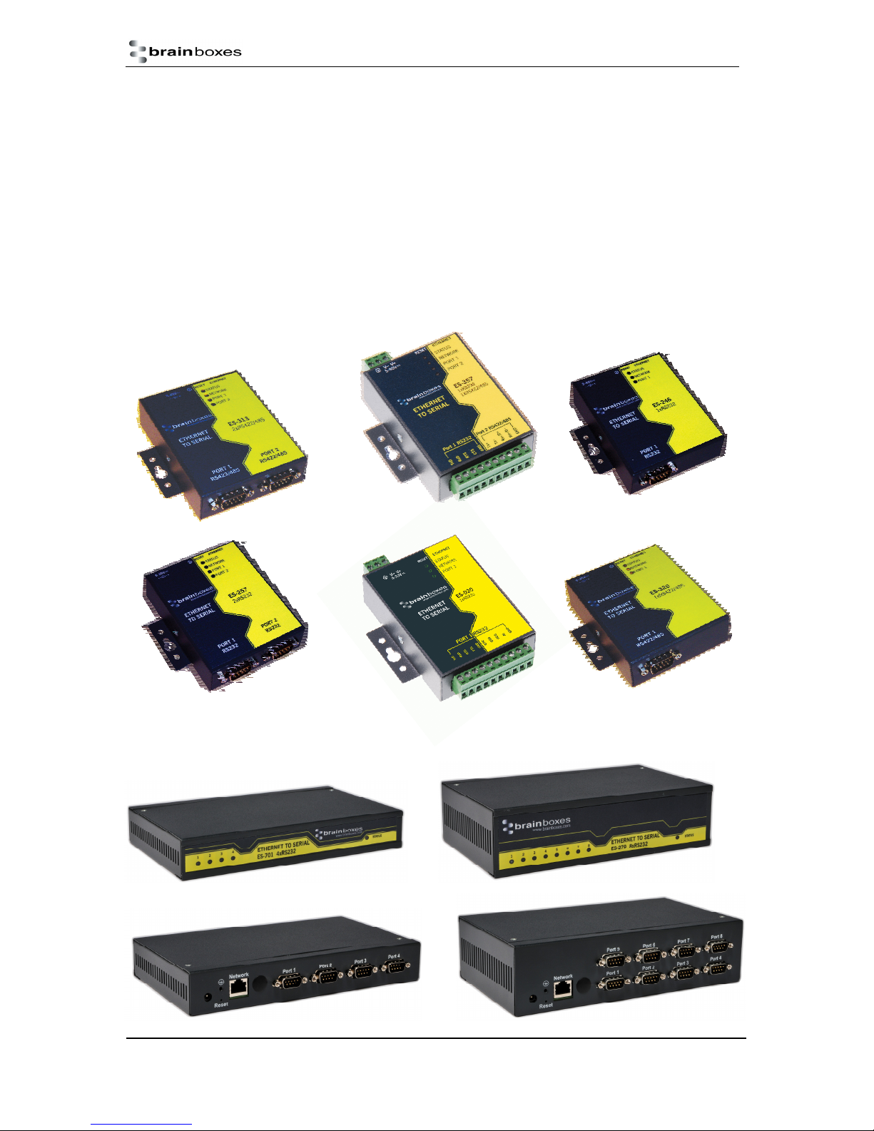
1. Introduction
The Brainboxes ES product range brings the benefits of fast data access and remote management to
asynchronous serial devices by connecting them to the existing local network infrastructure within
your organisation. Designed and built on-site with close collaboration between the hardware and
software teams to deliver a product that is both user-friendly and has plenty of functionality.
The ES product range offers serial devices with support for the RS-232, RS-422 (Full Duplex) and
RS-485 (Full & Half Duplex) serial port standards as well as network communication over raw TCP
and Telnet. The supplied Windows drivers allow you to use any existing software that uses COM
ports, without modification.
ES Range Product Manual
© Copyright Brainboxes Limited 2013
Version 2.9
Page 5 of 66
Page 6

2. Before You Start
Box Contents Check list – ES-357/ES-020/ES-031/ES-042
The following items are included with your product:
Ethernet to Serial (ES) device
Boost.LAN Product CD
Quick Start Guide
Optional Items:
Power supply unit - PW-600
DIN-Rail Mounting Kit (MK-048)
Box Contents Check list – ES-246/ES-257/ES-313/ES-320
The following items are included with your product:
Ethernet to Serial (ES) device
Boost.LAN Product CD
Quick Start Guide
Power Supply (PW-800 - Power Input 5-30V DC 1.8W Max / 1.0W Typical)
o ES-246 – PW-800
o ES-257 – PW-800
o ES-320 – PW-800
o ES-313 – PW-800
Optional Items:
DIN-Rail Mounting Kit (MK-048)
Box Contents Check list – ES-279/ES-346/ES-701/ES-842
The following items are included with your product:
Ethernet to Serial (ES) device
Boost.LAN Product CD
Quick Start Guide
Power Supply (PW-800 - Power Input 5-30V DC 1.8W Max / 1.0W Typical)
o ES-279 – PW-800
o ES-346 – PW-500
o ES-701 – PW-800
o ES-842 – PW-500
Optional Items:
DIN-Rail Mounting Kit (MK070)
Wall Mounting Kit (MK-059)
If any of the items are missing from your box or damaged in anyway please contact
ES Range Product Manual
© Copyright Brainboxes Limited 2013
Version 2.9
Page 6 of 66
Page 7
Requirements
System Requirements
Components: Microsoft .NET Framework 2.0 (installed automatically with Boost.LAN package)
Windows Installer: Windows Installer 3.1 or later (Recommended)
Internet Explorer: If you are running Internet Explorer, then Internet Explorer 6.0 or later is required
Processor: 400 MHz Pentium processor or equivalent (Minimum); 1GHz Pentium processor or
equivalent (Recommended)
RAM: 96 MB (Minimum); 256 MB (Recommended)
Hard Disk: Up to 500 MB of available space may be required
CD or DVD Drive: Not required
Display: 800 x 600, 256 colours (Minimum); 1024 x 768 high colours, 32-bit (Recommended)
Network Requirements
Ethernet network connection (wired).
Supported Operating Systems
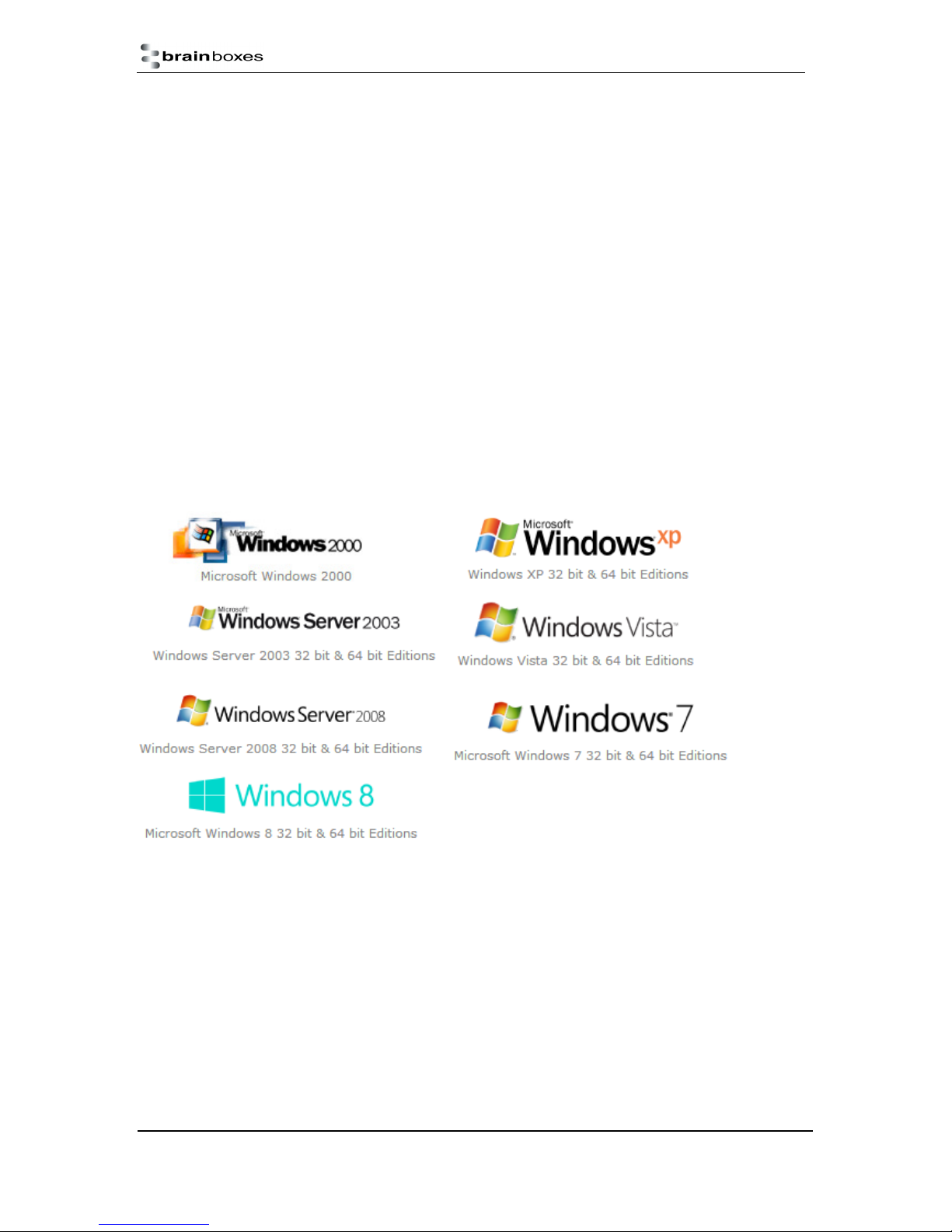
The ES Ethernet to Serial product range can be used in the following Microsoft Operating Systems
with the supplied Boost.LAN drivers:
Brainboxes Boost.LAN drivers have undergone Microsoft testing with the ES range. Upon passing
these tests, the drivers were signed by Microsoft, as an indication of their quality and stability.
It is also possible to use the ES device with a Linux system. See Section 18 for full details.
ES Range Product Manual
Version 2.9
© Copyright Brainboxes Limited 2013
Page 7 of 66
Page 8
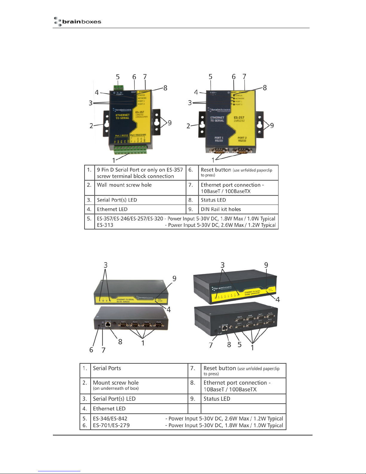
3. Hardware Features
ES Hardware – 1 & 2 Port Devices
ES Hardware – 4 & 8 Port Devices
ES Range Product Manual
© Copyright Brainboxes Limited 2013
Version 2.9
Page 8 of 66
Page 9
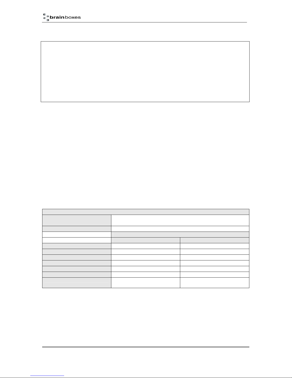
Network Setting
Device Networ
k Address
Web Server Port
Port Settings
RS-
232 Port RS-422
/485 Port
Baudrate
Databits
Stop bits
Parity
Flow Control
Duplex mode
Protocol Settings
For information on power supplies and pin outs please see Section 20 Technical Specifications.
LED Information
Status LED Green Light On
Flashing Green
Flashing Red & Yellow Changing Settings
Flashing between Green & Red Querying IP
Flashing between Green & Red IP Problem
Flashing Green/Red Performing Hard Reset
Flashing between Green & Yellow Problem during initialization (e.g.
Serial Port LED Green light on Port Open
Flashing light on Data RX/TX
Ethernet LED Green light on Link established
Flashing Green Data RX / TX
Device Ready
Firmware Problem)
Network IP Addressing
The ES device is shipped in DHCP Mode.
On connecting to the network, the device automatically checks if it is connected to a DHCP
Server. If this is the case, the DHCP server will allocate an IP address automatically to the ES
device.
If no DHCP Server is detected (e.g. you have the ES device plugged directly into the PC), the
ES device will default to an IP address of 192.168.127.254 within 60 seconds. Please ensure
the PC you’re using for configuration can communicate with the 192.168.127.xxx IP range by
setting the Ethernet port the ES device is plugged into, to an IP address in the same subnet.
If you are using the default IP address with no DHCP server, you can change to a static IP
address to avoid having to wait 60 seconds for the default address of 192.168.127.254
Default Settings
DHCP Mode
80
115200 115200
8 8
N N
1 1
None None
Full Duplex Full Duplex
Telnet + COM port control
Mode (Server)
Telnet + COM port control Mode
(Server)
ES Range Product Manual
© Copyright Brainboxes Limited 2013
Version 2.9
Page 9 of 66
Page 10

4. Installation steps
PLEASE READ CAREFULLY
The “Setup” program will install the Boost.LAN Manager application.
Boost.LAN Manager application is the graphical user interface for locating and configuring all
Brainboxes’ Ethernet to Serial devices in Windows.
Boost.LAN is the COM ports device driver that you will use in Windows to access your ES
ports as standard Windows COM ports. You need Boost.LAN Manager to install the
Boost.LAN COM ports driver.
Neither Boost.LAN Manager or Boost.LAN is required if:
1. Your application speaks directly to IP addresses. (E.g. using telnet or Win sock
communication)
2. You want to remotely change the settings of the ES device via web page access
Follow the instructions below to start the installation process.
If you have any issues with installation, see Section 17
Connecting Your ES Device
1. Connect the ES device to your local network by using an Ethernet cable and plugging into the
Ethernet port connection. The ES Ethernet port will automatically detect the polarity of the
Ethernet connection so both a straight through or crossover Ethernet cable can be used.
2. Connect the power adapter or a DC power line (5-30V) to the ES power terminal block or jack
connection.
If using the Brainboxes PW-644 power supply ensures:
a. the wire marked “-“ is connected to Vb. the wire marked “+” is connected to V+
3. Confirm the device beeps as it is turned on.
4. When the Status LED starts shows a solid green light the device is ready to use.
5. Connect the serial cable from your serial device to the port terminal block or DB 9 connector
(depending on ES model) on the ES device. See Section 20 for pin outs.
Make a note of device MAC address (on the side of the ES device, XX-XX-XX-XX-XX) as you will
need it to identify the device on your network later.
ES Range Product Manual
© Copyright Brainboxes Limited 2013
Version 2.9
Page 10 of 66
Page 11
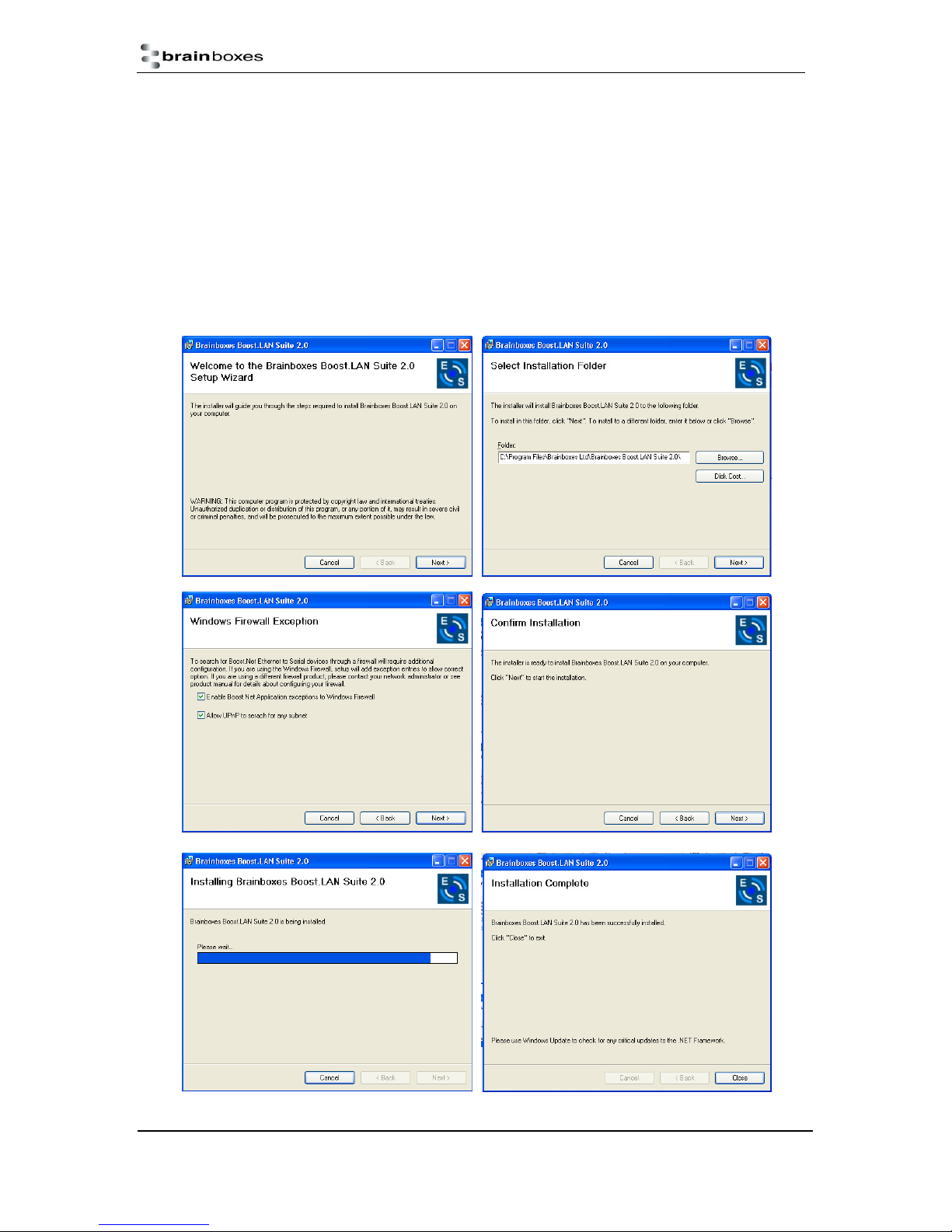
Windows Installation: Boost.LAN Manager Application (Windows 7)
1. With the computer turned on, insert the Boost.LAN Driver CD. This should launch the
Brainboxes Navigation Page
Note: If the navigation page does not auto load, go to Start My Computer Right Click the
CD and select Explore. This will open the CD in Windows Explorer for browsing the contents
of the CD. Locate the “Setup” program on the CD and double click to launch. Proceed to Step
3.
2. Click “Install” to launch the Boost.LAN Setup.exe program.
3. Follow the on screen instructions to install the Boost.LAN Manager application
ES Range Product Manual
© Copyright Brainboxes Limited 2013
Version 2.9
Page 11 of 66
Page 12
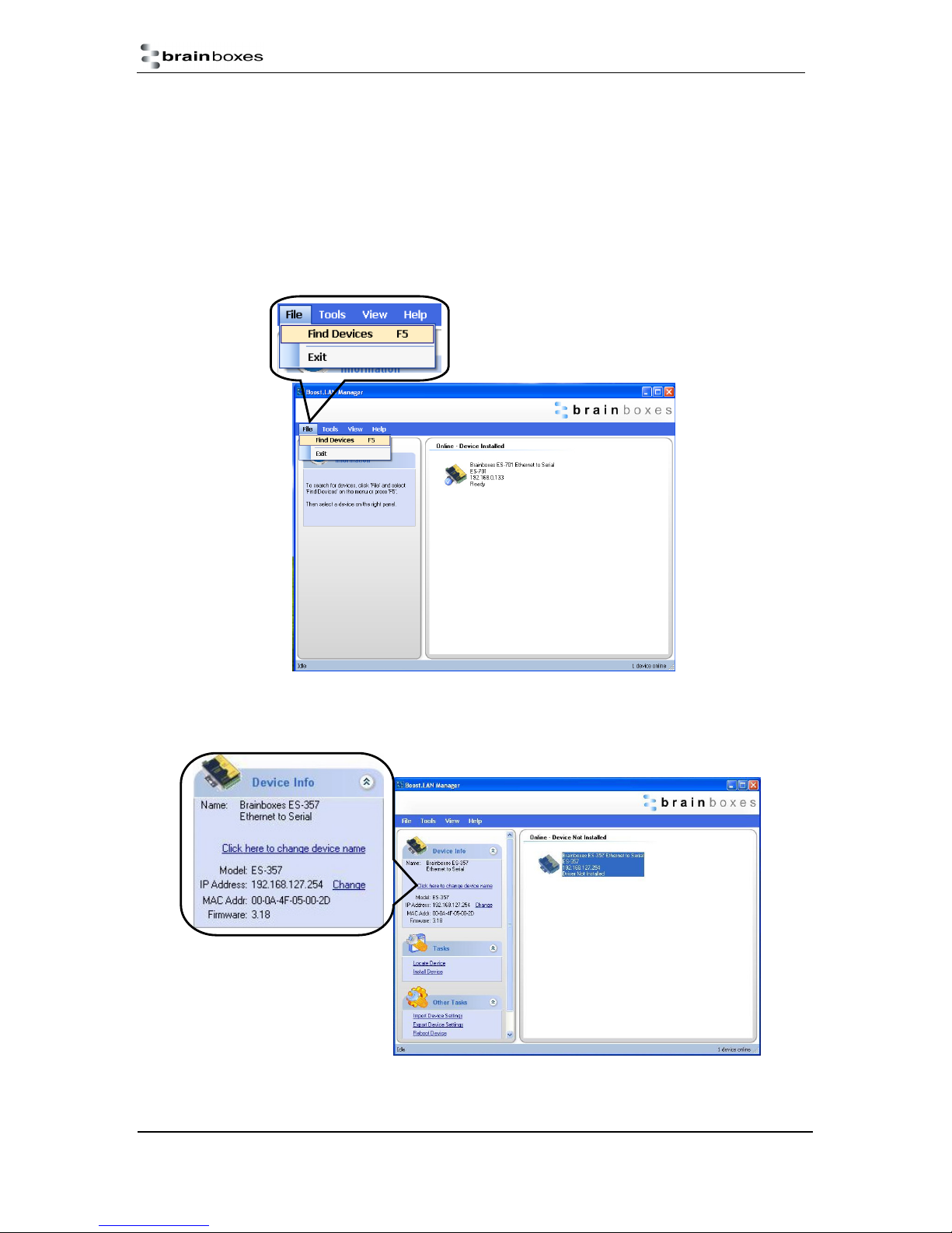
4. When installation is complete, you should see an icon labelled “Boost.LAN Manager” on the
desktop.
Windows Installation: Device Driver (Windows 7)
1. Double click the icon labelled “Boost.LAN Manager” on the desktop to open the
application.
2. Click on the “File > Find Devices” in the top left hand side of the window. This will find any
Brainboxes Ethernet to Serial devices connected to your network.
3. You can find your Brainboxes ES-device by selecting a device and matching it with the
corresponding MAC address available in the left hand panel (see below). The MAC
address of your device is located on a sticker on the side of the ES device.
.
4. Once found, select the device and scroll to the “Tasks” section on the left hand panel.
ES Range Product Manual
© Copyright Brainboxes Limited 2013
Version 2.9
Page 12 of 66
Page 13
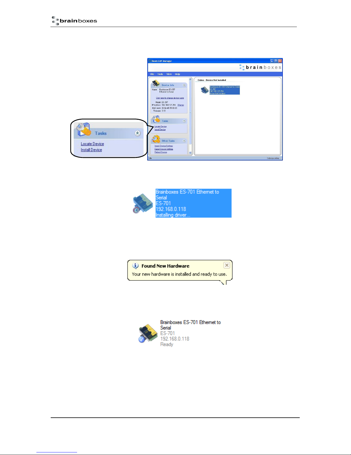
5. Click “Install Device”.
6. During the device installation you will see a timer symbol and the status of the device will
be ‘Installing driver…’.
7. Once the device is installed a pop up box will appear saying ‘Your new hardware is
installed and ready to use.’
8. In Boost.LAN Manger, the device will display a blue tick symbol showing that it is installed
and the status of the device will be ‘Ready’.
9. You can check the COM Number of the Port, by following the instructions in Section 7
Finding your Brainboxes COM port If you need to change the COM port number, see
Section 9 Changing Your COM Label)
ES Range Product Manual
© Copyright Brainboxes Limited 2013
Version 2.9
Page 13 of 66
Page 14
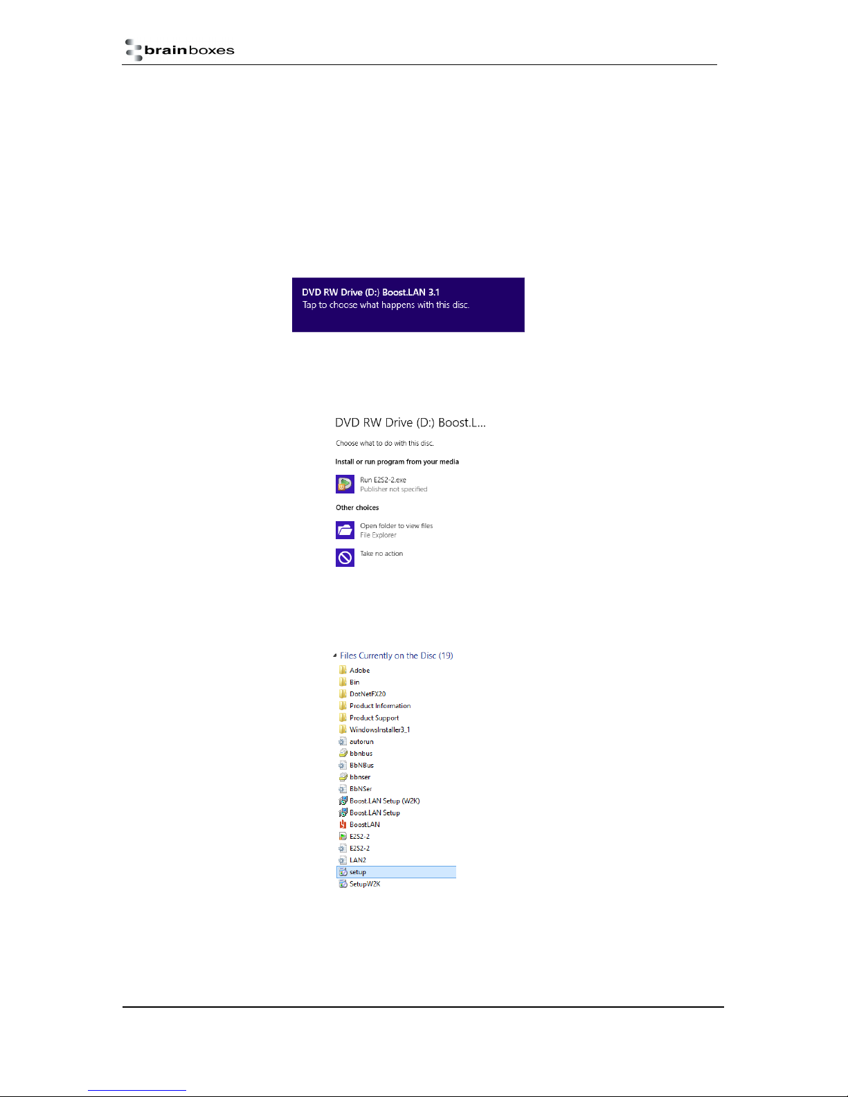
Windows Installation: Boost.LAN Manager Application (Windows 8)
With the computer turned on, insert the Boost.LAN Driver CD.
Note: If the navigation page does not auto load, go to Start My Computer Right Click the CD and
select Explore. This will open the CD in Windows Explorer for browsing the contents of the CD.
Locate the “Setup” program on the CD and double click to launch. Proceed to Step 3.
1. You will now see a purple pop up window as shown below. Click on it.
2. This will bring up a new menu. Select the ‘Open folder to view files’ option.
3. Click on the setup.exe file to begin the installation on the Boost.LAN manager application.
ES Range Product Manual
© Copyright Brainboxes Limited 2013
Version 2.9
Page 14 of 66
Page 15
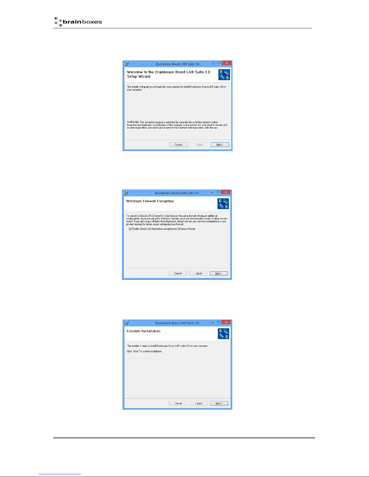
4. When you click on the setup.exe file shown above in step 3, you will then be presented with
the below window. Press next.
5. After you have clicked next, the setup program will ask you to allow Boost.LAN Ethernet to
Serial devices through your firewall. Enable the tick box to continue the installation procedure.
6. You will now be asked to confirm whether or not you wish to carry on installing the software.
Click next.
ES Range Product Manual
© Copyright Brainboxes Limited 2013
Version 2.9
Page 15 of 66
Page 16
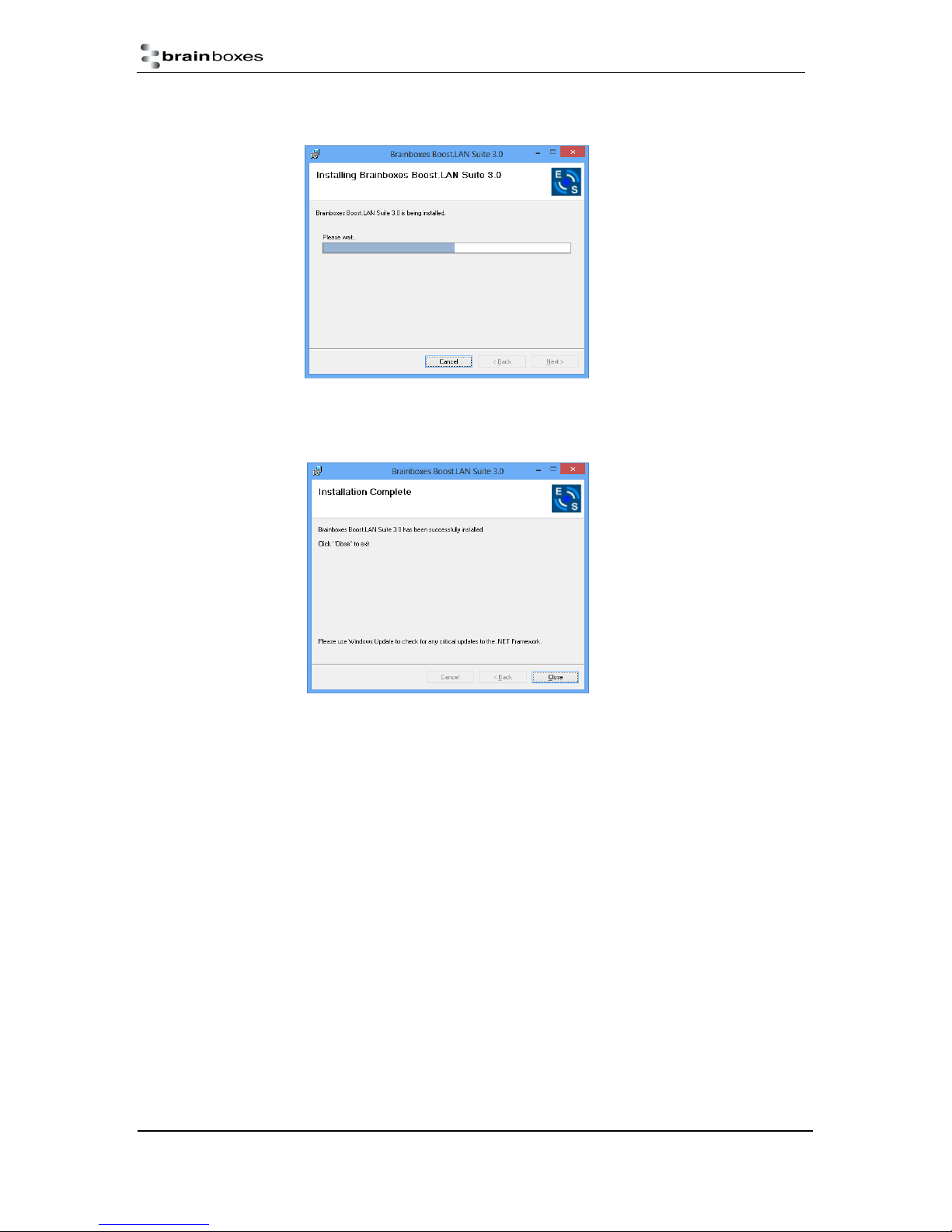
7. The software will now begin to install.
8. After the installation has finished, you will now see the below window. Click close.
ES Range Product Manual
© Copyright Brainboxes Limited 2013
Version 2.9
Page 16 of 66
Page 17
Windows Installation: Device Driver (Windows 8)
Double click the icon labelled “Boost.LAN Manager” on the desktop to open the application.
10. Click on the “File > Find Devices” in the top left hand side of the window. This will find any
Brainboxes Ethernet to Serial devices connected to your network.
You can find your Brainboxes ES-device by selecting a device and matching it with the
corresponding MAC address available in the left hand panel (see below). The MAC
address of your device is located on a sticker on the side of the ES device.
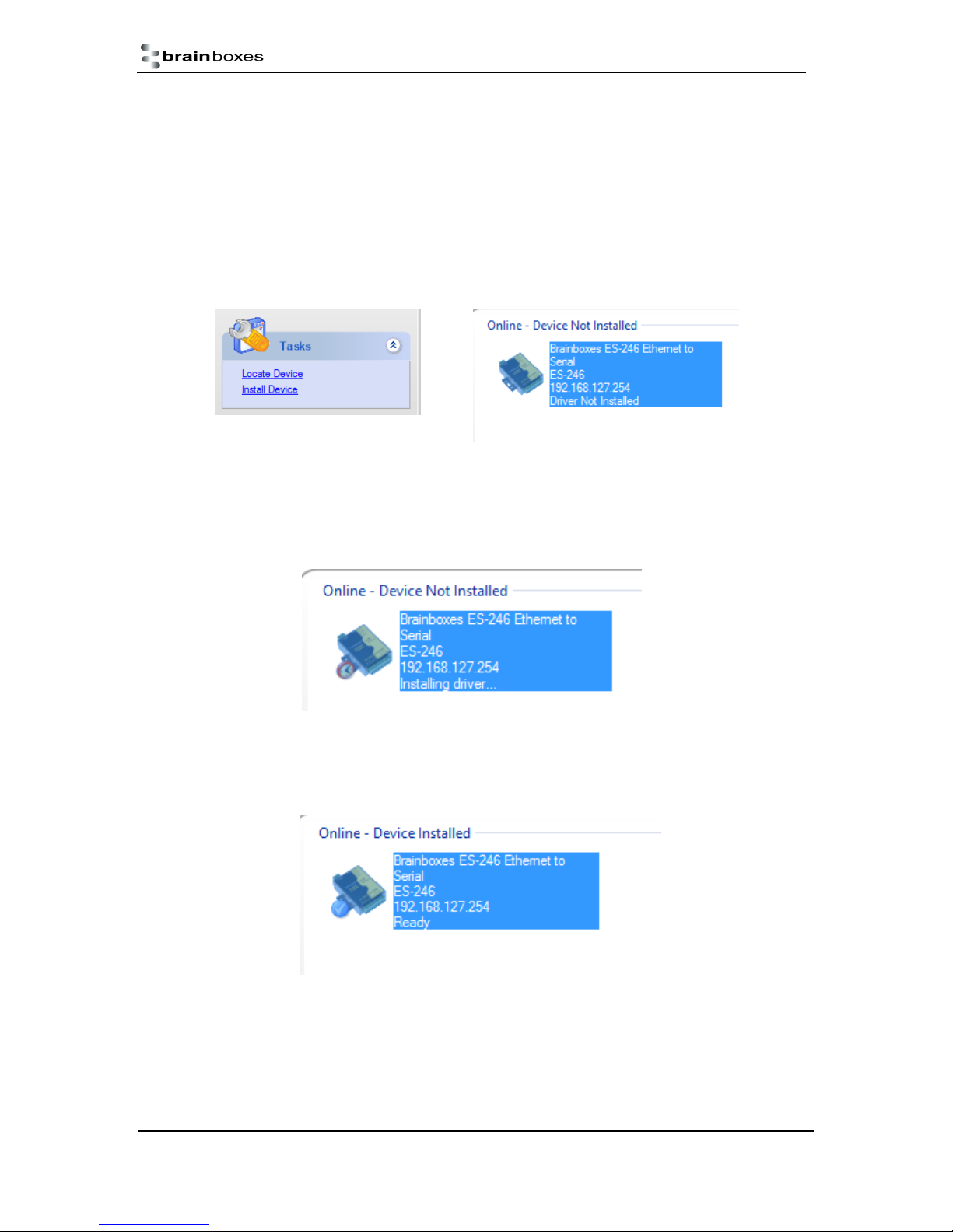
11. Once found, select the device and scroll to the “Tasks” section on the left hand panel.
Now click Install Device as shown below.
The device will now begin to install. During the device installation you will see a timer
symbol and the status of the device will be ‘Installing driver…’
12. In Boost.LAN Manger, the device will display a blue tick symbol showing that it is installed
and the status of the device will be ‘Ready’. Shown below.
13. You can check the COM Number of the Port, by following the instructions in Section 7
Finding your Brainboxes COM port If you need to change the COM port number, see
Section 9 Changing Your COM Label)
ES Range Product Manual
© Copyright Brainboxes Limited 2013
Version 2.9
Page 17 of 66
Page 18
5. RS-232 Settings (ES-246/ES-257/ES-701/ES279/ES-357/ES-020)
The RS-232 Standard
The RS-232 standard was introduced in 1962, it is now widely established. RS-232 is a slow speed, short
distance, single ended transmission system (i.e. only one wire per signal). Typical RS-232 maximum cable
length is 50 feet.
9 Pin D Serial Port RS-232 Cables
To connect to the RS-232 Serial Port you will need a cable terminating in a 9 way female D connector. It is
sound practice to use cables with screws fitted that will allow you to fasten the cable securely to the PC
card.
In general, you will need to make up a "cross-over" cable to correctly interface the PC to the RS-232 port of
another computer or device. Provided you have the pin outs and handshake requirements of both sides of
your RS-232 connection, the cross over cable becomes a matter of common sense. The cross-over cable
is simply to ensure that the right signals going out of one RS-232 port go into the appropriate lines of the
other RS-232 port.
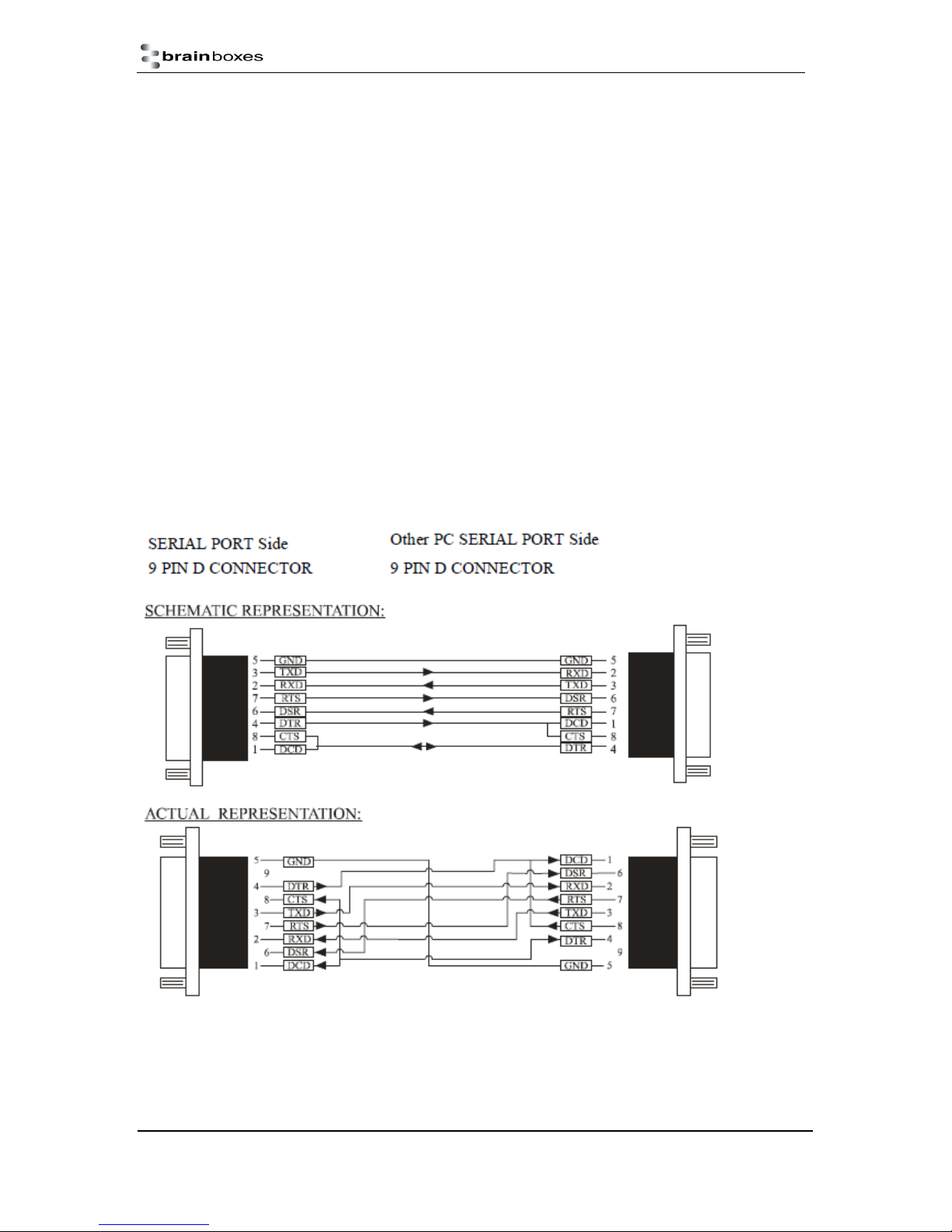
9 Pin D serial port connections to another PC
ES Range Product Manual
© Copyright Brainboxes Limited 2013
Version 2.9
Page 18 of 66
Page 19

Suppose we want to connect the Brainboxes Serial Port to the serial port of another PC. Connect the
earth lines. Line 5 of Serial Port 2, to lines 1 & 7 of the other PC. This gives the two devices a
common earth level.
Connect the Transmit and Receive lines together. Line 3, TXD, Port 2 goes to line 3, RXD, of the
other PC. Line 2, RXD, Port 2 goes to line 2, TXD, of the other PC. This allows each to receive the
data transmitted by the other.
Connect the Port 2 DTR line, pin 4 to the other PC DCD, pin 8 and CTS, pin 5, lines. Also, connect up
the other PC DTR line, pin 20 to the Port 2 DCD, pin 1 and CTS, pin 8, lines.
This allows the receiving device to signal when it can no longer accept data. The receiving device
sets DTR false when it is unable to receive any more data. The sending device reads DTR on its CTS
and DCD pins. It should stop sending when CTS goes false.
Connect the Port 2 RTS line, pin 7, to the other PC DSR line, pin 6. Also, connect the other PC RTS
line, pin 4, to the Port 2 DSR line, pin 6. This RTS line is used to let the other device know that it is
ready for data exchange.
ES Range Product Manual
© Copyright Brainboxes Limited 2013
Version 2.9
Page 19 of 66
Page 20
6. RS-422/485 Settings (ES-320/ES-313/ES-346/ES842/ES-357/ES-031/ES-042)
The factory default setting for the ES devices is RS-422 full duplex.
DTR/DSR Handshaking is not available on 422/485 ports.
The RS-485 standard talks about the differential pair as ‘Data A’ and ‘Data B’ but line driver chip
manufacturers use the labels ‘Data+’ and ‘Data-’. ‘Data A’ is the inverting pin ‘Data-’ and ‘Data B’ is
the non-inverting pin ‘Data+’
If you can’t get the connection to work it may be because you have mistakenly connected the lines the
wrong way round.
The RS-422 Standard
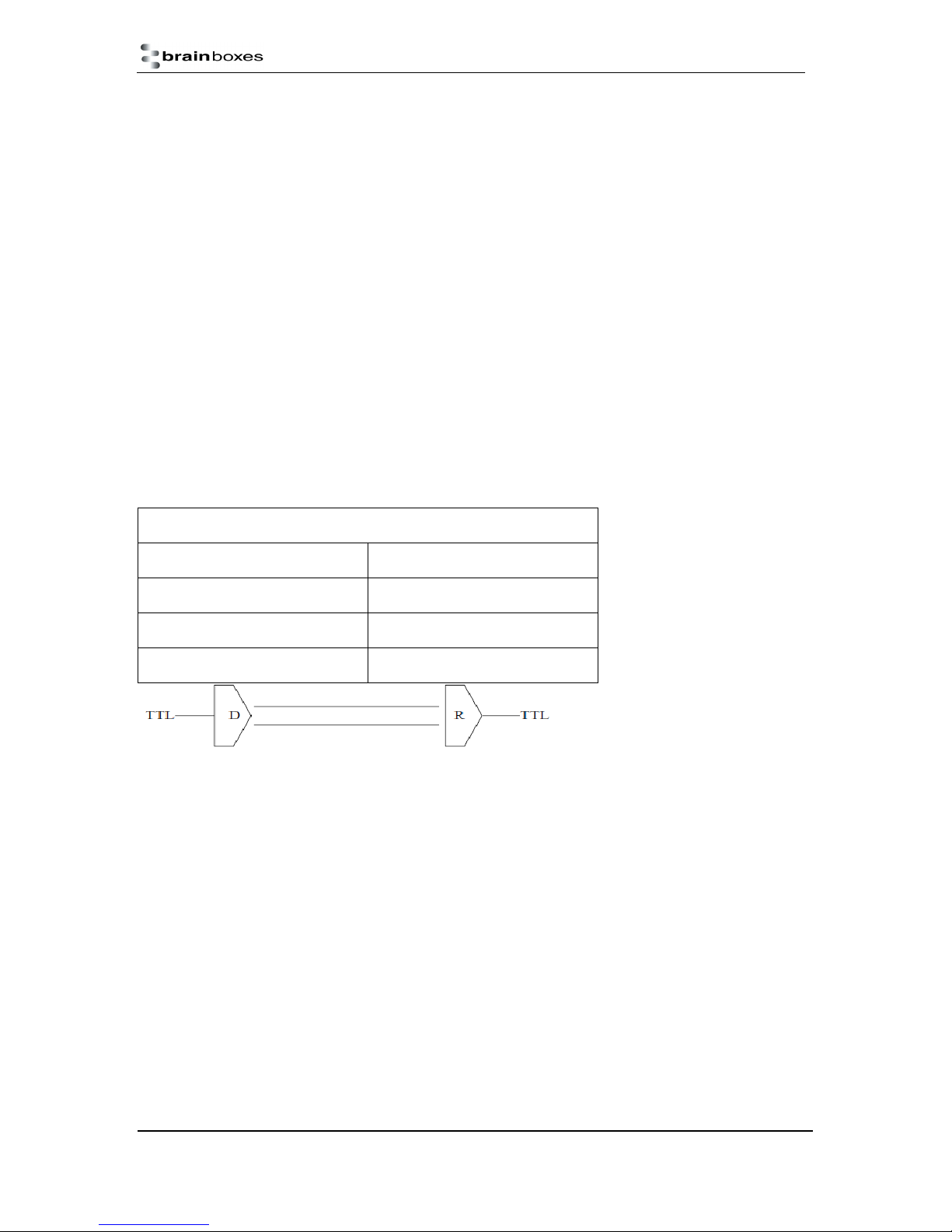
The RS-422 standard defines a serial communications standard. RS-422 is a high speed and/or long
distance data transmission. Each signal is carried by a pair of wires and is thus a differential data
transmission system. Over distances up to 40 feet the maximum data rate is 10 Megabits per second,
and for distances up to 4000 feet the maximum data rate is 100 Kilobytes per second. A 120-Ohm
resistor should be used to terminate the receiving end of the line. It is generally used between one
transmitter receiver pair to ONLY one other transmitter receiver pair, but each output can drive up to
10 receivers.
RS-422 Standard -1 Driver up to 10 Receivers
Line Length Max Data Rate
40 Feet = 12m 10 Mbits/sec
400 Feet = 122m 1 Mbits/sec
4000 Feet = 1219m 100 Kbits/sec
RS-422 Operation
Generally, in RS-422 systems all 8 signal lines from the 9 pin D connector participate in the data
transfer sequence, thus 4 twisted pair cables are used. One twisted pair carries the TXD data
outwards, one pair brings the RXD data inward, another pair carries the RTS handshake outwards
and the fourth pair brings the CTS handshake inwards. There is no need to carry the ground from one
device to another. This RS-422 arrangement allows data to be transmitted and received
simultaneously since each signal has its own data cable pair. In addition, the receiver can set RTS
true so telling the transmitter on its CTS input that the receiver is ready to accept data. In this way, no
data will ever be transmitted when the receiver is unable to accept it, due to a full input buffer etc. And
so no data will be lost.
RS-422 Full Duplex Mode
This mode is generally used between one transmitter / receiver to only one other transmitter /
receiver, but it is possible for each output to drive up to 10 receivers.
Generally, in RS-422 systems, all 8 signal lines from the 9 pin D connector or terminal block
participate in the data transfer sequence. Thus 4 twisted pair cables are used. One twisted pair
carries the TXD data outwards, one pair brings the RXD data inward, another pair carries the RTS
handshaking signal outwards, and the fourth pair brings the CTS handshaking signal inwards. There
is no need to carry the ground from one device to another.
ES Range Product Manual
© Copyright Brainboxes Limited 2013
Version 2.9
Page 20 of 66
Page 21
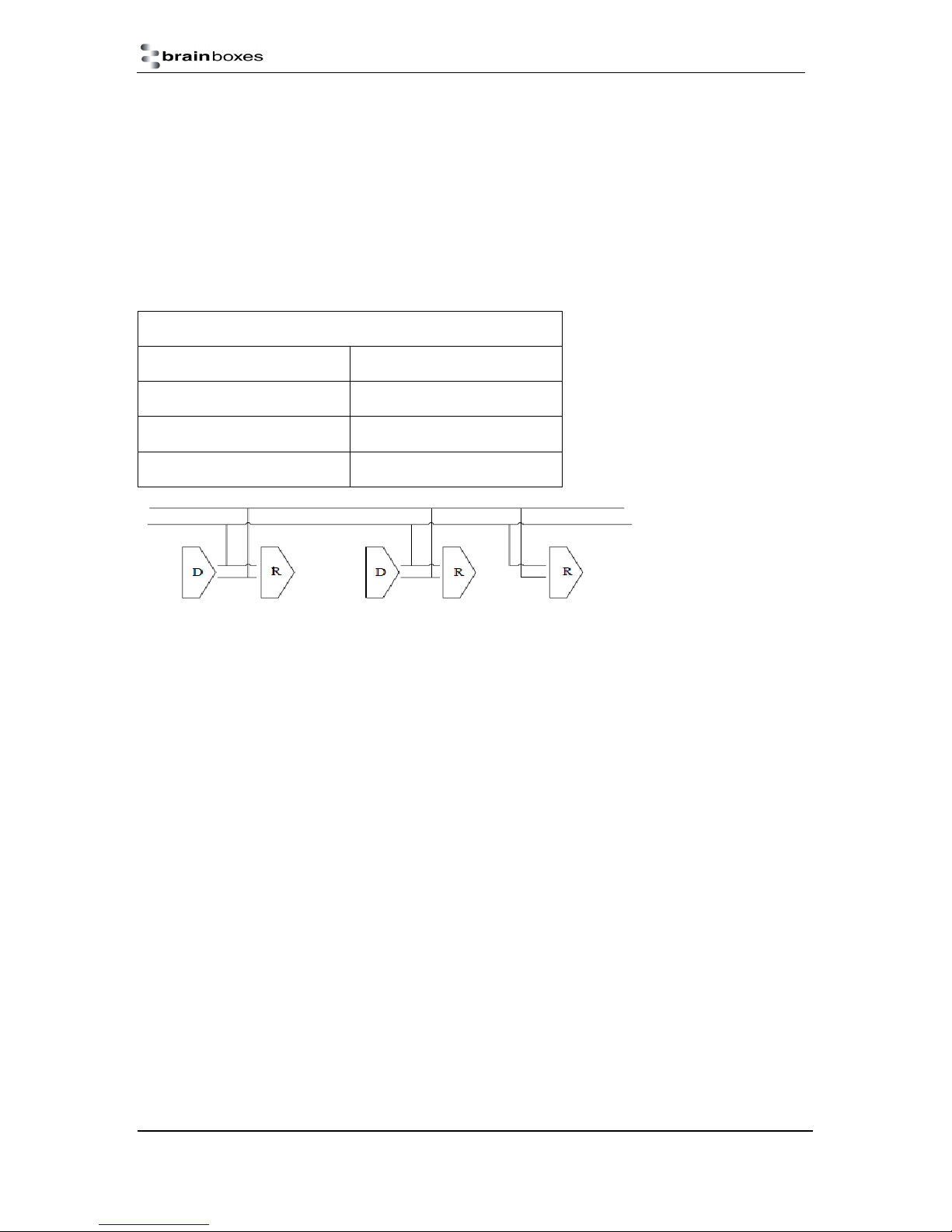
This mode is generally used between one transmitter / receiver to only one other transmitter /
receiver, but it is possible for each output to drive up to 10 receivers.
RS-485 Standard
The RS-485 standard is similar to the RS-422 standard upon which it is based. The main difference is
that up to 32 transmitter / receiver pairs may be present on the line at one time.
Generally not all the lines available on the 9 pin D connector or terminal block are used for RS-485
systems. The RTS+/- and CTS+/- lines, though driven by the device, are usually not connected. In
two wire Half-Duplex configuration, the TXD+ line is connected to RXD+, whilst the TXD- line is
connected to RXD-. Only one pair of twisted wire cable is used in RS-485 Half Duplex
communication.
RS-485 Standard - Up to 32 Driver/Receiver Pairs
Line Length Max Data Rate
40 Feet = 12m 10 Mbits/sec
400 Feet = 122m 1 Mbits/sec
4000 Feet = 1219m 100 Kbits/sec
RS-485 Operation
The RS-485 standard is intended for up to 32 driver receiver pairs on the bus. The line drivers used in
the RS-422/485 card are designed to work correctly in both RS-422 and RS-485 systems. The main
difference therefore is in how the system is implemented. Though the card uses a 9 pin D connector,
in general, not all the lines are used for RS-485 systems. The RTS+/- and CTS+/- lines, though driven
by the card, are usually not connected. In two wire, Half-Duplex configurations the TXD+ line is
connected to the RXD+ whilst the TXD- line is connected to the RXD-, only one pair of twisted wire
cable is used in RS-485 Half Duplex communications. The hardware handshaking performed by the
CTS+/- and RTS+/- lines in RS-422 systems are handled by a software protocol in RS-485 systems.
In situations where more than one device may transmit data on the shared data line, each cards RTS
line is used as a gating signal to enable the TXD driver only when that card needs to transmit data.
This mechanism prevents bus contention caused by multiple transmitters holding the line in opposing
states. Our cards have a facility which automatically “gates” the RTS line, thus enabling the
transmitter independently of any software. The three wiring schemes given described below are: -
1. RS-485 One Talker Many Listeners (HALF DUPLEX)
2. RS-485 Many Talkers Many Listeners (HALF DUPLEX.)
3. RS-485 Many Talkers Many Listeners (FULL DUPLEX.)
ES Range Product Manual
© Copyright Brainboxes Limited 2013
Version 2.9
Page 21 of 66
Page 22
RS-485 One Talker - Many Listeners, Half Duplex.
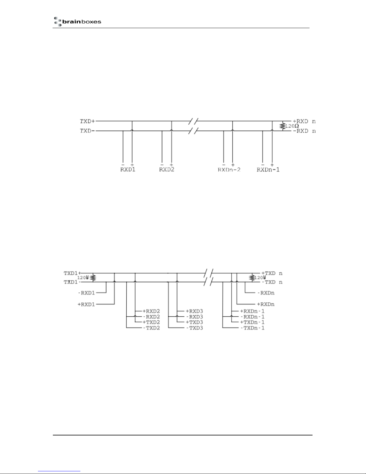
There are several schemes for connecting RS-485 devices depending on the characteristics of the
system. In many cases there will be only one device, which can transmit, data and all the others
simply listen to it. This scheme is used for theatrical lighting intensity control in the DMX512 standard.
This is shown below. There is NO multiplexing of the TXD and RXD lines. Data is only flowing one
way, from PC outwards, and is thus a Half-Duplex configuration; only one twisted pair cable is
needed.
Note: The Receiver end of MAIN line terminated in characteristic impedance by ONBOARD resistor
networks stubs off the main not terminated. In the above scheme, one RS-485 device is talk only, it
transmits data, but it does not receive any. The other RS-485 devices are received only; they do not
transmit any data at all.
RS-485 Many Talkers - Many Listeners, Half Duplex.
Another popular RS-485 layout is for multiple talkers and multiple listeners. This is shown below. This
is also known as "party line" transmission. It is imperative to have some method of preventing two
devices trying to drive the data lines at the same time. The normal method is to use the RTS line as a
talk enable. The RTS line should go true immediately prior to the data transmission and go false
immediately after the last byte in the stream is sent.
Note: BOTH ends of MAIN line terminated in characteristic impedance, stubs off main line not
impedance, since both ends receive. The twisted pair ends are wired to both RXD+ & TXD+ and
RXD- & TXD- at each RS-485 device!
RS-485 Many Talkers - Many Listeners, Full Duplex.
The RS-485 many talkers, many listeners, Full Duplex system can be used when all the
RS-485 devices have separate Transmit and Receive channels. There is NO multiplexing of the TXD
and RXD signals on the same device. This system is especially useful when there is no flow control
available on the PC, usually due to the use of a third party communications program that prevents the
use of the RTS signal as a "transmit enable" control. It can be used in the following situations:-
a) The PC is connected to only ONE RS-485 device.
ES Range Product Manual
© Copyright Brainboxes Limited 2013
Version 2.9
Page 22 of 66
Page 23
b) The PC is communicating with several RS-485 devices that are each able to recognize and
respond to their own unique address. The RS-485 devices only drive their TXD lines when they are
responding to requests from the PC to send data. In effect, the RS-485 device’s address and the
command it receives is used to control access to the devices TXD channel.
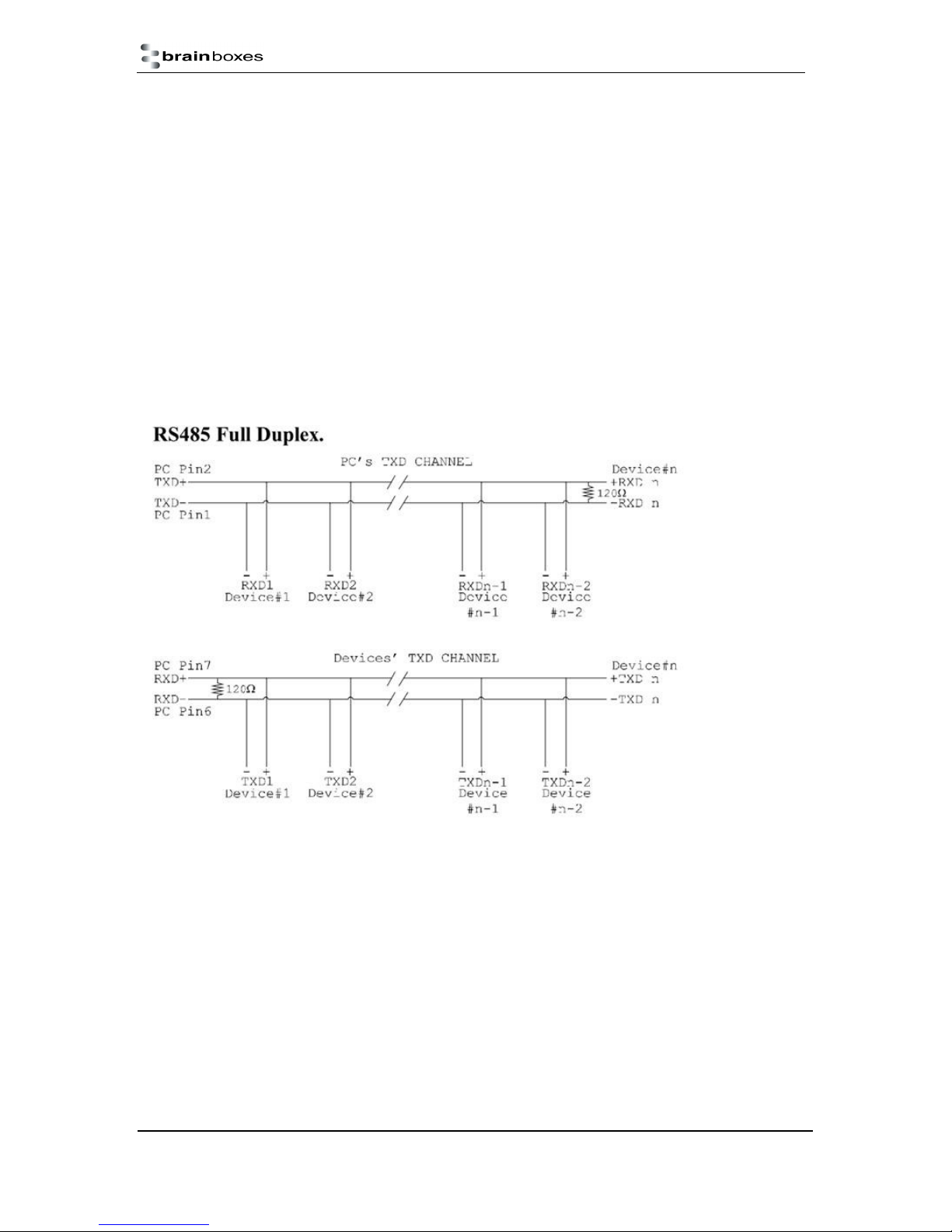
This is a Full Duplex system. Two twisted pair cables are required. One twisted pair, is the PC’s TXD
channel, it carries the data sent from the PC’s TXD outputs to the RXD inputs of each of the RS-485
devices. The second twisted pair, is the Devices TXD channel, it carries the data sent from each of
the devices’ TXD outputs to the RXD inputs of the PC. The advantages of this system are great, since
no new communications, software is needed, and the PC can talk and listen at the same time. In
effect, the handshaking is performed by the intelligence of the RS-485 devices attached to the PC.
When wired as below, the PC can transmit data at any time and all the RS-485 devices #1 to #n
simultaneously receive it. Only one of the RS-485 devices may talk, i.e. transmit data, at any one
time. Each RS-485 device recognizes commands and data addressed to it; it only talks when the PC
commands it to do so. When the RS-485 device receives the command to talk from the PC, it gates
its TXD drivers on, sends the data down the device TXD channel, and disables its TXD drivers. The
other RS-485 devices remain in the ‘receive only’ mode when they are not being addressed, they do
not transmit any data at all.
RS-422 Serial Port Cables
Use screened twisted pair Belden cable 9729 and 9829, L type 2493 and 2919 cable to make the RS422 connection. Unscreened Belden type 8795 may also be used in less noisy environments. The on
board resistor networks terminate the receiving end of the twisted pair cable in its characteristic
impedance.
RS-485 Serial Port Cables
For best noise immunity use twisted pair cables to make the RS-485 connection. In Half Duplex wiring
only 1 twisted cable pair is needed. Two twisted pair cables are needed for Full Duplex
communications. Use screened twisted pair Belden cable 9729 and 9829, UL type 2493 and 2919
cable to make the RS-485 connection. Terminate the twisted pair cable.
ES Range Product Manual
© Copyright Brainboxes Limited 2013
Version 2.9
Page 23 of 66
Page 24
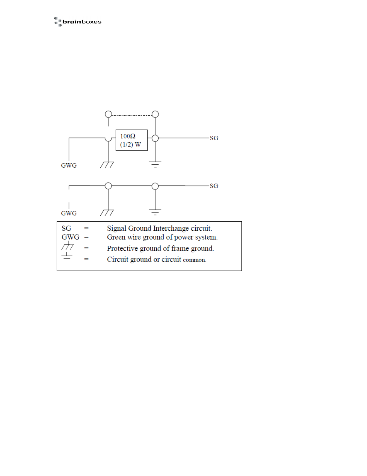
Optional Grounding Arrangements
Proper operation of the cable circuit, according to TIA EIA: 485 A (1995) requires that the cable
ground shield is not connected directly to the equipment ground shield. A current limiting resistor
should be used in series with the shield to avoid possible large current flow due to differences in
ground potential. Any one of the methods shown below can do this.
The circuit common of the equipment is connected to protective ground, at one point only by a 100 Ω,
±20% resistor with a power dissipation rating of 1/2W. An additional provision may be made for the
resistor to be bypassed with a strap to connect signal common and protective ground directly together
when specific installation conditions necessitate.
Configuration A
Configuration B
RS-485 Line Failsafe Biasing
Since RS-485 devices have to take turns to send data on the bus there are times when the bus lines
are idle, (not driven by any device) and they float to an indeterminate state generating false data. To
solve this; at each end of the RS-485 bus, add a pull up and a pull down resistor to put the line into a
known, good state during idle times. Brainboxes products have factory fitted bias resistors that are
jumper enabled.
RS-485 Line Termination
Reflections at the end of the twisted pair cable run can interfere with data on the line and so can
cause errors.
Brainboxes products have factory fitted termination resistors that are jumper enabled. Fit the jumper
ONLY if this device is at the end of the cable.
These are the two main wiring schemes:
RS-485 One Talker Many Listeners (Half Duplex)
RS-485 Many Talkers Many Listeners (Half Duplex)
Please see Section 20 for the pin outs of RS-422 and RS-485 for your ES Device.
RS-485 Full Duplex Mode (ES-313, ES-320, ES-346 & ES-842)
ES Range Product Manual
© Copyright Brainboxes Limited 2013
Version 2.9
Page 24 of 66
Page 25
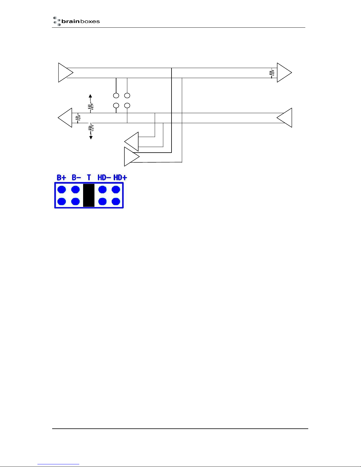
T R
R
T
R T
H-
This mode is generally used between one transmitter and many receivers. It uses 2 twisted pair
cables, one carries the TXD data outwards and one brings the RXD data inward.
3V3
B+
H+
B-
GND
For full-duplex operation, the HD+ and HD- jumpers must not be
fitted. For optimal signal quality, fit the T jumper but not the B+ and Bjumpers.
RS-485 Full Duplex (ES-357)
To set the ES-357 to full duplex mode, this needs to be done by changing the settings for the COM
port. To open RS-422/485 settings:
1. Double click the port entry in Boost.LAN Manager
2. Go to the Port Settings tab
3. Click Advanced
4. Go to the RS-422/485 Settings tab.
5. The drop down list allows users to choose the desired RS-422/485 operations mode.
6. Select “RS-422 full duplex mode” for Full Duplex communications.
ES Range Product Manual
© Copyright Brainboxes Limited 2013
Version 2.9
Page 25 of 66
Page 26
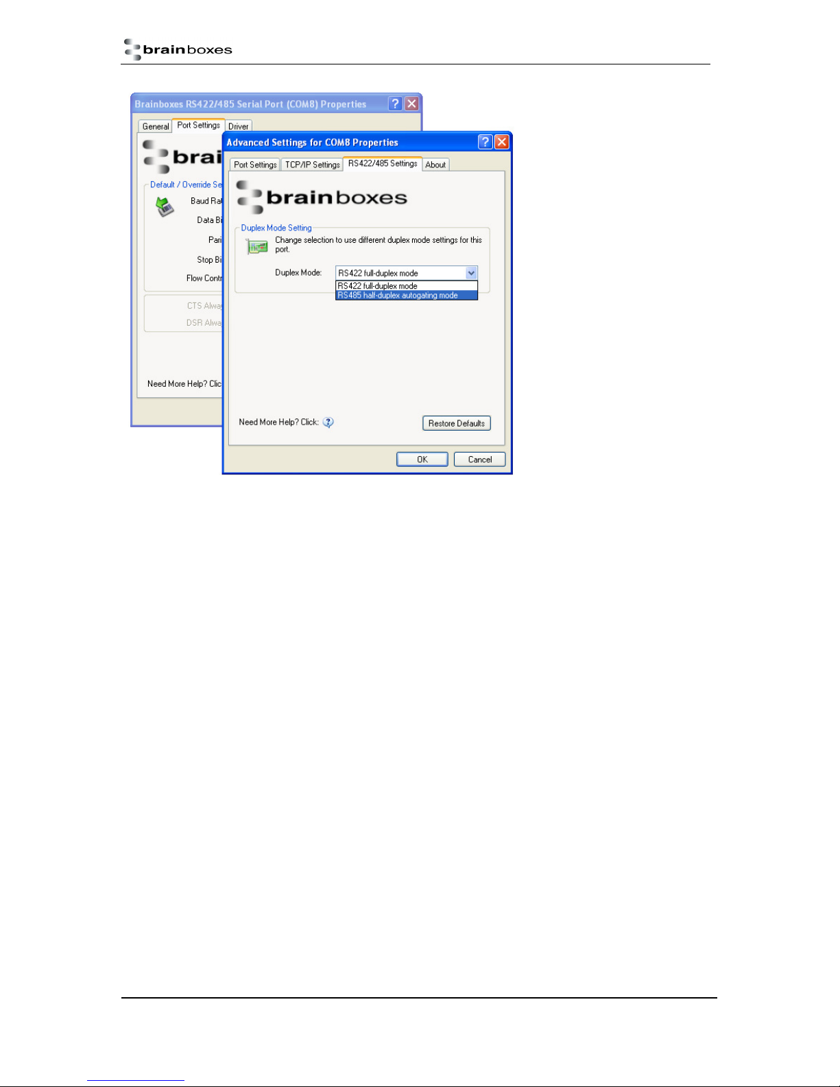
Restore Defaults: Pressing this button will reset all settings on this Property Page back to the factory
defaults of this device. The default settings for this Property Page are “RS-422 full duplex mode”.
RS-485 Half Duplex Autogating Mode (ES-357 Only)
For the RS-422/485 port on the ES-357, there is an additional tab in the Advanced Settings of the
Windows COM port to allow you to change duplex mode to half duplex autogating mode. The factory
default setting is RS-422 full-duplex mode.
When the duplex mode is set to half duplex autogating the ES device will automatically detect the
start of the PC’s transmissions and will gate the PC’s transmitter onto the twisted pair cable. It will
then automatically detect the stop bit being sent and gates the port off the twisted pair cable.
ES Range Product Manual
© Copyright Brainboxes Limited 2013
Version 2.9
Page 26 of 66
Page 27
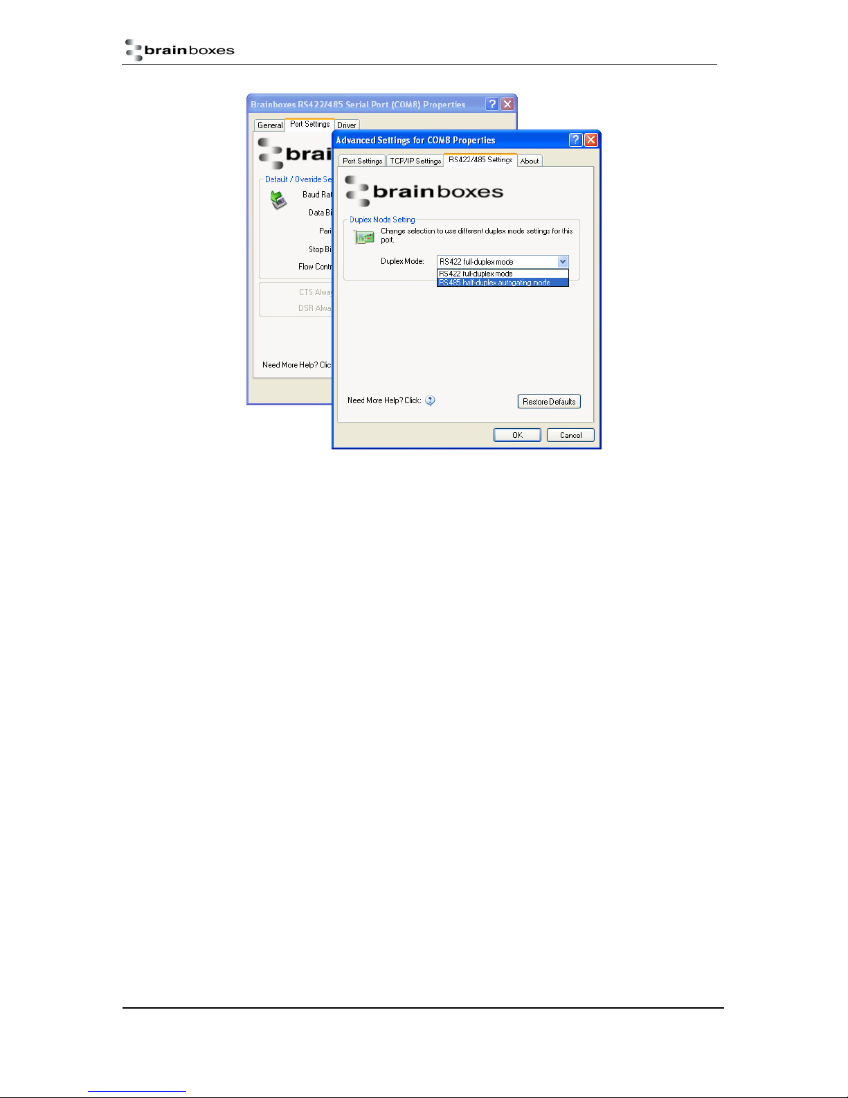
To open RS-422/485 settings:
1. Double click the port entry in Boost.LAN Manager
2. Go to the Port Settings tab
3. Click Advanced
4. Go to the RS-422/485 Settings tab.
5. The drop down list allows users to choose the desired RS-422/485 operations mode.
6. Select “RS-422 full duplex mode” for Full Duplex communications.
7. Select “RS-485 half duplex autogating mode” for Half Duplex communications.
Restore Defaults: Pressing this button will reset all settings on this Property Page back to the factory
defaults of this device. The default settings for this Property Page are “RS-422 full duplex mode”.
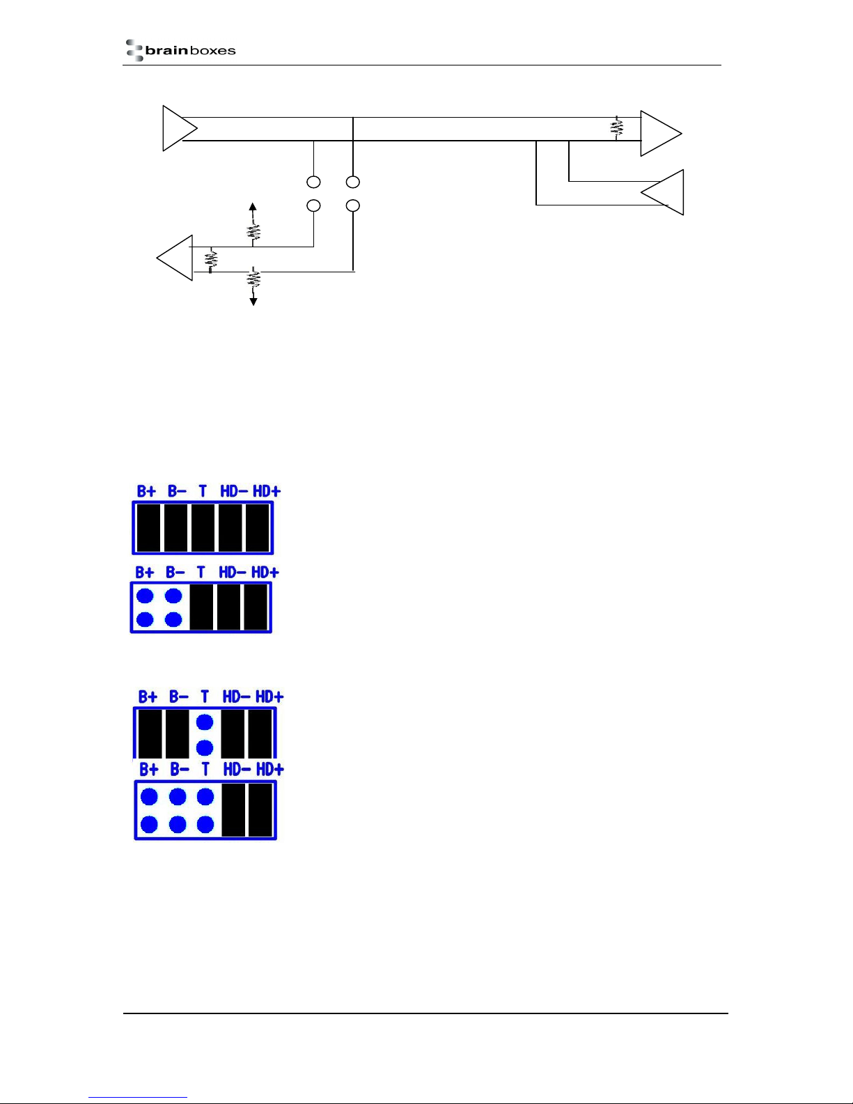
RS-485 Half Duplex Mode (ES-313, ES-320, ES-346 & ES-842 only)
For half-duplex operation, the transmit and receive lines of the port need to be connected together
making it a 2 wire system. This can be done by fitting the HD+ and HD- jumpers onto the headers
inside the ES device box.
Half-duplex links usually need biasing resistors fitted at some point on the link. These resistors are
used to hold the signal lines in a known state when the transmitters are off. If these resistors aren’t
used it is likely that random data will be received when no transmitter is turned on. This is because of
noise which is picked up along the cable which causes the lines to float to unknown states. The B+
resistor pulls the ‘+’ line up to 3V3 and the B- resistor pulls the other ‘– ‘line down to ground.
It doesn't matter which device on the link has them, as long as one of them does. Biasing resistors
can be connected by fitting the B+ and B- jumpers onto the headers on the ES device PCB.
The T jumper connects in a termination resistor. Termination resistors are used on the end devices in
the link to absorb the signal and stop echoes of the data being reflected back onto the transmission
line.
For point-to-point links (two devices linked), this should be fitted for both devices. For a multi-drop
bus (more than two devices linked on the same cable), the termination should be present at the two
end devices but not at any of the devices in between.
ES Range Product Manual
© Copyright Brainboxes Limited 2013
Version 2.9
Page 27 of 66
Page 28
T
R
T
R
To access the headers, the case of the ES-313 or ES-320 needs to be opened.
Jumpers can be placed vertically across any of the 5 sets of pins explained as thus below:-
T
3V3
GND
H+ H-
B+
B-
B+ and B- = are bias resistors.
T = Termination resistor
HD+ and HD- = are half duplex pins.
So the possible configurations are:
Half-duplex point-to-point link, when no other biasing is present:
And when biasing is already present somewhere.
For a half-duplex multi-drop bus, if the device is at the end of the bus then use the same jumper
configurations as for a half-duplex point-to-point link, above.
For a half-duplex multi-drop bus, where the device is not at the end of the
bus but somewhere in the middle.
Or depending on whether biasing is already presents somewhere.
ES Range Product Manual
© Copyright Brainboxes Limited 2013
Version 2.9
Page 28 of 66
Page 29
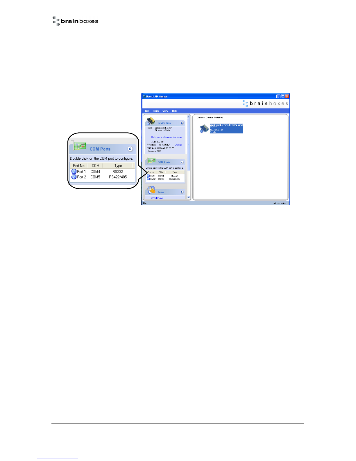
7. Finding your Brainboxes COM port
1. Open Boost.LAN Manager (Found by clicking Start All Programs Brainboxes
Boost.LAN Boost.LAN Manager)
2. Click on your ES Device
3. Find the “COM ports” section on the left hand pane.
To change your COM label, see Section 9 - Changing your COM label
ES Range Product Manual
© Copyright Brainboxes Limited 2013
Version 2.9
Page 29 of 66
Page 30

Using the ES-device with your Equipment
If you are using a COM port based application
1) Ensure the ES device is powered up.
2) Ensure the ES device is connected to the network (Ethernet LED should be ON)
3) Ensure the ES device is connected to your Equipment via the correct serial port (i.e. RS-232
port if using an RS-232 device, or RS-422/485 if using an RS-422/485 device)
4) Ensure the ES device is installed on the PC you wish to control the communications to the
equipment with.
5) Open your application on the PC which talks to your equipment.
6) Select the COM port associated with your device.
7) Click “Open” or “OK” to start communications as you would usually when communicating to
the equipment using your existing direct serial cable connection.
8) Check the Port LED on the ES device is now ON. This indicates the port is open and is
receiving data to and from your equipment.
9) Continue to use your application as normal. If you have problems with your application
communicating to the equipment, see troubleshooting guide.
If you are using a socket based application
1) Ensure the ES device is powered (the power LED should be ON)
2) Ensure the ES device is connected to the network (Ethernet LED should be ON)
3) Ensure the ES device is connected to your Equipment via the correct serial port (i.e. RS-232
port if using an RS-232 device, or RS-422/485 if using an RS-422/485 device)
4) Determine the IP address and port number for each serial port you’ll be communicating to.
Use Boost.LAN Manager to find your ES device by matching the MAC address on the side of
the device with the MAC address in Boost.LAN Manager.
5) Open your application and enter the IP address of the ES device and port number for each
serial port you’ll be communicating to.
6) Click “Open” or “OK” to start communications as you would usually when communicating to
the equipment using your existing direct serial cable connection.
7) Check the Port LED on the ES device is now ON. This indicates the port is open and is
receiving data to and from your equipment.
8) Continue to use your application as normal. If you have problems with your application
communicating to the equipment, see troubleshooting guide.
ES Range Product Manual
© Copyright Brainboxes Limited 2013
Version 2.9
Page 30 of 66
Page 31

8. Testing the ES device
In order to prove that your Brainboxes Ethernet to Serial device is functioning correctly, you can
perform a loopback test to check the Transmit and Receive lines are working and that you can access
the device over the network.
Perform a loopback: A loopback test will verify that your ES device is able to Transmit and
Receive Data. The Transmit and Receive lines will need to be connected so that any data
sent out of the ES device is then received back on the same Port. Please see the following
FAQ from our website for instructions on how to test your Serial port.
http://www.Brainboxes.com/faq/items/how-do-i-test-my-Brainboxes-card-to-make-sure-itsworking
If you are still experiencing problems, see the Troubleshooting Section in this manual.
ES Range Product Manual
© Copyright Brainboxes Limited 2013
Version 2.9
Page 31 of 66
Page 32
9. Advanced Configuration
ES devices store the device settings inside the device. When you access the webpage it gets these
settings from the device. When you access the driver it gets the settings from the device too. If you
have Boost.LAN closed and change a setting on the webpage, the device driver will not know that the
settings have been changed on the webpage until Boost.LAN is opened. When Boost.LAN first opens
it will update the settings of any installed devices. Therefore you need to open Boost.LAN manager
after changing a setting on the webpage in order for the driver to use this new setting.
IP Addressing
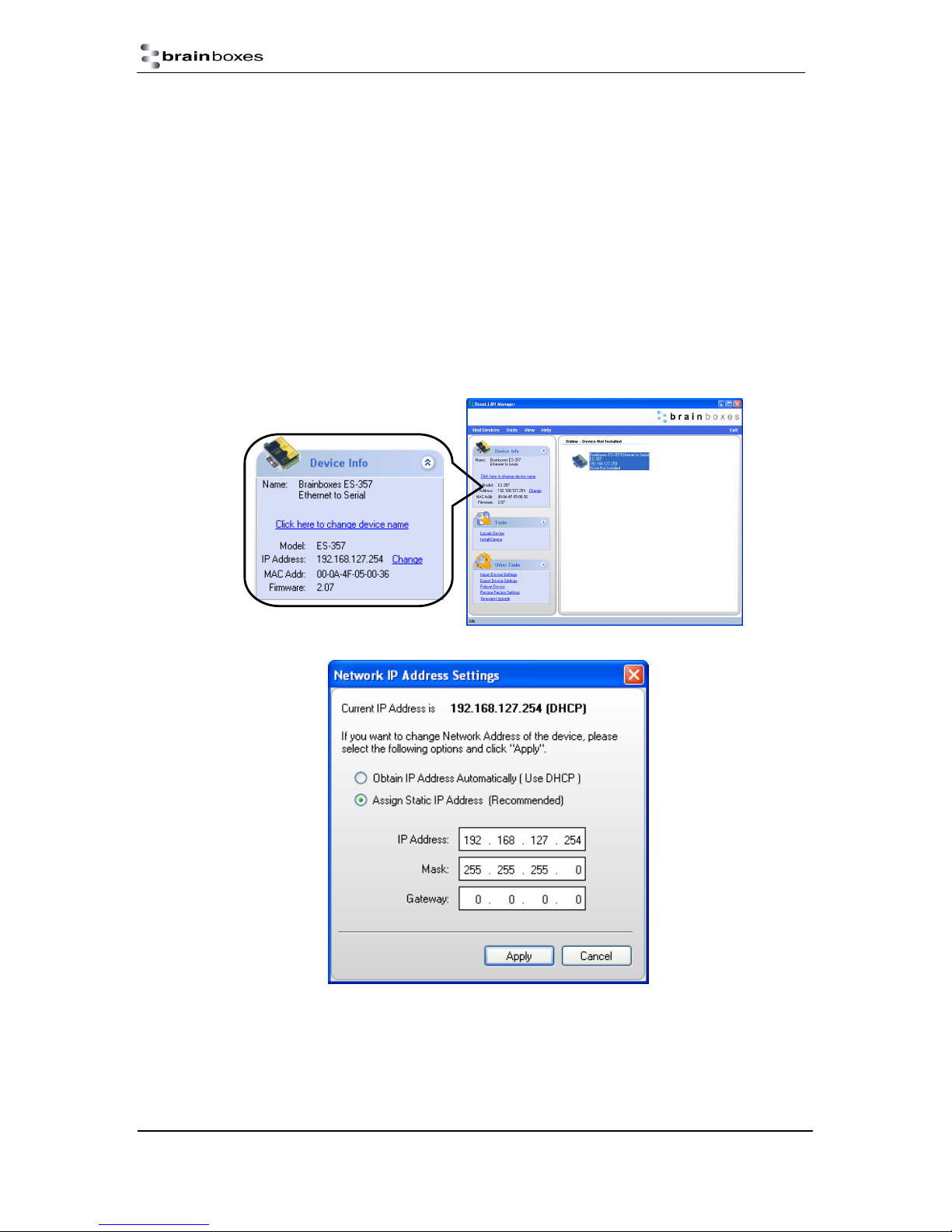
The IP settings can be easily changed by clicking the “Change” link available in the “Device
Info” section on the left hand panel of Boost.LAN Manager.
This will bring up the following dialogue box.
As mentioned in the “Features” section of this manual, the ES device is shipped in DHCP
Mode. On connecting to the network, the device automatically checks if it is connected to a
DHCP Server. If this is the case, the DHCP server will allocate an IP address automatically to
the ES device.
ES Range Product Manual
© Copyright Brainboxes Limited 2013
Version 2.9
Page 32 of 66
Page 33
If no DHCP Server is detected within 60 seconds (e.g. you are using a direct cable connection
to the PC), the ES device will default to the IP address specified in the static IP Settings as
shown above. By default, this is 192.168.127.254.
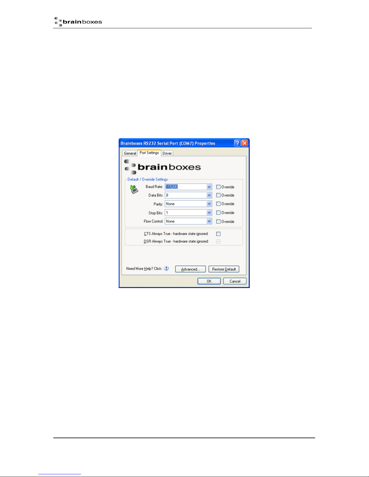
Port Settings
The Port Settings allow you to set Default or Override Settings for the serial communication and how
to deal with incoming hardware handshaking events.
• To open ‘Port Settings’, open Boost.LAN Manager and Double Click on the Brainboxes COM
Port Entry.
• Then Click on the ‘Port Settings’ tab.
• All options can be selected from the Dropdown Menus. In addition, you can enter a non-
standard value into the Baud rate
NB – Once the desired settings have been achieved, you must click OK to activate them. At any time
click the ‘Restore Default’ button to return to the original setup.
Default / Override Settings
• The “Default Settings” will be set if an application does not specify the serial settings when it
opens the COM Port.
o This is sometimes the case with old Legacy applications and you will need to choose
these settings to match the communications that you wish to use.
o The majority of Applications will specify what Serial Settings they wish to use. In this
case, it will not matter what the Default settings are, as the Port will be opened with
the Application’s Settings.
• When the ‘Override’ box is checked next to the Default Setting, the Port will communicate at
this setting whether an application has requested it or not.
ES Range Product Manual
© Copyright Brainboxes Limited 2013
Version 2.9
Page 33 of 66
Page 34
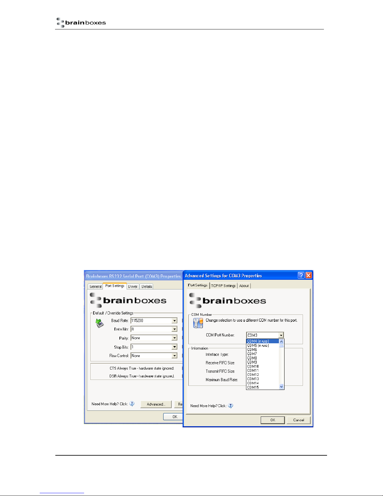
o For example, this will enable you to force baud rates that your application does not
allow you to select. This can be useful for interfacing to equipment which uses higher
baud rates or unusual baud rates, which your application does not support.
o In a case where you want to use hardware handshaking, but your application is not
capable, you can select CTS Always True – Hardware state ignored and choose to
Override it.
o NB with the use of Override Settings, you need to ensure that the equipment you are
connecting to be setup to match the communications settings you are forcing.
CTS / DSR Always True
• CTS and DSR are incoming hardware handshaking lines. This means they receive signals
from the connected device which tell the Ethernet to Serial device when it is and isn’t OK to
send data.
o Sometimes these signals may want to be ignored. By forcing CTS or DSR True, the
Ethernet to Serial device will ignore those signals and always send data.
o These settings are especially helpful when CTS and DSR are not physically
connected (such as in a 3 wire setup) and it is not acceptable for the data flow to stop
and start due to arbitrary variances on the unconnected signal lines.
o NB: Some ES devices do not support RTS/CTS or DTR/DSR handshaking and as a
result, “CTS Always true” or “DSR Always true“will be enabled by default. Please
check the product datasheet for your device to see what hardware handshaking is
available.
Changing your COM label
1. If you need to change the COM label, Double click on the Port entry in Boost.LAN Manager
2. Click on the ‘Port Settings’ tab and click Advanced
ES Range Product Manual
© Copyright Brainboxes Limited 2013
Version 2.9
Page 34 of 66
Page 35
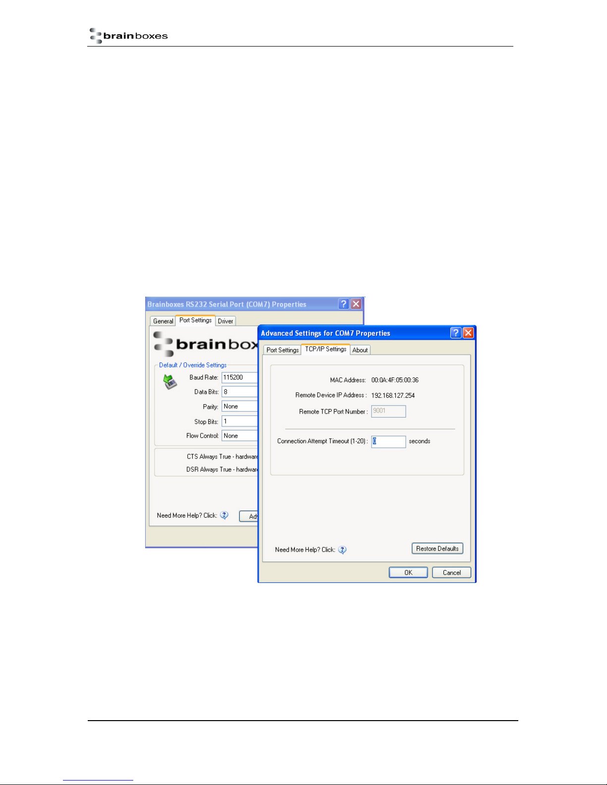
3. A new COM Port label can be selected from the dropdown menu. Click OK to set the new
COM Label.
4. If the COM Port number is labelled “in use”, it is either currently used by a COM Port present
on the system, or is reserved for a device which is not currently present. It is possible to
select this COM number and force the change, if you are sure it is not required by any other
device.
Advanced Settings – TCP/IP Settings
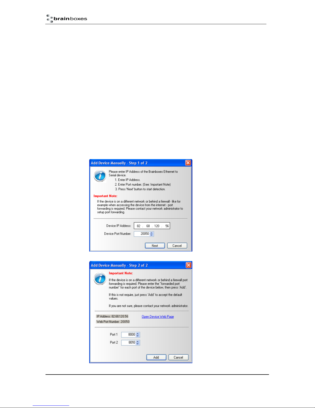
The TCP/IP Settings for the Brainboxes COM Port allow you to obtain the ES device’s TCP/IP
settings without having to go to Boost.LAN Manager or the Webpage interface. Some users may
prefer this accessibility.
To open Advanced Settings, open the Port Settings (as described in section 9) and click the
Advanced button.
Select the ‘TCP/IP Settings’ tab.
ES Range Product Manual
© Copyright Brainboxes Limited 2013
Version 2.9
Page 35 of 66
Page 36

Device MAC Address: This is assigned when the device is manufactured.
Remote Device IP Address: If the device is set to DHCP mode the IP address will be
automatically assigned by the DHCP server. If it is set to static, this is set by the user either
with the Webpage interface or using Boost.LAN Manager. This is useful for finding out the IP
address of the ES device to access web page or a COM port.
Remote TCP Port Number: Number set by user for accessing Port on ES device. This is set
to 9001 by default.
Connection Attempt Timeout: This is set to “0” by default. If “Connection Attempt Timeout”
is other than “0”, the Telnet connection to the port will be disconnected automatically (i.e.
other devices can access this port) after being idle (i.e. no data is being received or sent to
and from the port) for a time ranging from 1 – 20 second/s as specified. The LED for the port
will go off at this point. If “Connection Attempt Timeout” setting is “0”, the port will need to be
disconnected manually by the user.
The default settings have been carefully selected and should provide the right settings for the majority
of users.
Alternate Access Methods
There are three methods to view and configure your Ethernet Device once it’s installed on the target
PC. Which method to use depends on personal preference and convenience.
NB: Only certain settings can be configured using the Web Page Interface
Boost.LAN Manager: This is the application that is installed initially to find the device and
install the COM port drivers. Configuring from here is the recommended option for ease and
convenience, as it centralises all Ethernet to Serial devices.
Windows Device Manager: This is the standard Windows Control Panel that allows users to
view and control all hardware attached to a computer. The Ethernet to Serial ports can be
configured from here also.
Web Page Interface: This allows the Ethernet to Serial device to be accessed from any PC
within your network as it does not require Boost.LAN Manager. Configuration from here is
recommended for socket based applications only. See Section 10 for more information about
the web page interface.
Proxy Server Settings
If you have a proxy server enabled on your PC this will restrict access to the web page interface. You
may need to add the ES device to the Proxy Server’s exceptions list. If you need help doing this
contact your network administrator.
Device Swapping
In the unlikely event of a device failing, it can be easily replaced by swapping it with a device which
has the same IP address. This is particularly useful when using a large number of ES devices
together which have already been installed and setup and are already communicating with
peripherals. The faulty device can be replaced without having to set up and install a new device. To
set the device to the same IP address use the web page interface or Boost.LAN to set the IP address
to the static address of the device you are replacing. For more information on IP address
configuration see Section 9.
ES Range Product Manual
© Copyright Brainboxes Limited 2013
Version 2.9
Page 36 of 66
Page 37
Remote Access
The Remote access feature of the ES devices allows access to the device over the internet or from a
different network. The device can be accessed either through the webpage interface, or through
Boost.LAN device manager. To access the ES device remotely, you will need the IP address of the
router and have port forwarding set up on your router for the device and the ports on your device. If
you need assistance setting up port forwarding on your network, contact your network administrator.
Once you have the IP address and port forwarding numbers of the device and the ports, you can
either access the device through the webpage or through Boost.LAN.
Adding a remote device using Boost.LAN Manager
1. To access the device through Boost.LAN go to Tools and then click ‘Add Device Manually’.
2. Enter the public IP address of your router into the Device IP Address field, and the port
forwarding number into the Device Port Number field.
3. Click the ‘Next’ button.
ES Range Product Manual
© Copyright Brainboxes Limited 2013
Version 2.9
Page 37 of 66
Page 38
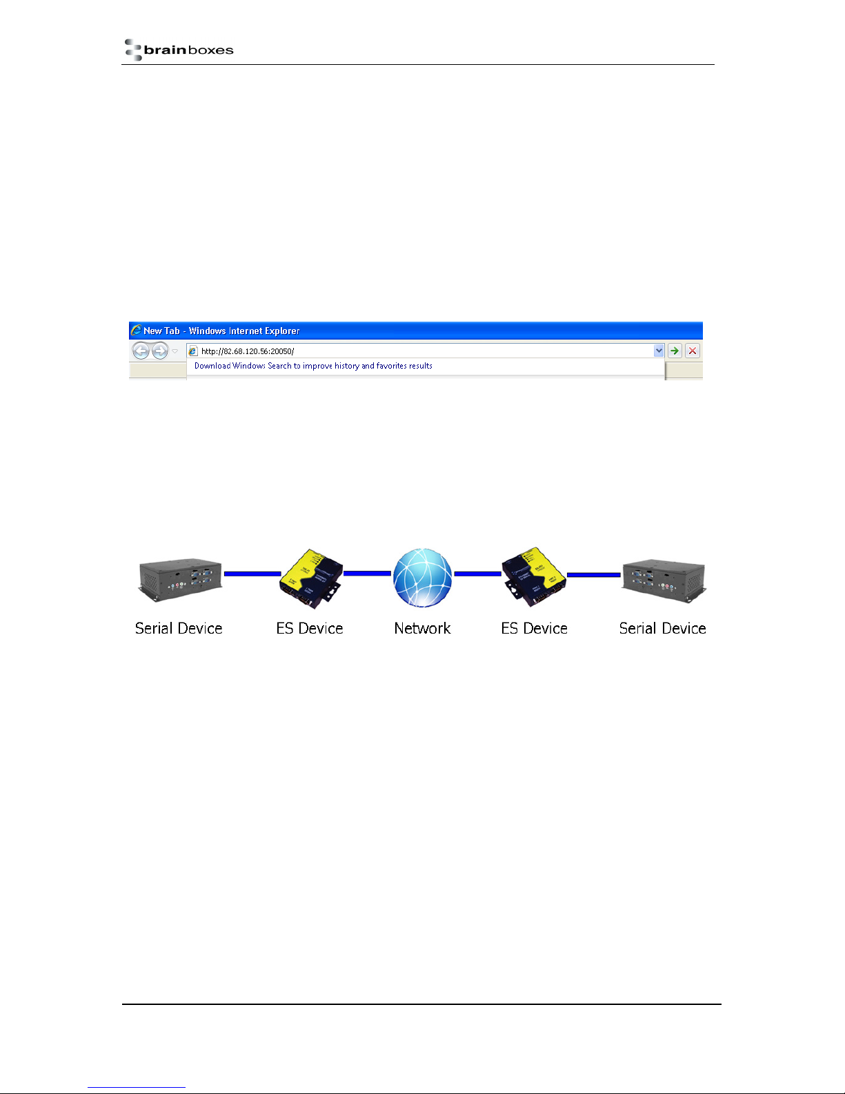
4. Enter the port forwarding numbers for Port 1 and Port 2 and then click the ‘Add’ button. The
device will then appear in the Boost.LAN manager window. It can then be installed and used
as if it were on a local network.
5. Enter the port forwarding numbers for Port 1 and Port 2 and then click the ‘Add button
Remote Access Using Web Browser
To access the ES device through the webpage you will need the IP address of your router and the ES
device’s port forwarding number. Type this address into the navigation bar with a colon then the port
forwarding number. For example http://82.68.120.56:20050/ See the example in the screen shot
below.
Serial Tunnelling
Brainboxes Ethernet to Serial Devices have a feature called serial tunnelling. Serial tunnelling
connects two devices together to create a serial tunnel which extends the serial link over an Ethernet
connection. When serial data is sent, it is converted to Ethernet packets by one Ethernet to Serial
device, and then transmitted over the network, then unpacked and converted back to serial data by
the other Ethernet to Serial device. An example of tunnelling is shown in the diagram below.
Serial tunnelling is set up using the webpage interface. In the following instructions there are two
devices which are referred to, the local side which is the device that you are connecting from, and the
remote side which is the device you are connecting to.
1. Go to the web page interface of the Local ES Device using a web browser.
2. Navigate to the page of the serial port you want to use.
3. At the bottom of this web page is the device tunnelling section.
4. To connect tunnelling tick the enable box and select if you want the device to be master or
slave. Enter the Remote IP Address and Remote TCP Port number of the ES device you want
to connect to and tick the ‘Enable’ check box.
ES Range Product Manual
© Copyright Brainboxes Limited 2013
Version 2.9
Page 38 of 66
Page 39
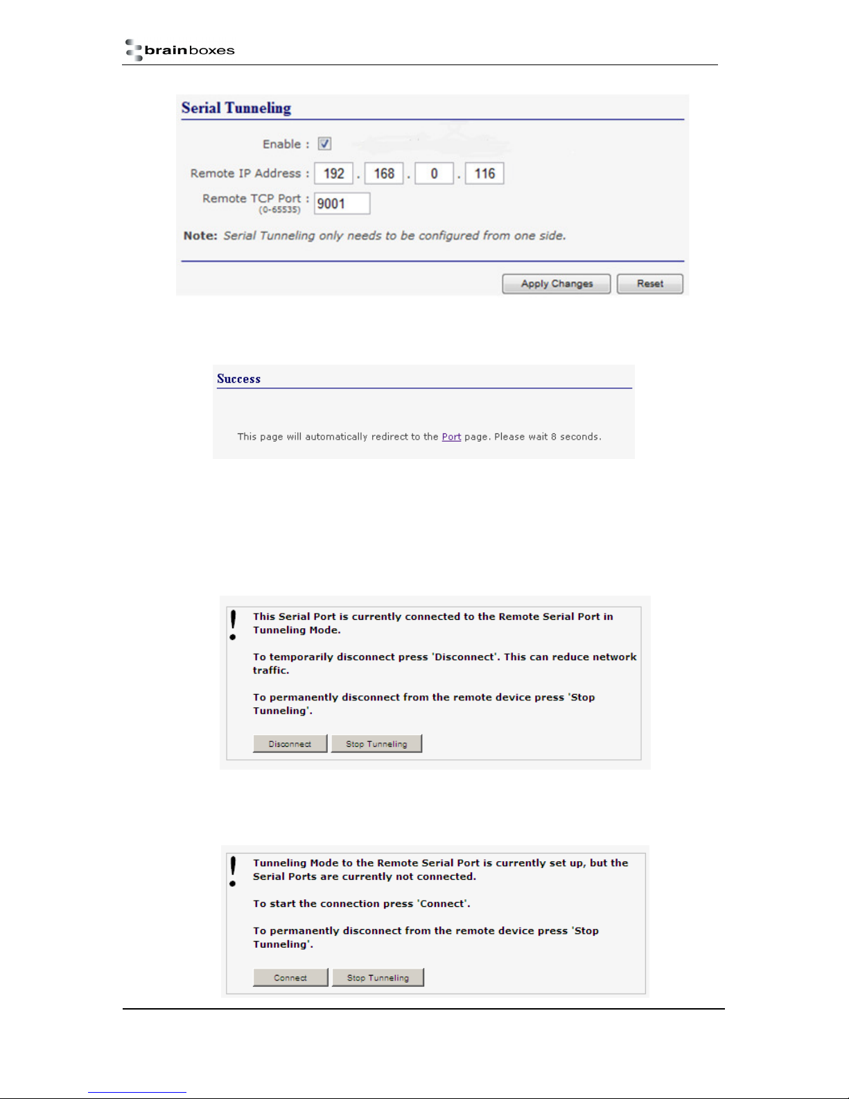
5. Click the ‘Apply Changes’ button and you will be taken to a page which will display a success
page. You will be redirected to the port page after the countdown timer has finished.
6. The devices will now be in tunnelling mode.
7. On the Local device port webpage you will see displayed the device tunnelling section with
two buttons, ‘Disconnect’ and ‘Stop Tunnelling’. By clicking the ‘Stop Tunnelling’ button this
will disconnect the ports on the remote and local side and put both of the devices into an idle
state. If the ‘Disconnect’ button is clicked the remote side port will be disconnected and go
into the idle state, but the local side will remain in tunnelling mode.
8. When the remote port is disconnected the local port webpage shows a ‘Connect’ button.
When this button is pressed the remote device will be connected to the local device and
tunnelling will be connected.
ES Range Product Manual
© Copyright Brainboxes Limited 2013
Version 2.9
Page 39 of 66
Page 40
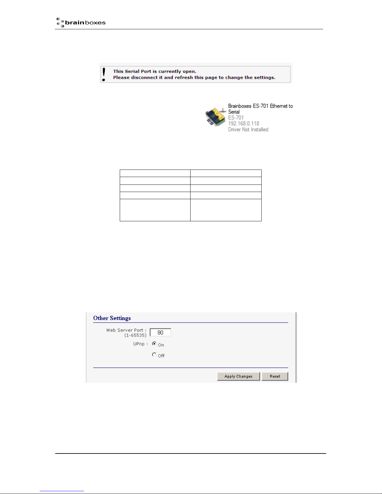
9. On the remote device port webpage interface, on the Serial port that is tunnelling it will show
that the port is connected.
10. In Boost.LAN Manager, the symbol in the
image to the right will be displayed when a
device in is connected in tunnelling mode.
Firewall Exceptions and Port Numbers
When using the ES devices with a firewall you may need to manually add the exception entries and
port numbers to the firewall list. Listed below are the default port numbers and the firewall
exceptions.
Program Name Default port number
Device Web Server 80
Serial Port 1 9001
Serial Port 2 9002
67 (BOOTP Server)
Firmware Upgrade
Default Windows Firewall Exception entries:
• Brainboxes Boost.LAN Suite
• Brainboxes Boost.LAN Suite (Device discovery) (except Windows XP 32 & 64 bits)
• UPnP Framework (Windows XP 32 & 64 bits)
• Network Discovery (Windows 7 or later)
68 (BOOTP Client)
69 (TFTP Port)
UPnP on/off
Turning the UPnP of your device off or on can only be done using the web page interface and will
mean that the ES Device won’t be broadcasting on the network. This means you won’t be able to
search for the device using Boost.LAN Manager. You can however add the device manually if you
know the IP address and port number.
ES Range Product Manual
© Copyright Brainboxes Limited 2013
Version 2.9
Page 40 of 66
Page 41
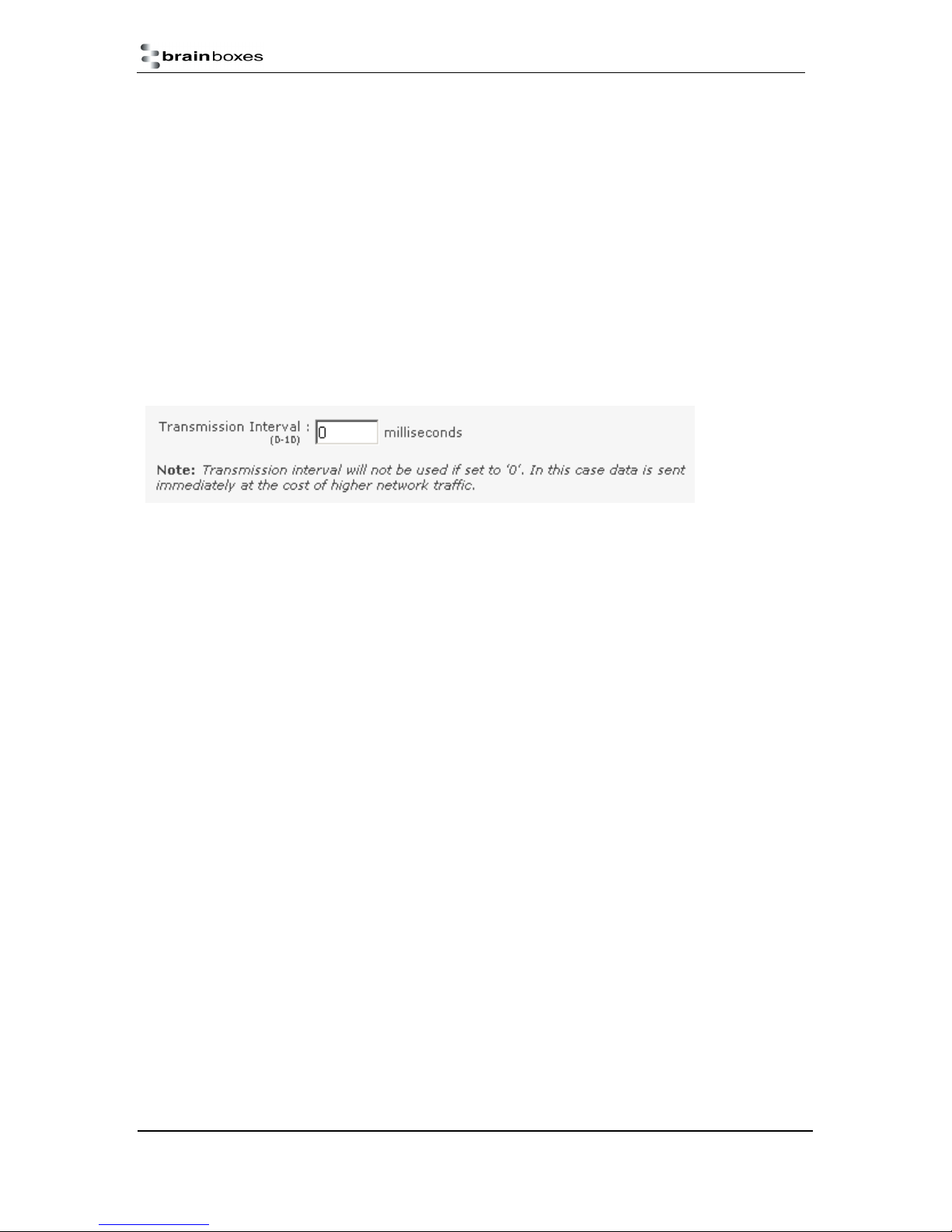
It is recommended when using Boost.LAN Manager that you install the driver before turning off the
UPnP. This will ensure that when Boost.LAN is opened, the installed device will be displayed in the
Boost.LAN device manager panel.
Transmission Interval
The transmission interval can be set via the web configuration page. The factory default for the
Transmission Interval is set to 0. With the transmission interval set to 0 milliseconds, the incoming
data is transmitted straight away, in small bytes which cause a lot of network traffic and high CPU
usage on the PC receiving the data.
When there is a transmission interval set, there is a delay on sending the data. The first byte of data
that comes in is sent immediately but after this no further data is sent until the transmission interval
time has passed. The ES device then accumulates any further bytes of data and then sends them all
together in one large chunk after the transmission interval, reducing network traffic and CPU usage.
ES Range Product Manual
© Copyright Brainboxes Limited 2013
Version 2.9
Page 41 of 66
Page 42
10. Web Page Interface
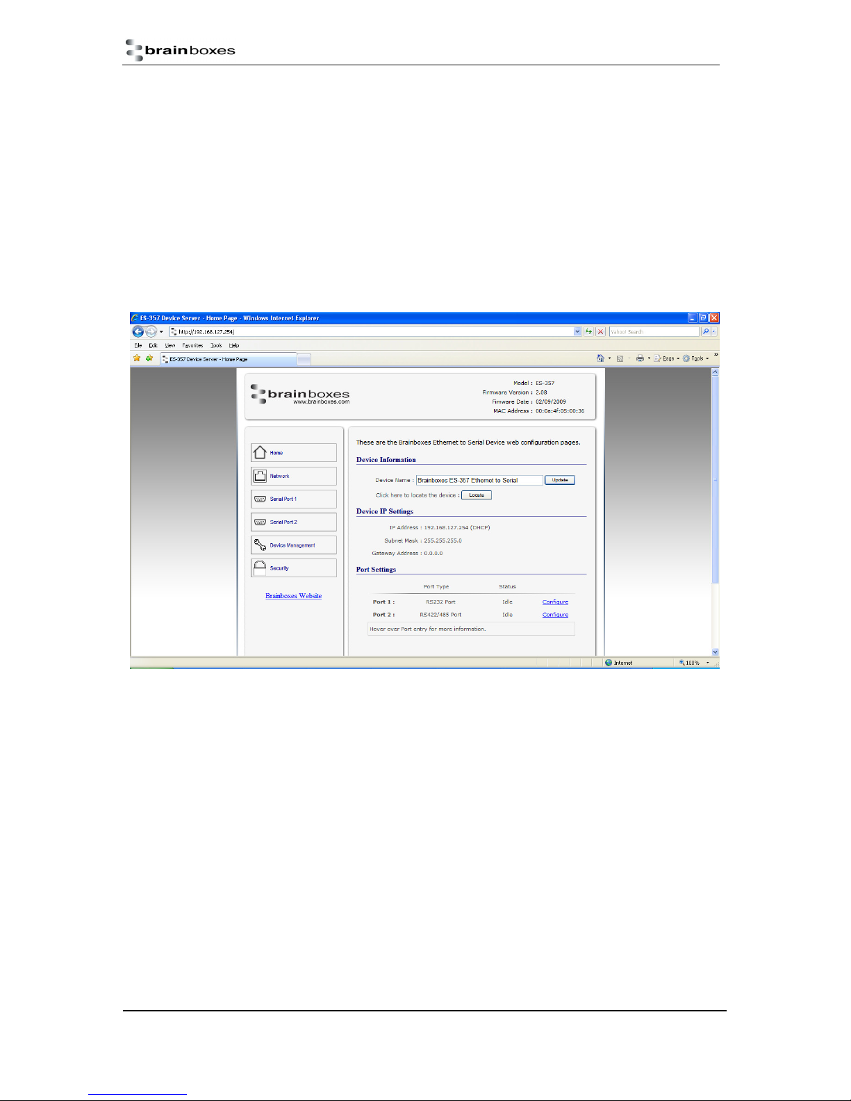
The ES device can be accessed from any PC within your network as it does not require Boost.LAN
Manager.
To access the ES device web page:
1. Obtain the IP Address of the ES device via the Boost.LAN Manager
2. Type the IP address in your internet browser and hit Enter
3. The ES device webpage interface should appear allowing you to view and configure the ES
device settings.
NB: Please bear in mind, if you are using the Brainboxes Windows driver to create a COM port
then port settings detailed on the web page are overridden in the driver. The settings available
through the web page only apply to socket based applications.
ES Range Product Manual
© Copyright Brainboxes Limited 2013
Version 2.9
Page 42 of 66
Page 43

The webpage provides:
Summary of current IP and Serial Port Settings (available on Home Page)
Separate pages to configure each serial port.
Serial Port Settings:
o Baudrate (Maximum 1M baud)
o Databits (8, 7, 6, 5)
o Stopbits (1, 2)
o Parity (None, Even, Odd, Mark, Space)
o Handshaking (RTS/CTS, DTR/DSR, Xon/Xoff)
o Duplex Mode (Full Duplex, Half Duplex)
For details of Full Duplex and Half Duplex communications, see Section 6
Networking Protocol settings for each Serial Port:
NB: If you are using the Brainboxes Windows driver to create a COM port then the
driver will use Telnet + COM port Control Mode (Server) regardless of the protocol
setting set on the webpage.
o RAW TCP: Data sent over the network is the same as the data sent over the serial
link. Any configuration of the serial port settings will need to be set via the web page.
o Telnet + COM port Control Mode (Server): This is based on the RFC2217
standard which lets the serial ports settings be configured dynamically. Data is then
encapsulated over serial link
o Telnet
IP Settings
Device Tunnelling Setup
Device Management to:
o Restart ES device
o Restore factory settings
Security settings:
o Enable Administrator account
o MAC Address restriction
o Enable user account
ES Range Product Manual
© Copyright Brainboxes Limited 2013
Version 2.9
Page 43 of 66
Page 44
11. Security
Anyone with access to the network can access the webpage of your ES device and change its
settings. To prevent this from occurring, there are security features available on the device that can
restrict access to certain web pages to account holders only.
Administrator Access Settings
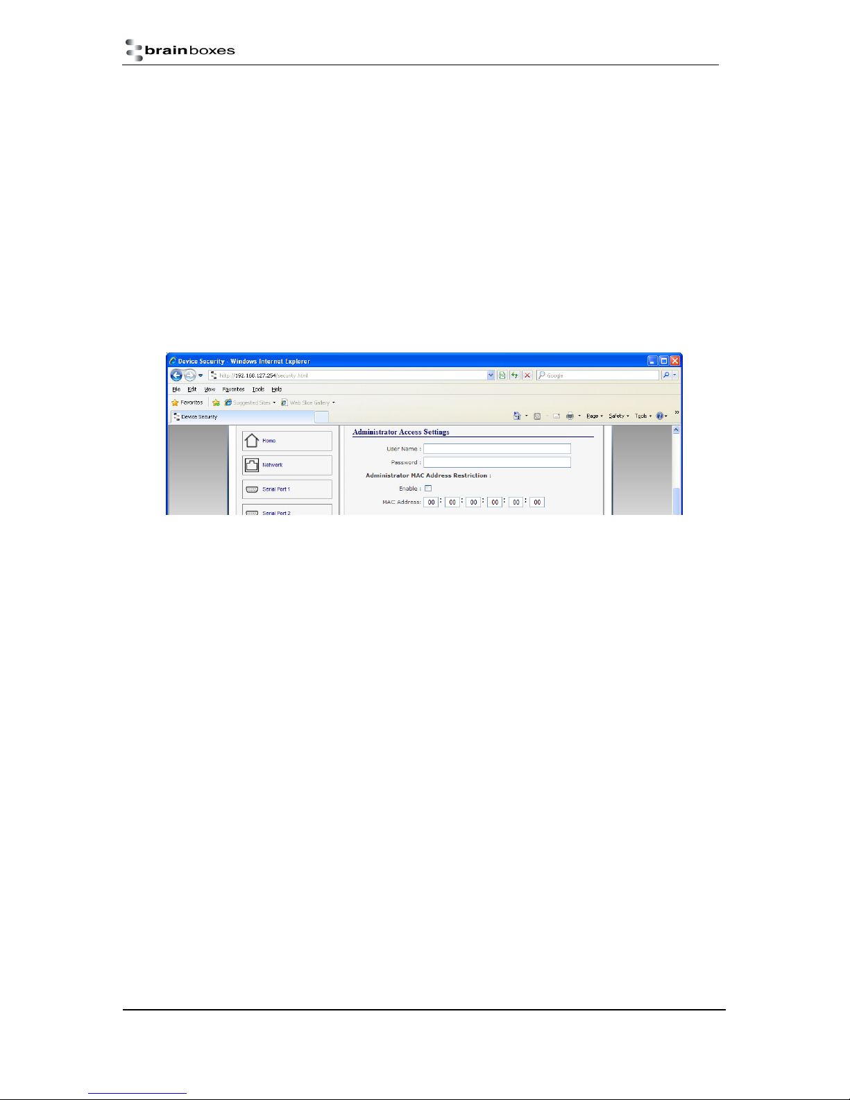
Creating an Administrator account restricts access to the Security Page to the Administrator
account holder. All other pages are still accessible to other users.
To create an Administrator account:
1. Open the device’s Webpage by typing the device’s IP address into a browser
2. On the left hand menu, click Security. This will open the device’s Security Settings page.
4. Enter a username and password in the “Administrator Access Settings” section
5. Click “Apply Changes” at the bottom of the page.
6. To access the security page of the device via the webpage again, you will be prompted with a
log in prompt. Only the administrator will have access to this page.
User Access Settings
Creating a User Access account restricts complete access to the web page interface of your
device to a User Account or Administrator account holder. No configuration page can be
accessed without logging in using the user or administrator log on credentials.
A User account may be created without an Administrator account.
Both an Administrator and User Account can be set up on the same device. If both are setup,
the Security Page will be restricted to the Administrator account holder only. If just a User is
setup, then the User has access to all areas.
To create a User account:
1. Open the device’s Webpage by typing the device’s IP address into a browser (see
Section 10 for further details).
2. On the left hand panel, click Security. This will open the device’s Security Settings page.
3. Enter a username and password in the “User Access Settings” section
ES Range Product Manual
© Copyright Brainboxes Limited 2013
Version 2.9
Page 44 of 66
Page 45
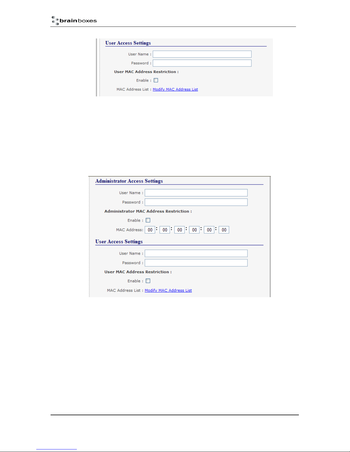
4. Click “Apply Changes” at the bottom of the page.
5. To access the web interface of the device again, you will be prompted with a log in
prompt. Only an administrator or user will be able to log in.
MAC Address restriction
In addition to Administrator and User accounts to restrict access to users with the correct log on
credentials, there is a feature called “MAC address restriction”
MAC address restriction is available under both Administrator and User settings.
Enabling MAC address restriction means access to the device will be limited to Administrators
or Users with the MAC addresses specified in the MAC Address list. For example
o The Administrator/User is expected to always log in from the same MAC address. Even if
the correct username and password are entered, access will be refused if the MAC
address is different.
WinSock and UPnP communications are also restricted to specified MAC addresses.
Administrators are automatically Users, so there is no need to add the Administrator MAC
address to the User MAC address list.
With MAC address restriction enabled, the device will only appear visible on specified MAC
addresses.
ES Range Product Manual
Version 2.9
© Copyright Brainboxes Limited 2013
Page 45 of 66
Page 46
Restricting “Reset/Restore Default”
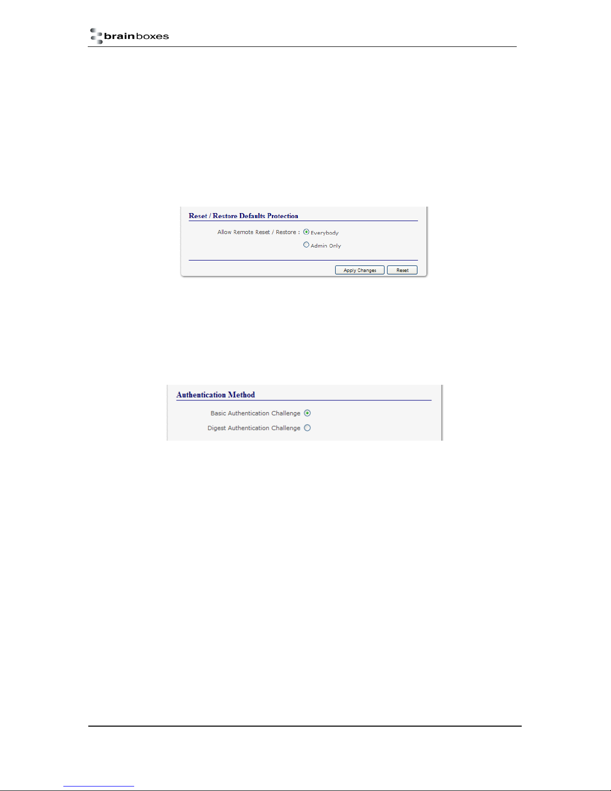
Once an Administrator account is set up, access to the “Device Management” page to “Reset or
Restore Default settings” is still available to all users. Alternatively, if both an Administrator and User
are set up, both the Administrator and User can access the page.
To avoid any unauthorised “Resetting or Restoring to Default”, the following features are available.
Everybody: This will restrict the ability to reset or restore to those with an administrator or
user account
Admin only: This will restrict the ability to reset or restore to the administrator only.
NB: You must set up an Administrator account or a User account (or both depending on
requirements) for “Reset/Restore Defaults Protection” to take effect.
Authentication Method
There are two authentication methods:
Basic Authentication Challenge: Log on credentials are passed as plaintext over the
network.
Digest Authentication Challenge: Log on credentials are encrypted when sending over the
network and as such, more secure than Basic Authentication Challenge.
ES Range Product Manual
© Copyright Brainboxes Limited 2013
Version 2.9
Page 46 of 66
Page 47
12. Exporting & Importing Device Settings
It is possible to export the devices current settings to a file, and then import these settings at a later
date. This feature is available in the Boost.LAN Manager. At the time of going to print, the export
feature exported the following settings
Firmware Network Settings.
Firmware Serial Port Settings.
NB: This feature does not currently back up driver port settings. This is because the driver
serial port settings and firmware serial port settings are not linked.
Exporting Device Settings
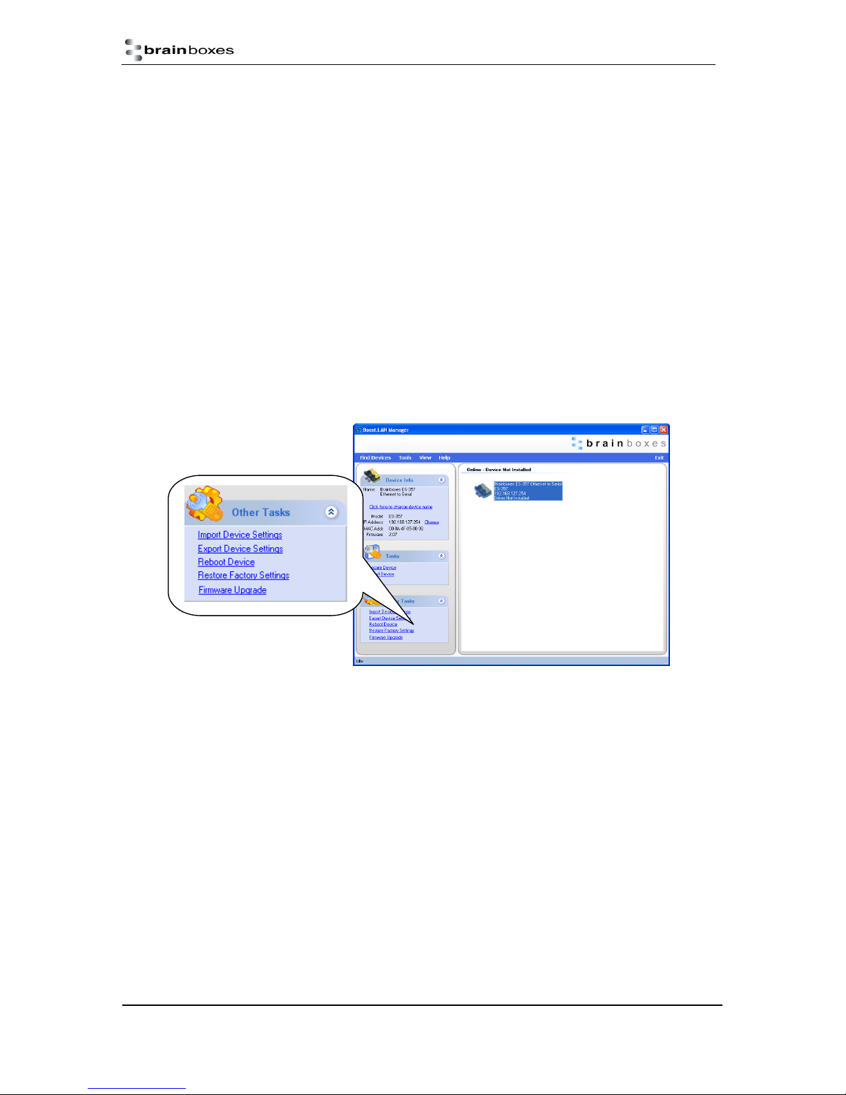
1) Open Boost.LAN Manager
2) Find and select your installed ES Device.
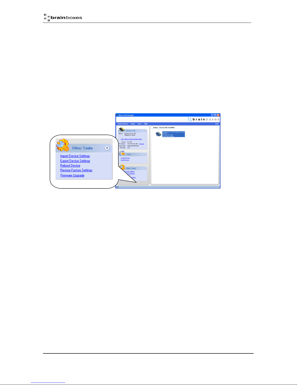
3) On the left hand panel of the window, scroll down to the “Other Tasks” section.
ES Range Product Manual
© Copyright Brainboxes Limited 2013
Version 2.9
Page 47 of 66
Page 48
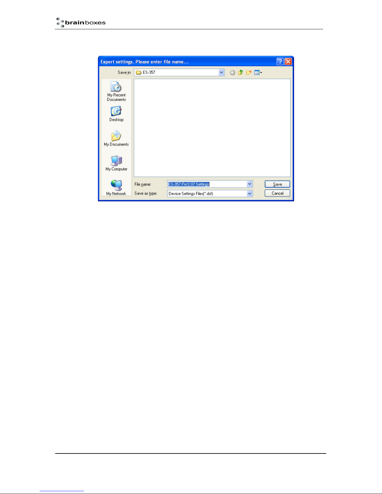
4) Select “Export Settings”
5) Browse to a location where you wish to save the settings file to.
6) Enter a file name in the “File name” box. E.g. “Device Model, Firmware Version XX“ etc)
7) Press Save.
Importing Device Settings
1) Open Boost.LAN Manager
2) Find and select your installed ES Device
3) On the left hand panel of the window, scroll down to the “Other Tasks” section
4) Select “Import Settings”
ES Range Product Manual
© Copyright Brainboxes Limited 2013
Version 2.9
Page 48 of 66
Page 49
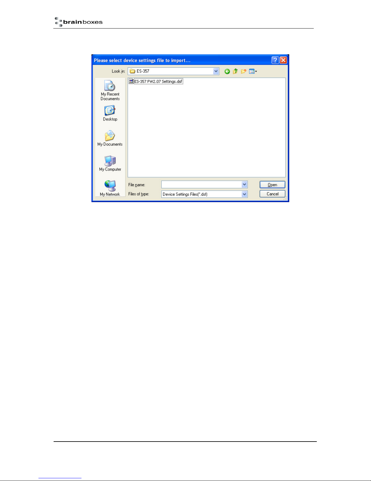
5) Browse to the location where you saved the settings file.
6) Select the file and press Open
7) The device will then import the settings.
ES Range Product Manual
© Copyright Brainboxes Limited 2013
Version 2.9
Page 49 of 66
Page 50
13. Rebooting Device
We strongly recommend that you check that the device is NOT in operation before doing this to
prevent data loss.
Rebooting in Boost.LAN Manager
If for any reason you wish to reboot your device, whilst still retaining the existing settings:
1) Open Boost.LAN Manager
2) Find and select the ES device you wish to reboot.
3) On the left hand panel of the window, scroll down to the “Other Tasks” section
4) Select “Reboot Device”
5) The device will beep to indicate that it has restarted. Any connections you may have had to
the COM port may need to be reopened.
Manual Reboot
1) Press the reset button once and after 5 seconds the device will beep.
2) The device will restart and any connections you have had to the COM ports will need to be
re-established.
ES Range Product Manual
© Copyright Brainboxes Limited 2013
Version 2.9
Page 50 of 66
Page 51
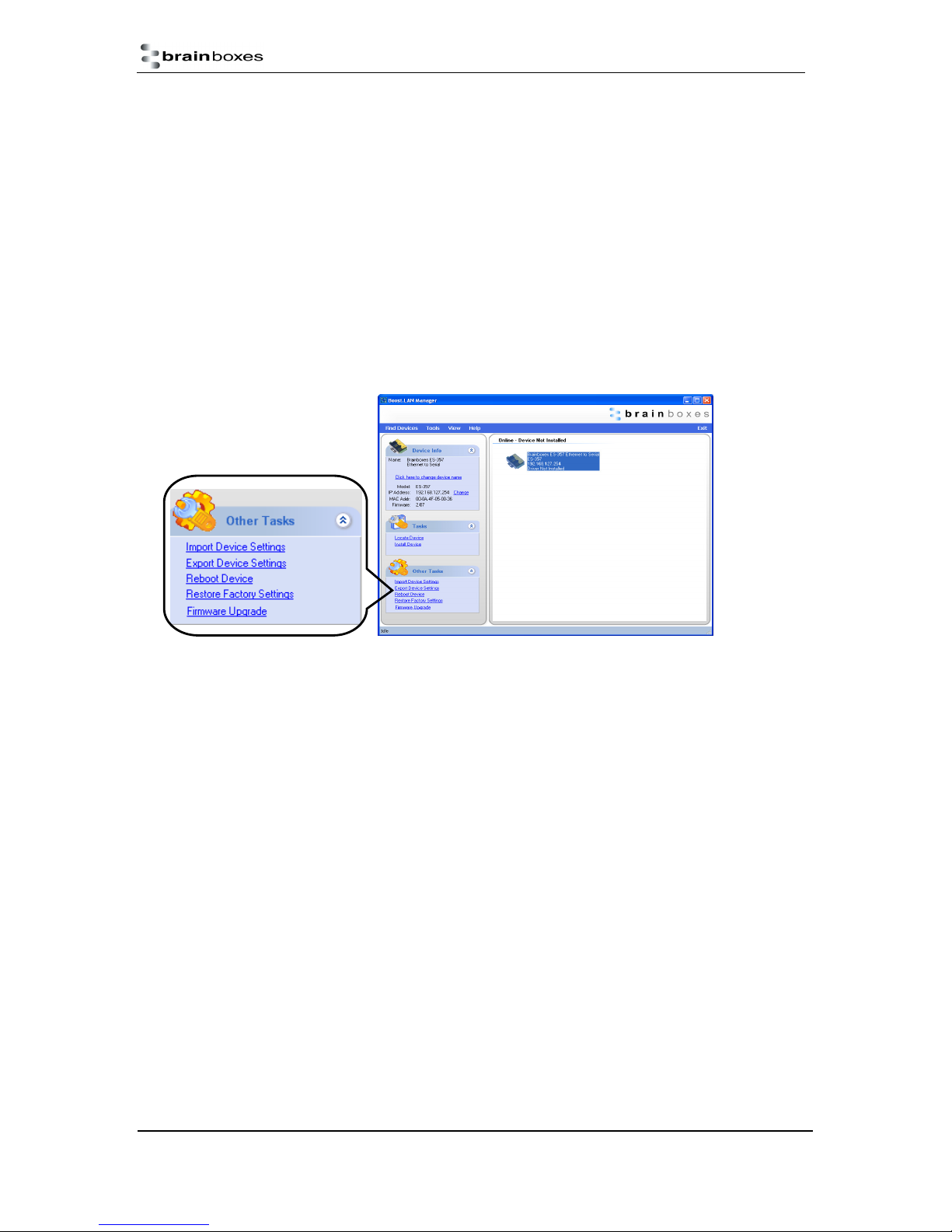
14. Restoring to Factory Default
Restoring back to Factory Default Settings
We strongly recommend that you check that the device is NOT in operation before doing this to
prevent data loss.
If for any reason you wish to restore the ES device back to factory default settings:
1) Open Boost.LAN Manager
2) Find and select the ES device.
3) On the left hand side of the window, scroll down to the “Other Tasks” section
4) Select “Restore Factory Settings”
5) The ES device will beep to indicate that the device has been restored back to factory settings.
See Section 3 for factory default settings.
Manual Hard Restore
1) Press and hold the reset button on the ES device until it beeps.
2) Once the ES device has beeped, then you can release the reset button.
3) The device will then be restored to factory settings.
ES Range Product Manual
© Copyright Brainboxes Limited 2013
Version 2.9
Page 51 of 66
Page 52
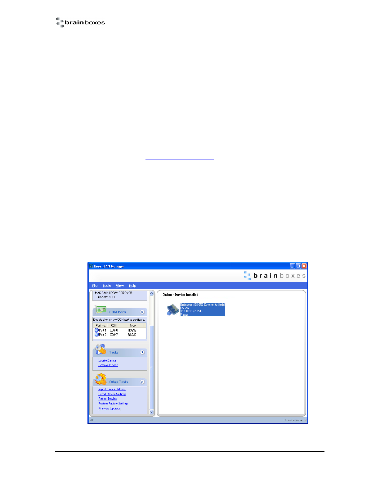
15. Firmware Upgrade
To upgrade your firmware to the latest release by Brainboxes follow the instructions below:
NB: If you have firmware 3.12 or older we recommend running the firmware upgrade with the ES
device connected directly into the PC using an Ethernet cable.
1) Open Boost.LAN Manager
2) Select your device from the Boost.LAN window.
3) Make a note of the current firmware version on the left hand panel.
4) Close Boost.LAN Manager.
5) Visit Brainboxes website, www.Brainboxes.com/faqs and locate the latest firmware version for
your device. Alternatively, contact Brainboxes Technical Support via
[email protected] and request the latest firmware version be sent to you.
6) If the firmware online or received by Brainboxes Technical Support is a later version,
download and save the file to a location you will remember
i. If the firmware is NOT a later version, do not proceed with the upgrade.
7) Open the Boost.LAN Manager
8) Select your device
9) Go to the left hand panel and select “Firmware Upgrade”
ES Range Product Manual
© Copyright Brainboxes Limited 2013
Version 2.9
Page 52 of 66
Page 53
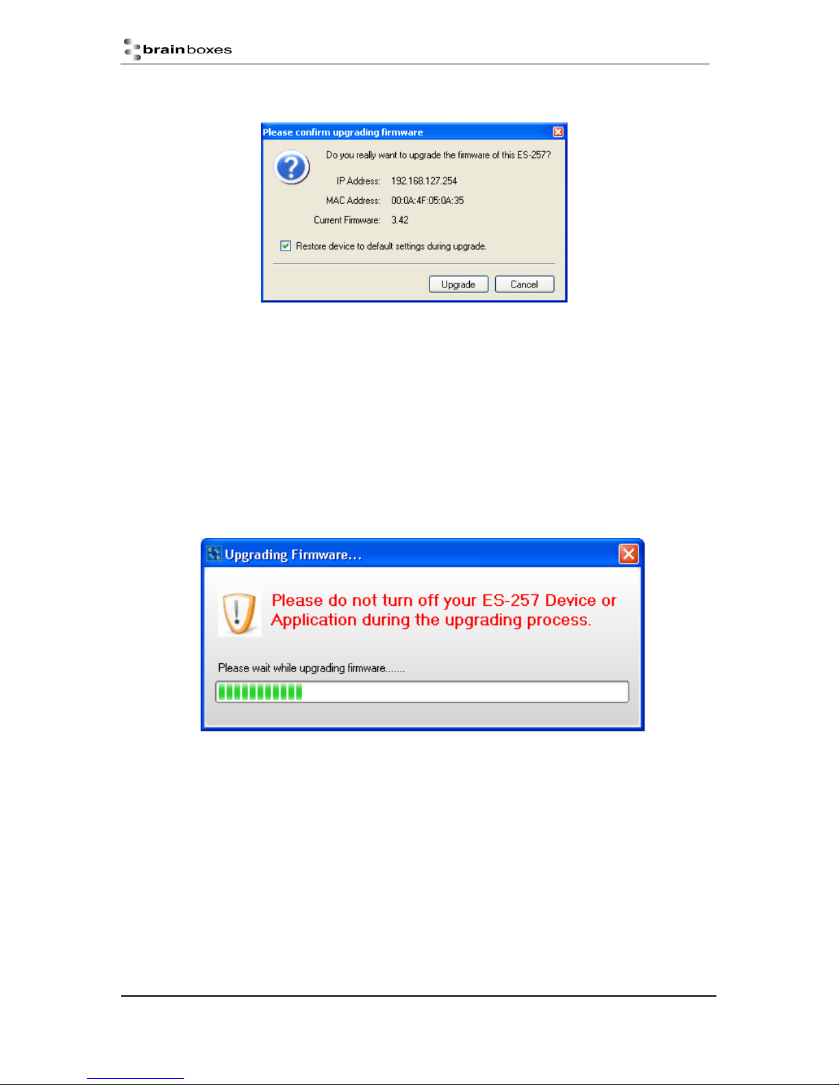
10) A message box will
appear asking you
to confirm you wish to
upgrade the firmware.
11) Press OK
12) Browse to the directory where you saved the latest firmware.
13) Select the firmware (the file extension will be .efw)
14) Press Open
15) Do not disconnect the ES Device from the network or power during the upgrade process.
16) Once the upgrade process is complete, select the device and check the firmware version
shown in the left hand panel is now the later version.
ES Range Product Manual
© Copyright Brainboxes Limited 2013
Version 2.9
Page 53 of 66
Page 54
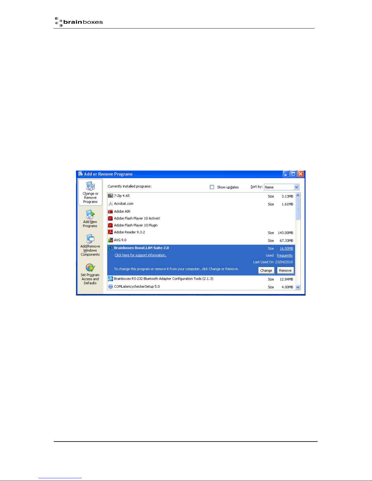
16. Uninstallation
It is possible to uninstall individual ES devices from your computer or remove the complete Boost.LAN
Suite.
Complete Boost.LAN Suite Uninstallation.
This will remove all Brainboxes Boost.LAN related software, including the Boost.LAN Manager and
device driver.
This can be done at any time, with or without the device connected. The uninstallation steps below
are applicable to all devices in the ES Ethernet to Serial range.
1) Open Control Panel, and then open “Add or Remove Programs”
2) Click on the “Brainboxes Boost.LAN Device Driver Suite” and then click Remove
3) The Brainboxes Boost.LAN Suite will then be uninstalled.
Individual Device Uninstallation
This can be done at any time, with or without the device connected. The un-installation steps below
are applicable to all devices in the ES Ethernet to Serial range.
1) Open the Boost.LAN Manager
2) Find and select your ES device
3) Click “Remove Device” on the left hand panel
4) Once the device is removed, it will be listed in the “Online – Driver not installed” section.
When finished, you may disconnect your ES device. To reinstall, simply follow the installation
instructions as in Section 4
ES Range Product Manual
© Copyright Brainboxes Limited 2013
Version 2.9
Page 54 of 66
Page 55

Question
Description
Solution
17. Troubleshooting and Testing
The most common problems and frequently asked questions for the ES range of devices are listed in
the table below along with descriptions and suggestions for corrective actions.
Problems installing
Boost.LAN Device
Manager
Can’t find ES
device in
Boost.LAN Device
Manager
Problems installing
Boost.LAN COM
port driver
Code 10 Error in
Device Manager
Boost.LAN installation wizard has
not completed or shows an error
When the ‘Find Devices’ button is
clicked the device isn’t displayed in
Boost.LAN manager.
Can’t install the ES device COM
ports.
Device Manager reports “This
device cannot start. (Code 10)”
Restart the PC and try installing
Boost.LAN again.
Check if there is an updated driver
package online at
http://www.Brainboxes.com
Check that the device is correctly
powered up and plugged into the
network.
Check the Ethernet and status LED
behaviour (see Section 3 Hardware
Features)
Ensure Brainboxes Boost.LAN Suite is
set as an exception in Windows Firewall
if it is enabled, and any other custom
firewall that you have installed.
If you have a proxy server installed
check Boost.LAN is on the exceptions
list.
If you are connecting through a router
check that port forwarding is enabled on
the router.
If device manager shows error
messages for the Ethernet to serial
device and ports (errors are indicated by
a yellow exclamation mark), it is
recommended to uninstall and re-install.
If the problem is still present after trying
the above, try another computer to
narrow down the problem.
In the device Properties dialog box, click
the Driver tab, and then click Update
Driver to start the Hardware Update
Wizard. Follow the instructions to update
the driver.
Cannot open COM
port
ES Range Product Manual
There is an error when trying to
open the COM port.
Install the latest drivers found on our
website.
Try installing the COM port on a different
PC.
Check the Ethernet cable is plugged in
to the device.
Check the ES device is correctly
installed, and the ports appear in Device
Manager without any errors (Errors are
Version 2.9
© Copyright Brainboxes Limited 2013
Page 55 of 66
Page 56

Communication
Problems
Can’t access ES
configuration
webpage
Problems transmitting or receiving
data through the port.
When you try to access the
webpage by typing the IP address
into the address bar of your web
browser, the page cannot be
indicated by a yellow exclamation mark.)
Make sure that the port you are trying to
open is not being blocked by a firewall
that may be installed.
If you are using a hub/switch or another
device between the network server and
ES device, check that it’s powered and
working correctly.
If you are using the ES device in Static
IP mode, check that its IP address is in
the same sub-net as the server.
Check that there are no IP address
conflicts on the network.
If you are using the RS-422/485 in half
duplex mode, make sure it is set for half
duplex communication in the software.
Check if there is an updated firmware or
software driver package for your ES
device by contacting Brainboxes
Technical Support with your existing
software version.
Check the status LED behaviour. (See
Section 3. Hardware Features)
If the status LED is showing a problem
perform a power cycle, and if there is
still a problem restore the factory
settings. (See Section 13)
Make sure that you have access to the
device which you are trying to open the
COM port of.
If the problem is still present after trying
the above, try a different network card if
possible.
Check the status LED behaviour. (See
Section 3. Hardware Features)
If the status LED is showing a problem
perform a power cycle, and if there is
still a problem restore the factory
settings. (See Section 13)
Perform a loopback: The loopback test
will verify that your ES device is able to
Transmit and Receive data. The transmit
and receive lines are connected together
so any data sent is received on the
same port. Details of loopback tests can
be found on our website.
http://www.Brainboxes.com/
Check the status and Ethernet lights on
the device show that the device is
connected to the network and ready.
(See section 3 Hardware Features)
ES Range Product Manual
© Copyright Brainboxes Limited 2013
Version 2.9
Page 56 of 66
Page 57

displayed. Check that the IP address is the correct
one. If you are on a private network the
default IP address is 192.168.127.254.
If you have a proxy server installed
check IP address of the device is on the
exceptions list.
Error page loads
when trying to load
web Configuration
page
When loading the web configuration
page, the Brainboxes web page
loads with an error.
Check that you have user or admin
access to the device that you are trying
to load. If the security settings are on
you will need your MAC address added
to the access list.
To clear the security settings you will
need to hard reset the device by holding
the reset button on the device for 10
seconds, until the device beeps twice.
You will then have access to all the web
configuration pages.
Problem Upgrading
Firmware
The upgrade process does not start
or continues to restart without
completing successfully
We recommend using a direct Ethernet
to PC connection when upgrading the
firmware of your ES device. Using this
private network means the upgrade will
run smoother and quicker because there
is no other traffic on the network.
Old hardware /
equipment
Users often have old hard or
equipment which they think may not
work with the ES products.
Brainboxes ES products use the
Brainboxes 16C950+ UART which can
meet the most stringent demands. It has
very tight timing characteristics
implemented in the hardware. It
supports between 60 baud and
1,000,000 baud (1Mb). Also supports
any custom baud rate as standard. It
has a 2 kilobyte FIFO on Rx and Tx.
Grounding Grounding the device for a return
path for induced common mode
noise and receiver current.
Brainboxes products have a Signal
Ground connection on each serial
port. Connect the Ground wire to this;
optionally add a 120Ω 1Watt resistor in
series at one end of the
Bus.
Should the problem still persist with your ES device please contact [email protected]
with:
o Your Loopback test result
o IP address
o Static or DHCP setting
o COM Setting required (baud rate, data bits, parity, stop bits and handshaking)
o Firmware and Driver version.
ES Range Product Manual
© Copyright Brainboxes Limited 2013
Version 2.9
Page 57 of 66
Page 58

18. Linux support for ES devices
The Ethernet2Serial can work in Linux but the drivers are not compatible, which means you cannot
use Boost.LAN. To use the device, you would have to open the port using the IP address. You can
configure the settings etc using the device webpage (by entering its IP address into your search bar).
It is possible to communicate with the ES range of devices from Linux for both configuration and
communicating with attached devices using standard serial port applications. This is achieved by
using the Cyclades Serial Client application.
NB the Cyclades Serial Client application is open source software, which is not owned or distributed
by Brainboxes. Brainboxes cannot be held responsible for any loss or damage incurred from using
this software.
Configuring the ES device from Linux
• To configure the device, you will need to know the device’s IP address. You should be able to
get this information from your network administrator. If this is not possible, you can search for
the ES device from a Linux machine using upnp_search.pl. This can be found on the CD in
the directory Product Support/Utilities/Linux Tools and requires Perl to be installed along
with the Net::UPnP Perl module.
• Configuration of all the options on the device can be done using the Web page interface. This
can be done from any OS, using any modern browser (e.g Mozilla Firefox, Konqueror, Opera,
etc) See Section 10.
• Note: The Cyclades Serial Client will not be able to track changes in the IP address of an ES
product on the network. It is for this reason that we recommend setting the device to a static
IP address on the ES device when used with Linux.
Using Cyclades Serial Client to communicate with ES device ports
• The Cyclades serial client can be downloaded as an rpm, or can be installed from the
standard package repositories of many popular flavours of Linux, including Debian and
Ubuntu.
• After installation, the correct details for the Brainboxes ES ports will need to be added to the
/etc/cyclades-devices file. You will require one configuration line for each port, which contains
the following details in a colon separated format;
o devname the device node in /dev, e.g. /dev/ttyS0
o rastype this is just set to Brainboxes
o rasname the IP address of the ES device on your network
o physport port number on the device
o type communications protocol. Set to rfc2217
o options further device specific options –p 9000 –d 0
ES Range Product Manual
© Copyright Brainboxes Limited 2013
Version 2.9
Page 58 of 66
Page 59

Example lines for and ES-357 device are given below;
/dev/ttyS8:Brainboxes:192.168.0.223:1:rfc2217:-p 9000 -d 0
/dev/ttyS9:Brainboxes:192.168.0.223:2:rfc2217:-p 9000 -d 0
See man cyclades-devices and also text within /etc/cyclades-devices for more information.
• After the ES product port information has been added to the /etc/cyclades-devices file, the
cyclades device server should be started and stopped using the commands (as root);
o cyclades-serial-client start
o cyclades-serial-client stop
These should be integrated into your rc.d scripts so that the ES devices are initiated and
stopped on your system start up and halt.
ES Range Product Manual
© Copyright Brainboxes Limited 2013
Version 2.9
Page 59 of 66
Page 60

19. Lifetime Warranty and Support
To receive the lifetime Warranty, you need to register your product with us
using our online form.
NB: this must be done within 28 days of Purchase.
Lifetime Warranty Sign up
* Terms and Conditions are available online. Standard warranty period is 3 years if a product is not
registered.
Since 1983, Brainboxes have designed, tested and manufactured our
products all under one Roof. One of our greatest strengths is in after sales
service. Technical Support is provided by members of our Test Team, who
know our products inside out and have direct access to the chip and board
designers as well as the technicians who built and tested your product.
If you have any issues, questions or suggestions about our Products and
Services, then please contact us.
Technical Support is free*. As long as you have a Brainboxes Product we will
be happy to help, even if it’s discontinued or out of warranty. Excellent Customer Service, just as it
should be.
For the quickest solution to your issue, if you email us, please include as much detail of your setup
and the fault you are experiencing.
* Standard rate call charges for phone support apply.
Email
Technical Support: [email protected]
Sales Enquiries: [email protected]
Telephone
You can speak to Brainboxes Support or Sales teams direct,
Monday – Friday, 9am to 5pm (UK time)
Tel: +44 (0)151 220 2500
ES Range Product Manual
© Copyright Brainboxes Limited 2013
Version 2.9
Page 60 of 66
Page 61
!
20. Technical Specifications
Device specification
Network connection
10Base-T or 100Base-TX Ethernet connection
Standard 8P8C (“RJ45”) socket connector
TCP/IP protocol stack
DHCP or static IP address
Automatic transmit/receive crossover detection
1500V isolation
RS-232 Serial Port
Baud rates up to 1M Baud
5, 6, 7 or 8 data bits
1 or 2 stop bits
Odd, even, mark, space or no parity bit
Line-break generation and detection
RTS/CTS, DTR/DSR or XON/XOFF flow control option (terminal block models do not support
DTR/DSR)
ESD protection to 15kV human body model
Can be connected to as a Windows COM port, as a raw TCP socket, or using the RFC2217 standard
Serial cable length: 3m maximum (EU only)
RS-422/485 Serial Port
Baud rates up to 1M Baud
5, 6, 7 or 8 data bits
1 or 2 stop bits
Odd, even, mark, space or no parity bit
Line-break generation and detection
RTS/CTS and XON/XOFF flow control option (terminal block models do not support RTS/CTS)
Automatic switching between transmit and receive states in half-duplex mode
3-wire half-duplex RS-422/485 link mode
Built-in termination and biasing at receiver inputs
Can be connected to as a Windows COM port, as a raw TCP socket, or using the RFC2217 standard
Serial cable length: 3m maximum (EU only)
Power
Wide-range 5-30V DC power input (1.0W typical, 1.8W maximum)
Reverse voltage protected
ESD and surge protected
Earthing connection point
ES Device Recommended Power Supply
ES-246 Shipped as standard with PW-844 (UK) / PW-811 (EU) (5V, 550mA)
ES-257 Shipped as standard with PW-844 (UK) / PW-811 (EU) (5V, 550mA)
ES-313 Shipped as standard with PW-844 (UK) PW-811 (EU) (5V, 550mA)
ES-320 Shipped as standard with PW-844 (UK) / PW-811 (EU) (5V, 550mA)
ES-357 Optional PW-644 (UK) / PW-611 (EU) (5V, 550mA)
ES-020 Optional PW-644 (UK) / PW-611 (EU) (5V, 550mA)
Caution - Do not attempt to operate this product with
any other power supply/rating than that specified.
ES Range Product Manual
© Copyright Brainboxes Limited 2013
Version 2.9
Page 61 of 66
Page 62
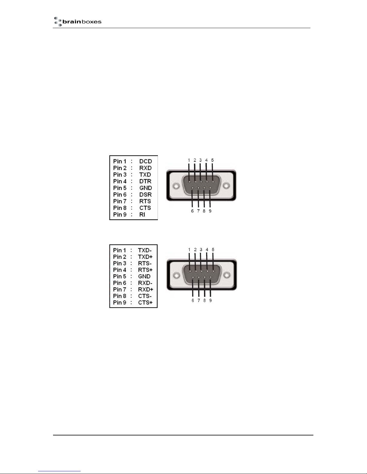
LED indicators
Indicators for the network and serial ports show when a connection is open and when data is being
transferred.
Three-colour status LED provides additional information on the status of the device.
For more information see LED information in Section 3. Hardware
Physical
Plastic enclosure
Mounting flanges for wall-mounting or attachment of optional DIN-rail mounting kit
DB9 Connector Pin-out (dependent on ES Model)
The ES devices which have DB9 connectors have the following set of signals.
i. RS-232 Port:
ii. RS-422/485 Port
For RS-422 FULL Duplex Communications, please note the pin outs above.
To achieve RS-485 Half Duplex Communications, using two wires for communication, Pins 1 and 6,
2 and 7 must be physically shorted.
Once your wiring is setup, you will also need to set the device to FULL or HALF Duplex mode in the
software. For further details, see Section 6
ES Range Product Manual
© Copyright Brainboxes Limited 2013
Version 2.9
Page 62 of 66
Page 63
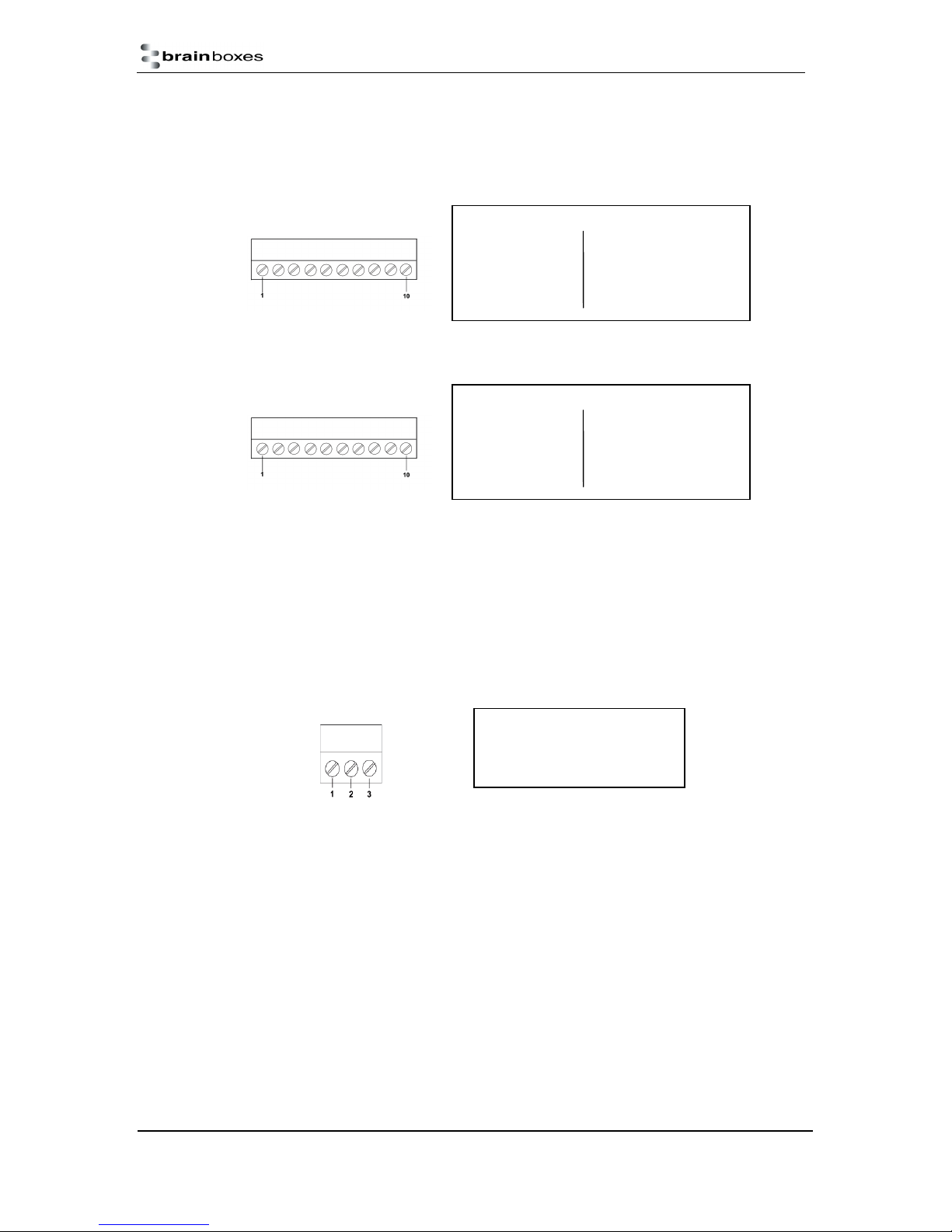
Terminal Block Connector Pin out (dependent on ES Model)
For ES devices with terminal block connectors have the signals detailed below.
i. RS-232 & RS-422/485 Port (e.g. ES-357)
Port screw terminal pin outs
ii. RS-232 1 Port (e.g. ES-020)
Port screw terminal pin outs
For RS-422 FULL Duplex Communications, please note the pin outs above.
To achieve RS-485 Half Duplex Communications on a terminal block, using two wires for
communication, you need to use the “Data” pins marked with D+/D-. E.g. for the ES-357 this would be
Pin 8 and Pin 9.
Once your wiring is setup, you will also need to set the device to FULL or HALF Duplex mode in the
software. For further details, see Section 9
iii. Power Terminal Block
Port screw terminal pin outs
RS-232 RS-422/485
Pin 1 TxD Pin 6 TxD+
Pin 2 RxD Pin 7 TxDPin 3 RTS Pin 8 RxD+/D+
Pin 4 CTS Pin 9 RxD-/DPin 5 GND Pin 10 GND
RS-232
Pin 1 TxD Pin 6 DTR
Pin 2 RxD Pin 7 DSR
Pin 3 RTS Pin 8 DCD
Pin 4 CTS Pin 9 RI
Pin 5 GND Pin 10 GND
Pin 1 V+ Power Supply +
Pin 2 V- Power Supply Pin 3 Earth/Chassis Ground
Storage and Operating Environment Guidelines
Storage
Temperature: -10oC to +70oC
Humidity: 8% to 95% non-condensing
Operational
Temperature: 0oC to +50oC
Humidity: 20% to 75% non-condensing
ES Range Product Manual
© Copyright Brainboxes Limited 2013
Version 2.9
Page 63 of 66
Page 64

21. Regulatory Approvals / Compliance
For up to date details of global certifications, please check the product datasheet on the Brainboxes
website.
Company Accreditation
Brainboxes achieved accreditation to the ISO14001 environmental standard early 2008. This globally
recognised standard ensures Brainboxes can demonstrate effective management of all its
environmental impacts, together with a process of continuous improvement.
Brainboxes have also been an ISO9001 registered company since 1994. This has ensured that
Brainboxes products, right from design to manufacture, have been produced to the highest standards.
We operate this Quality Management System throughout the company, and it is subject to regular
external surveillance visits.
Brainboxes have always been aware of the need to continually review company processes and has
been working with National Quality Assurance (www.nqa.com) since 1994, helping the company to
create and maintain internationally recognised accreditation standards.
Linked with our Lean and Six Sigma techniques, we believe we have the most reliable products on
the market, and to back this up we are offering a Lifetime Warranty* on all our Serial Products.
Europe – EU Declaration of Conformity
The ES Ethernet to serial devices conform to the protection requirements of European Council
Directive 2004/108/EC
The products are designed to meet the standards detailed below. The Declaration of Conformity and
supporting Technical Construction File is available by request from Brainboxes.
EN 55022:1998 A2:2003
Class A
EN 55024:1998 A2:2003
Class A
Information technology equipment — Radio disturbance
characteristics — Limits and methods of measurement
Information technology equipment — Immunity characteristics —
Limits and methods of measurement
This product is a Low Voltage Device, designed and manufactured to EN60950 safety standard. On
no account should the power supply be opened or modified in any way; if damaged, the power supply
must be disposed of, observing local arrangements for recycling.
The ES range has been made to comply with the latest EMC standards.
WEEE Directive (Waste Electrical and Electronic Equipment)
The WEEE Directive 2004/96/EC came into force, in the UK, at the beginning of 2007.
Customer Responsibilities
ES Range Product Manual
© Copyright Brainboxes Limited 2013
Version 2.9
Page 64 of 66
Page 65

At the end of life, this product must be disposed of in accordance with WEEE regulations.
This can be done through your local civic amenities site, an approved treatment facility or
alternatively through a relevant compliance scheme.
Brainboxes’ Responsibilities
Brainboxes’ has a legal responsibility, as producer, to provide a free of charge collection
service to our customers for our obligated WEEE.
Brainboxes is defined as a producer under the WEEE Regulations because we sell own
brand Electrical & Electronic Equipment (EEE) in the UK. Our WEEE Producer Registration
Number is WEE/AH0004XR. For more information, click here.
For details of our WEEE recovery service options, please see our Website, or email us at:
RoHS Compliance
All Brainboxes Serial and Bluetooth products are fully RoHS compliant.
Brainboxes identified at an early stage the importance of rapid compliance to
RoHS guidelines and established a project team to actively manage the
transition. The initial step in the process was to use our close relationships with
suppliers to ensure early access to RoHS compliant components for all of our
Bluetooth and Serial Products. In addition, the project team worked to ensure
that our manufacturing processes meet all RoHS requirements well in advance of
the deadline.
To verify supplier declarations on RoHS compliancy, we have also sent fully built
products to an external test house for X-Ray Fluorescence testing on
components, using the Fischerscope X Ray system XDAL. This technique is capable of determining
percentages of different elements and is accurate to 0.1% Wt.
RoHS Compliant Brainboxes products have been available since January 2005.
What is the RoHS Directive?
The RoHS directive (2002/95/EC the Restriction of the use of certain Hazardous Substances in
Electrical and Electronic Equipment) prohibits the sale of electrical and electronic equipment
containing hazardous substances. A list of these hazardous substances includes lead, cadmium,
mercury, hexavalent chromium, polybrominated biphenyls and polybrominated diphenylethers. RoHS
affects each and every electronics manufacturer, directly or indirectly, regardless of geographical
location or the equipment they produce.
ES Range Product Manual
© Copyright Brainboxes Limited 2013
Version 2.9
Page 65 of 66
Page 66

22. Copyright
Copyright © Brainboxes Ltd
All rights reserved. No part of this hardware, circuitry or manual may be duplicated, copied,
transmitted or reproduced in any way without the prior consent of the Manufacturer
23. Version History
Version Date Author Checked
Comments
By
0.1 06.07.2009 AH PA,DA
0.2 31.07.09 AH With feedback from Sales & R&D,
Name change to Boost.LAN
0.3 01.08.09 AH
0.4 01.09.09 DA
AW
PG, CP Added Security support
AH, MA Added Linux support
Screenshots updated
1.0 10.09.09 AH First Official Release (with ES-357)
1.5 11.09.09 BH AH Added Windows 7, Device tunnelling, Proxy
Server, Remote access and other products in
range.
Manual applies to firmware version 3.0 and
above.
2.0 06.07.10 BH MA, AH Added Transmission interval and ES-313 and
ES-320 duplex information.
2.1 28/7/10 BH Updated FAQ’s and added info about firmware
2.4 29/9/11 BH Added ES-701 & ES-279 information.
2.8 21/5/12 BH Added ES-020 information
2.9 08/03/13 CL Added RS-422/485 information and added to
2.9 25/06/13 CL Added Windows 8 procedures
ES Range Product Manual
upgrade changes.
troubleshooting
Version 2.9
© Copyright Brainboxes Limited 2013
Page 66 of 66
 Loading...