

Page 1
Quick Start Guide
for Brainboxes Ethernet to Serial Range
ES-246, ES-257, ES-313, ES-320, ES-357
ES-701, ES-279, ES-346 & ES-842
Page 2

1. Box Contents Check List 2
2. Hardware 3
3. Network IP Addressing 4
4. Connecting your ES Device 5
5. Installing your ES Device on Windows 6
6. Configuring your ES Device 11
6.1. Finding your COM port. 11
6.2. Advanced Configuration: Changing the IP address 11
6.3. Advanced Configuration: Changing the COM label 13
7. Default Settings 14
8. Pin outs 15
8.1. Serial DB9 Pin outs 15
8.2. Serial Terminal Block Pin outs 15
8.3. Power Terminal Block Pin outs
9. LED information 16
For more information, please refer to Product Manual on CD
Information on Product Accreditations, Safety, and correct disposal of this product can be found on the Product CD
1
Contents
Windows is a mark of Microsoft, the other marks belong to their respective owners. Brainboxes Limited. ES-QSG V2
Page 3
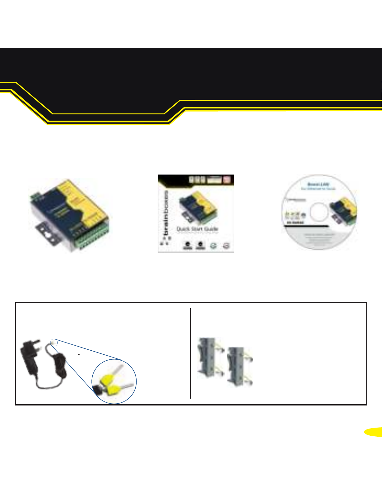
1. Box Contents Check List - ES-357
NB: Images below show an ES-357 1x RS232, 1x422/485 as an example. The same steps can be applied to all other products in the ES Ethernet to Serial range
Ethernet to Serial
Device
Quick Start Guide
Product CD
Thank you for purchasing Brainboxes Ethernet to Serial product. This quick start guide will
help you set up your ES device so that you can begin experiencing the benefits of Ethernet
to Serial technology.
2
Optional Accessory Items
PW-644 (UK) / PW-611 (EU)
- ES-357 - 1xRS232+1xRS422/485
MK-048
- ES-246 - 1xRS232
- ES-257 - 2xRS232
- ES-320 - 1xRS422/485
- ES-313 - 2xRS422/485
- ES-357 - 1xRS232+1xRS422/485
DIN Rail Kits
Power Supply
Page 4
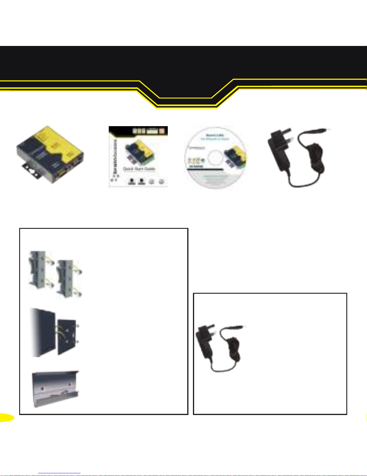
1. Box Content - All Excluding ES-357
3
Power Supply
PW-844 (UK) / PW-811 (EU)
- Output:5V CD 1.0A (5W)
PW-544 (UK) / PW-511 (EU)
- Output: 5V DC 3.0A (15W)
Ethernet to Serial
Device
Quick Start Guide
Product CD
DIN Rail Kit Optional Accessory Items
MK-048
- ES-246 - 1xRS232
- ES-257 - 2xRS232
- ES-320 - 1xRS422/485
- ES-313 - 2xRS422/485
- ES-357 - 1xRS232+1xRS422/485
PW-844 (UK) / PW-811 (EU)
- ES-246 - 1xRS232
- ES-257 - 2xRS232
- ES-320 - 1xRS422/485
- ES-313 - 2xRS422/485
- ES-701 - 4xRS232
- ES-279 - 8xRS232
PW-544 (UK) / PW-511 (EU)
- ES-346 - 4xRS422/485
- ES-842 - 8xR422/485
Optional Accessory Items
Power Supply
MK-059
- ES-701 - 4xRS232
- ES-279 - 8xRS232
- ES-346 - 4xRS422/485
- ES-842 - 8xR422/485
MK-070
- ES-701 - 4xRS232
- ES-279 - 8xRS232
- ES-346 - 4xRS422/485
- ES-842 - 8xR422/485
Page 5
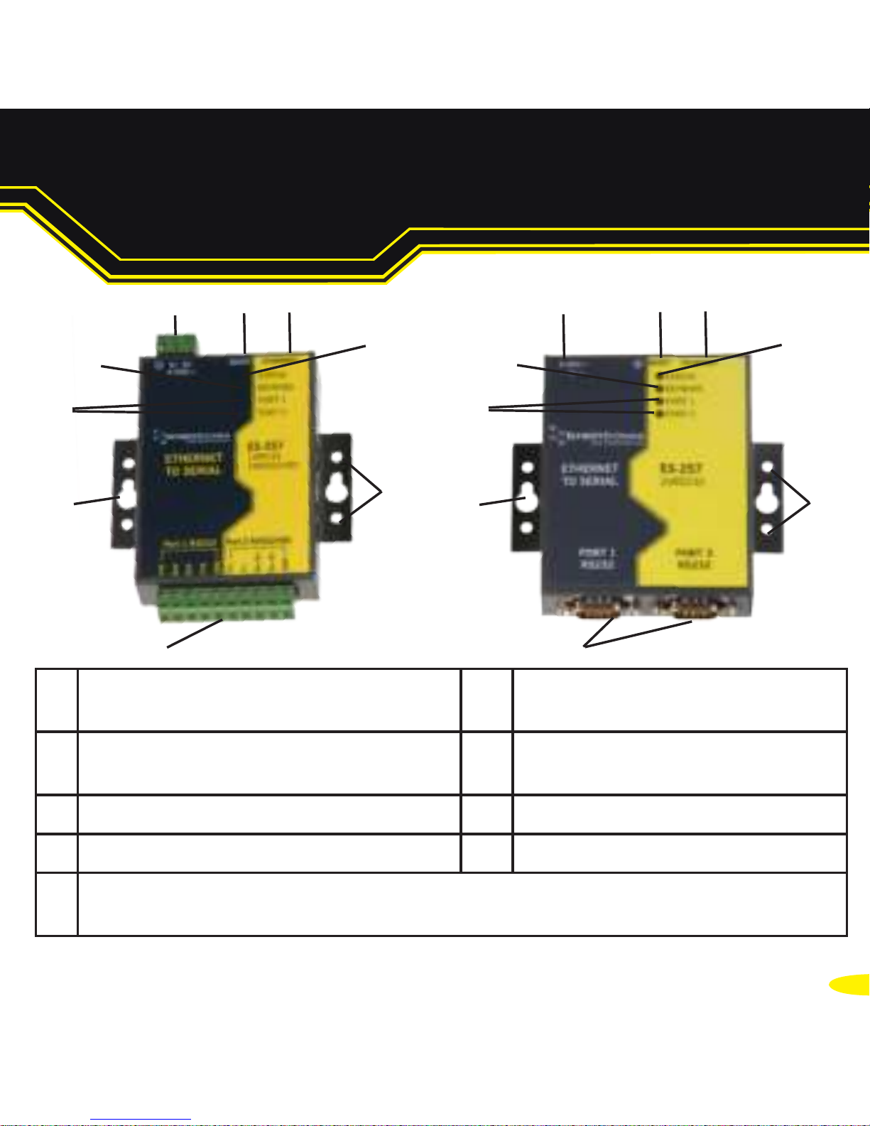
2. Hardware
4
1. 9 Pin D Serial Port or only on ES-357
screw terminal block connection
6. Reset button
(use unfolded paperclip
to press)
2. Wall mount screw hole 7. Ethernet port connection -
10BaseT / 100BaseTX
3. Serial Port(s) LED 8. Status LED
4. Ethernet LED 9. DIN Rail kit holes
5.
ES-357/ES-246/ES-257/ES-320 - Power Input 5-30V DC, 1.8W Max / 1.0W Typical
ES-313 -
Power Input 5-30V DC, 2.6W Max / 1.2W Typical
2
1
3
5 6
7
4
8
9
2
1
3
5 6
7
4
8
9
Page 6
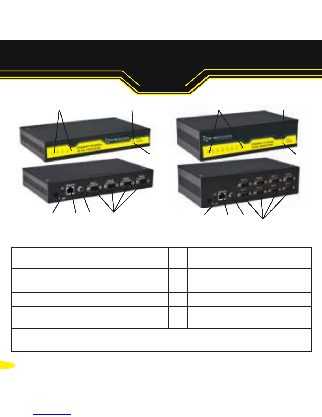
5
1. Serial Ports 6. Reset button
(use unfolded paperclip
to press)
2. Wall mount screw hole
(on underneath of box)
7. Ethernet port connection 10BaseT / 100BaseTX
3. Serial Port(s) LED 8. Status LED
4. Ethernet LED 9. DIN Rail kit holes
(on underneath of box)
5.
ES-357/ES-246/ES-257/ES-320 - Power Input 5-30V DC, 1.8W Max / 1.0W Typical
ES-313 -
Power Input 5-30V DC, 2.6W Max / 1.2W Typical
2. Hardware
1
1
3 38 8
6
6
7
7
5
5
9
9
Page 7

6
The ES device is shipped in “DHCP Mode".
l On connecting to the network, the device automatically checks if
it is connected to a DHCP Server. If this is the case, the DHCP server
will allocate an IP address automatically to the ES device.
lIf no DHCP Server is detected (e.g. you are connecting to a
Private network), the ES device will default to an IP address of
192.168.127.254 within 60 seconds. Please ensure the PC you’re
using for configuration can communicate with the 192.168.127.xxx
IP range.
3. Network IP Addressing
Page 8

7
1. Connect the ES device to your local network or a private network by
using a standard straight-through or crossover Ethernet cable and
plugging into the Ethernet port connection.
2. Connecting to Power
Connect the power adapter or a DC power line (5-30V)
to the ES power terminal block or jack connection
If using the Brainboxes PW-644 power supply ensure:
a. The wire marked “-“ is connected to V b. The wire marked “+” is connected to V+
*If using your own power supply please check input requirements on page 4 - Hardware
3. Confirm the device beeps as it is turned on.
4. When the Status LED starts blinking green (after 5-60
seconds), the device is ready to use.
5. Connect the serial cable from your serial device to the serial port on
the ES device. Refer to Section 8 of this Quick Start Guide for pin
outs.
Make a note of device MAC address (on side panel, 00-0a-4f-XX-XX-XX) as
you will need it to identify the device on your network later.
4. Connecting your ES Device
Page 9
8
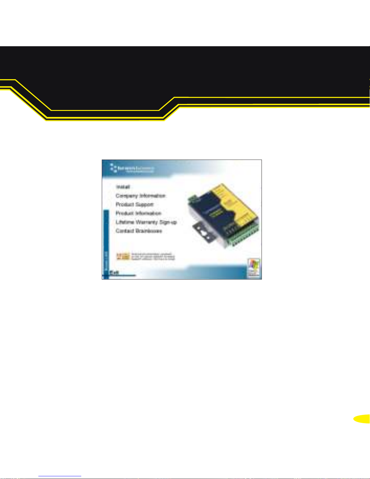
1. Insert the CD into your PC. This should launch the Boost.LAN
Navigation Page automatically.
Note: If the navigation page does not auto load, go to Start g My Computer g Right Click the
CD and select Explore. This will open the CD in Windows Explorer for browsing the contents of
the CD. Locate the “Setup.exe” program on the CD and double click to launch. Proceed to Step 3.
2. Click "Install" to launch the Boost.LAN Setup.exe
5. Installing your ES Device on Windows
Page 10
9
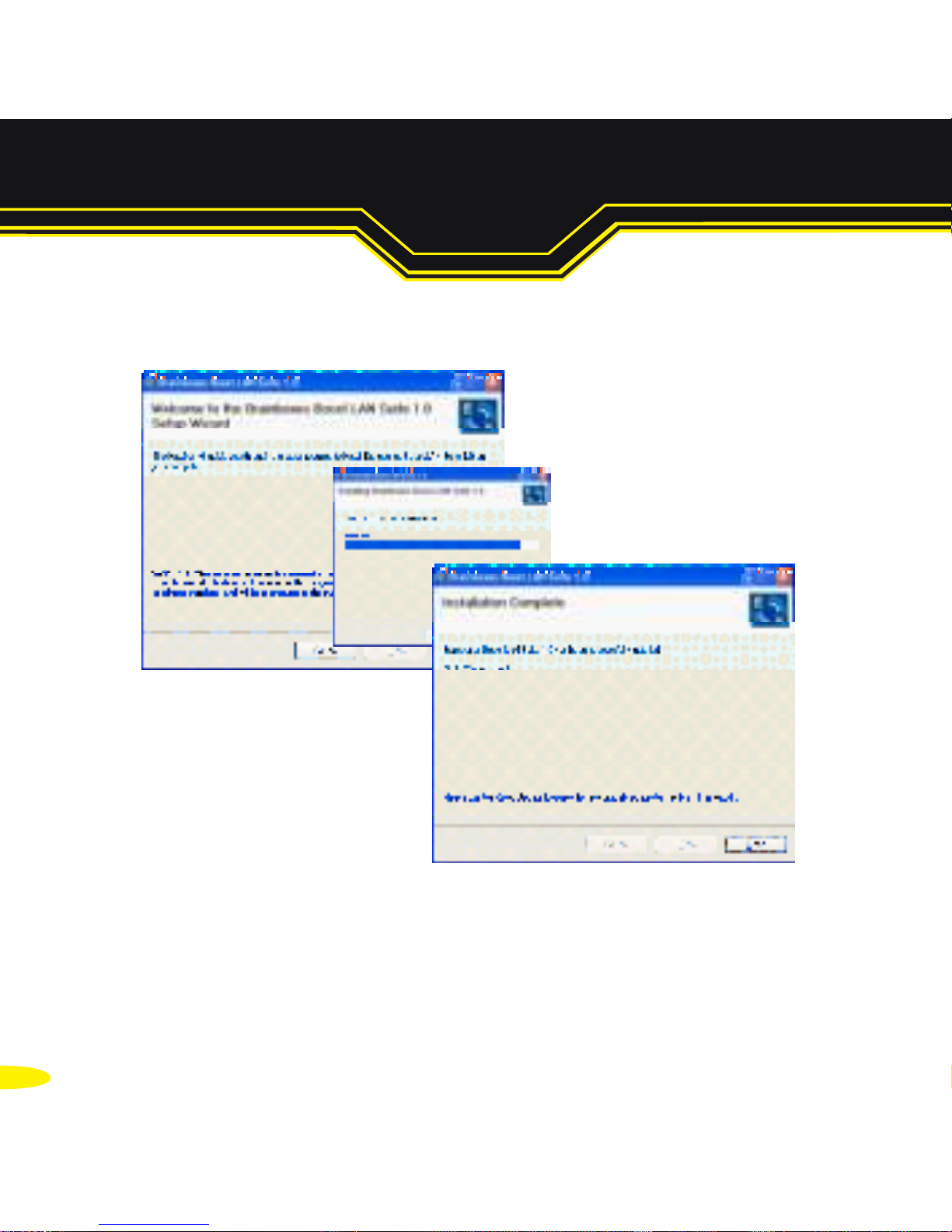
3. Follow the on screen instructions to install the Boost.LAN software.
Note: Boost.LAN software requires the Microsoft .NET framework to be
installed on your machine. If it is not already installed, the Setup.exe will
install it automatically. Please follow on screen instructions and reboot if
prompted to continue installation.
Page 11
10
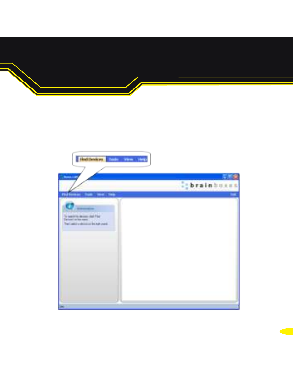
4. When installation is complete, you should see an icon labelled
Boost.LAN Manager on the desktop. Double click the link to
open the application
5. Click on the “Find Devices” link in the top left hand side of the
window.
5. Installing your ES Device Continued...
Page 12
11
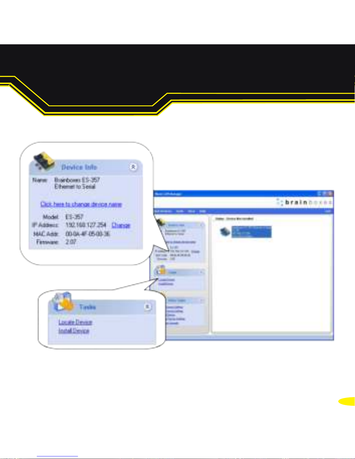
6. You can find your Brainboxes ES device by selecting a device and
matching it with the corresponding MAC address available on the
left hand panel (see opposite page).
7. Once found, select the device and scroll to the "Tasks" section on the
left hand panel
8. Click Install Device.
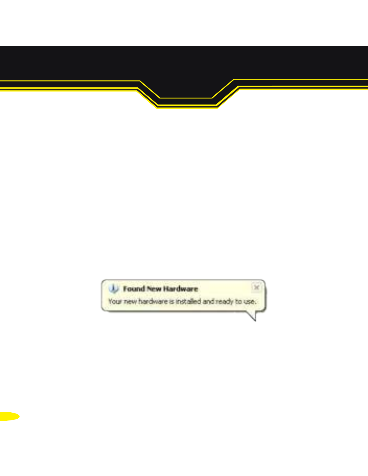
9. When the device is installed a pop up box will appear saying “Your
new hardware is installed and ready to use.”
Page 13
12
5. Installing your ES Device Continued...
Page 14
13
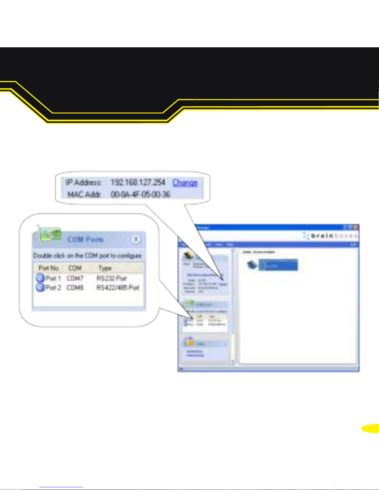
6.1 Finding your COM port
1. Open the Boost.LAN Manager and select your device
2.
Under the COM ports section, make a note of the COM port installed
and which COM port you will use to communicate to your serial
device (e.g. RS-232 or RS422/485 port)
3. Open your application and select the Brainboxes COM port.
4. Your ES device is now ready to be used with your application.
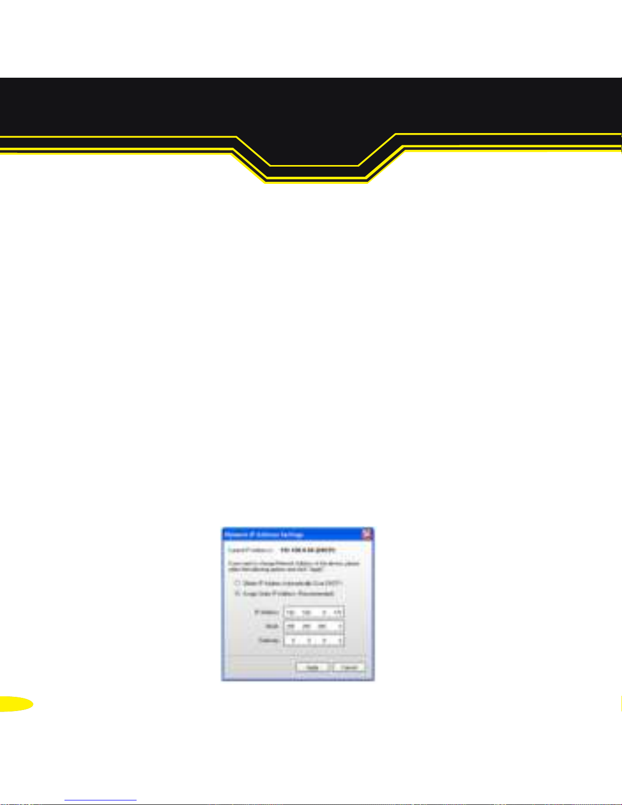
6.2 Advanced Configuration: Changing the IP address
1. Open the Boost.LAN Manager and select your device
2. Click the “Change” link in the Device Info panel (see next page).
3. Change the IP Addresses to your desired address.
6. Configuring your ES Device
Page 15
1414
6. Configuring your ES Device Continued...
Page 16
15
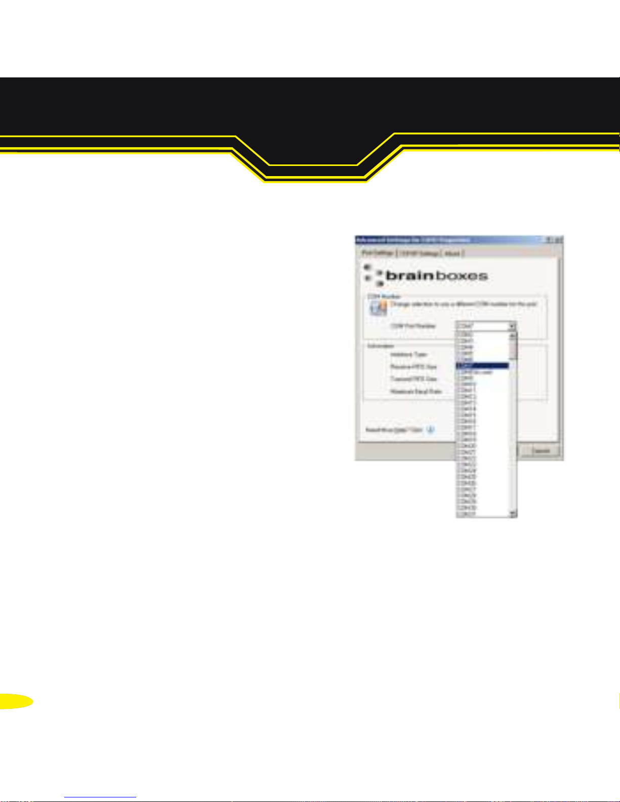
6.3. Advanced Configuration: Changing the COM label
1. Double click on the Port entry in the
Boost.LAN Manager.
2. Click on the 'Port Settings' tab
3. Click Advanced
4. A new COM Port label can be selected from the dropdown menu.
Click OK to set the new COM Label.
If the COM Port number is labelled “in use”, it is either currently
used by a COM Port present on the system, or is reserved for a
device which is not currently present. It is still possible to select this
COM number and force the change, if you are sure it is not required
by any other device.
Page 17
1416
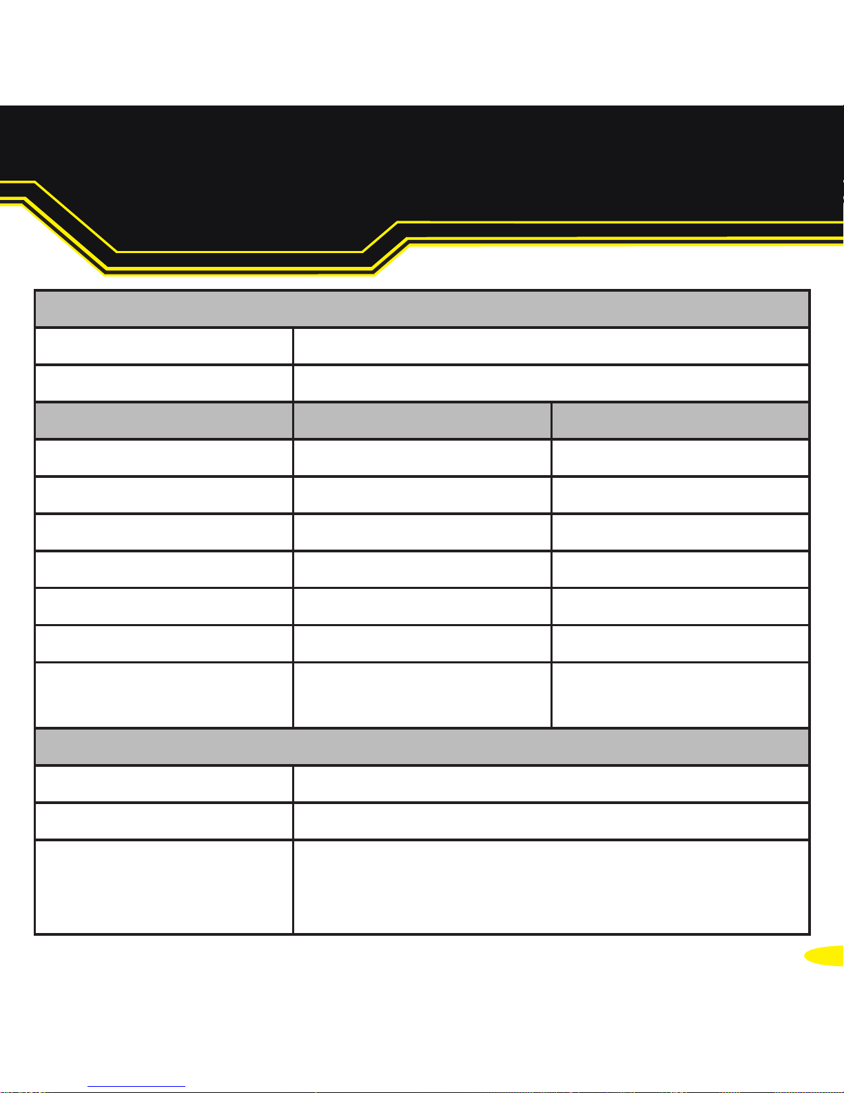
Network Settings
Device Network Address
DHCP mode
Web Server Port 80
Port Settings RS232 RS422/485
Baudrate 115200 115200
Databits 8 8
Stop Bits n n
Parity 1 1
Flow Control None None
Duplex Mode N/A Full Duplex
Protocol Settings Telnet + COM port
control Mode (Server)
Telnet + COM port
control Mode (Server)
TCP/UDP Port Numbers
Device Web Server 80 (TCP) / 9000 (TCP)
Serial Ports 1-8 9001-9008 (TCP)
Firmware Upgrade 67 (UDP) - BOOTP Server
68 (UDP) - BOOTP Client
69 (UDP) – TFTP Port
7. Default Settings
Page 18
17
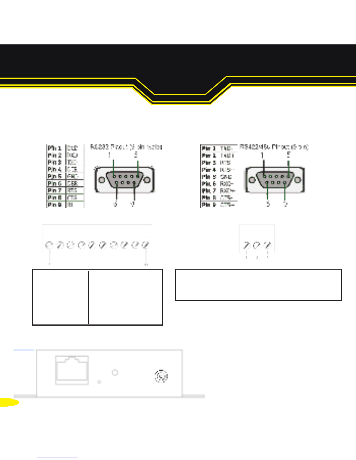
8.1. Serial DB9 Pin outs
8.2.
Serial Terminal Block Pin outs / Power Terminal Block Pin outs
RS232 RS422/485
8.3. Jack Plug
RS232 Port RS422/485 Port
Pin 1 TxD Pin 6 TxD+
Pin 2 RxD Pin 7 TxDPin 3 RTS Pin 8 RxD+/D+
Pin 4 CTS Pin 9 RxD-/DPin 5 GND Pin 10 GND
Pin 1 V+ Power Supply +
Pin 2 V- Power Supply Pin 3 Earth/Chassis Ground
8. Pin Outs
All power jacks are centre=positive, outer=ground
Devices that use PW-5xx PSUs: 5.5mm cylindrical
jack plug
Devices that use PW-8xx PSUs: 4mm cylindrical
jack plug
Page 19
1418
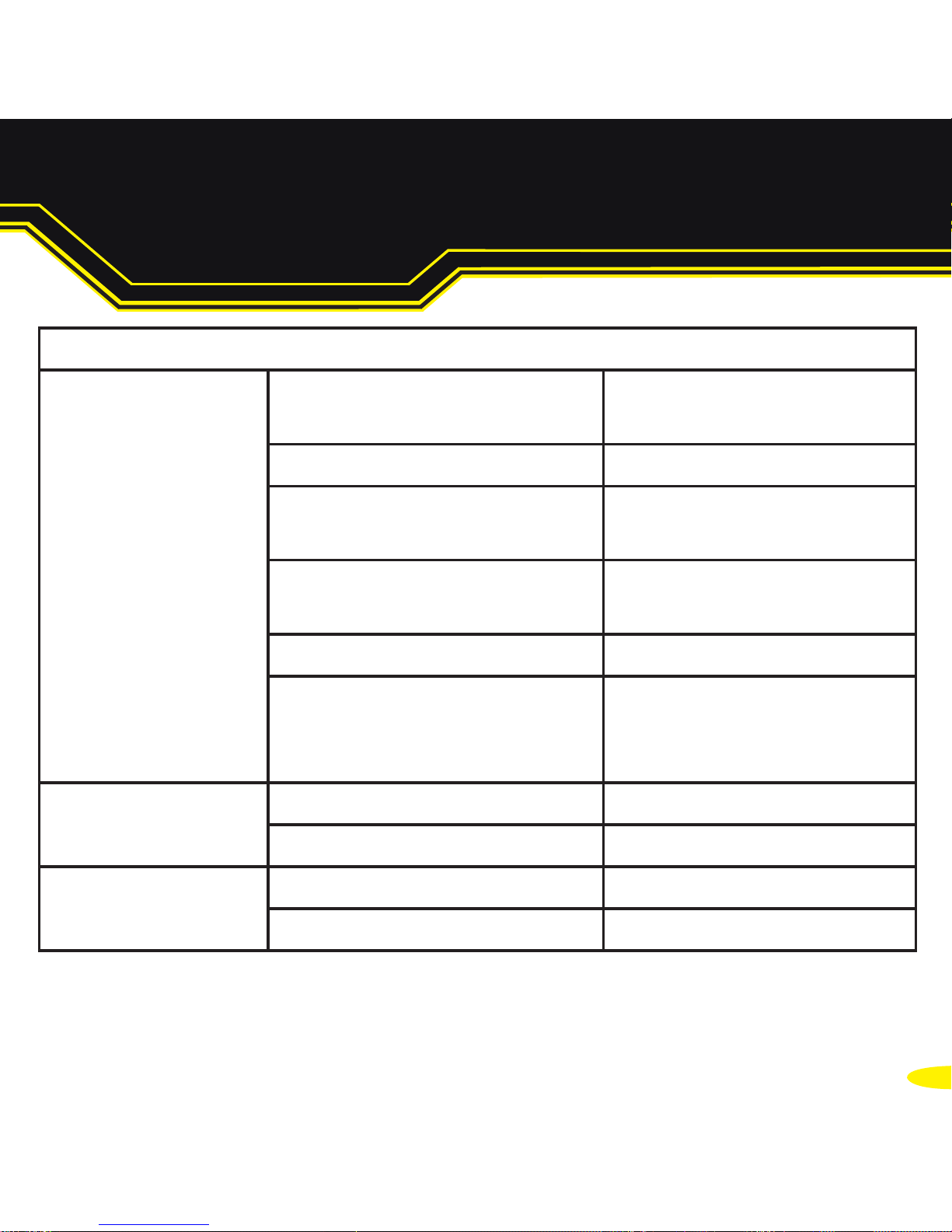
LED Information
Status LED Green Light on
Flashing Green
Device Ready
Flashing Yellow Changing Settings
Flashing between Red &
Green
Querying IP
Flashing between Green
& Red/Yellow
IP Problem
Flashing Green/Red Performing Hard Reset
Flashing between Green
& Yellow
Problem during
initialization (e.g.
Firmware Problem)
Serial Port LED Green light on Port Open
Flashing light on Data RX/TX
Ethernet LED Green light on Link established
Flashing Green Data RX / TX
For further configuration details, or technical information on the ES
product, please refer to Product Manual on CD
9. LED Information
Page 20

There’s so much more to Brainboxes
To enjoy the full benefits of Brainboxes, contact
UK - t. +44 (0)151 220 2500 f. +44 (0)151 252 0446
e. [email protected] w. www.brainboxes.com
Brainboxes Ltd. Unit 3c Wavertree Boulevard South,
Wavertree Technology Park, Liverpool, L7 9PF, UK
USA - TollFree. +1 (888) 958 5538
Japan - t. +81-3-3833-2500
Brainboxes Japan.
1-2-8 Shinjyuku,
Shinjyku-ku, Tokyo, 160-0022 Japan,
or visit www.brainboxes.com
 Loading...