

Page 1

¤
¤
¤¤
¤¤
2.1 EDITION January 1999
Photon
8 Port RS232
,
EV
H
[EVI
1
ERYE
P
Page 2

Guarantee.
FULL 36 MONTHS GUARANTEE.
We guarantee your interface card for a full 36 months from
purchase, parts and labour, provided it has been used in the
specified manner. In the unlikely event of failure return your
interface to your Dealer, with proof of purchase, who will
determine whether to repair or replace this product with an
equivalent unit.
COPYRIGHT.
COPYRIGHT © 1985-1999.
All rights reserved. No part of this hardware, circuitry or manual
may be duplicated, copied, transmitted or reproduced in any way
without the prior written consent of the Manufacturer.
Due to the Manufacturers commitment to quality, software is
subject to continuous improvements: information regarding
upgrades can be obtained from your supplier.
supplied to you by:
ACKNOWLEDGEMENT S.
IBM, COMPAQ, Hewlett Packard, H.P. and EPSON are
trademarks of the relevant companies. Windows is a trademark of
Microsoft.
Page 3

PCI Photon 8 Port RS232 Layout
INTRO 3
PHOTON 8 Port RS232 MANUAL
THE LAYOUT OF THIS MANUAL
Chapter 1 - PCI Photon 8 Port RS232 Hardware
Configuration, Summarises the features of the PCI
Photon 8 Port RS232 Card.
Chapter 2 – Installing the card into the PC,
Explains how to open the PC and insert a new serial card
Chapter 3 – PCI Photon 8 Port RS232 Software
Installation
This chapter details how to install and configure the
Photon 8 Port RS232 Card in Windows 3.x, Windows
95/98 and Windows NT.
Chapter 4 – RS232 Port Cabling
Page 4

PCI Photon 8 Port RS232 Index
INTRO 4
Index
PHOTON 8 Port RS232 MANUAL.............................3
CHAPTER 1 HARDWARE SPECIFICATIONS......6
Introduction........................................................................... 6
WARNING For Windows 98 Users Only.............................. 6
PCI Photon 8 Port RS232 Card Features............................... 6
PCI Photon 8 Port RS232 Card Specifications...................... 7
Configuring PCI Photon 8 Port RS232 Cards.........................7
CHAPTER 2 INSTALLING THE CARD .................8
Serial Carrd Installation.......................................................... 8
Problems!............................................................................ 10
CHAPTER 3 SOFTWARE INSTALLATION.........11
Introduction......................................................................... 11
Configuring Ports In Windows 3.x....................................... 11
Determining PCI Photon 8 Port RS232 Resources............... 11
Serial Solutions Installation for Windows 3.x...................... 13
Serial Port Installation. ........................................................ 14
Adding an PCI Photon 8 Port RS232 Serial Card. ................ 15
Settings for Photon 8 Port RS232 Card COM1 Present........ 17
Settings for Photon Card COM1 & 2 Present....................... 19
Settings for Photon Card COM1 to 4 Present....................... 21
Configuring The COM Ports................................................ 23
Changing Serial Port Settings.............................................. 23
Deleting Ports in Windows.................................................. 24
Restarting Windows............................................................. 24
Configuring Ports in Windows 95 and 98. ........................... 25
Windows 95/98 Installation Procedures............................... 25
PCI Photon 8 Port RS232 Card Settings In Win95/98.......... 27
PCI Photon Card Port Settings In Win 95/98....................... 29
Maximum Baud Rate Settings.............................................. 30
Configuring PCI Photon Ports In Windows NT................... 33
Software Installation............................................................ 33
Examining Card Configuration............................................ 34
Changing Serial Port Settings.............................................. 35
Page 5

PCI Photon 8 Port RS232 Index
INTRO 5
Advanced Port Settings........................................................ 36
Uninstalling Serial Solutions for Windows NT.................... 38
CHAPTER 4 RS232 PINOUTS AND PORT
CABLING...................................................................39
Introduction......................................................................... 39
The RS232 Standard............................................................ 39
Serial Port Pin Outs............................................................. 40
9 Pin D Serial Port Connection To Another PC. .................. 41
9 Pin D Serial Port To A Modem. ........................................ 43
9 Pin D Serial Port Loop Back Connector. ........................... 43
The Lynx Card Octopus Cable Pinouts................................ 46
Page 6

PCI Photon 8 Port RS232 Specifications
Chapter 2 Page 6
CHAPTER 1
HARDWARE SPECIFICATIONS
Introduction.
This chapter details the specifications of the PCI Photon 8
Port RS232 serial card. These half-sized cards will work happily
in any PCI 2.0 (or greater) compliant PC compatible.
WARNING For Windows 98 Users Only.
Each PCI Photon 8 Port RS232 Card should be fully installed
before adding additional PCI Photon 8 Port RS232 cards.
PCI Photon 8 Port RS232 Card Features.
* Eight independent RS232 Serial ports.
* Reliable communications up to 50 feet, 15m, and beyond!
* 100% 16C550 PC Compatible serial port, up to 230,400 baud.
16550 Compatible FIFO provides 128 byte input and 128 byte
output buffer on each port.
* Full modem control TXD, RXD, DSR, DCD, DTR, RTS, CTS
and RI signals.
* Fully double buffered for reliable asynchronous operation.
High speed integrated circuitry ensures operation with fast PC’s
e.g. 500 MHz Pentium II .
* Fully PCI 2.1 compliant.
* Fully Plug and Play
* Interrupt sharing system allows all ports to use a single interrupt
line while preventing any one port from hogging the processor.
Page 7
PCI Photon 8 Port RS232 Specifications
Chapter 2 Page 7
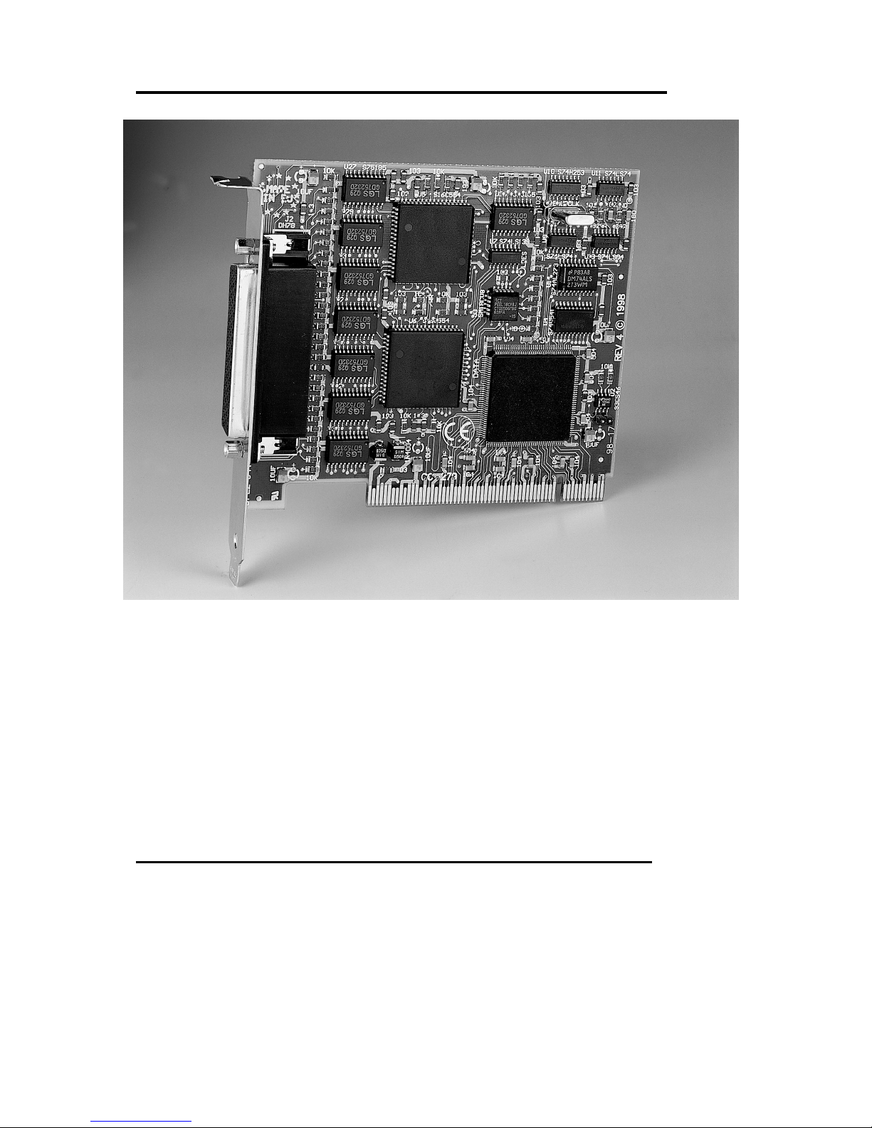
PCI Photon 8 Port RS232 Card Specifications.
Dimensions: 4.8 x 3.8 in, 120 x 95 mm
I/O Connection: 78 way female D connector
Fully moulded 8 Port cable with EITHER 9
or 25 pin D connectors.
Also, refer to Chapter 4 "RS232 Pinouts and Port Cabling" for
more detailed information on RS232 cabling, ports and pinouts.
Configuring PCI Photon 8 Port RS232 Cards.
The PCI Photon 8 Port RS232 cards are fully “ plug and
play”, and require no hardware configuration. They can be
installed "directly from the box".
Page 8

PCI Photon 8 Port RS232 Installing the Card
Chapter 2 Page 8
CHAPTER 2
INSTALLING THE CARD
Serial Carrd Installation.
Once the card has been correctly configur ed then it can be
installed in the PC.
After installing the card and configuring the software the
cables should be attached and communication with the serial
peripheral devices should be established.
Provided that the RS232 installation is attacked in this
orderly manner, everything should work first time. If it does not
then check the software selectable communications parameters,
Baud rate, Parity, stop bits first, and that the communications
program is attempting to access the serial port installed. If this
fails to solve the problem check the cable connections. Finally
check that the card is indeed configured as you believed!
NOTE: Always turn the computer OFF before installing or
removing any interface board. .!!!
After having made sure that the I/O address and if appropriate
jumpers are correctly set, now is the time to insert the PC Serial
card into the I /O connect or slot s in the com puter .
STEP 1: Before the PC card can be installed the power to the PC
MUST be switched OFF!
STEP 2: Remove t he case.
Page 9
PCI Photon 8 Port RS232 Installing the Card
Chapter 2 Page 9
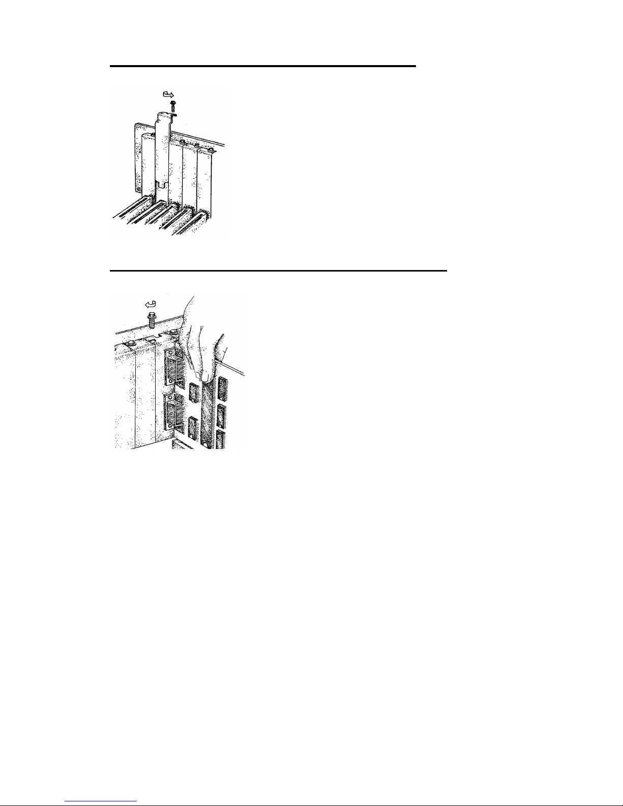
Figure 2-1. Removing Blanking Cover
STEP 3: Choose an empty appropriate
expansion slot. Remove the blanking cover
protecting the slot on the PC back panel.
KEEP the blanking cover screw safely for
later (Figure 2-14) .
Figure 2-2. Inserting The PC Serial Card.
STEP 4: Now insert the PC Serial card in
the available slot. Be careful to ensure that
the gold plated PCB fingers fits neatly into
the I/O expansion connector. Press down
firmly but evenly on the top of the PC
Serial card (Figure 2- 15) .
STEP 5: The D connector should fit neatly through the slot’s aperture to
the outside world. NB. Use the screw kept back from the blanking cover
to screw the PC Serial retaining bracket into the PC back panel housing.
STEP 6: Now replace the system units cover by carefully sliding
it down and back over the system unit. Replace the cover
mounting screws.
Attach all the cables.
The PC should power on in the normal way.
Page 10

PCI Photon 8 Port RS232 Installing the Card
Chapter 2 Page 10
Problems!
If the system fails to power up normally check the following:
i.) Ensure that th e PC S er ial car d is inst all ed cor r ectl y.
ii.) Ensure that other car ds in the PC have not been upset.
iii.) Ensure that the power is connected and the PC is switched
ON!
n
If all these have been checked and the PC still does not
power up then there is probably a conflict of I/O address between
the PC Serial card and another board in the PC. Ask your dealer to
check this
Page 11

PCI Photon 8 Port RS232 Software Installation
Chapter 3 Page 11
CHAPTER 3
SOFTWARE INSTALLATION
Introduction.
This section describes the software installation procedur e allowing
the PCI Photon 8 Port RS232 to be configured within the
Windows 3.x, Windows 95/98 and Windows NT operating
systems.
Configuring Ports In Windows 3.x
The Windows 3.x installation procedure consists of 3 steps:
1. Insert the PCI Photon 8 Port RS232 Card into a free PCI slot
and power up the PC.
2. Determine the resources that the PCI Photon 8 Port RS232 has
claimed.
3. Inform Windows 3. x of those resources.
Determining PCI Photon 8 Port RS232 Resources.
• Insert the card into a PC, as described in Chapter 2, power up
the PC
• From DOS Run BBCARDS.EXE, Found on the supplied
CDROM, by typing the following:
HVMZI"@HMWOMQK@WWYXMP@TGM@FFGEVHWI\I
Where <drive>is the dr i ve contai ning t he suppl ied di sk.
BBCARDS.EXE will display a message that looks similar
to the following ( the values displayed may differ due to resource
availability):
Page 12

PCI Photon 8 Port RS232 Software Installation
Chapter 3 Page 12
PCI Photon 8 Port RS232 Users:
card 1 is on bus 0, device 16, function 0
Card ID=2, revision 3: Photon 8 Port RS232
interrupt line IRQ11 has been assigned
8 sets of 16550-compatible registers are at Bank I/O a ddr e ss FF40
SISR is at I/O address FFA0
Baud clock control i s at I/ O addre ss FFC0
Write 0xf6 for /8 (default), 0xf2 for /4, 0xd6 for /2, 0xd2 for /1.
Note the IRQ, I/O address and SISR Address values
In our example:
The IRQ = 11
The IRQ is the interrupt line shared amongst the Photon 8 Port
RS232 card’s serial ports
The Bank address = FF40
The Bank add ress determ ines the COM Po rt Base addresses i n the
following manner:
COM Base of port 1 = the Bank Address
COM Base of port 2 = the Bank Address + 8hex
COM Base of port 3 = the Bank Address + 10hex
COM Base of port 4 = the Bank Address + 18hex
COM Base of port 5 = the Bank Address + 20hex
COM Base of port 6 = the Bank Address + 28hex
COM Base of port 7 = the Bank Address + 30hex
COM Base of port 8 = the Bank Address + 38hex
The SISR Address = FFA0
The SISR Address is the Shared Int errupt Stat us Register, th is is a
read-only register indicating which of the four serial ports requir es
service by the driv er sof twar e.
Page 13
PCI Photon 8 Port RS232 Software Installation
Chapter 3 Page 13
Serial Solutions Installation for Windows 3.x
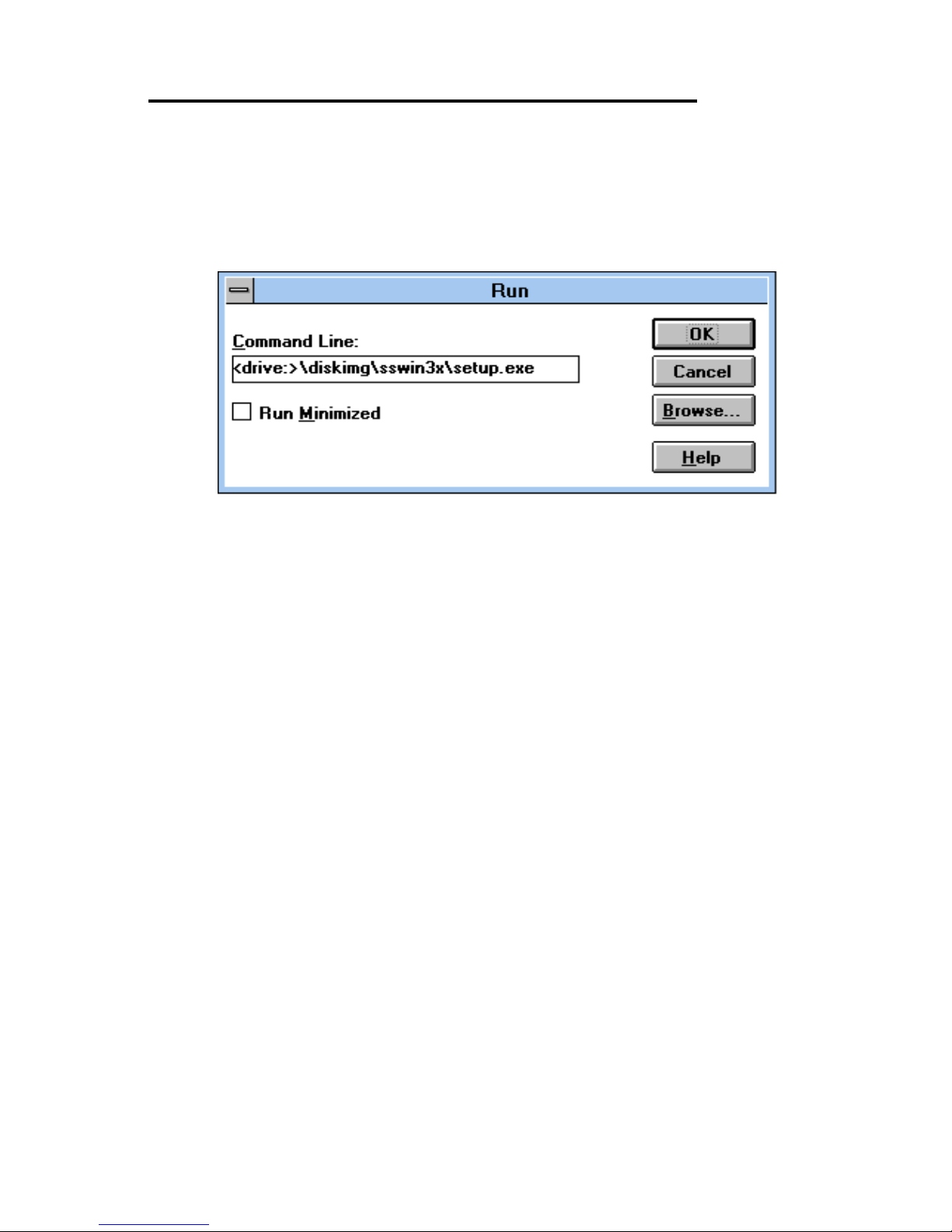
To install the software from the supplied disk, insert the
disk, from Windows Program Manager’s File menu choose
"Run" and in the Command Line entry window type
<drive:>\diskimg\sswin3x\setup.exe (CDROM) or
<drive:>\setup.exe (F L OPP Y)
(where <drive:> is the path to installation disk).
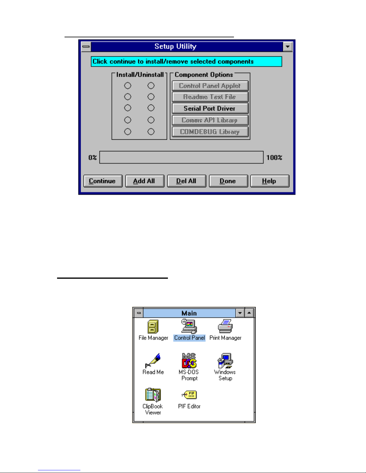
Selecting the "OK" button shows the setup program main
Selecting the "OK" button shows the setup program main screen,
Figure 4-1, which will automatically select components for
installation that have not already been installed. Selecting the "Del
All" button will select all installed components for deletion and
selecting "Add All" chooses all uninstalled components for
installation. Several of the components have user selectable
parameters, e.g. target install directory, which can be changed by
clicking on the button. These options may not be changed once
the components have been installed. A README.TXT file on the
disk contains details of the latest updates to this software,
Note: If it is necessary to re-install an OLDER version of a
component then the NEWER version component must be FIRST
removed by selecting the component’s button in the "Uninstall"
column then selecting the "Continue" button.
If only logical ports COM1 to COM9 are to be used then
de-select the Comms API library option button in the "Install"
column. This library is only necessary to allow the use of logical
ports greater than COM9 e.g. COM10, COM11 etc.
Page 14
PCI Photon 8 Port RS232 Software Installation
Chapter 3 Page 14
Figure 3-1. Setup Program Main Display.
Selecting the Continue button will start the installation process.
When the setup program has finished select the Done button. A
Windows restart message will be shown only if the Windows
communications driver option has been selected, and you should
choose Yes to allow the new driver to run.
Serial Port Installation.
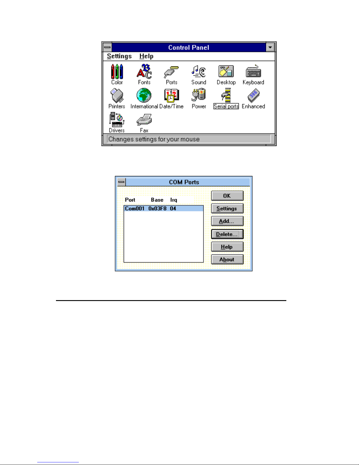
• From Main, select Control Panel:
Page 15
PCI Photon 8 Port RS232 Software Installation
Chapter 3 Page 15
• Click on Serial Port s:
The following dialogue will be displayed:
Adding an PCI Photon 8 P ort RS232 Serial Card.
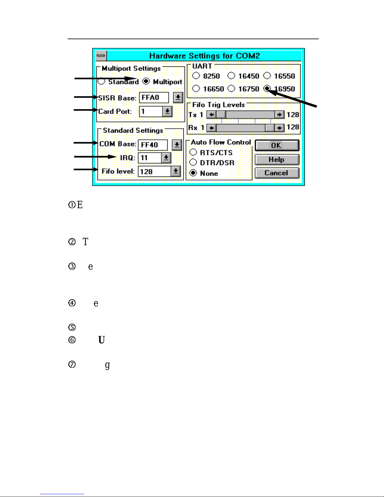
For each port on the Photon 8 Port RS232 card we need to
ADD a port and fill in the following 7 settings in the order given.
Default values for the communications settings are given
whenever the ADD button is used, 9600 baud, no parity, 8 data
bits and 1 stop bit.
Page 16
PCI Photon 8 Port RS232 Software Installation
Chapter 3 Page 16
Figure 3-2. PCI Photon 8 Port RS232 Serial Card Settings.
Multiport Settings:-
j
Each Port should have the Multiport button selected, this tells
Windows 3.x that the port is one of several ports using a SISR
(shared interrupt status register).
k
The SISR Base address must be set as indicated by the
BBCARDS progr am .
l
The Card Port setting tells Windows whether this is the first,
second, third, fourth port etc. of the Photon 8 Por t RS232 card.
Standard Settings:-
m
The COM Base is determined from the Bank Address as
described above, P63.
n
The IRQ must be set as i nd icat ed by th e BBCARDS pr o gram.
o
The UART on the photon port is an enhanced 16550 called the
16950.
p
Having selected the 16950 you can then set the FIFO level at
128 bytes.
j
k
l
m
n
p
o
Page 17
PCI Photon 8 Port RS232 Software Installation
Chapter 3 Page 17
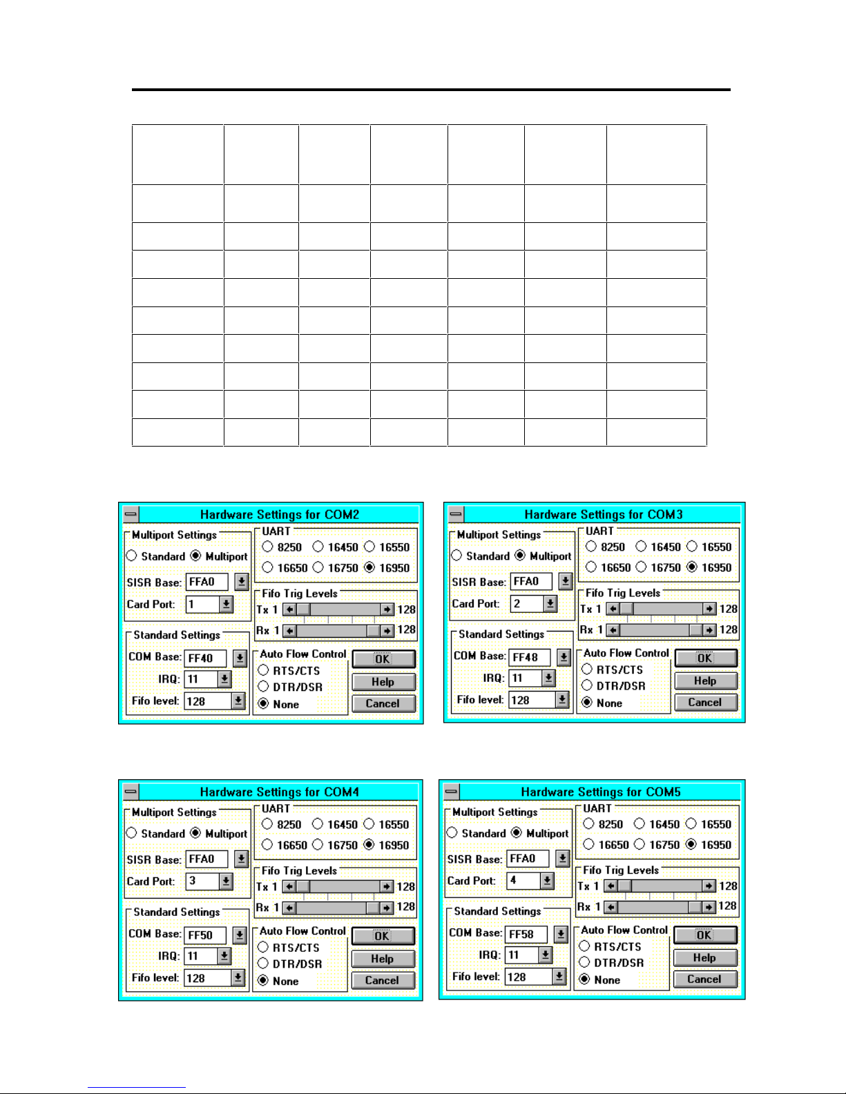
Settings for Photon 8 Port RS232 Card COM1 Present
COM
Port
SISR Card
Port
COM
Base
IRQ UART FIFO
Trip
BBCARDS
Values *
FFA0 FF40 11
COM2 FFA0 1 FF40 11 16950 Default
COM3 FFA0 2 FF48 11 16950 Default
COM4 FFA0 3 FF50 11 16950 Default
COM5 FFA0 4 FF58 11 16950 Default
COM6 FFA0 5 FF60 11 16950 Default
COM7 FFA0 6 FF68 11 16950 Default
COM8 FFA0 7 FF70 11 16950 Default
COM9 FFA0 8 FF78 11 16950 Default
*The BBCARDS Values may be different from your machine.
Card Port 1 Card Port 2
Card Port 3 Card Port 4
Page 18
PCI Photon 8 Port RS232 Software Installation
Chapter 3 Page 18
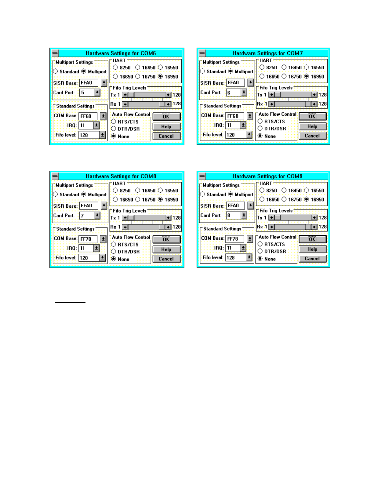
NOTE: The only settings that change from port to port are the COM
Base and the Card Port Settings
Card Port 5 Card Port 6
Card Port 7 Card Port 8
Page 19
PCI Photon 8 Port RS232 Software Installation
Chapter 3 Page 19
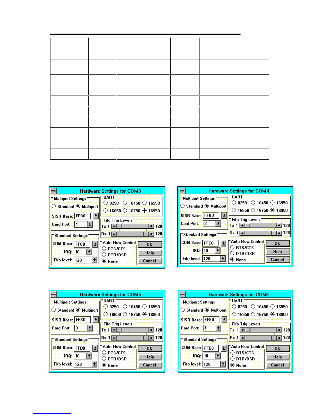
Settings for Photon Card COM1 & 2 Present
COM
Port
SISR Card
Port
COM
Base
IRQ UART FIFO
Trip
BBCARDS
Values*
FF80 FFC0 10
COM3 FF80 1 FFC0 10 16950 Default
COM4 FF80 2 FFC8 10 16950 Default
COM5 FF80 3 FFD0 10 16950 Default
COM6 FF80 4 FFD8 10 16950 Default
COM7 FF80 5 FFE0 10 16950 Default
COM8 FF80 6 FFE8 10 16950 Default
COM9 FF80 7 FFF0 10 16950 Default
COM10 FF80 8 FFF8 10 16950 Default
*The BBCARDS Values may be different from your machine.
Card Port 1
Card Port 2
Card Port 3 Card Port 4
Page 20
PCI Photon 8 Port RS232 Software Installation
Chapter 3 Page 20
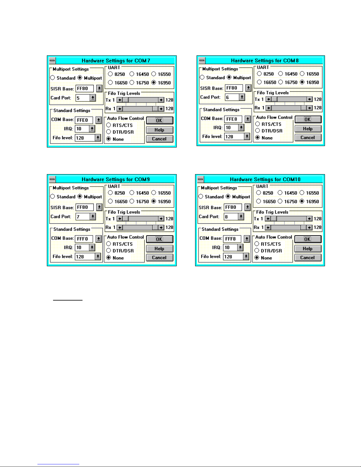
NOTE: The only settings that change from port to port are the COM
Base and the Card Port Settings
Card Port 5 Card Port 6
Card Port 7
Card Port 8
Page 21
PCI Photon 8 Port RS232 Software Installation
Chapter 3 Page 21
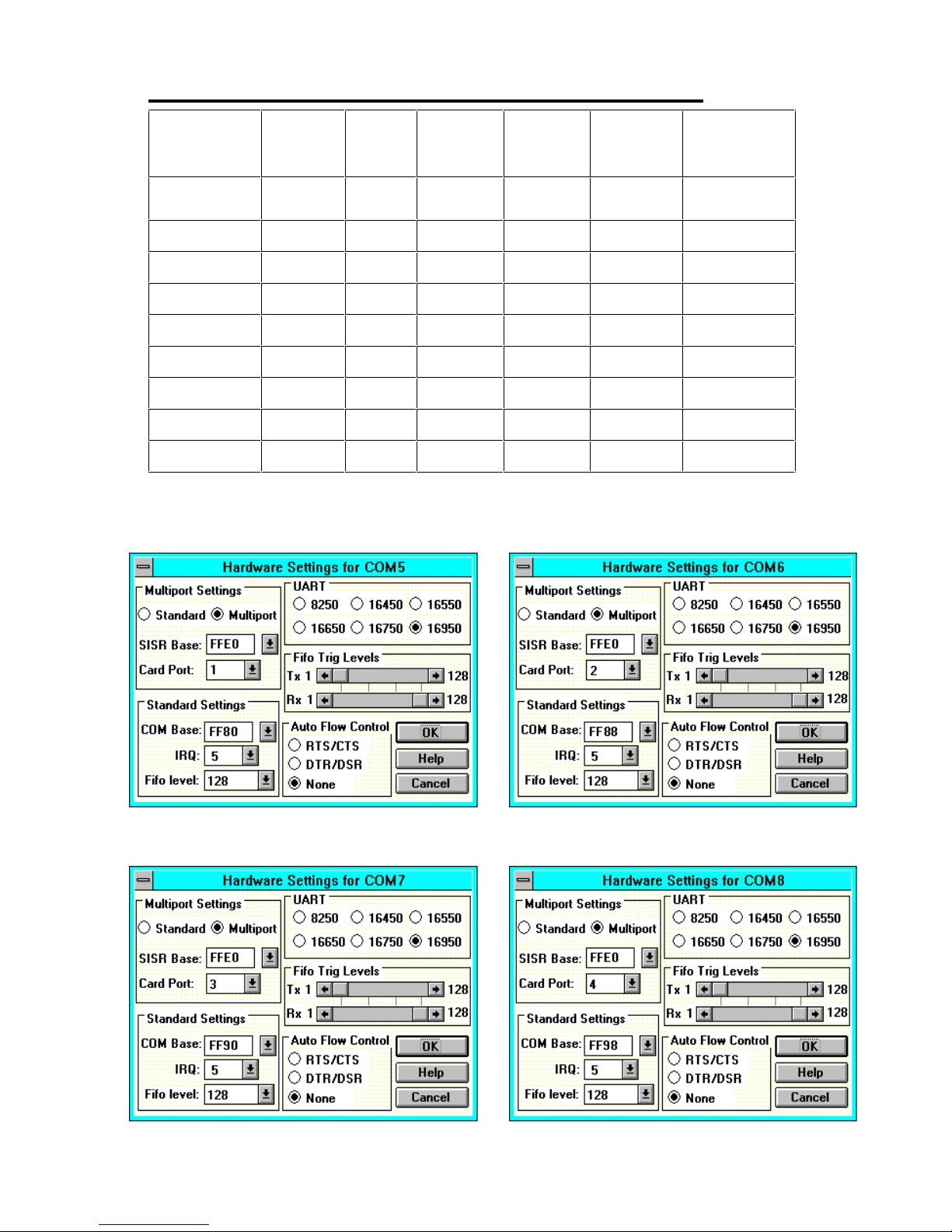
Settings for Photon Card COM1 to 4 Present
COM
Port
SISR Card
Port
COM
Base
IRQ UART FIFO
Trip
BBCARDS
Values*
FFE0 FF80 5
COM5 FFE0 1 FF80 5 16950 Default
COM6 FFE0 2 FF88 5 16950 Default
COM7 FFE0 3 FF90 5 16950 Default
COM8 FFE0 4 FF98 5 16950 Default
COM9 FFE0 5 FFA0 5 16950 Default
COM10 FFE0 6 FFA8 5 16950 Default
COM11 FFE0 7 FFB0 5 16950 Default
COM12 FFE0 8 FFB8 5 16950 Default
*The BBCARDS Values may be different from your machine.
Card Port 1
Card Port 2
Card Port 3 Card Port 4
Page 22
PCI Photon 8 Port RS232 Software Installation
Chapter 3 Page 22
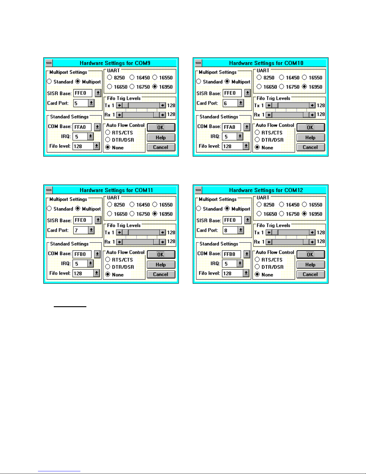
NOTE: The only settings that change from port to port are the COM
Base and the Card Port Settings
Card Port 5
Card Port 6
Card Port 7 Card Port 8
Page 23
PCI Photon 8 Port RS232 Software Installation
Chapter 3 Page 23
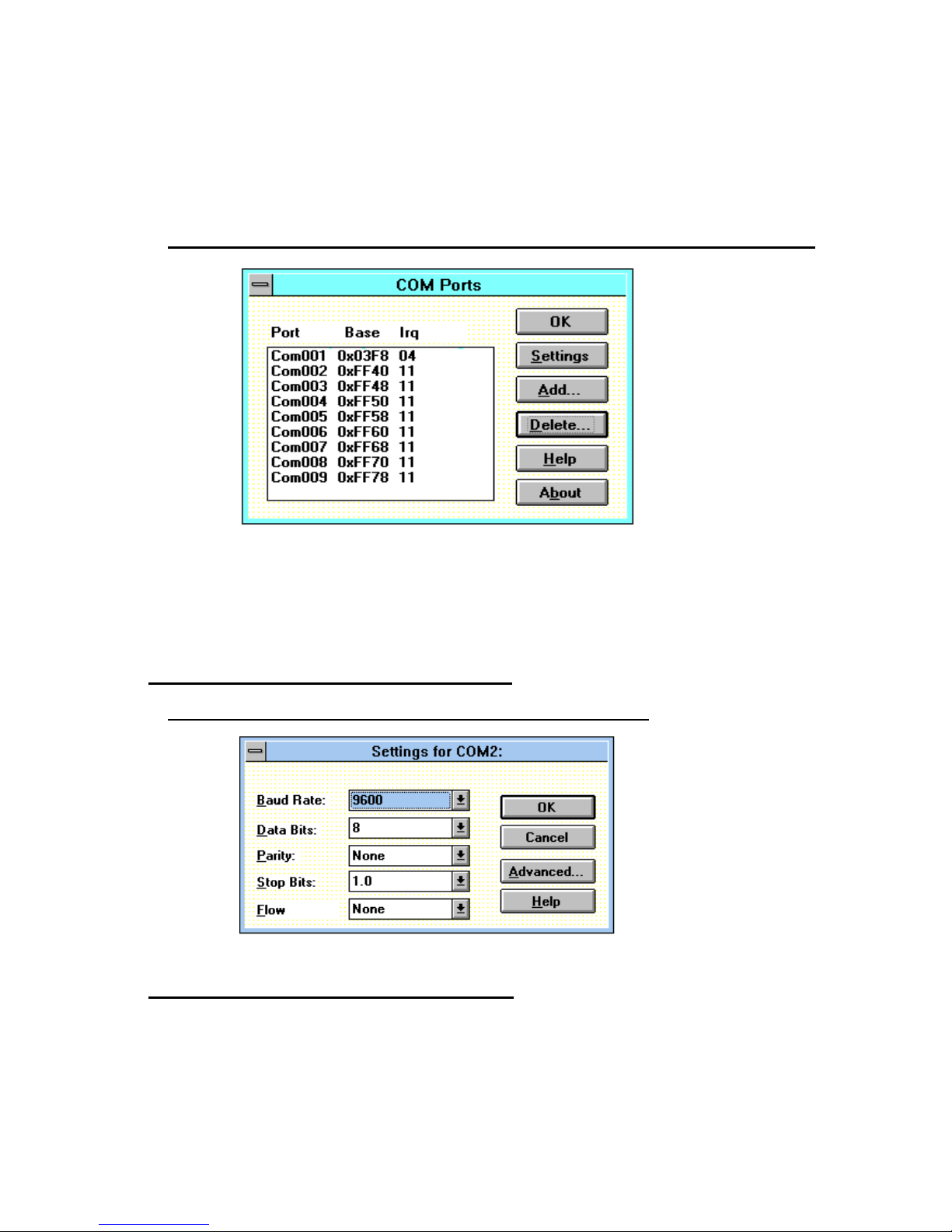
Select the OK button to finish adding the port. This will display a
Windows restart message, but do not restart until you have
installed all eight ports. Be sure to restart Windows after all serial
ports have been added so that the new configuration takes effect.
Figure 3-3. After Adding a PHOTON Card (COM1 present).
Note: Adding a port automatically sets default values for the
communications settings to 9600 baud, no parity, 8 data bits and 1
stop bit. These values can be changed as described below.
Configuring The COM Ports.
Figure 3-4 PCI Photon Card Comms Settings
Changing Serial Port Settings
Once the Photon 8 Port RS232 card has been installed it
may be necessary to change the communications settings in the
COM Ports to match the baud rate, parity settings etc. of the
remote serial devi ce.
Page 24

PCI Photon 8 Port RS232 Software Installation
Chapter 3 Page 24
l
Highlight the serial port required, e.g. COM2., in Serial Ports,
Control Panel
l
Click on the Settings button to change the communications
settings, Figure 3-3.
l
Select the appropriate communications settings, which must
match the communications settings on the remote device.
l
Click on the OK button to leave the communications Settings
window.
The Advanced option in Settings can be used to change the
hardware settings to match a new base address and IRQ because
the PC’s BIOS has reallocated the PCI resources due to the
installation of other new hardware.
l
Click on the Advanced button for the hardware settings
window, Figure 3-4. Enter the 7 options in the same manner as
described in the section “Adding a PCI Photon 8 Port RS232
Serial Card”
Deleting Ports in Windows.
The Delete button can be used to discard the entries of
ports that have been removed from the system.
Note. Due to problems with the standard Windows Serial
Ports Applet in the Control Panel Make sure that there are no
gaps in the numbering of the first four serial ports, COM 1-4. If
necessary leave a “place holder” otherwise Windows may
automatically reorder the COM port numbers resulting in serious
problems.
Restarting Windows.
Whenever certain values have been changed in the
Advanced window, a message prompting the user to restart
Windows will appear. Once ALL necessary changes have been
made Windows should be restarted so that the new settings may
come into effect.
Page 25

PCI Photon 8 Port RS232 Software Installation
Chapter 3 Page 25
Configuring Ports in Windows 95 and 98.
Although covering the installation of the PCI Photon 8 Port
RS232 cards into the Windows 95 operating system the procedure
is also valid, with only minor differences, in Windows 98. The
Windows 95 environment now supports up to 255 standard serial
ports.
Windows 98
The Windows 98 operating system procedure is the same as for
Windows 95 with only minor differences. The only significant
difference is that only one PCI Photon Card should be added to the
PC per restart. E.g. if three PCI Photon cards are to be installed
then the whole of the following procedure needs to be carri ed out
three times.
Windows 95/98 Installation Procedures
• Insert the car d in a f r ee PCI sl ot, power up t he P C.
• Windows 95 should then load normally. During the booting
process, Windows 95 will detect the card and briefly display a
message box indicating the detection process.
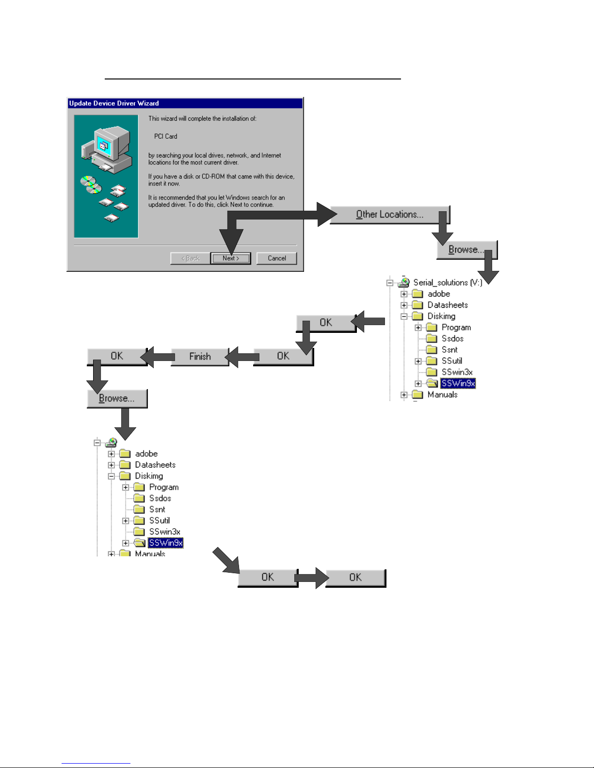
• Windows will then display the "Update Device Driver Wizard",
requesting “insert any disk which came with the PCI card”.
Insert the Serial Solutions CDROM installation disk into an
appropriate drive and click 'Next' and follow the path laid out
below.
Page 26
PCI Photon 8 Port RS232 Software Installation
Chapter 3 Page 26
Figure 3-5 Windows 95 Installation from CD
If you are installing from a floppy disk click Next and the
software will be found on the floppy disk and installed.
Page 27
PCI Photon 8 Port RS232 Software Installation
Chapter 3 Page 27
• After copying the files Windows 95 will then detect each of
the serial ports in turn and install them as Photon 8 Por t RS232
communications ports.
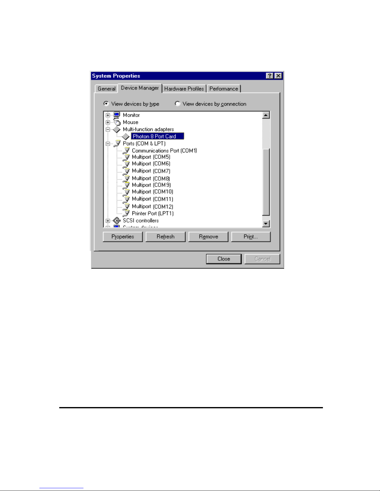
The Device Manager, reached by clicking on ’System’ in the
Control Panel, now shows the presence of the PCI Photon 8 Port
RS232 Card under Multi-function adapters. See below.
If there are no other serial port cards installed above COM 4, the
PCI Photon 8 Port RS232 will appear as COM5 –COM12. If there
are already more than 5 COM ports installed the Multiport card
ports will appear as the next highest available COM ports. PCI
Photon Cards do not appear with the COM1 to COM4 assignment
since these ports are r eser v ed f or l egacy P CI car ds.
PCI Photon 8 Port RS232 Card Settings In Win95/98.
• Double clicking a card entry under the "Multi-Function
Adapters", in Device Manager will display general properties for
the selected card.
Page 28
PCI Photon 8 Port RS232 Software Installation
Chapter 3 Page 28
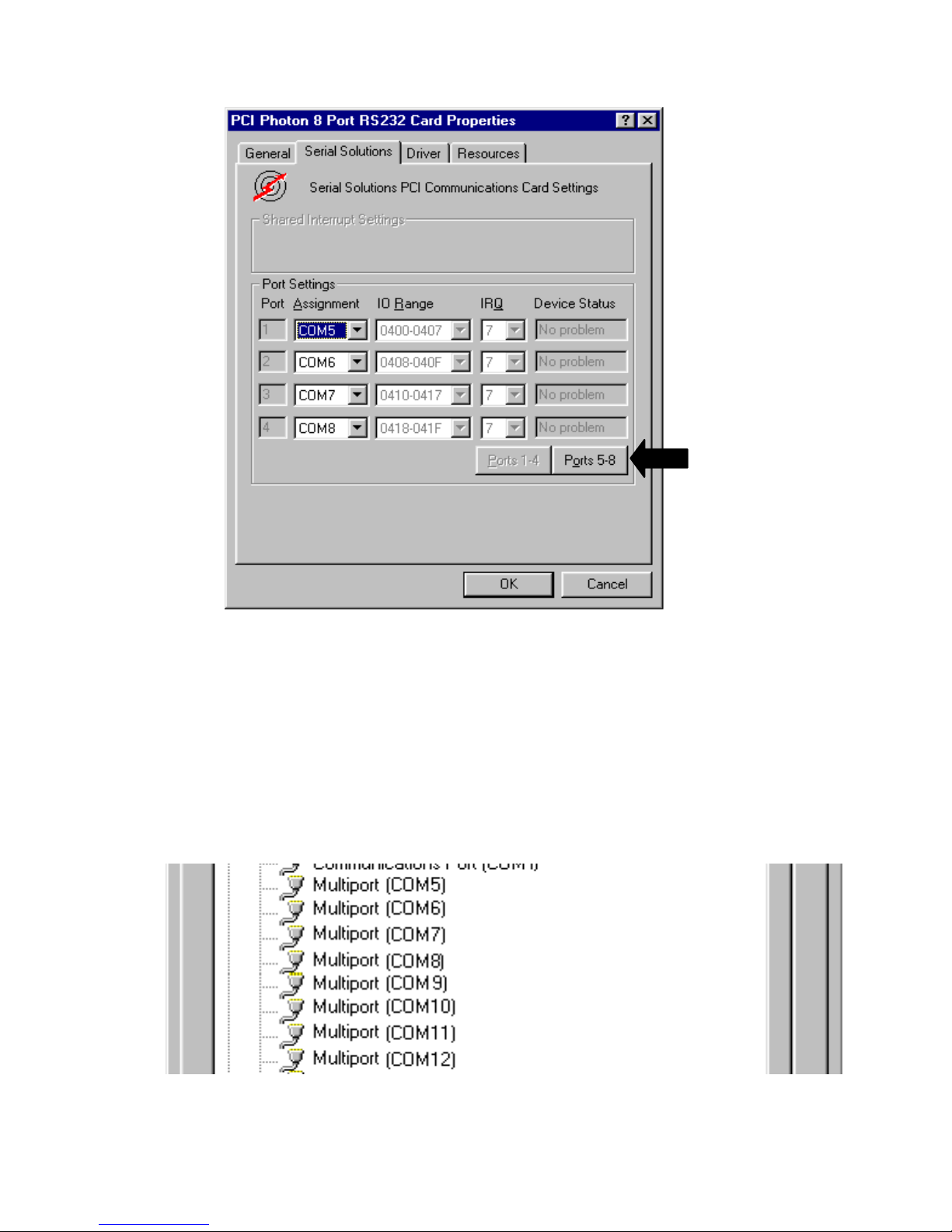
• Clicking on the Serial Solutions tab will display:
Some communications applications require the serial ports
they access to be as named COM 4 or lower. The COM port
assignment may be changed, simply by selecting a new COM port
value from the pull down menu relevant to the port. However,
COM port usage other than those for the selected card itself are
not checked, so it is advisable to f irst check which COM ports ar e
in use - port availability can be checked by viewing the Device
Manager:
Click to access
Ports 5-8
Page 29
PCI Photon 8 Port RS232 Software Installation
Chapter 3 Page 29
All COM ports present will be listed under the entry "Ports
(COM & LPT)." The above screenshot indicates that COM13 and
above are not installed.
PCI Photon Card Port Settings In Win 95/98.
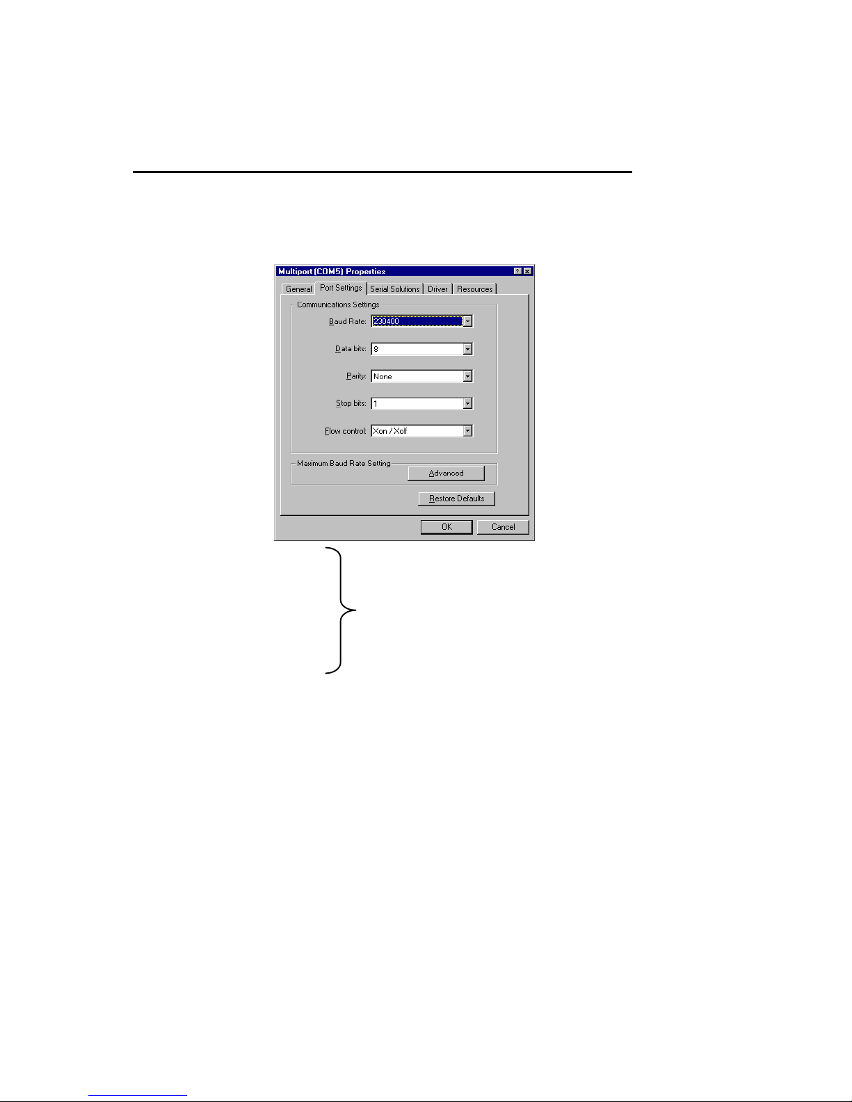
Double clicking upon an individual port entry in the Device
Manager, and selecting the Port Settings tab will display:
Settings available in this window are:
1. Baud Rate.
2. Data Bits.
3. Parity.
4. Stop Bits.
5. Flow Control.
6. Restore Defaults - When clicked, this will reset the selected
port to the default values of:
Baud Rate: 9600
Data Bits: 8
Parity: None
Stop Bits: 1
Flow Control: Xon / Xoff
Change to suit remote device.
Page 30
PCI Photon 8 Port RS232 Software Installation
Chapter 3 Page 30
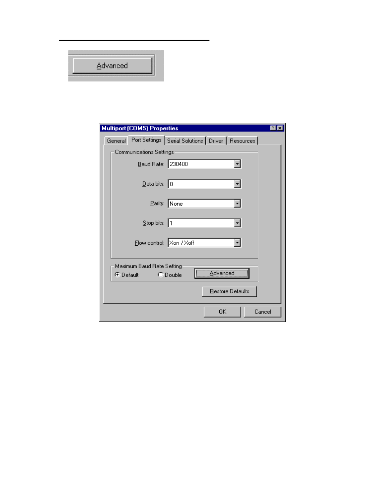
Maximum Baud Rate Settings .
Clicking the Advanced button gives the user the option of
changing the behaviour of the driver.
The Default behaviour of the driver is to operate on a wysiwyg
(what you see is what you get) basis, meaning the Baud rate that
an application selects will be the Baud rate of the data leaving the
port.
Selecting Double changes the driver behaviour in the
following ways…
For applications using the above dialogue e.g. HyperTerminal
there will be no change.
For applications directly calling the Win32 API e.g. Dial Up
Page 31
PCI Photon 8 Port RS232 Software Installation
Chapter 3 Page 31
Networking the selected baud rate is doubled, i.e. selecting
115,200 gives a real baud rate of 230,400.
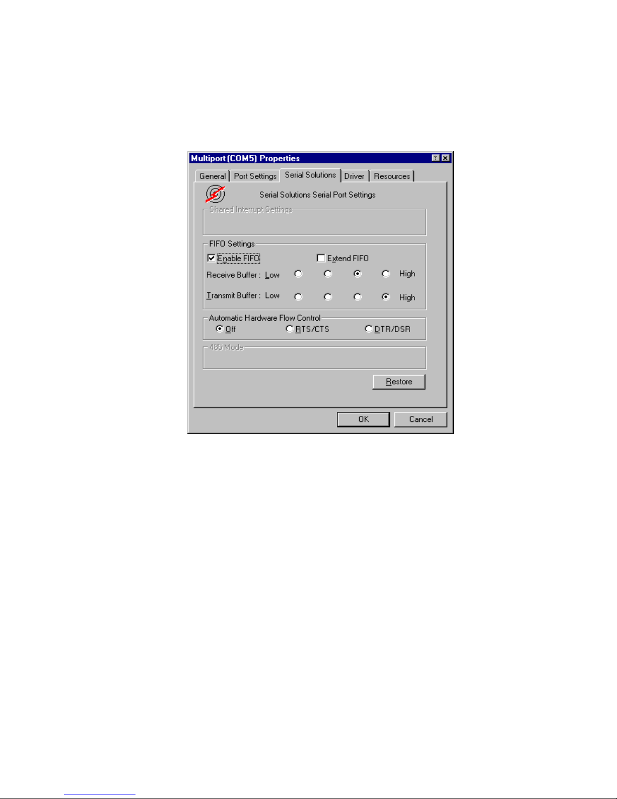
Selecting the Serial Solutions tab of the selected port properties
Window will display:
Settings available in this window are:
1. FIFO settings.
• Enable FIFO - turns the selected ports FIFO buffer on or
off. It is strongly recommended that the FIFO for all ports
is left enabled.
• Extend FIFO – When the FIFO is enabled the default
FIFO size is 16 Bytes. The extended FIFO size is 128
Bytes.
• Receive Buffer - These settings allow the selection of a
receiver FIFO trigger setting. Selecting a low value will
allow the interrupt to be serviced quicker, which is good
for slow machines. If you have a fast machine, setting a
high value will give you more time for multi-tasking
operations. The trigger options in the case of the Photon
Page 32

PCI Photon 8 Port RS232 Software Installation
Chapter 3 Page 32
Card’s 128 byte FIFO are 1, 32, 64 and 112.
• Transmit Buffer - These settings allow the selection of a
transmitter FIFO trigger setting. Selecting a low value will
send fewer data-bytes per interrupt, and this is
recommended if you are communicating to a slower
machine. Selecting a high value will send more data-bytes
per interrupt, and will give more time for multi-tasking
operations. The trigger options in the case of the Photon
Card’s 128 byte FIFO are 1, 32, 64 and 112.
2. Restore-
Clicking on this port will restore the port setting
of the Serial Solutions tab to the values set on entry to this
page.
Page 33
PCI Photon 8 Port RS232 Software Installation
Chapter 3 Page 33
Configuring PCI Photon Ports In Windows NT.
Microsoft Windows NT Provides built in support for 255
standard serial ports. To setup your PCI Photon 8 Port RS232
serial card you should follow these steps. Please note that to
change any kind of hardware configuration under Windows NT
you must be logged in as a user with Administrator level
privileges, if you do not have these please contact your system
administrator.
Software Installation.
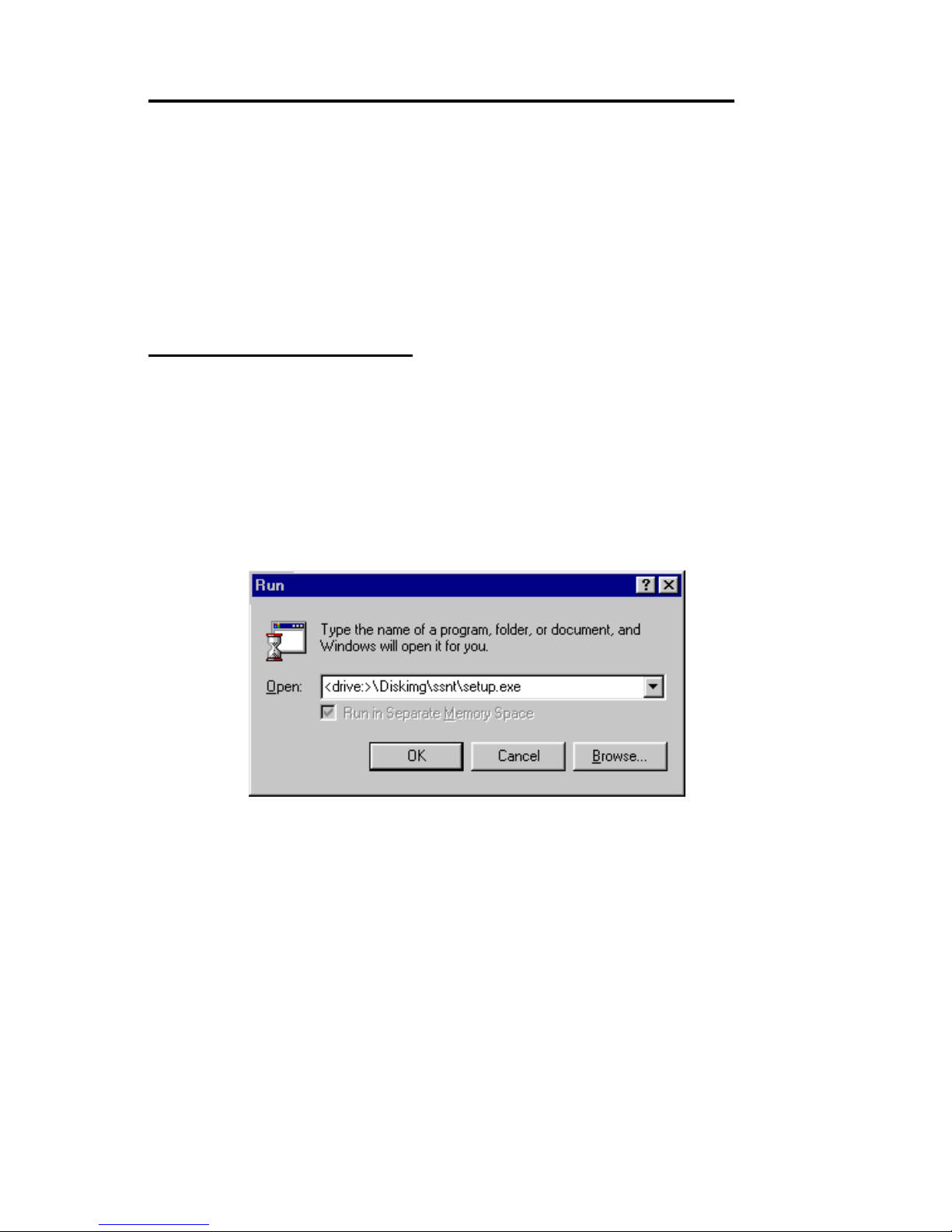
Insert the PCI Photon 8 Port RS232 Card into your PC, as
described in chapter 2, and restart. Place the supplied Serial
Solutions CDROM in a suitable drive and from the Start Menu
choose Run and enter the path Below. If you are installing from
floppy disk the path will be <drive:>\setup.exe. (where <drive:>
is the path to the drive containing the installation disk).
Selecting the "OK" button begins the conventional
InstallShield setup process, there are no options for this
installation, all items must be installed in the NT System32
directory. Once the software has been installed, you may run the
Serial Solution Control Panel applet
• InstallShield will then install the driver software automatically
- it will then copy the necessary files and start itself. This
automatically detects your new PCI serial card(s) and does not
require any further system restarting.
Page 34
PCI Photon 8 Port RS232 Software Installation
Chapter 3 Page 34
Examining Card Configuration.
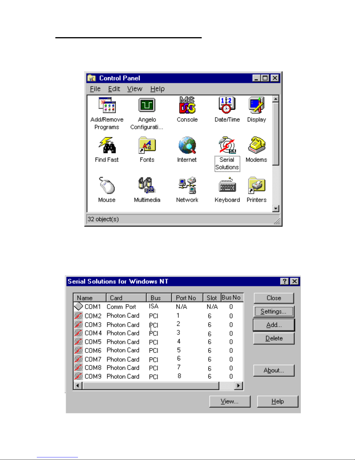
Go to Control Panel (Start Menu/Settings/Control Panel)
and double click on Serial Solutions:
After adding a Photon 8 Port RS232 Card (COM 1 present) you
will be presented with a Serial Solutions Port Configuration
window:
Page 35
PCI Photon 8 Port RS232 Software Installation
Chapter 3 Page 35
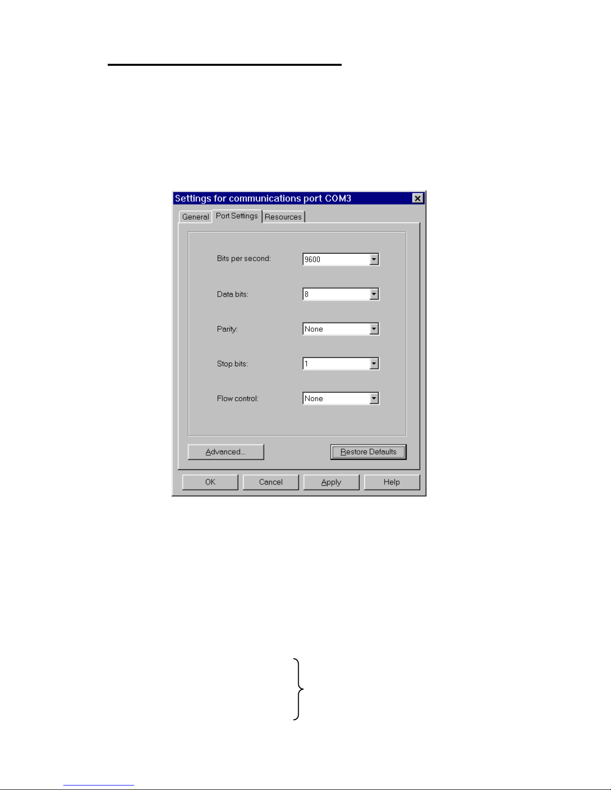
Changing Serial Port Settings
Adding a Photon 8 Port RS232 Card to the system automatically
sets default values for communications settings to 9600 Baud, 8
Data Bits, No Parity and 1 Stop Bit.
To view the settings of a port, select it from the main dialogue,
then click on Settings. Clicking on Port Settings from the
resulting dialogue opens up the following window.
Settings available in this window are:
1. Baud Rate - determines the baud rate at which the selected
port operates, providing it is not overridden by any serial
comms applications in use. PCI Photon 8 Port RS232 will
operate correctly up to 230,400 baud at distances of up to 10
meters,
Note: Many serial comms applications will not actually
register the ports as running at baud rates of above 115200.
2. Data Bits.
3. Parity.
4. Stop Bits.
Change to suit remote device.
Page 36
PCI Photon 8 Port RS232 Software Installation
Chapter 3 Page 36
5. Flow Control.
6. Advanced - see the section below, titled "Advanced Port
Settings."
7. Restore Defaults - when clicked, r esets the selected COM por t
to the following values:
Baud Rate: 9600
Data Bits: 8
Parity: None
Stop Bits: 1
Flow Control: Hardware
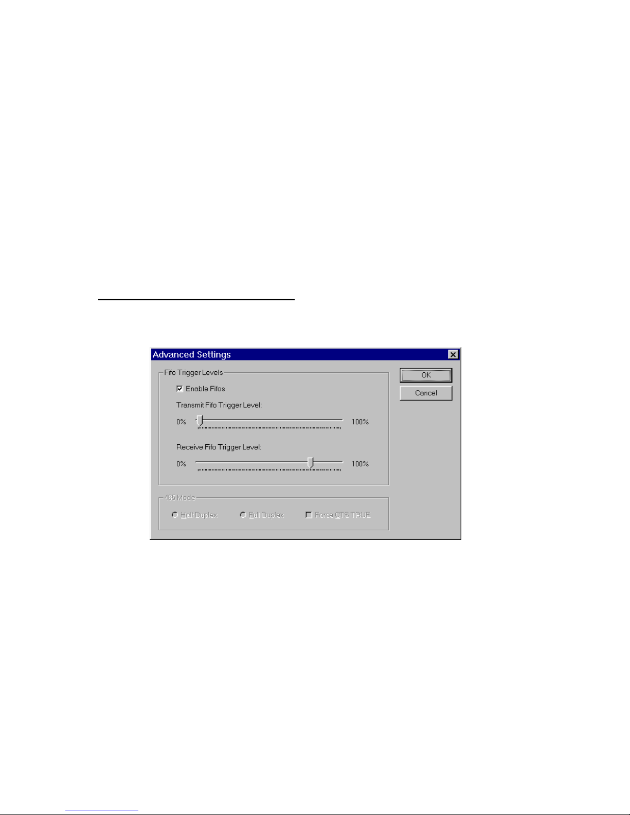
Advanced Port Settings.
When the Advanced button of Port Settings in selected the
following dialogue is displayed:
Settings available in this window are:
1. FIFO settings.
• Use FIFO Buffers - turns the selected ports FIFO
buffer on or off. I t is strongly recommended that the
FIFO for both ports is left enabled.
• Receive Buffer - These settings allow the selection
of a receiver FIFO trigger setting. Selecting a low
value will lessen the likelihood of data loss due to
overrun errors when Photon 8 Port RS232 cards are
installed in slower host PCs running ports at higher
Page 37

PCI Photon 8 Port RS232 Software Installation
Chapter 3 Page 37
baud rates. Setting a high value will give better
overall system performance when the host PC has
multiple applications running simultaneously.
• Transmit Buffer - These settings allow the
selection of a transmitter FIFO trigger setting.
Selecting a low value will send fewer data-bytes
per interrupt, this is recommended if you are
communicating to an older external serial device.
Setting a high value will give better overall system
performance when the host PC has multiple
applications running simultaneously.
Be warned, many older devices or even modern
PC’s without PHOTON ports cannot deal with
long bursts of data, especially at high Baud
rates.
2. Defaults - When clicked this button resets the advanced
properties to the followed settings:
Use FIFO Buffers: On (checked)
Transmit Buffers: 1%
Receive Buffers: 80%
Page 38
PCI Photon 8 Port RS232 Software Installation
Chapter 3 Page 38
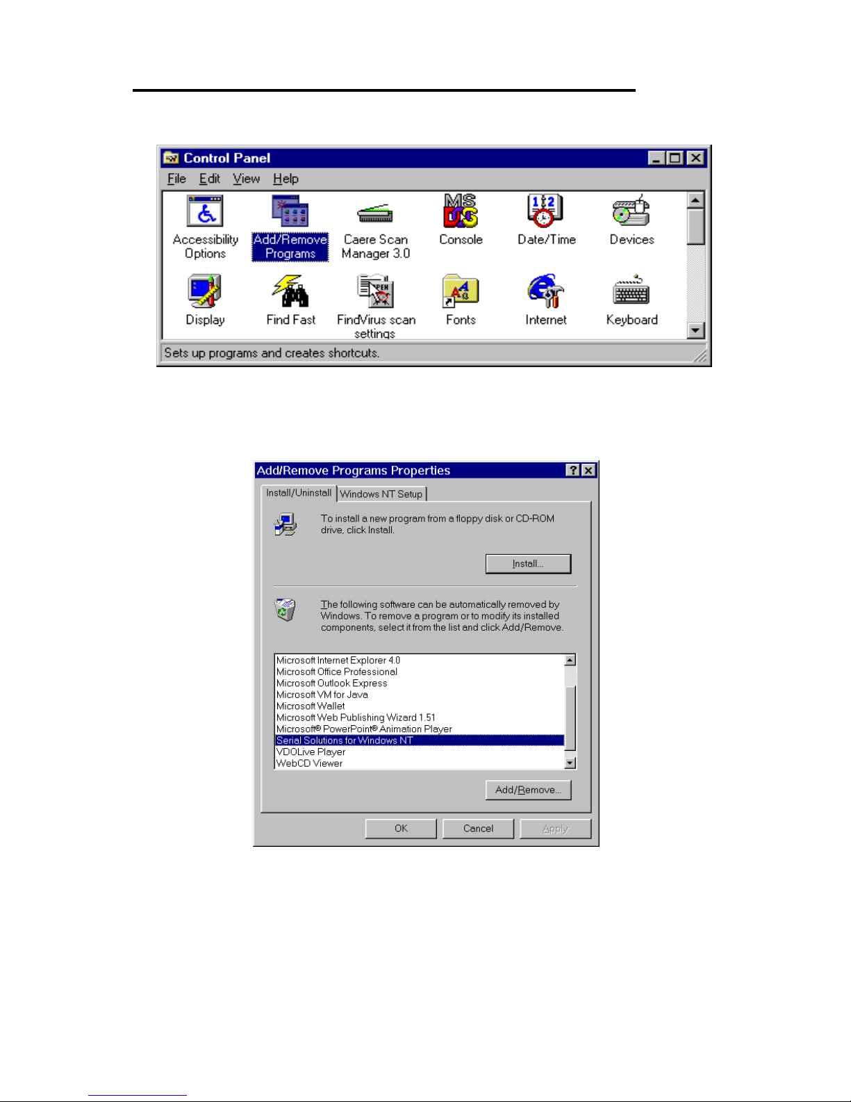
Uninstalling Serial Solutions for Windows NT
To uninstall Serial Solutions for Windows NT:
• From Control Panel, open the Add/Remove Programs applet,
then be certain to close the Control Panel.
• Select from the list Serial Solutions for Windows NT.
• Click the Add/Remove button.
Windows NT will then uninstall the Serial Solutions applet,
without the need for restarting your machine.
Page 39
PCI Photon 8 Port RS232 Index
Chapter 4 Page 39
CHAPTER 4
RS232 PINOUTS AND PORT
CABLING
.
Introduction.
This chapter gives details of the 9 and 25 pin RS232 pin outs,
cabling and connections, with information on how to connect the
serial ports of two PCs, how to make a selftest loop back
connector and the pinouts of the Photon 8 Port RS232 cards.
The RS232 Standard.
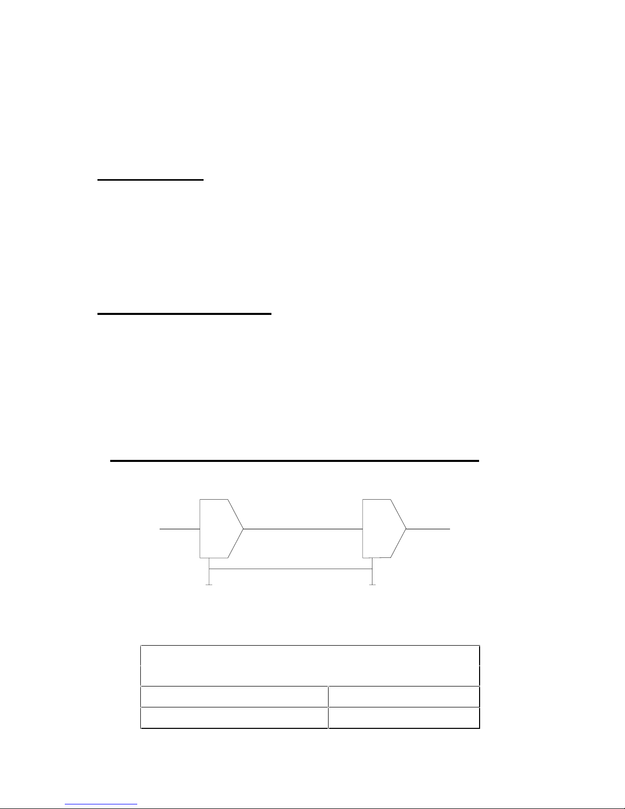
The RS232 standard is ancient in computer industry terms.
Introduced in 1962, it is now widely established. RS232 is a slow
photon, short distance, single ended transmission system (i.e. only
one wire per signal). Typical RS232 maximum cable length is 50
feet with a maximum data rate of 20K bits per second.
Figure 4-1. RS232 Point To Point Connection.
RS232C Standard
1 Driver 1 Receiver
Line Length Max Data Rate
50 Feet = 15m 20 Kbits/sec
DTTL
Ground Ground
TTLR
Page 40
PCI Photon 8 Port RS232 Index
Chapter 4 Page 40
Serial Port Pin Outs.
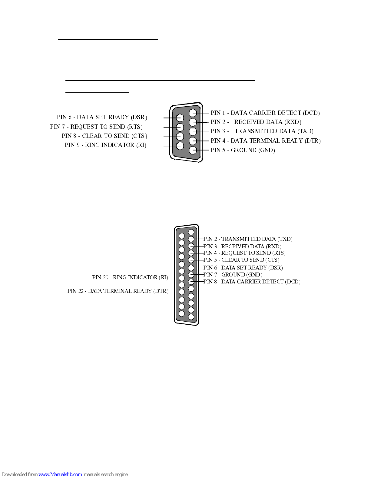
The pinouts of the 9 & 25 pin Male D connectors are given below.
Figure 5-2. Serial Port RS232 Pin Outs.
9 Pin connector:
25 Pin connector:
9 Pin D Serial Port RS232 Cables.
To connect to the AT style RS232 Serial Por t you will need a
cable terminating in a 9 way female D connector. It is sound
practice to use cables with screws fitted that will allow you to
fasten the cable secur ely to th e P C card.
In general, you will need to make up a "cross over" cable to
correctly interface the PC to the RS232 port of another computer
or device. Traditionally, making up the cross over cable has been
considered a black art. However, provided you have the pin outs
4-2 (%8%'%66-)6 ()8)'8('(
4 -2 (%8 % 7 )86)%(=(76
4-2 '0)%6837 )2('87
4 -2 86%27 1- 88) ( (%8% 8<(
4 -2 6 ) ' )-:)( (%8% 6<(
4 -2 (%8% 8 )6 1-2%0 6 )%(= (8 6
4-26)59)78837)2(687
4-26-2+-2(-'%8366-
4 -2 +6 392( +2(
4-2+6392(+2(
4- 2 86 %27 1- 88)( (%8%8< (
4- 2 6 )' )-: )( (%8%6 <(
4-2
6)59)78837)2(687
4-2(% 8 %7)86)%(=(76
4-2'0)%68 37)2('87
4-2
(% 8 %'%66-)6()8)'8('(
4-26-2+-2(-'%8366-
4-2(%8%8 )61-2%06)%(=(86
Page 41

PCI Photon 8 Port RS232 Index
Chapter 4 Page 41
and handshake requirements of both sides of your RS232
connection, the cross over cable becomes a matter of common
sense. The cross over cable is simply to ensure that the right
signals going out of one RS232 port go into the appropriate lines
of the other RS232 port.
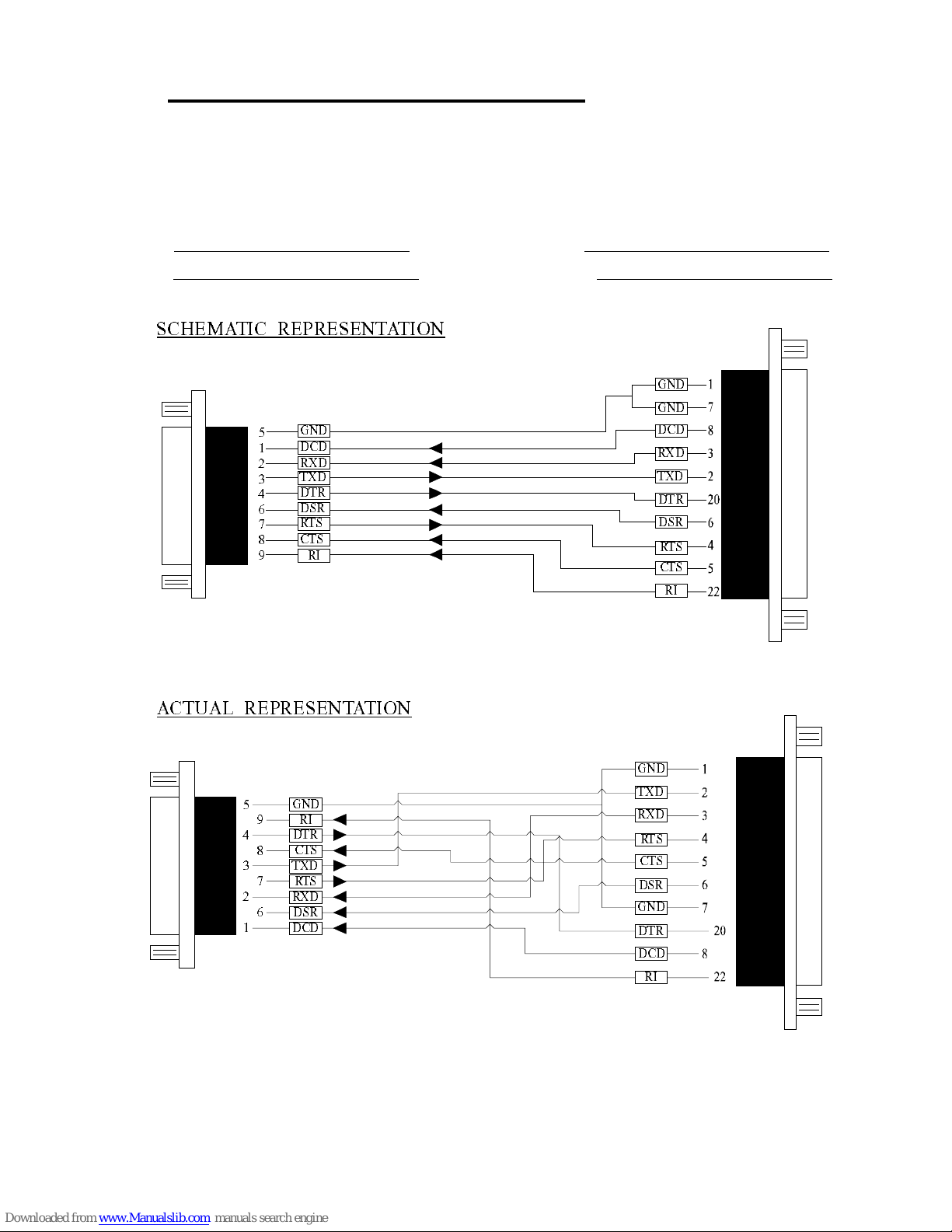
9 Pin D Serial Port Connection To Another PC.
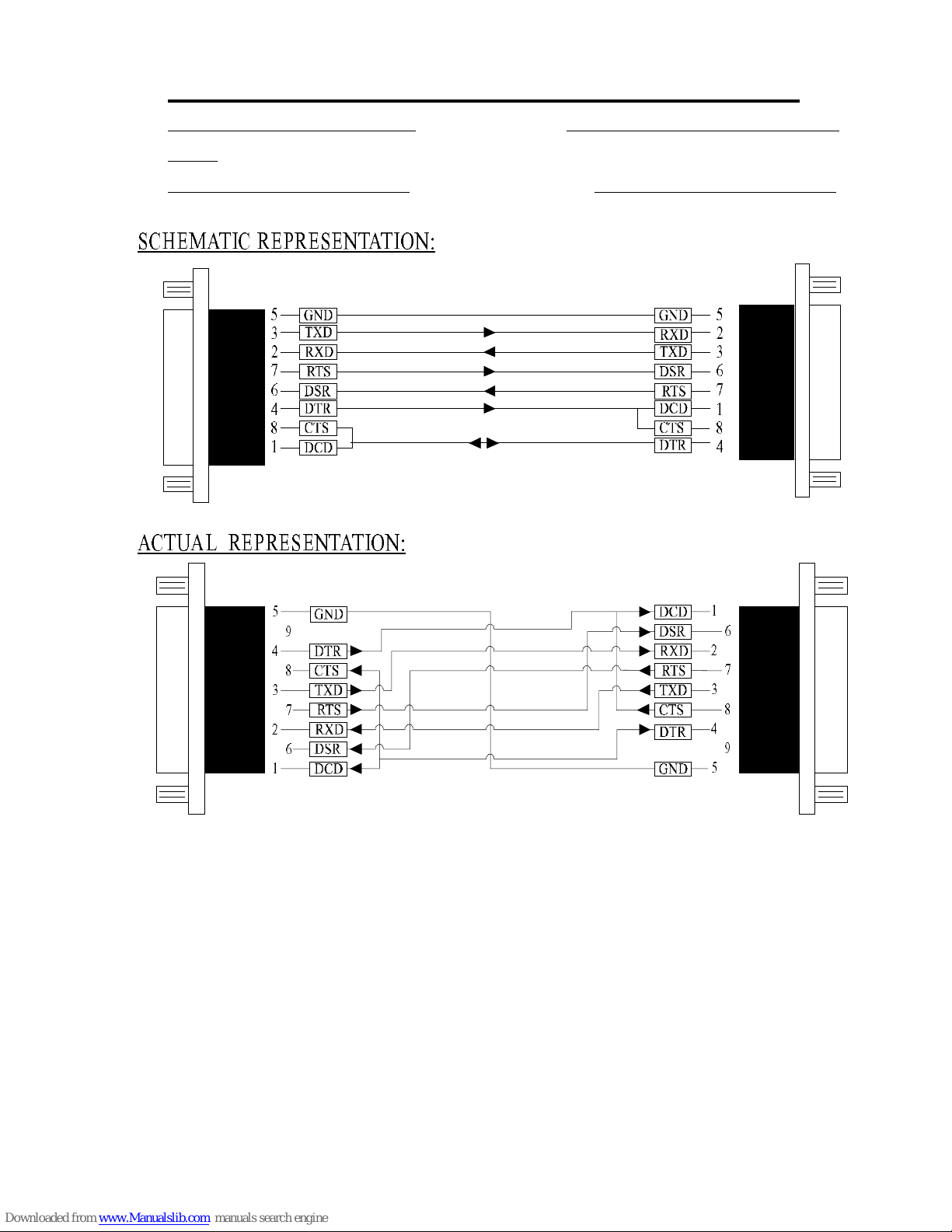
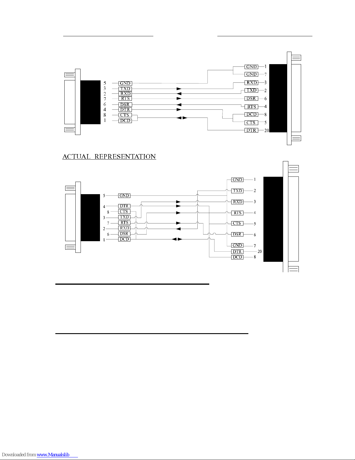
Suppose we want to connect the AT style 9 pin D Serial Port
to the serial port of another IBM PC 25 pin D. See Figure 6-3.
1) Connect the eart h l ines.
Line 5 of Serial Port 2 to lines 1 & 7 of the other PC.
This gives the two devices a common earth level.
2) Connect the T ransmit and Receive lines together.
Line 3, TXD, Por t 2 goes to line 3, RXD, of the other PC.
Line 2, RXD, Port 2 goes to line 2, T XD, of the other PC.
This allows each to receive the data transmitted by the
other.
3) Connect the Port 2 DTR line, pin 4 to the other PC DCD,
pin 8 and CTS, pin 5, lines.
Also, connect up the other PC DTR line, pin 20 to the Port
2 DCD, pin 1 and CTS, pin 8, lines.
This allows the receiving device to signal when it can no
longer accept data. The receiving device sets DTR false
when it is unable to receive any more data. The sending
device reads DTR on its CTS and DCD pins. It should stop
sending when CTS goes false.
4) Connect the Port 2 RTS line, pin 7, to the other PC DSR
line, pin 6.
Also, connect the other PC RTS line, pin 4, to the Port 2
DSR line, pin 6. This RTS line is used to let the other
device know that it is ready for data exchange.
Page 42
PCI Photon 8 Port RS232 Index
Chapter 4 Page 42
Figure 4-3. 9 Pin D Serial Port To Other PC Cable.
AT SERIAL PORT Side Other PC SERIAL PORT
Side.
9 PIN D CONNECTOR 9 PIN D CONNECTOR
%'89%06)46)7)28%8-32
7',)1%8-'6)46)7)28%8-32
Page 43
PCI Photon 8 Port RS232 Index
Chapter 4 Page 43
9 PIN D CONNECTOR 25 PIN D CONNECTOR
9 Pin D Serial Port To A Modem.
If you are connecting a MODEM to a 9 pin D Serial Port
then you will NOT need a cross over cable and a straight through
cable connected as the 9 to 25 pin adapter given in Figure 4-5.
9 Pin D Serial Port Loop Back Connector.
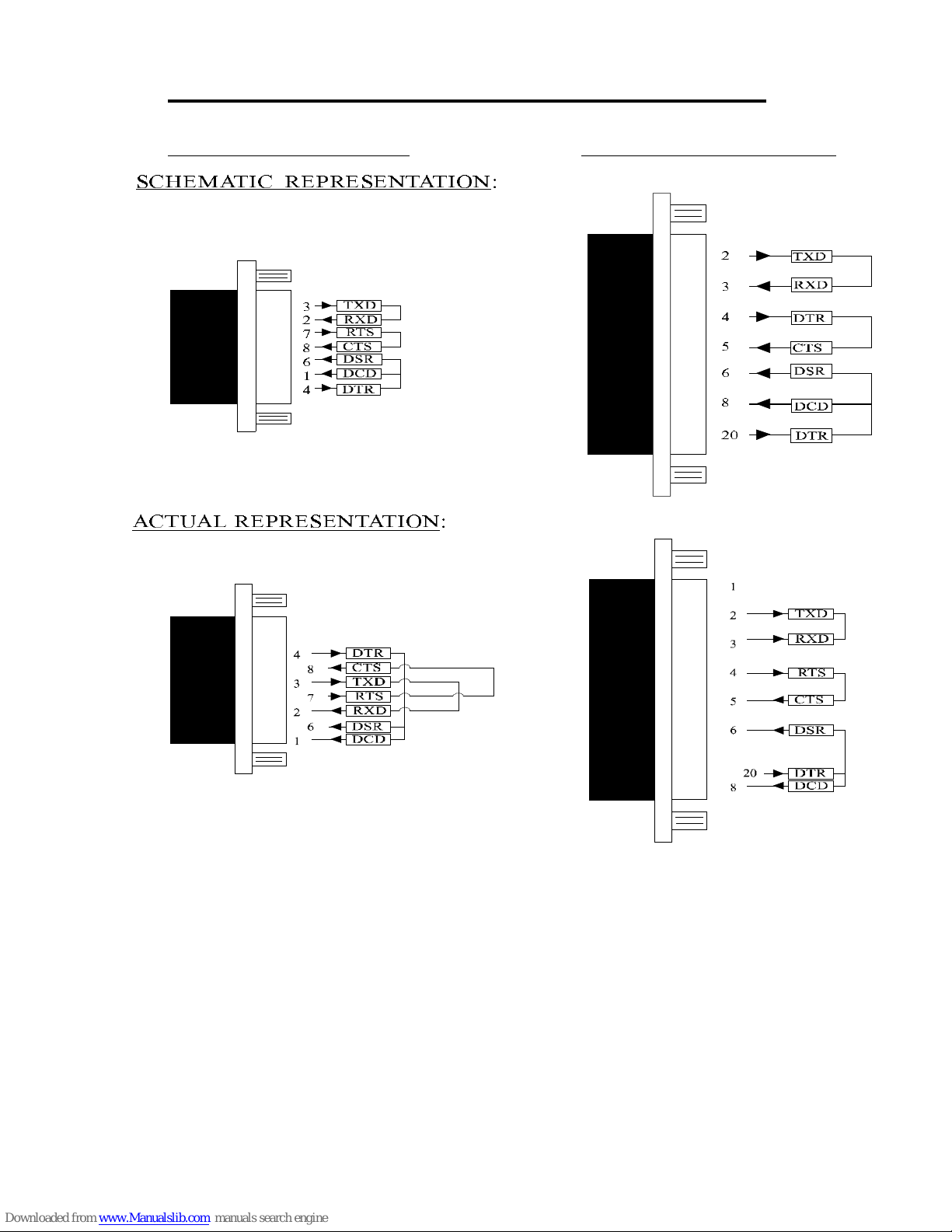
A loop back connector can be used to echo RS232 data
transmitted by a serial port back into its own RS232 receiver. In
this way, the function of the serial port can be tested.
For an AT styl e Serial Po r t use the a f em ale 9 way connector
wired as in Figure 4-4.
%'89%06)46)7)28%8-32
Page 44
PCI Photon 8 Port RS232 Index
Chapter 4 Page 44
Figure 4-4. 9 Pin D Serial Loop Back Connector.
9 PIN D CONNECTOR 25 PIN D CONNECTOR
7',)1%8-'6)46)7)28%8-32
%'89%06)46)7)28%8-32
Page 45
PCI Photon 8 Port RS232 Index
Chapter 4 Page 45
Figure 6-5. 9 To 25 Way Adapter.
This adapter cable makes the AT style 9 pin serial port,
look like the standard PC 25 pin serial port. It is NOT a cross over
cable!
9 Pin AT SERIAL PORT 25 Pin PC SERIAL PORT
9 Pin Female D Connector 25 Pin Male D Connector
%'89%06)46)7)28%8-32
7',)1%8-'6)46)7)28%8-32
+2(
+2(
+2(
(86
(86
8<(
8<(
(76
(76
687
687
6<(
6<(
6-
6-
('(
('(
'87
'87
+2(
(86
8<(
(76
687
6<(
6-
'87
('(
+2(
+2(
8<(
(86
6-
'87
6<(
687
(76
('(
Page 46
PCI Photon 8 Port RS232 Index
Chapter 4 Page 46
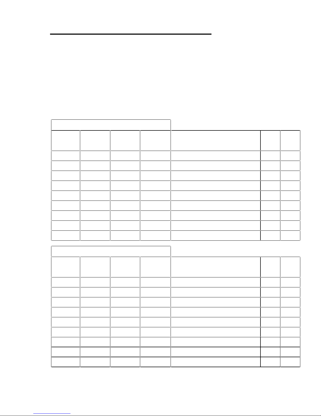
The Lynx Card Octopus Cable Pinouts
The Lynx card octopus cable connects a 78 pin Male D
connector to 8 nine way Male D connectors. Each of the cables has
9 cores plus a sheath. The sheath each of the 25 way D connectors
is connected to the sheath of the 78 way D connector. Each of the
9 pin D connectors has 9 connections in the standard PC serial port
configuration, see figure 7-8, below. Each cable is approximately
1 metre long and is clearly marked as P1 for Por t 1, P2 for Port 2
etc.
78 way D connector Pinouts
Port
#1
Port
#2
Port
#3
Port
#4
Pin Function 9
Pin25Pin
30 50 11 10 Transmitted Data (TXD) 3 2
55 17 37 56 R ecei v ed Dat a (R XD) 2 3
51 31 12 14 Request To Send (RTS) 7 4
16 53 59 57 Clear To Send (CTS) 8 5
54 34 58 38 Data Set Ready (DSR) 6 6
68 69 70 71 Ground (GND) 5 7
35 33 39 18
Data Carrier Detect (DCD)
18
49 32 13 52
Data terminal Ready(DTR)
420
36 15 20 19 Ring Indicator (RI) 9 22
78 way D connector Pinouts
Port
#5
Port
#6
Port
#7
Port
#8
Pin Function 9
Pin25Pin
40 2 63 64 Transmitted Data (TXD) 3 2
28 8 46 27 R ecei ved Dat a (R XD) 2 3
21 41 62 60 Request To Send (RTS) 7 4
25 4 9 45 Clear To Send (CTS) 8 5
5 42 29 26 Data S et R ead y (DS R) 6 6
72 73 74 75 Ground (GND) 5 7
43 23 48 6
Data Carrier Detect (DCD)
18
22 3 61 1
Data terminal Ready(DTR)
420
44 24 47 7 Ring Indicator (RI) 9 22
NOTE: Pins 65,66,75 - 78 on the above connector are not used
Page 47
PCI Photon 8 Port RS232 Index
Chapter 4 Page 47
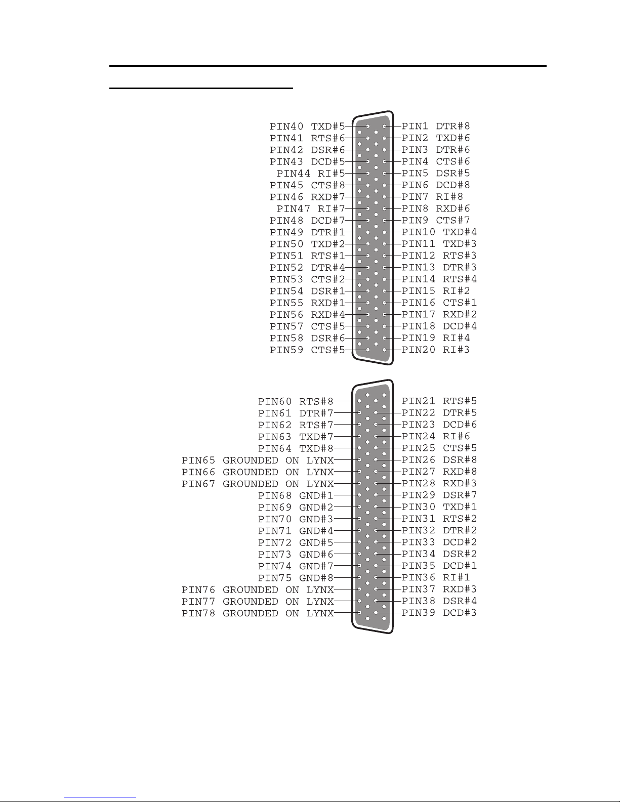
Figure 6-6. Pin Outs of the 78 pin D connector on the
AT Lynx 8 Port RS232
NOTE: On the above diagram the # symbol f ollowed by a number
is used to notify a port on the cable e.g. #4 means port 4, hence
PIN47 DTR#4 is pin 47 of the 78way connector, which
corresponds to the DTR function on port 4.
Page 48

PCI Photon 8 Port RS232 Index
Page 48
16450 / 16550..............................................................................6
2500 .............................................................................................2
adapter................................................................................. 43, 45
asynchronous ...............................................................................6
baud / baud rate............................................................................6
BBCARDS.EXE ........................................................................ 11
bits.........................................................................................8, 39
buffer...........................................................................................6
buffered .......................................................................................6
cable ..................................................................... 8, 39, 40, 43, 45
Changing COM numbers in Windows 95................................... 28
connectors...............................................................................9, 40
cross over ....................................................................... 40, 43, 45
CTS .......................................................................................6, 41
DCD...................................................................................... 6, 41
DSR....................................................................................... 6, 41
DTR....................................................................................... 6, 41
FIFO............................................................................................6
handshake.................................................................................. 41
installation ...................................................................................8
Installing Ports In Microsoft Windows NT 4.0...........................33
Installing Ports In Windows 3.x.................................................11
Installing Ports In Windows 95 & 98. ........................................ 25
loop back ............................................................................. 39, 43
Maximum Baud Rate................................................................. 30
modem.........................................................................................6
PCI Quad RS232 Specifications ...................................................7
pin outs................................................................................ 39, 40
port / ports ......................................6, 8, 25, 33, 39, 40, 41, 43, 45
receive ....................................................................................... 41
RI.................................................................................................6
RS232.....................................................................6, 8, 39, 40, 43
Index
Page 49

Photon 8 Port RS232 Index
RTS .......................................................................................6, 41
RXD...................................................................................... 6, 41
serial port..............................................6, 8, 25, 33, 39, 41, 43, 45
SISR..........................................................................................12
speed............................................................................................6
stop bits........................................................................................8
TXD.......................................................................................6, 41
Uninstalling Serial Solutions PCI for Windows NT....................38
Windows...................................................................... 2, 4, 25, 33
 Loading...