

Page 1

Hardware Manual
¤
¤
¤¤
LPT & RS232
1.1 Edition September 1998
Page 2

Guarantee.
FULL 36 MONTHS GUARANTEE.
We guarantee your Serial Port Card for a full 36 months from
purchase, parts and labour, provided it has been used in the
specified manner. In the unlikely event of failure return your
interface to your Dealer, with proof of purchase, who will
determine whether to repair or replace this product with an
equivalent unit.
COPYRIGHT.
COPYRIGHT © 1985-1998.
All rights reserved. No part of this hardware, circuitr y or manual
may be duplicated, copied, transmitted or repr oduced in any way
without the prior written consent of the Manufacturer.
Serial Solutions is supplied to you by
ACKNOWLEDGEMENT S.
IBM, COMPAQ, Hewlett Packard, H.P. and EPSON are
trademarks of the relevant companies. Windows is a trademark of
Microsoft.
Page 3

PCI LPT & RS232 Introduction
Intro 1
PCI LPT & RS232 MANUAL
OUTLINE CONTENTS
Chapter 1 - Optional Serial Solution Software.
Chapter 2 - PCI LPT & RS232 Specifications.
Chapter 3 - PCI LPT & RS232 Software
Configuration Guide.
The Layout Of This Manual
Chapter 1 - Serial Solution Software, is an overview of the
optional, ideal companion software package for our range of serial
port cards. Buy it from your dealer now!
Chapter 2 - PCI LPT & RS232 Specifications, gives
details of the PCI LPT & RS232 specifications, details of how to
install the optional parallel port and shows you how to install your
PCI LPT & RS232 card.
Chapter 3 - PCI LPT & RS232 Software
Configuration Guide
, shows you how to configure your
operating system to successfully allow trouble free operation of
your PCI LPT & RS232 card. Installation procedures are for
Windows 95/98, Windows 3.x and DOS.
Page 4

PCI LPT & RS232 Introduction
Intro 2
CHAPTER 1.................................................................4
SERIAL SOLUTIONS SOFTWARE........................................ 4
Introduction........................................................................... 4
Introducing Serial Solution Software..................................... 4
Serial Solutions For DOS. ..................................................... 5
Serial Solutions For Windows 3.x.......................................... 7
Serial Solutions For Windows 95........................................... 7
Complete Documentation and Technical Backup................... 8
CHAPTER 2.................................................................9
PCI LPT & RS232 SPECIFICATIONS.................................... 9
Introduction........................................................................... 9
PCI LPT & RS232 Card Features.......................................... 9
Configuring The PCI LPT & RS232 Card. .......................... 11
Parallel Printer Port Configuration....................................... 11
Hardware Installation........................................................... 12
Problems!............................................................................ 13
Installing Serial Port 2......................................................... 13
Chapter 3.....................................................................15
PCI LPT AND RS232 SOFTWARE CONFIGURATION
GUIDE................................................................................... 15
Introduction......................................................................... 15
Installing Ports In Microsoft Windows 95 & 98. .................. 15
Card Settings In Windows 95 & 98...................................... 18
Port Settings In Windows 95 & 98....................................... 19
Configuring Ports In Windows 3.x....................................... 22
Determining PCI LPT & RS232 Resources......................... 22
Windows 3.x Software Installation. ..................................... 23
Serial Port Installation. ........................................................ 24
Configuring The COM Ports................................................ 26
Deleting Ports in Windows.................................................. 27
Page 5

PCI LPT & RS232 Introduction
Intro 3
Restarting Windows............................................................. 27
Configuring Ports In DOS. .................................................. 28
Determining PCI LPT & RS232 Resources......................... 28
NEWCOM.SYS Parameters. ............................................... 29
Configuring And Installing NEWCOM.SYS........................ 30
Port Address........................................................................ 30
IRQ, Range.......................................................................... 31
Number Buffer.................................................................... 31
Buffer Size. ......................................................................... 31
Hardware Handshaking........................................................ 31
Modifying Command Line Parameters. ............................... 31
Page 6

PCI LPT & RS232 Serial Solutions
Chapter 1 Page 4
CHAPTER 1
SERIAL SOLUTIONS SOFTWARE.
Introduction.
This chapter is a brief advertisement for the OPTIONAL
Serial Solutions software package; this is purchased
SEPARATELY and is available from YOUR DEALER.
Introducing Serial Solution Software.
The perfect partner for any Serial Port is Serial Solutions
Software! Serial Solutions is a fully featured suite of programs
designed to squeeze the most from PC ser i al com muni cat ions.
Serial Solutions is made up of the following components: -
Serial Solutions for DOS
Serial Solutions for Windows 3.x
Serial Solutions for Windows 95
Serial Solutions for Windows NT
All the Serial Solutions drivers have the following features:
-
• Drivers for PC FIFO UARTs e.g. 16550 as well as the new
improved 32 byte 16650, 64 byte 16750 and 128 byte 16950
UARTs
• Support for any mix of RS232, RS422 and RS485 handshake
schemes.
• Support for wider range of Baud rates and for more than 4 serial ports.
Page 7

PCI LPT & RS232 Serial Solutions
Chapter 1 Page 5
Serial Solutions For DOS.
Serial Solutions for DOS consists of the following
programs: -
NewCOM.sys A device driver, it supports COM1 to COM16,
allowing 16 serial ports to be used under DOS.
It also includes an interrupt handler for
enhanced performance with user definable
buffer sizes. Accessible from all DOS
languages, it is the heart of the Serial Solution.
It has extensive handshaking support,
implementing both hardware handshaking
using any combination of the DTR, DSR, CTS,
RTS, and DCD lines, and a software handshake
using the XON/XOFF protocol.
NewCOM24.sys A device driver providing support for 24 ports.
NewCOM32.sys A device driver providing support for 32 ports.
NewMode.exe A replacement for the DOS ’mode com...’
command. NewMode is used to set the serial
parameters, including the port address, IRQ
line used, the baud rate, parity and data and
stop bit options.
e.g. NEWMODE COM5:38400,E, 7,1 01A0 7
Baud rates supported are from 110 baud to
115,200 baud! Included is a very handy query
mode that reports the settings of the various
serial ports. Flexible and fast!
EASY programs. The EASY disk contains short, simple to
understand and use EASYBAS, EASYC and
ASYPAS programs, providing straight
forward, file type I /O to serial ports with debug
information. Use these FIRST, base your
sample applications on them.
Page 8

PCI LPT & RS232 Serial Solutions
Chapter 1 Page 6
Source code, make files and compiled r eady to
run programs supplied.
TERM programs A suite of larger terminal
emulation programs written in C (Cterm),
Assembly language (Aterm), Pascal (Pasterm),
BASIC (BASterm) and FORTRAN (FORterm)
show how to access the NE WBIOS routi nes as
well as the simple file I/O to ports. They
contain many lines of code and are thus har der
to grasp. They demonstrate in depth serial port
programming in a variety of languages but they
are also useful tools for using serial devices.
Comtest.exe Comtest is a short but invaluable program that is
used to check that the serial port at a particular
I/O address is functioning correctly and is
connected to the particular I RQ line. T h e progr am
correctly identifies the UART type e.g. non-
FIFO, 16550 FIFO, 16550AF FIFO and the
improved 16650 32 byte FIFO and 16750 64 byte
FIFO’s. By employing the built in loop back
capability of the PC serial port chip, a full test of
the baud rate generator, transmitting and receiving
buffer, parity enable and start stop bit is
performed. There is no need for a second serial
port or a cable when using this utility.
Page 9

PCI LPT & RS232 Serial Solutions
Chapter 1 Page 7
Serial Solutions For Windows 3.x
Serial Solutions for Windows 3.x works with Windows
3.0, 3.1 and 3. 11 as well as Windows For Workgroups 3.11.
Serial Solutions for Windows 3.x consists of the following
programs: Setup.exe T he i nst all r outi ne f or t he package.
Port.DLL Enhanced Control Panel applet. Allows
configuration of extra serial ports from the
Windows Control Panel. Supports single as well
as multiport cards using shared interrupts.
BbLynx.drv Replacement for COMM.DRV.
LynxAPI.dll Enhancement to the Windows Comms API’s
allowing support for more than 9 ports.
Term.exe Terminal program.
EasyCWIN C source code, project files and ready to r un.exe
program for an easy to understand Windows
terminal program. Learn how to write Windows
comms apps correctly th e easy way.
Serial Solutions For Windows 95.
Windows 95 has an improved communication API and
directly supports up to 255 ports. Our Windows 95 driver supports
the shared interrupt mechanism used on our multiport cards. Serial
Solutions for Windows 95 consists of the following programs: -
ISA.inf
PCI.inf
SSDRVS.INF
SSCARDUI.DLL
SSPORTUI.DLL
SSSENUM.vxd
SSM485.VXD
SSMULT.VXD
SSV485.VXD
SSVEL.VXD
The information files to aid the installation
process "Have Disk.. .
…The DLL ’ s and…
...the virtual device driver providing the
shared interrupt handler.
Page 10

PCI LPT & RS232 Serial Solutions
Chapter 1 Page 8
Complete Document ation a nd T ec hnic al Ba ckup .
We believe in supplying complete documentation with
every package we sell. T he Serial Solution S oftwar e Package is no
exception, it has an attractive manual in an A5 binder, containing
over 150 pages of in-depth technical detail with comprehensive
indexes and table of contents. We guarantee your Serial Solution
Software package or a f ull 12 months from purchase. A complete
technical backup service is available to ensure that you get the
maximum performance out of your investment.
Page 11

PCI LPT & RS232 Specifications
Chapter 2 Page 9
CHAPTER 2
PCI LPT & RS232
SPECIFICATIONS
Introduction.
This chapter details the specifications of the PCI LPT &
RS232 card and explains how to add the optional serial port to the
card.
This half-sized card will work happily in any PCI 2.0 or
greater compliant PC compatible.
PCI LPT & RS232 Card Fe atures.
• Centronics Parallel printer port, 100% PC compatible
• One or Two independent 9 pin D RS232 Serial ports.
• Reliable communications up to 50 feet, 15m, and beyond!
• 16550 FIFO provides 16-byte input and 16-byte output buffer
on each port.
• Maximum baud rate of 115,200 Baud.
• Word length of 5, 6, 7 or 8 bits.
• Even, Odd, None, Mar k or S pace par it y opti ons.
• 1 start bit always sent.
• 1, (1.5 for 5 bit data wor d length) or 2 stop bits.
• Clock input of 1.8432 MHz
• 100% PC Compatible serial port TI 16C550, up to 115,200
baud.
• Full modem control TXD, RXD, DSR, DCD, DT R, RTS, CT S
and RI signals.
• Fully double buffered for reliable asynchronous operation.
• High-speed integrated circuitry ensures operation with fast PC’s
e.g. 500MHz Pentium II WIT HOUT extr a wait states.
Page 12
PCI LPT & RS232 Specifications
Chapter 2 Page 10
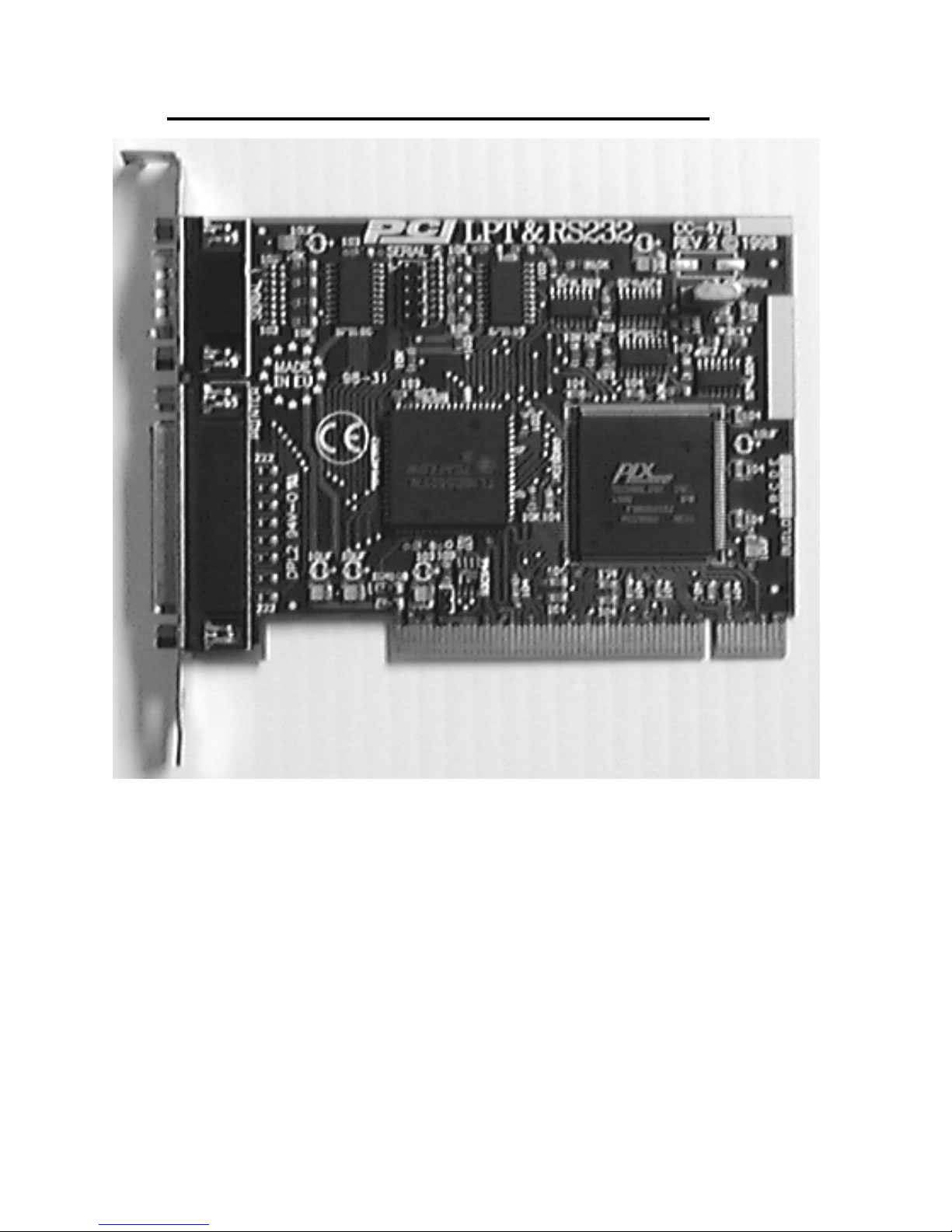
Figure 2-1. PCI LPT & RS232 Card Layout.
PCI LPT & RS232 Specifications:
Dimensions: 4.8 x 3.5 in, 120 x 90 mm
I/O Connection: Serial Por t 1: 9 pin Male D type.
Optional Serial Port 2: 9 pin Male D type.
(via flylead with P C bracket . )
LPT port: Parallel Port: 25 pin Female D type
Page 13
PCI LPT & RS232 Specifications
Chapter 2 Page 11
Configuring The PCI LPT & RS232 Card.
PCI cards, by definition, require no hardwar e conf igur ation
and can be installed "directly from the box".
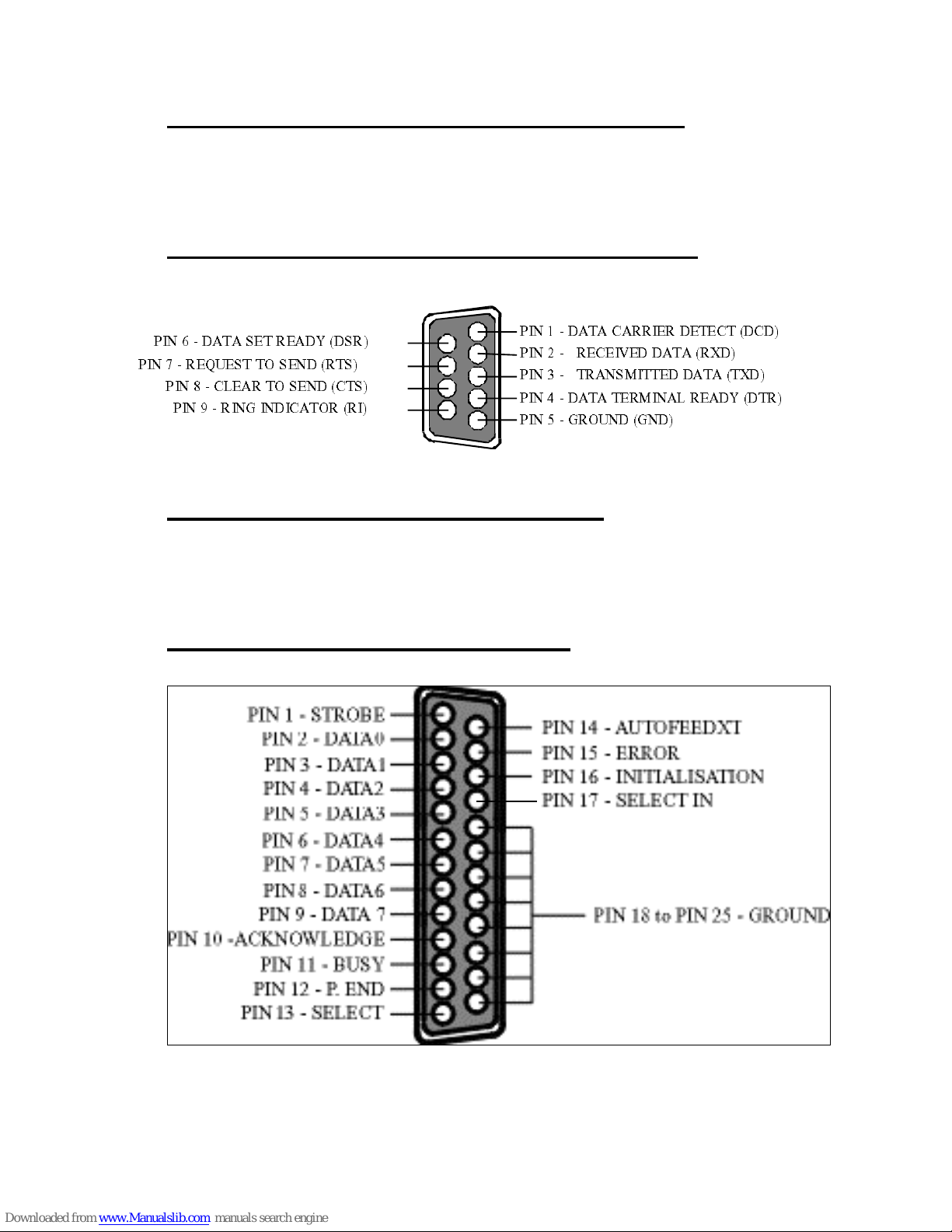
Figure 2-2. 9 Pin D Connector Port Pinouts.
Parallel P r inter Port Configuration.
On the PCI LPT & RS232 card, the par allel printer port is
the lower 25-pin connector on the card.
Figure 2-3 Printer Port Pin Outs.
4-2(%8%'%66-)6()8)'8('(
4-2(%8%7)86)%(=(76
4-2'0)%6837)2('87
4-2 86%271-88)((%8%8<(
4-2 6)')-:)( (%8%6<(
4-2(%8%8)61-2%06)%(=(86
4-26)59)78837)2(687
4-26-2+-2(-'%8366-
4-2+6392(+2(
Page 14
PCI LPT & RS232 Specifications
Chapter 2 Page 12
Hardware Installation.
NOTE: Always turn the computer OFF before installing or
removing any interface board. . ! ! !
STEP 1: Before the PC card can be installed the power to the PC
must be switched off and for additional safety it is recommended
that the mains supply plug is removed from the PC itself.
STEP 2: Remove t he case.
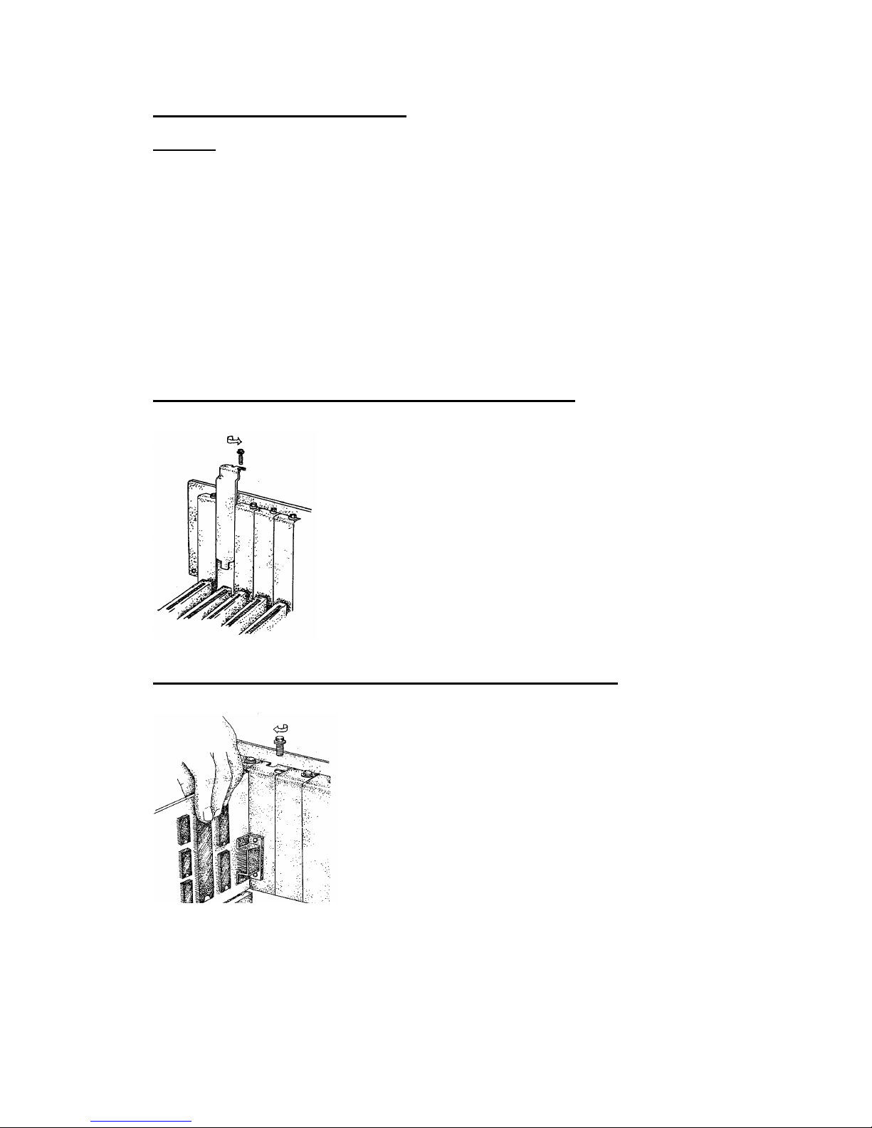
Figure 2-4. Removing Blanking Cover
STEP 3: Choose an empty appropriate
expansion slot. Remove the blanking cover
protecting the slot on the PC back panel.
KEEP the blanking cover screw safely for
later (Figure 2-4) .
Figure 2-5. Inserting The PC Serial Card.
STEP 4: Now insert the PC Serial card in
the available slot. Be careful to ensure that
the gold plated PCB fingers fits neatly into
the I/O expansion connector. Press down
firmly but evenly on the top of the PC Serial
card (Figure 2-5) .
STEP 5: The D connectors should fit neatly thr ough the slot’s aperture to
the outside world. NB. Use the screw kept back fr om the blanking cover
to screw the PC Serial retaining bracket into the PC back panel housing.
Page 15

PCI LPT & RS232 Specifications
Chapter 2 Page 13
STEP 6: Now replace the system units cover by carefully sliding
it down and back over the system unit. Replace the cover
mounting screws.
STEP 7: After attaching all the monitor and keyboard cables,
power up the PC. Do not fo rg et th e mains power cabl e!
The PC should power on in the normal way.
Problems!
If the system fails to power up normally check the following.:
i.) Ensure that the PC S er ial car d is inst all ed cor r ectl y.
ii.) Ensure that other cards in the PC have not been upset.
iii.) Ensure that the power is connected and the PC is switched
ON!
n
If all these have been checked and the PC still does not
power up then there is probably a conflict of I/O address between
the PC Serial card and another board in the PC. Ask your dealer to
check this
Installing Serial Port 2.
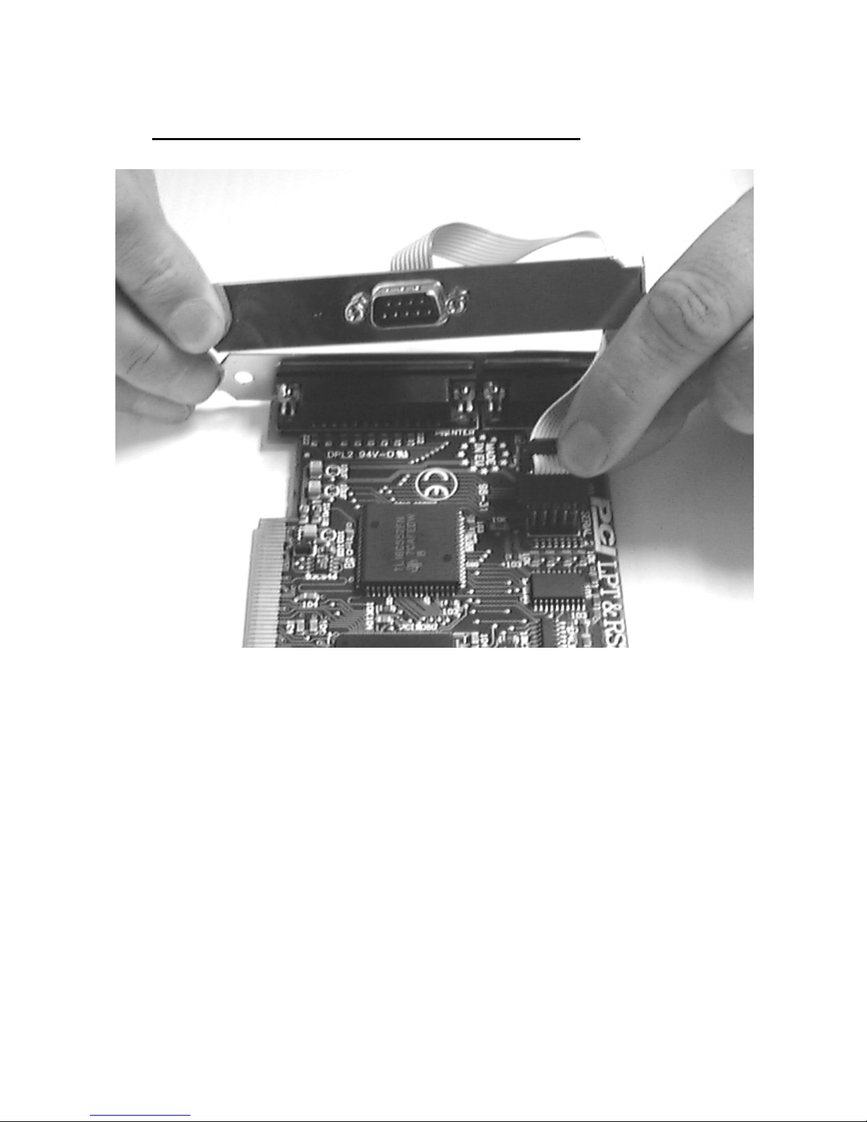
On the ribbon cable of the fly lead, an individual wire is
coloured, which leads to the male connector, at which point it
terminates, below that point is an inverted triangle - this indicates
the Pin # 1 of the serial port. Making sure the Pin # 1 marking on
the plug aligns with the Pin # 1 marking next to the serial header
press the plug down evenly and firmly, until resistance is felt - the
serial port has been plugged in. It is then mounted on a bracket
allowing it be placed in a spare PC aperture. Figure 2-6, below,
indicates this.
Page 16
PCI LPT & RS232 Specifications
Chapter 2 Page 14
Figure 2-6 Installation of Serial Port 2.
Page 17

PCI LPT & RS232 Software Guide
Chapter 3 Page 15
Chapter 3
PCI LPT AND RS232 SOFTWARE
CONFIGURATION GUIDE
Introduction.
This section contains the installation procedures of the PCI L PT
and RS232 card, with the Windows 95/98 Windows 3.x and DOS
operating systems.
The setup procedures in this chapter assume that your PC has
only one serial port present.
Installing Ports In Microsoft Windows 95 & 98.
Although covering the installation of the PCI LPT and RS232
into the Windows 95 operating system, the procedure is also valid, with
only minor differences, in the Windows 98 Operating System. The
Windows 95 environment now supports up to 255 standard serial ports,
RS232, RS422, RS485 etc.
To obtain a trouble free mix- and-match of the COM ports:
• Switch off your computer, insert your PCI LPT and RS232 card
into a free PCI slot, as described in the section "Hardware
Installation" in Chapter 2, and switch your computer on again.
• During the booting process, Windows 95 will detect PCI LPT and
RS232, but will display it simply as a "PCI CARD", and you will
briefly see a message box to this effect.
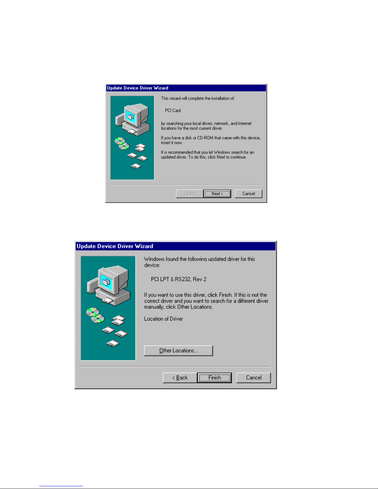
• Windows will then display the "Update Device Driver Wizard",
which asks you to “ insert any disk which came with the PCI card” .
Page 18
PCI LPT & RS232 Software Guide
Chapter 3 Page 16
Insert the Windows 95 installation disk into an appropriate drive and
click ’Next’.
• The Wizard should then display something similar to following:
• Click Finish.
Page 19
PCI LPT & RS232 Software Guide
Chapter 3 Page 17
• A "Copying Files…" window should now appear. Click 'OK' when it
asks you to insert the disk.
• After copying the file, Windows 95 will then detect each of the serial
ports in turn and install them as communications ports; in the case of
the PCI LPT and RS232 it will also detect the parallel port, and then
install it as a printer port.
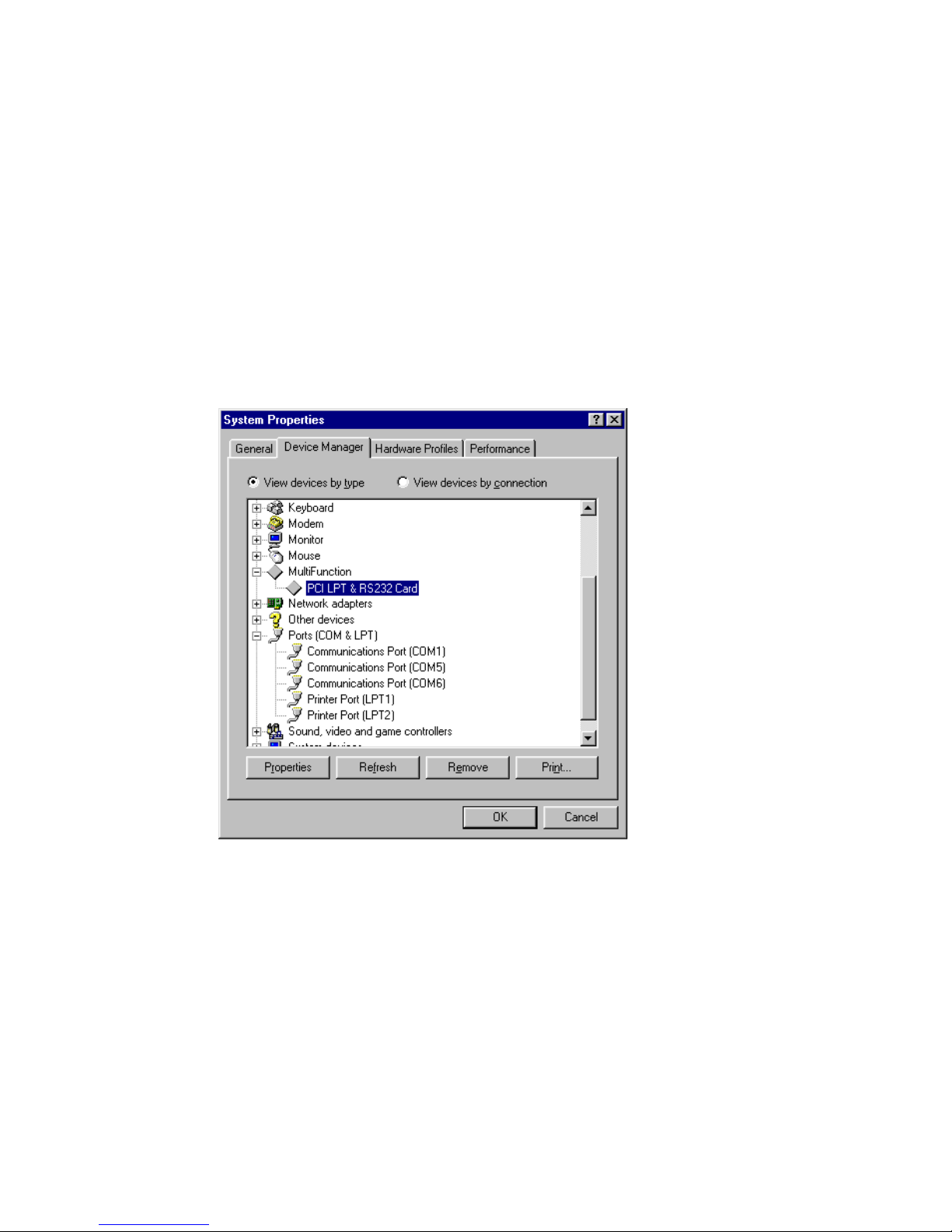
When the "Device Manager" is viewed:
• PCI LPT and RS232 will appear under the "Multi-function
adapters" branch, a Communications Ports and a Printer Port will
appear under the "Ports (COM & LPT) branch."
For most users who have 4 or less COM ports the new ports
will appear as COM5 and COM6, as pictured below; for users with
more than 5 COM ports the new ports will appear as the first available
COM ports.
Page 20
PCI LPT & RS232 Software Guide
Chapter 3 Page 18
Card Settings In Windows 95 & 98.
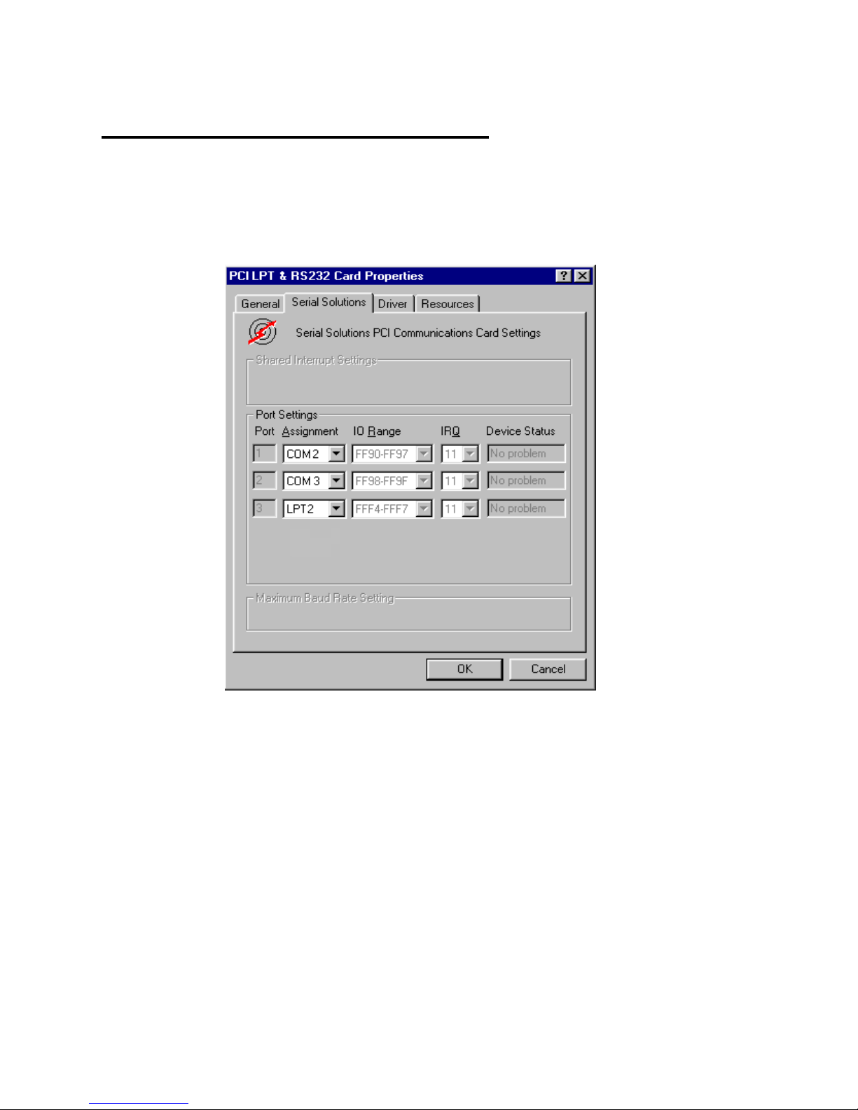
• Select the PCI LPT and RS232 card from the "Multi-Function
Adapter" entry in Device Manager and click on properties to view
the cards general properties; clicking on the Serial Solutions tab
produces:
In this window, the COM (and LPT) port assignment may be changed,
simply by selecting a new COM port value from the pull down menu
relevant to the port. However, COM port usage other than those for the
PCI LPT and RS232 card itself are not checked, so it is advisable to first
check which COM ports are in use - port availability can be checked by
viewing the Device Manager.
This process also appli es t o L P T assi gnm ent, and LPT por t usage can al so
be viewed from the Device M anager.
. NOTE: At time of print there exists no facility within the driver
software to disable any of the card’s ports.
Page 21
PCI LPT & RS232 Software Guide
Chapter 3 Page 19
Port Settings In Windows 95 & 98.
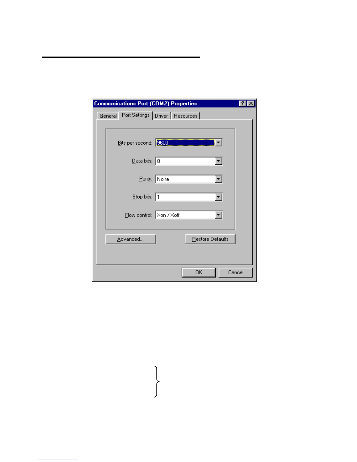
Double clicking on a Communications Port that belongs to a
PCI LPT and RS232 card will display general properties window for
that port (in this case COM2). Selecting the Port Settings tab produces:
Settings available in these windows are:
1. Baud Rate - determines the baud rate at which the selected
port operates.
• the maximum value of operation is 115,200, even though
the maximum value selectable is 921,600 - this is due to
standard Windows COM port drivers being used.
2. Data Bits.
3. Parity.
4. St op B its.
5. Flow Con trol.
Change to suit remote device.
Page 22
PCI LPT & RS232 Software Guide
Chapter 3 Page 20
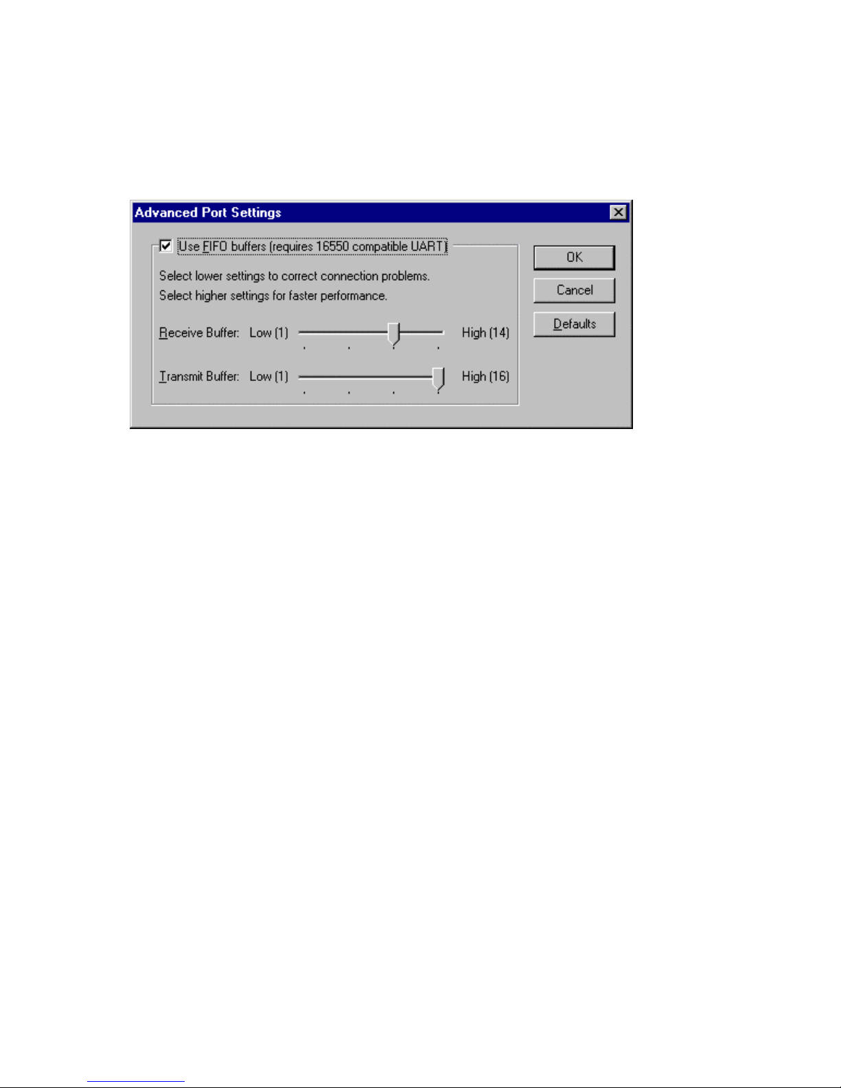
6. Advanced - clicking on this will display the following
window:
Settings available in this window are:
• Use FIFO B u ffers - tur ns the selected por ts F IFO buffer
on or off. It is strongly recommended that the FIFO for
both ports is left enabled.
• Receive Buffer - These settings allow the selection of a
receiver FIFO trigger setting. Selecting a low value will
allow the interrupt to be serviced quicker, which is good
for slow machines. If you have a fast machine, setting a
high value will give you more time for multi-tasking
operations.
• Transmit Buffer - These settings allow the selection of
a transmitter FIFO trigger setting. Selecting a low value
will send fewer data-bytes per interrupt, and this is
recommended if you are communicating to a slower
machine. Selecting a high value will send more databytes per interrupt, and will give more time for multitasking operations.
Page 23

PCI LPT & RS232 Software Guide
Chapter 3 Page 21
• Defaults: when clicked this button restores the advanced
settings for the selected port to:
Use FIFO Buffers: On (Checked)
Receive Buffer: High (14)
Transmit Bu ffe r: High (14)
7. Restore Defaults - when clicked, resets the selected COM
port to the following values:
Baud Rate: 9600
Data Bits: 8
Parity: None
Stop Bits: 1
Flow Control: Xon / Xoff
Page 24

PCI LPT & RS232 Software Guide
Chapter 3 Page 22
Configuring Ports In Windows 3.x
The Windows 3.x installation procedure consists of two steps after the
PCI LPT & RS232 CARD is inserted:
1. Determining the resources that the PCI LPT & RS232 Card has
claimed.
2. Informing Windows 3.x of those resources.
Determining PCI LPT & RS232 Resources.
Insert the car d in to a P C, as descr i bed in Chapt er 2.
Run BBCARDS.EXE, f ro m the supplied DOS utility disk titled "Serial
Solutions Utility Disk" by typing the following:
A:\PCI\BBCARDS
Where A:\ is the drive containing the supplied disk.
BBCARDS.EXE will r eturn a stri ng that looks similar to the following
(values contained in the string may differ in individual PC’s due to
resource availability):
PCI LPT & RS232 users:
card 1 is on bus 0, device 16, function 0
Card ID=5, revision 2: LPT & RS232
interrupt line 11 has been assigned
2 sets of 16550-compatible registers are at I/0 address 0140
Note down IRQ and 1/0 address, which in this case are:
The IRQ = 11
The 1/0 address = 0140
Page 25
PCI LPT & RS232 Software Guide
Chapter 3 Page 23
Windows 3.x Software Installation.
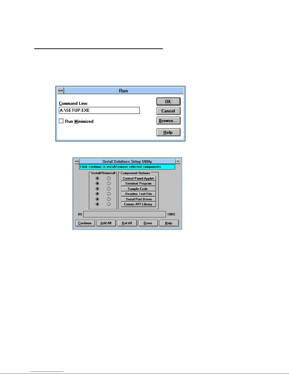
Place the supplied Serial Solutions for Windows 3.x disk in a suitable
drive. From File Manager choose ’Run’ and enter a:\setup (where a:
is the path to the floppy drive with the installation disk).
* Click OK, the Setup Program Main Screen is displayed:
By default, all component options will be installed, selecting the "Del
AT’ button will select all installed components for deletion and "Add
All" chooses all uninstalled components for installation; options may
not be changed when the components are installed. For further details
on the Component Options consult the README.TXT file on the
supplied disk.
If only logical ports COM1 to COM9 are to be used then de-select the
Comms API library option in the "Install" column. This library is only
necessary to allow the use of l ogical por ts gr eater t han COM9 e. g.
COM10 COM11 etc.
Page 26
PCI LPT & RS232 Software Guide
Chapter 3 Page 24
When you have made your choice of Component Options click
Continue and when the setup program has finished select the Done
button.
Note: If th e S er ial P or t dr iv er opt ions has been sel ected, after t he set up
program has finished, Windows will display a restart message - answer
Yes and Serial Solutions will be ready to run upon Windows restarting.
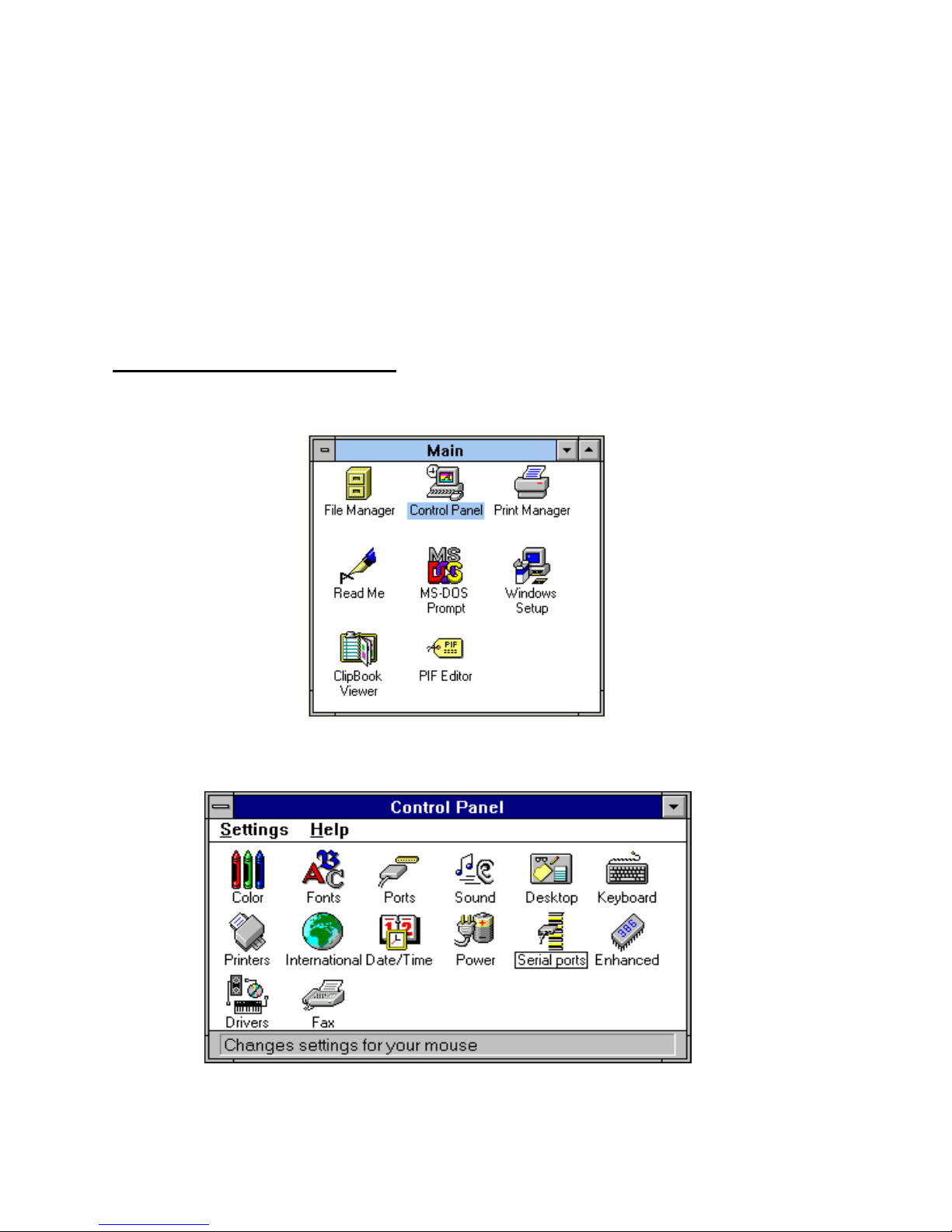
Serial Port Installation.
From Main , sel ect Control Panel:
Click on Seria l P ort s:
The following dialogue will be displayed:
Page 27

PCI LPT & RS232 Software Guide
Chapter 3 Page 25
To add a COM port:
Click on the add button and a Window similar to the following will be
displayed:
In Standard Settings:
In the COM Base field, enter the value 0140.
Note: COM ports are defined with an i/o address range, which in this
case, begins at 0140 and all subsequent ports have an i/o address that is
8 higher than the previous. i.e. if COM2 has an address of 0140h, then
COM3 has an address of 0148h.
In the IRQ field, ent er the val ue 11.
Note: The values used in the above section were those returned by the
BBCARDS program, as described in the above section.
Page 28
PCI LPT & RS232 Software Guide
Chapter 3 Page 26
When you have finished, click on OK. A restart message will be
displayed; to save time restart only when both ports have been added
and correctly configured.
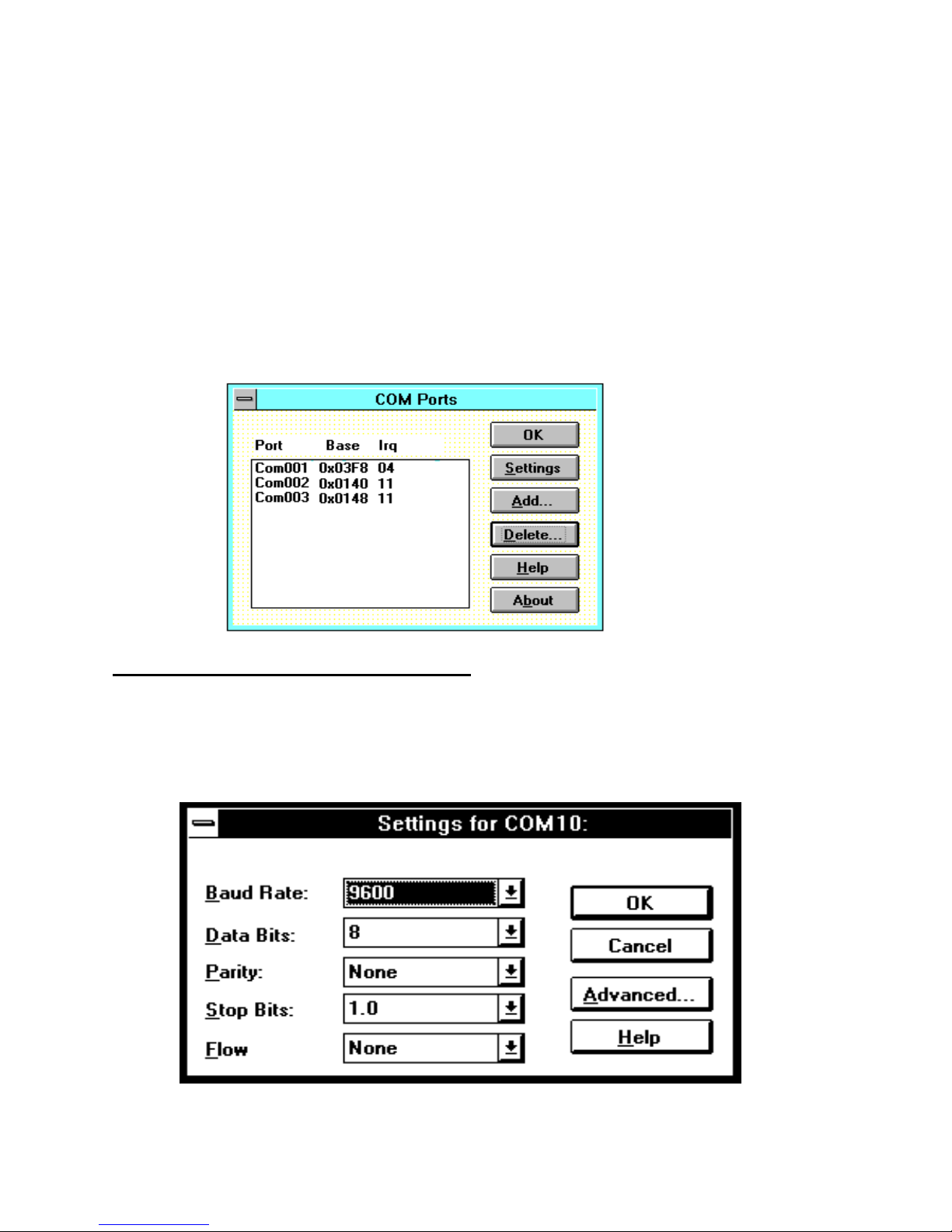
Repeat the above process to add the second COM port of the PCI LPT
& RS232, the COM base will be 0148; the IRQ value will remain the
same. After adding the remaining COM port the COM Ports Window
will look similar to the following:
Configuri ng T he COM Por ts .
From the COM Ports window choose the port that you wish to
configure and click on Settings - the following dialogue will be
displayed:
Page 29

PCI LPT & RS232 Software Guide
Chapter 3 Page 27
Note: A port that has been added has the default values of.
Baud Rate: 9600
Data Bits: 8
Parity: None
top Bits: 1.0
Flow: None
Change the communications Settings in the COM Ports to match
the baud rate, parity settings etc. of the remote serial device.
Deleting Ports in Windows.
The Delete button can be used to discard the entries of ports that
have been removed from the system. Note. Never tr y to leave out
a serial port number when using th e delete but ton, because
Windows may automatically shift serial port numbers which
results in a mismatch of settings in the Serial Ports Applet (COM
1-COM4 only).
Restarting Windows.
Whenever certain values have been enter ed or changed i n the
hardware settings window, a message prompting to restart
Windows will appear. Only after having made ALL the necessary
changes restart Windows so that the new settings come into effect.
Page 30

PCI LPT & RS232 Software Guide
Chapter 3 Page 28
Configuri ng Por ts In DOS.
The DOS installation procedure consists of two steps after the PCI
LPT & RS232 card is inserted:
1. Determining the resources that the PCI LPT & RS232 has
claimed.
2. Informing the Serial Solutions DOS device driver of those
resources.
Determining PCI LPT & RS232 Resources.
Insert card into PC, as described in Chapter 2.
Run BBCARDS.EXE, f ro m the supplied DOS utility disk titled
"Serial Solutions Utility Disk" by typing the following:
A:\PCI\BBCARDS
Where A:\ is the drive containing the supplied disk.
BBCARDS.EXE will r eturn a stri ng that looks similar to the
following (values contained in the string may differ in individual
PC’s due to resource availability):
PCI LPT & RS232 users:
card 1 is on bus 0, device 16, function 0
Card ID=5, revision 2: LPT & RS232
interrupt line 11 has been assigned
2 sets of 16550-compatible registers are at I/0 address
0140
Note down IRQ and 1/0 which in this case:
The IRQ= 11
The 110 address = 0140
Page 31

PCI LPT & RS232 Software Guide
Chapter 3 Page 29
NEWCOM.SYS Parameters.
The NewCOM.SYS device driver included with the PCI LP T &
RS232 driver software is used to set up the card in DOS and has
the following syntax:
PCI LPT & RS232
NEWCOM.SYS /A port address, /I IRQ, range /B number buf fer
/S buffer /H hardware handshake
Where /A port address specifies COM port number followed by a
hexadecimal address in the form /Ax,y where x is COM port range
and y is I/0 address.
A IRQ, range specifies card interr upt and COM port range. T he
COM port range specifies the COM port(s). Range may be a single
port OR a range of ports.
/B number buff er is used to set the number of pairs of buffers to be
allocated to ports and is a decimal number in the range 1-maxport.
/S buffer Set size of all buffers in bytes, buffer is rounded to the
nearest power of 2 and must be a decimal number in the range 32
to 32768. For any serial port opened two buffers of size buffer are
allocated, one for input and the other f or output.
/H hardware handshake selects which hardware handshake type to
use on the specified ports. This is used in the following manner:
/H range, hs where range specifies the COM port or ports and hs
selects handshake type. Handshake types available are:
Type 0 RS232 DTR/CTS - The PC only transmits when
CTS is input true. When the PC is able to receive
its sets DTR output true. The DSR and DCD inputs
Page 32

PCI LPT & RS232 Software Guide
Chapter 3 Page 30
are ignored. The RTS output line is set true just in
case the external ser i al devi ce needs a true signal.
Type 4 3 Wire Handshake - Really no handshake at all
since the PC transmits irrespective of the handshake
lines. The 3 wires are TxD, RxD and Gr ound, no
other lines are required. Thus the CTS, DSR and
DCD inputs are ignored. The RTS and DTR output
lines are set t r ue j ust i n case t he ext er n al serial
device needs a true signal.
Note: If hardware handshaking is not specified in the
NEWCOM.SYS parameters, type 4, 3 Wir e
Handshake is selected automatically.
Configuring And Installing NEWCOM.SYS
To load the Serial So lut ions f or DOS device dr iv er an ent r y needs
to be added to the CONFIG.SYS file. Any simple text editor,
EDIT f or exam ple, can edi t t he CONF I G. S YS f il e f or exampl e.
The installation procedure given below is for a PCI LPT & RS232
as COM 5 - COM6.
The parameter required by the NE WCOM.SYS dr iver ar e those
returned b y t he BBCARDS . EXE appli cati on ear li er . A brief
explanation for the parameters required by NEWCOM.S YS
follows:
Port Address.
/A5-6,0140
COM ports 5 and 6 are defined, with an i/o address range that
begins at 0140h with the next port having an i/o address that is 8
higher than the previous. i.e. COM5 has an address of 0140h,
therefore COM6 will have an address of 0148h.
Page 33

PCI LPT & RS232 Software Guide
Chapter 3 Page 31
IRQ, Range.
/I 11,5-6
11 is the IRQ and since the COM port range is COM5 COM6
range is entered as 5-6.
Number Buffer.
/B6
Six buffers are defined, though only four por ts are in use this is
because buffers in DOS ar e assi gned in a sequent ial or der f r om
COM1. Since the PG LPT & RS232 has been assigned COM port
values of 5 to 6, all pr ecedi ng COM por ts, must have buf f er s
assigned to them also.
Buffer Size.
/S512
Buffer size set to 512 bytes.
Hardware Handshaking.
/H,4
Type 4, 3 Wire Handshake selected for all ports. T ype 4, 3 Wir e
Handshake selected for all ports.
Modifying Command Line Parameters.
When "assembled" the NEWCOM.SYS command line looks like...
DEVICE=NEWCOM.SYS /A5-6,0140 A 11,5- 6 /B8 /S 512 /H,4
... and should be entered into the CONFIG.SYS file. Once you are
sure that these parameters have been entered correctly, restart your
PC and your PCI LPT & RS232 should be ready to use
immediately.
Sample terminal applications are provided on "Serial Solutions
Disk 1 & 2" enabling communications to be established to your
peripherals quickly and easily.
Page 34

INDEX
16450 / 16550......................................................................4, 6, 9
asynchronous ...............................................................................9
baud / baud rate.................................................................... 5, 6, 9
buffer / buffered................................................................... 5, 6, 9
cable....................................................................................... 6, 13
Changing COM numbers in Windows 95...................................19
command .....................................................................................5
Configuring ports in Windows 95 & 98......................................20
connectors...................................................................................12
CTS .........................................................................................5, 9
data word length...........................................................................9
DCD........................................................................................5, 9
DSR......................................................................................... 5, 9
DTR......................................................................................... 5, 9
emulation.....................................................................................6
FIFO.................................................................................... 4, 6, 9
handshake................................................................................ 4, 5
installation ................................................................................. 16
Installing Ports In Windows 95 & 98. ........................................ 16
interrupts......................................................................................7
loop back...................................................................................... 6
mode ............................................................................................5
modem .........................................................................................9
Optional Serial / Parallel Port ..................................................... 10
Parallel Printer Port....................................................................11
parity ....................................................................................... 5, 6
port.......................................................................................... 5, 6
port / ports ..............................................................1, 9, 10, 11, 16
ports...................................................................................4, 5, 6, 7
Print / Printer.........................................................................9, 11
protocol........................................................................................5
RI.................................................................................................9
RS232.......................................................................1, 4, 9, 10, 11
Index
Page 35

INDEX
RS422 / RS485 ............................................................................4
RTS .........................................................................................5, 9
RXD............................................................................................9
serial port..................................................................1, 4, 5, 6, 7, 9
shared interrupt............................................................................7
speed............................................................................................9
technical.......................................................................................8
TXD.............................................................................................9
Windows...................................................................... 2, 4, 6, 4, 7
 Loading...