

Page 1
INSTRUCTION
MANUAL
BRAILLO
200
BRAILLO M NORWAY
FOR BETTER BRAILLE - AND MORE
Rev. 9705
Page 2

Page 3

BRAILLO M NORWAY AS B 200
TABLE OF CONTENTS
1. INSTALLATION ....................................................1
1.1 Requirements of Installation Site ........................................1
1.2 Unpacking ........................................................1
1.3 Removal of Covers ..................................................2
1.4 Interfacing to Computer ...............................................4
2. OPERATING .......................................................7
2.1 Operating Panel .....................................................7
2.2 Current Values and Options ...........................................12
2.3 Print Values .......................................................13
2.4 Messages/Error Messages ............................................15
2.5 Inserting Paper .....................................................18
2.6 Test Print .........................................................19
2.7 Escape-Sequences ..................................................20
2.8 Lines per Page, Example: .............................................27
3. SERVICE AND MAINTENANCE .....................................28
3.1 Troubleshooting ....................................................28
3.2 Principal Design of Printing Procedure ...................................30
3.3 Table of Page Sequences .............................................32
3.4 Magnet Rack, Removal and Refitting ....................................33
3.5 Magnet Rack, Disassembly, Assembly and Adjusting ........................34
3.6 Magnet Rack, Figures ...............................................35
3.7 Magnet Rack, Printing Process ........................................37
3.8 How to Replace Short Pivot Arms ......................................38
3.9 Return Springs, Adjustment ...........................................40
3.10 Eccentrics, Adjustment ..............................................41
3.11 Paper Shoes, Adjustment .............................................42
3.12 Main Sensor Wheel, Adjustment .......................................43
3.13 Paper Feed Mechanism, Adjustment .....................................44
3.14 Inductive Sensors, Replacing and Adjusting ...............................45
3.15 Paper Sensor, Replacing .............................................46
3.16 Maintenance ......................................................47
4. SPAREPARTS .....................................................48
4.1 Sparepart List .....................................................48
4.2 Overview Spareparts, Side ............................................50
4.3 Overview Spareparts, Front ...........................................51
5. TECHNICAL SPECIFICATIONS ......................................52
5.1 Cable Connections, Fuses ............................................52
5.2 Electric Unit ......................................................53
5.3 Motherboard ......................................................54
5.4 Pin Configuration Serial and Parallel Port .................................55
5.5 Technical Specifications ..............................................57
5.6 Addresses and Phone Numbers ........................................58
May 1997, © - 97 Braillo Norway AS.
Page 4

BRAILLO M NORWAY AS B 200
Page 5

BRAILLO M NORWAY AS B 200
1
1. INSTALLATION
1.1 Requirements of Installation Site
Table:
The Printer should be placed on a sturdy table. Note: this printer weighs 145 Kg.
Space:
The space requirement for the Braillo 200 is approximately 1.25m x 1.5m (4 x 5 feet).
Distance to the computer:
Serial communication: Up to 25 metres (cable distance) from the computer without special transmission
precautions.
Parallel communication: Up to 7 metres (cable distance) from the computer without special transmission
precautions.
Environment:
Braillo Printers are made to operate continuously and to be reliable for many years. However, sensitive
electronic and mechanical parts require a suitable installation environment to ensure long and trouble-free
operation.
Failure to meet the installation requirements may relieve the supplier of any warranty responsibilities.
The Printer requires normal office environmental conditions: Temperatures between 15 - 30°C (60 - 86°F),
and relative humidity between 40 and 60%.
Maintain a clean environment because dust may clog the Printer - especially with high humidity. Too low
humidity should also be avoided to prevent electrostatic problems.
Some paper qualities may generate excessive paper dust. This should be removed with a vacuum cleaner
and a damp cloth. (About every 50,000 Sheets).
Be sure to consult your distributor/supplier for further details concerning the installation site.
1.2 Unpacking
Unpacking and installation can be done by the user.
After unpacking the Printer, the cover must be removed before lifting the Printer. See chapter 1.3
"Removal of Cover".
Any kind of lifting of the Printer must always be done from the baseboard at the bottom of the printer, and
with extreme care.
Make sure that your Braillo 200 has not been damaged in transport. Check if the packing is damaged; If
so, it is possible that the Printer has also been damaged or scratched. If any damages are found, please
contact your distributor or Braillo Norway AS immediately.
Page 6

BRAILLO M NORWAY AS B 200
2
Please read this manual carefully before starting the Printer!
Also check that the Printer is accompanied with the following items:
1 Power cable for the Printer
2 Data cables (serial and parallel)
1 Serial adapter (9-25 pin)
1 A small stack of paper
1 Instruction manual
1 Toolkit for service and maintenance
1 Test and packing list
If any of these items are missing, please contact your distributor or Braillo Norway AS.
Important !
It is very important that the Printer's specified voltage and frequency value corresponds with the local main
power supply available.
If the plug on the mains power cable is to be replaced, note that the yellow/green wire is the ground
(earth) wire.
1.3 Removal of Covers
See figures on the next page.
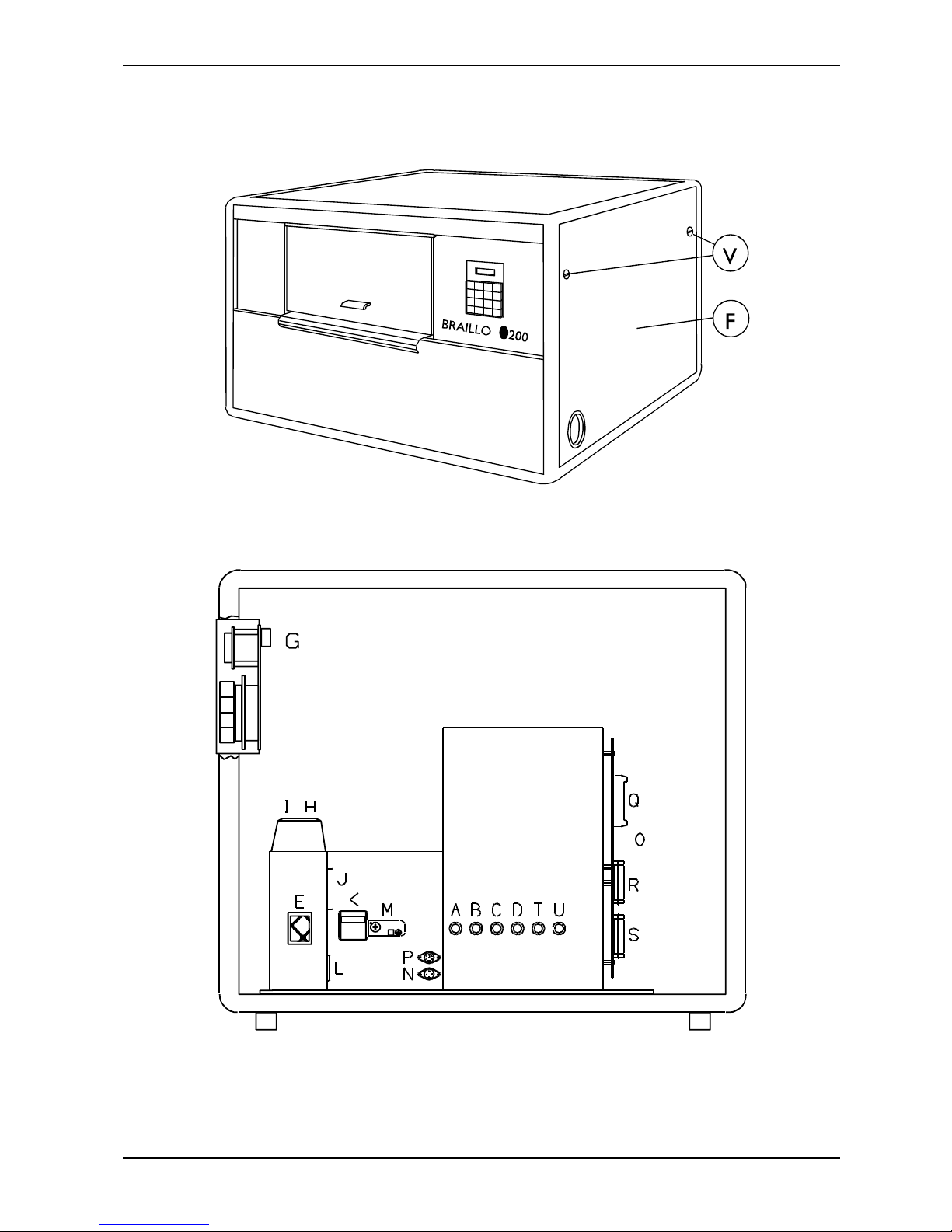
The side-panel (F) is removed by turning the two screws (V) 1/4 of a revolution - use a coin or a
screwdriver. Pull out the upper edge first, and then lift the side-panel up and out. Place it aside.
Disconnect the cables for the Operating Panel (G) and the Fan (H).
The cover can now be carefully removed by lifting the end with the fans slightly up and over on to the
baseboard. This small forward movement will free the side-panel end of the cover making it possible for
it to be tilted upwards.
The Printer can now be moved to the desired location. Afterwards, replace the cover (in reverse order of
above) and reconnect (G) and (H).
Plug the power cable in connection (L) and the data communication cable in the connection (R) or (S).
The side-panel (F) is mounted by placing the lower edge in first, and then pushing it against the cover.
Make sure that the slot on each screw's head is vertical and that the screws are aligned with the holes, then
just push the screws in until a "click" is heard. Now the side-panel is secured.
Page 7
BRAILLO M NORWAY AS B 200
3
Removal of Cover, Figures
Page 8

BRAILLO M NORWAY AS B 200
4
Note! If text of less than two pages, or text with an odd number of pages, is received without being
followed by FF on the last page, the Printer will wait for more text or FF. This is due to the doublesided operation of the printer. It waits for a signal that its buffer contains a full two page print job
before it begins printing.
1.4 Interfacing to Computer
Data can be transmitted from the computer to the Printer in two ways, either via the serial or the parallel
port. Serial transmission goes through an RS 232 C interface. Parallel transmission uses a Centronics
compatible interface.
Both connectors are of the 25 pin D-sub types, and are electrically isolated from the computer.
Serial communication:
Connect the enclosed cable, ensure that the computer and the Printer have exactly the same transmission
settings. If not, they can be changed either on the computer or the Printer. Braillo Norway recommends
a baud rate of 9600 Baud for quick and reliable communication.
When the Printer is delivered from Braillo Norway, the serial port has the following transmission settings:
Baud rate: 9600
Parity: NO
Data bit: 8
Stop bit: 1
To change these settings on the Printer, see chapter 2.1 "Operating Panel". To make changes on your
computer, consult the user manual.
If changes in the transmission settings are to be done on the computer, we recommend that these changes
are added in the start-up file, AUTOEXEC.BAT, so that they occur automatically with each startup. The
command for this might be: MODE COM1:96,N,8,1,P.
Parallel communication:
Connect the enclosed cable, ensure that the Printer is set for parallel communication, and start printing.
The Printer recognizes the following control codes:
CR: New line (fills the rest of the line with space).
LF: New line (fills the rest of the line with space).
If both CR and LF, in any order, immediately follow each other, only one new line command is executed
by the Printer.
FF: New page (fills the rest of the page with space).
(After 2 x FF the paper is fed one sheet forward, filling the rest of the page plus the next page with blank
space).
If the lines are not terminated with CR or LF, the text which follows will be printed on the same line, until
the line length set in the Printer is filled. Remaining characters will be wrapped to the next line. The same
situation will occur if FF is missing in the text, the text which follows will appear on the same page,
because there is no internal text formatting.
The Printer can also be controlled by ESC-sequences to change its settings and modes. Please see chapter
2.7 "Escape-sequences".
Page 9
BRAILLO M NORWAY AS B 200
5
Note! When using more than one FF command, make sure to have a space between them to keep them
separated. E.g. FF FF FF.
To have one sheet (two pages) printed, one of the following sequences must be executed:
Double-sided printing:
A) Two pages full of text.
B) More than one page of text and one FF.
C) Less than one page of text and two FF.
D) Two FF-commands.
E) Less than one/two pages and depress Dump Buffer.
Single-sided printing:
A) One page full of text.
B) Less than one page of text and one FF.
C) Less than one page of text and depress Dump Buffer.
Connecting the Printer to the Mains and Computer.
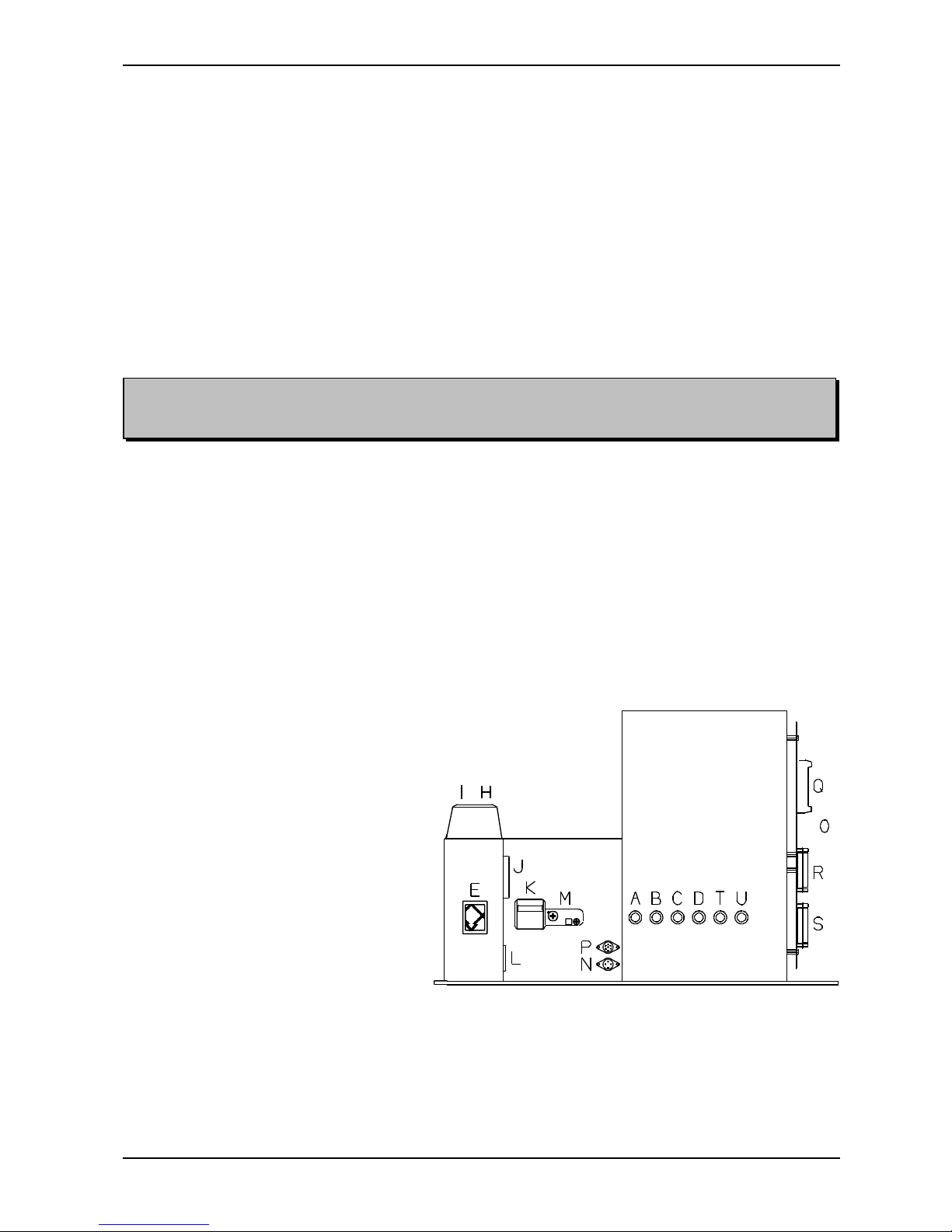
See the figure below.
Connect the enclosed mains power cable to the inlet (L). If the plug on the mains power cable is to be
replaced, observe that the yellow/green wire is the ground (earth) wire.
With parallel communication, use connector (R). With serial communication, use connector (S).
A: Fuse, magnet rack A
B: Fuse, magnet rack B
C: Fuse, magnet rack C
D: Fuse, magnet rack D
E: Main switch
H: Outlet, fan
I: Outlet, motor
J: Hour counter
K: Main fuse
L: Power inlet
M: Reset switch, motor fuse
N: Connector, ext. alarm
O: Motherboard
P: Connector, Braillo Cut
Q: Connector, operating panel
R: Parallel port
S: Serial port
T: Fuse, stepping motor
U: Fuse, relays
Page 10

BRAILLO M NORWAY AS B 200
6
Page 11

BRAILLO M NORWAY AS B 200
7
2. OPERATING
2.1 Operating Panel
There is an audio alarm which sounds if a problem has occurred, and the display will show what has
happened.
There are three sheet counters. The one at the right-hand side of the display shows the total number of
printed sheets and cannot be reset.
The remaining two counters - Count1 and Count2, are displayed one-at-a-time on the left-hand side of
the display and can be reset.
Page 12

BRAILLO M NORWAY AS B 200
8
Description of Functions of Operating Panel
COUNT1 / COUNT2
Selects between sheet counter (not pages!) 1 and 2. When this button is in the outer (released) position,
counter 1 is displayed on the left-hand side of the display, and when the button is in (depressed), counter
2 is displayed.
DUMP BUFFER
During normal double sided printing, a volume of text of less than two pages will not be printed. This is
because the Printer is waiting for a full two page print job. By pushing DUMP BUFFER, the text
remaining in the buffer will be printed. See chapter 1.4, "Interfacing to Computer".
PRINT VALUES
Prints the current values of the LAYOUT, I/O and ASCII-TABLES.
See chapter 2.3, "Print Values".
SCROLL
Scrolls through the menus activated by:
I/O, ASCII-TABLES, LAYOUT 1, LAYOUT 2, LAYOUT 3 or LAYOUT 4 buttons.
RESET COUNT
Resets the sheet counter selected by COUNT1/COUNT2.
TEST PRINT
This button has two functions: Test Print and Ready/Continue.
Test Print:
1st push down:
Prints a X-pattern on both sides of the sheet which shows each pin from each magnet rack printing
on a separate line. Useful when searching for missing dots.
2nd push down:
Prints full cells and empty lines, together with the ASCII-table on both sides of the sheet. Useful
for testing the printing pressure adjustments, and to see how the paper tolerates tightly grouped
dots.
3rd push down:
Prints full cells and empty lines, together with the ASCII-table single-sided. Useful for testing the
printing pressure adjustments.
4th push down:
Prints a test pattern made of dot 1,3,5 and 2,4,6, single-sided. Useful when searching for extra
dots.
5th push down:
As 1st push down etc.
Ready/Continue:
When the Printer runs out of paper, the message PAPER OUT is shown on the display. Insert new
paper, and push TEST PRINT in and out, and the printer will continue printing the last print job.
Do not use RESET PRINTER as this will clear the print job from the Printer's memory!
Page 13

BRAILLO M NORWAY AS B 200
9
Note! This button will not change between the 6 and 8 dot print mode, it just displays which ASCIItables that will be used in these modes.
Note! Scrolling trough the resident ASCII-tables will clear any user table that has been downloaded
from the computer. If this table is to be activated again, it must be reloaded from the computer.
I/O - Input/Output
Selects between serial and parallel port, and sets the data transmission values for the serial port.
1st push down: Displays which port is active.
To select serial or parallel port, the button must be depressed and then released. Now, while the display
still shows the active port, press SCROLL to select the other port.
If the serial port is active, a 2nd push down will make it possible to use SCROLL to adjust the settings
for the serial port.
ASCII-TABLES
This button has two functions:
It selects which 6 and 8 dot ASCII-table to be active for braille conversion and it displays the 6 and 8 dot
ASCII-tables currently active.
1st push down:
Displays the active ASCII-table, number and country for the 6 dot mode.
2nd push down:
Displays the active ASCII-table, number and country for the 8 dot mode.
To select from the 8 resident ASCII-tables in the Printer, the following procedure should be used:
Push the ASCII-tables button, release it, then push it once again and hold. Now it is possible to change
the active ASCII-tables with the SCROLL button. ASCII-table pair number one will be displayed first.
(If there has been a pair of ASCII-tables loaded from the computer, these will be displayed first). If
SCROLL is released, and pressed again, ASCII-table pair no. two will be displayed. This continues until
pair no. eight is reached, whereafter it will start at pair number one again.
LAYOUT 1
Selects sheet length, line length or Single/Double -sided printing.
Use SCROLL to choose each setting.
LAYOUT 2
Selects normal or Z-fold printing, if page 1 is to be up or down, and to choose between 6 and 8 dot braille.
Use SCROLL to choose new settings.
LAYOUT 3
Selects the line spacing.
The line spacing is adjustable in steps from 0 to 16. In millimetres this will be from 0 to 5.08 mm. (One
step equals 0.3175 mm). The setting 16 is the standard line spacing, 5.08 mm (0.2"). 8 is the setting for
graphic, 2.54 mm (0.1"), and so on.
The function “Single or Double line spacing” will double the given line spacing. If, e.g. the current line
spacing is 13 steps (4.1275 mm), selecting Double line spacing will increase it to 26 steps (8.255 mm).
Use SCROLL to choose new settings.
Page 14

BRAILLO M NORWAY AS B 200
10
Note! Please keep in mind that there is a difference in the terms “page length” and “sheet length”. By
page length we mean the number of lines of text to be printed on a page, and by sheet length we mean
the physical size of a sheet of paper in inches.
The number of lines which can be printed on a page, is dependent on whether 6 or 8 dot braille is used,
the selected line spacing, and the page length settings.
LAYOUT 4
Selects Page Adjust and Page Margin.
The “Page Adjust” can have one of the following values:
NoFFed: No form feed. This setting will cause the printer to print continuously. There are no
pagebreaks, and it is possible to print an “infinity long sheet”.
Max: Maximum. This is the standard setting, and will give a maximum number of lines per page.
How many lines that will fit on a page will depend on, e.g. the sheet length, if it’s 6 or 8
dot braille, the line spacing, and margins.
Max-1 to -9: Maximum, -1 to -9. This setting will decrease the number of lines on each page with 1 to
9, (depending on the selected number). If, e.g. the maximum number of lines would be 29,
and the setting “Max-4" is selected, the resulting number of lines will be 25.
This function will centre the text vertically on the page, to keep the top and bottom margin
approx. equal.
The “Page Margin” function will adjust the page margin in steps from 0 to 20. The standard setting is 8,
(8 = normal). The page margin will give different effect when used on single-sided, compared with doublesided. On double-sided printing, one step is equal to 0.6350 mm, and the text will be centred vertically on
the page. If, e.g. a page margin on 6 steps is selected, the printer will print closer to the edges of the paper,
and if a page margin on 20 steps is selected, it will give a larger page margin. This will affect both top and
bottom margins, i.e. page margin.
On single-sided printing, however, the page margin will actually work as a top margin. (Note! The page
lay out must be set to normal to be able to do the following). One step is equal to 0.6350 mm. It will
“push” the text downwards the sheet. When the text reaches the bottom, (meaning that there will not be
enough space on this page for the last line), this line will wrap over to the next page.
Use SCROLL to choose new settings.
FINE ADJUST
Positions the paper.
Each push down moves the paper a distance equal to 0.5".
FORM FEED
Advances the paper to the next sheet.
Page 15

BRAILLO M NORWAY AS B 200
11
Note! The Current Values are saved in the battery-backup memory, and they will remain even if the
power is turned off.
RESET PRINTER
Resets the CPU unit and clears the buffer.
Must always be used if an error occurs (Printer Error in the display).
RESET ALARM
For alarms, the audio alarm can be reset (e.g. Printer Alarm, Out of Paper).
For errors (Printer Error in the display), however, the RESET PRINTER must be used.
Using the Menu Buttons
With help of the menu buttons (LAYOUT 1, LAYOUT 2, LAYOUT 3 and LAYOUT 4) the current
values can be changed.
The first push of a menu button shows which setting is currently active - its current value.
If these settings are correct, wait a few seconds for the timeout to expire, or press the RESET PRINTER
button and the setting will remain.
If you would like to change one of the settings, push the button several times, until the desired function
is shown on the display, then hold it down. By using SCROLL, the complete menu for the function can
be reviewed in the display. When the correct value is shown, release the button and either wait for the
timeout, or use RESET PRINTER.
The I/O and ASCII-table buttons differ slightly from this routine. Please see their button descriptions
previously in this chapter.
Page 16

BRAILLO M NORWAY AS B 200
12
2.2 Current Values and Options
Page 17

BRAILLO M NORWAY AS B 200
13
2.3 Print Values
This function gives a printout of the settings which are currently active in the Printer; It also gives
information about the 8 ASCII-tables in the Printer.
When Print Values is used, the Line Length setting must be at least 36 characters. If not, this message will
appear in the display:
NB! Line Length
Minimum 36 Char.
To be able to print the current values, change the line length to min. 36 characters.
Print Values might look like this:
BRAILLO NORWAY
VERSION 000.19 D
CURRENT VALUES
COMMUNICATION = SERIAL
BAUD RATE = 9600
PARITY = NO
DATA BIT = 8
STOP BIT = 1
SHEET LENGTH = 12
LINE LENGTH = 42
PRINT = DOUBLE
LAYOUT = NORMAL
PAGE 1 = UP
DOT = 6
LINE SPACING = NORMAL
LINE SING/DOUB = SINGLE
PAGE ADJUST = MAX
PAGE MARGIN = NORMAL
SHEET COUNTER 1= 87654321
ASCII TABLE
NO 2 = ENGLAND 6 DOT 044.00
ENGLAND 8 DOT 044.00
"Sheet counter" shows the number of printed sheets (Not pages!). This is the same counter as on the righthand side of the display. "ASCII table" shows which ASCII-table is active.
Page 18

BRAILLO M NORWAY AS B 200
14
The remaining information in the Print Values printout tells which ASCII-tables are available in the
EPROM, and might look like the list below.
BRAILLO NORWAY
ASCII TABLES IN PROM
NO 1 = DENMARK 6 DOT 045.00
DENMARK 8 DOT 045.00
NO 2 = ENGLAND 6 DOT 044.00
ENGLAND 8 DOT 044.00
NO 3 = GERMANY 6 DOT 049.03
GERMANY 8 DOT 049.03
NO 4 = GERMANY 6 DOT 049.04
GERMANY 8 DOT 049.04
NO 5 = ICELAND 6 DOT 354.00
ICELAND 8 DOT 354.00
NO 6 = ITALY 6 DOT 036.02
ITALY 8 DOT 036.02
NO 7 = NORWAY 6 DOT 047.03
NORWAY 8 DOT 047.03
NO 8 = SWEDEN 6 DOT 046.01
SWEDEN 8 DOT 046.01
All the 8 tables are resident in the Printer. The table which is active is shown under the "ASCII table"
section of the printout. To select another table (among the 8), refer to chapter 2.1, "Operating Panel".
Note: This is just an example. The ASCII-tables listed will be dependent upon the combinations which are
included in the printer. Some common combinations are listed below:
EURO 1 931203 EURO 2 931203 EURO 3 930106
1 045.00 Denmark 1 032.00 Belgium 1 043.00 Austria
2 044.00 England 2 044.00 England 2 042.00 Czech/Slovakia
3 049.03 Germany 3 033.00 France 3 044.00 England
4 049.04 Germany 4 049.03 Germany 4 049.03 Germany
5 354.00 Island 5 049.04 Germany 5 049.04 Germany
6 039.02 Italy 6 039.02 Italy 6 030.00 Greece
7 047.03 Norway 7 047.03 Norway 7 036.00 Hungary
8 046.01 Sweden 8 041.00 Switzerland 8 047.03 Norway
AMERICA 931203 ASIA1 930118 ASIA2 941025
1 055.00 Brazil 1 033.01 France 1 033.01 France
2 033.01 France 2 049.04 Germany 2 049.04 Germany
3 049.04 Germany 3 081.00 Japan 3 098.00 Iran
4 039.02 Italy 4 965.01 Kuwait 4 965.01 Kuwait
5 047.03 Norway 5 060.01 Malaysia 5 060.01 Malaysia
6 351.10 Portugal 6 047.03 Norway 6 047.03 Norway
7 034.00 Spain 7 966.00 Saudi Arabia 7 966.00 Saudi Arabia
8 001.00 USA 8 001.00 USA 8 001.00 USA
Page 19

BRAILLO M NORWAY AS B 200
15
Printer
BUFFER empty
NB! Line Length
Minimum 36 Char.
Printer
Out of Paper
2.4 Messages/Error Messages
The text in the display can be divided into three groups; Messages, Alarms and Error Messages. With
Messages, the Printer operates normally. With some Alarms, the Printer can be operated to a certain
degree, while other Alarms are like Error Messages, in that the Printer cannot be operated, and RESET
PRINTER must be used.
The audio alarm (BEEP) is sounded for both alarms and error messages.
Messages:
1 When DUMP BUFFER is used, and the input buffer is
empty, the message "BUFFER empty" is shown on the
display. The Printer is then ready to begin a new print
job. Note: If there is text remaining in the buffer and
"Dump Buffer" is not used, the text will appear at the
beginning of the next print job.
2 When PRINT VALUES is used, and the line length is set
to less than 36 characters, this message will appear on
the display. To print the current values, first set the line
length to 36 characters or more.
Alarms
1 When the Printer runs out of paper, the audio alarm is
sounded, and the Printer stops at the end of the next
page.To continue printing, press RESET ALARM and
then TEST PRINT after the paper has been replaced. For
information, see TEST PRINT - Ready/Continue, in
chapter 2.1 "Operating Panel".
If the alarm is sounded when there still is paper in the machine, this may have been caused by
one of the following:
A. Paper dust in the paper out sensor.
B. The paper guide which the paper out sensor is attached to might be bent or damaged,
so the distance from the sensor to the paper is too big to detect the paper.
C. The sensor is not connected.
If one of these problems occurs, clean the sensor, make sure that it’s connected to the
motherboard, and check that the sensor is not more that 2 mm from the paper surface.
Page 20

BRAILLO M NORWAY AS B 200
16
Printer
Buffer Overflow
Printer Alarm
Overrun/Framing
Printer Alarm
Parity
Printer Alarm
ESC-Sequences
The following alarms are usually caused by a problem with the handshake in the data communication
between the computer and the Printer, and it will be necessary to press RESET printer.
The text which remains in the buffer during these alarms can be printed by using DUMP BUFFER.
However, during these alarms one must check the transmission parameters for both the Printer and the
computer, and also possibly the software in use. If any changes are made on the Printer, one will have
to RESET PRINTER to register these changes.
4 This alarm indicates that the computer has not registered
that the input buffer in the Printer is full, and continues to
send data which causes the buffer to overflow.
The text which remains in the buffer can be printed by
using DUMP BUFFER.
If this alarm occurs, check the transmission parameters
for both the Printer and the computer, and also possibly
the software in use.
5 Error in at least one of the following transmission
parameters: Baud rate, no. of data bits and / or no. of
stop bits. If this alarm occurs, check the transmission
parameters for both the Printer and the computer, and
also possibly the software in use.
6 Error in the parity check in serial communication. If this
alarm occurs, check the transmission parameters for both
the Printer and the computer, and also possibly the
software in use.
7 Some irregularities have been detected when receiving
escape-sequences. If this alarm occurs, check the
transmission parameters for both the Printer and the
computer, and also possibly the software in use. If the
escape-sequences are sent by a batch-file or are
integrated in the text-file, be sure that the correct ASCIIvalue combinations are used.
Page 21

BRAILLO M NORWAY AS B 200
17
Printer Error
General Failure
Printer Error
Start Motor
Printer Error
Stop Motor
Printer Error
Paper Feed
On error messages, the Printer cannot be operated, and RESET PRINTER must be used.
1 The reason might be:
A. If the main motor starts, but for some reason
stops because of, for example, a blown (released)
motor fuse, this message appears in the display,
together with the audio alarm. Reset the motor
fuse.
B. The belt on the Printer breaks during printing.
Check the belt, and replace if needed.
2 If the main motor does not start, this error message is
shown in the display. The reason might be:
A. The motor is not connected.
Check that the cable to the motor is connected.
B. The motor fuse may have been released.
Reset motor fuse. See figure in chapter 5.2,
"Electric Unit".
C. System error.
3 The main motor does not stop. The reason might be:
A. The motor relay contacts have burned.
The relay must be exchanged by service
personnel.
B. System error.
4 Disagreement between the paper feed assembly (the
paper) and the program system.
The reason might be:
A. The paper is stuck, and the paper feed motor has
slipped. Free the paper jam, push RESET
PRINTER.
B. System error.
Page 22
BRAILLO M NORWAY AS B 200
18
Note! If the Printer has run out of paper, perform step 2 and 3, without resetting the Printer. Press the
TEST PRINT button in and out to restart the printing, and the Printer will continue from the place
where it ran out of paper without losing any text.
2.5 Inserting Paper
Paper should be inserted into the Printer in the following manner:
1. Turn on the main switch, if the printer is not already switched on. (Red power lamp lights
up.)
2. Place a box of paper at the back of the Printer. (Opposite from the operating panel.)
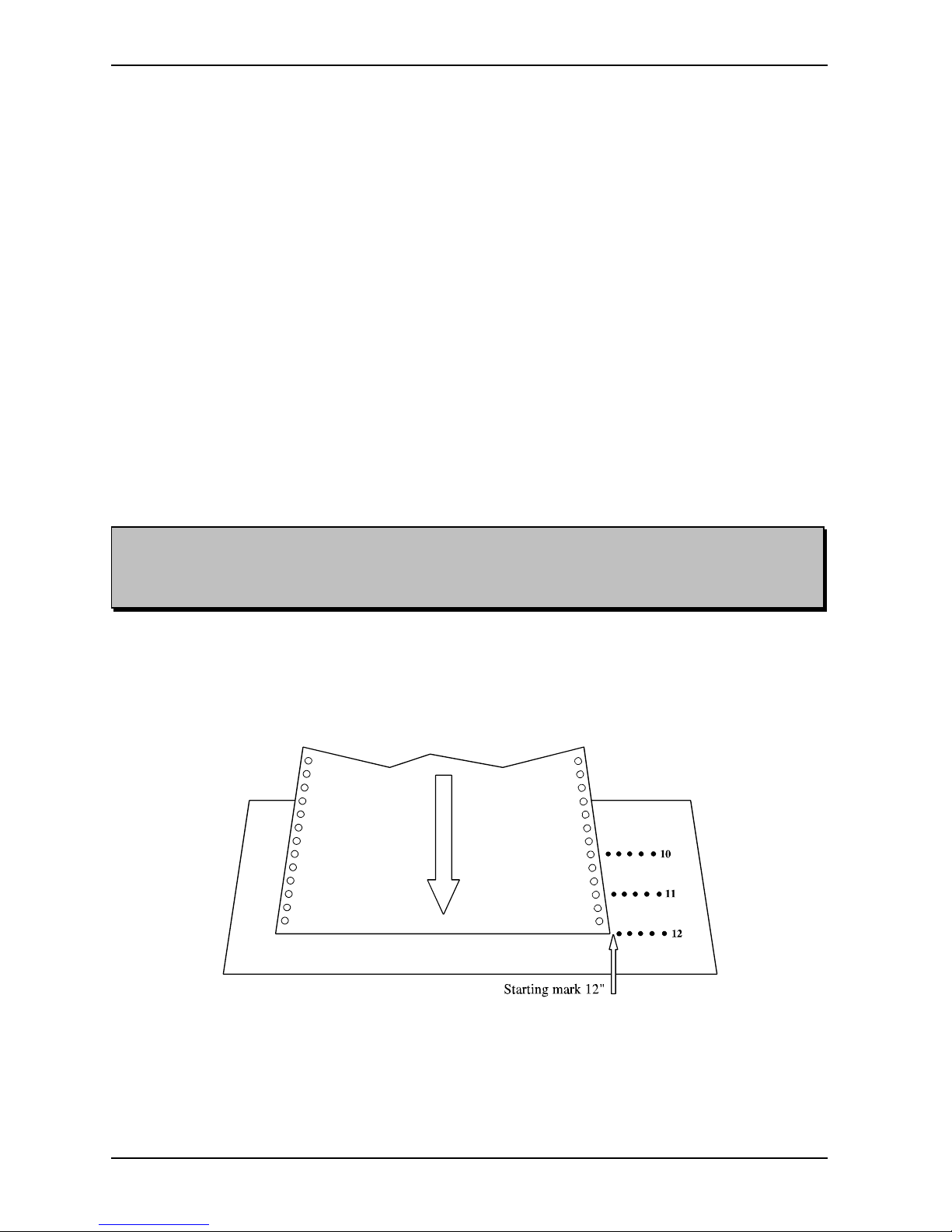
3. Insert the paper between the two knobs, and then through the slit in the paper guide. Insert
about the length of one sheet. Go to the front of the Printer. Lock the paper into the
tractor-feed. By using the FINE ADJUST button, adjust the paper with respect to the
starting mark (notch) corresponding to the chosen sheet length. (See figure below.)
4. Push RESET PRINTER.
5. Push RESET COUNTER, if desired.
6. The Printer is now ready to start printing.
Page 23

BRAILLO M NORWAY AS B 200
19
Note! To get the single-sided test print to alternate sides, LAYOUT 2 must be used to set the layout
to Z-fold.
2.6 Test Print
This Braillo Printer has both single-sided and double-sided (interpoint) test print patterns. See also TEST
PRINT in chapter 2.1 "Operating Panel".
The test print consists of a X-pattern, some full cell lines, empty cell lines, the complete ASCII-table and
a pattern consisting of a character with dot 1,3,5 combined with a character with dot 2,4,6.
The test print program is designed to ensure that the 168 printing mechanisms functions properly.
It is recommended to print a few pages of test print before beginning the day's production.
How to use the Test Print:
1st push down: Prints an X-pattern on both sides of the sheet which shows each pin from each
magnet rack printing on a separate line. Useful when searching for missing dots.
2nd push down: Prints full cells and empty lines, together with the ASCII-table on both sides of the
sheet. Useful for testing the printing pressure adjustments, and to see how the
paper can take heavy printing.
3rd push down: Prints full cells and empty lines, together with the ASCII-table single-sided. Useful
for testing the printing pressure adjustments.
4th push down: Prints a test pattern made of dot 1,3,5 and 2,4,6, single-sided. Useful when
searching for extra dots.
5th push down: As 1st push down etc.
The chapter 3.2 "Principal Design of Printing Procedure" illustrates how the printing mechanisms are
placed. This illustration combined with the printing page sequences, chapter 3.3 "Table of Page
Sequences", makes it possible to locate the faulty printing mechanism.
Instruction for troubleshooting will be illustrated by examples in chapter 3.1 "Troubleshooting".
Page 24

BRAILLO M NORWAY AS B 200
20
Note! When the Printer receives an escape-sequence, it will have first priority. This means that,
regardless of the setting made before and regardless what the operator panel dictates, the most recent
escape-sequence will take precedence.
Note! Escape-sequences should be placed at the very beginning of the first page on the sheet, (e.g page
1, 3, 5, 7 ...). However, a software form feed can be placed wherever needed. (If there is a command
on the other pages, it will be skipped).
All page formatting which is done on the front page will also format the back of the same sheet. It is
e.g. not possible to have 8 dot braille on the front page and 6 dot on the back page. It is possible to
mix 6 and 8 dot braille however, as long as it is done on two different sheets.
2.7 Escape-Sequences
What is an escape-sequence?
An escape-sequence is just a name for a code which is sent from the computer to the Printer to change
the parameters which control the way the Printer works. All parameters that can be set via the operator
panel, can also be changed with the help of escape-sequences, (except those for the data communication,
i.e. active port, Baud rate, Data bit, Stop bit, and Parity).
This makes it possible to have different codes (read; escape-sequences) stored in a document. For
example, when the document is sent to the Printer, these codes are sent automatically first (so that the
Printer sets itself in the correct mode and format automatically).
When the Printer receives ASCII 27, it knows that this code and one or more of the following codes are
not text, but commands. This makes the Printer stop writing characters, and begins performing the
commands.
How to make escape-sequences?
How to make an escape-sequence depends on the computer and the software being used. To make an
escape-sequence the ASCII value 27 (hexadecimal 1B) is needed. This is the escape command.
Under MS.DOS 5.0 (or newer) this can be done in the DOS-text editor "Edit". At the DOS prompt, type
"edit", press Enter, and the editor appears. Now, to create the ASCII value for escape press Ctrl-P, and
then press the ESC-key. A left arrow will appear on the monitor. This indicate the escape character ASCII
27.
E.g. to make an escape-sequence to set the Printer to 6 dot mode, the command is ESC J0, and in "Edit",
it is done as follows; Press Ctrl-P, then press the ESC-key to create the left arrow. Then type J0, and the
command is completed. Save the file, exit the editor, and copy this file to the Printer. This will set the
Printer to 6 dot mode.
The same thing can be done in Word Perfect 5.1: Press Ctrl-V, then press the ESC-key. The characters
will appear on the monitor indicating the escape character ASCII 27. To achieve the same command as
in the previous example, press J0. Now this must be saved as a DOS-text file. This is done by pressing
Ctrl-F5, then 1 for DOS-text and 1 for Save. Give the file a name, exit WP, and copy the file to the
Printer. This will set the Printer to 6 dot mode.
In order to use some of these commands correctly, the ASCII values must sometimes be combined. (For
example the number of characters per line and the length of the sheet).
Page 25

BRAILLO M NORWAY AS B 200
21
Note! The escape-sequences will be executed immediately if the printer is not running. However, if the
printer is running, the escape-sequences will keep their place in the document, and will be executed
when this particular page is printed.
Also keep in mind that any page formatting command must be kept on the front page of a sheet. Then
the command will affect both the front and back page, i.e. one sheet.
If there are page formatting commands on the back page of a sheet, these comands will be skipped.
Overview of the escape-sequences:
ESC A nn - Sheet length. nn can be from 08 to 28 (4 to14 inch).
ESC B nn - Line length. nn can be from 10 to 42 characters.
ESC C n - Print Format. n can be 0 or 1, single-sided (0) or interpoint (1).
ESC H n - Page Layout. n can be 0 or 1, Normal (0) or Z-fold printing (1).
ESC I n - Page 1 up/down. n can be 0 or 1, up (0) or down (1).
ESC J n - 6 / 8 dot braille. n can be 0 or 1, 6 (0) or 8 (1) dot braille.
ESC M nn - Line Spacing. nn can be from 0 to 16 step.
ESC N n - Line Single/Double. n can be 0 or 1, single (0) or double line spacing (1).
ESC R n - Page adjust. n can be from 0 to 9 lines.
ESC S n - Form Feed Mode. n can be 0 or 1, no form feed (0) or normal form feed (1).
ESC T nn - Page margin. nn can be from 0 to 20 step.
ESC 0 - Soft Reset
ESC 1 - Soft Form Feed
ESC 3 - ASCII-Table from PC
Please see the following explanations on how to combine different values to get the different escapesequences.
Page 26
BRAILLO M NORWAY AS B 200
22
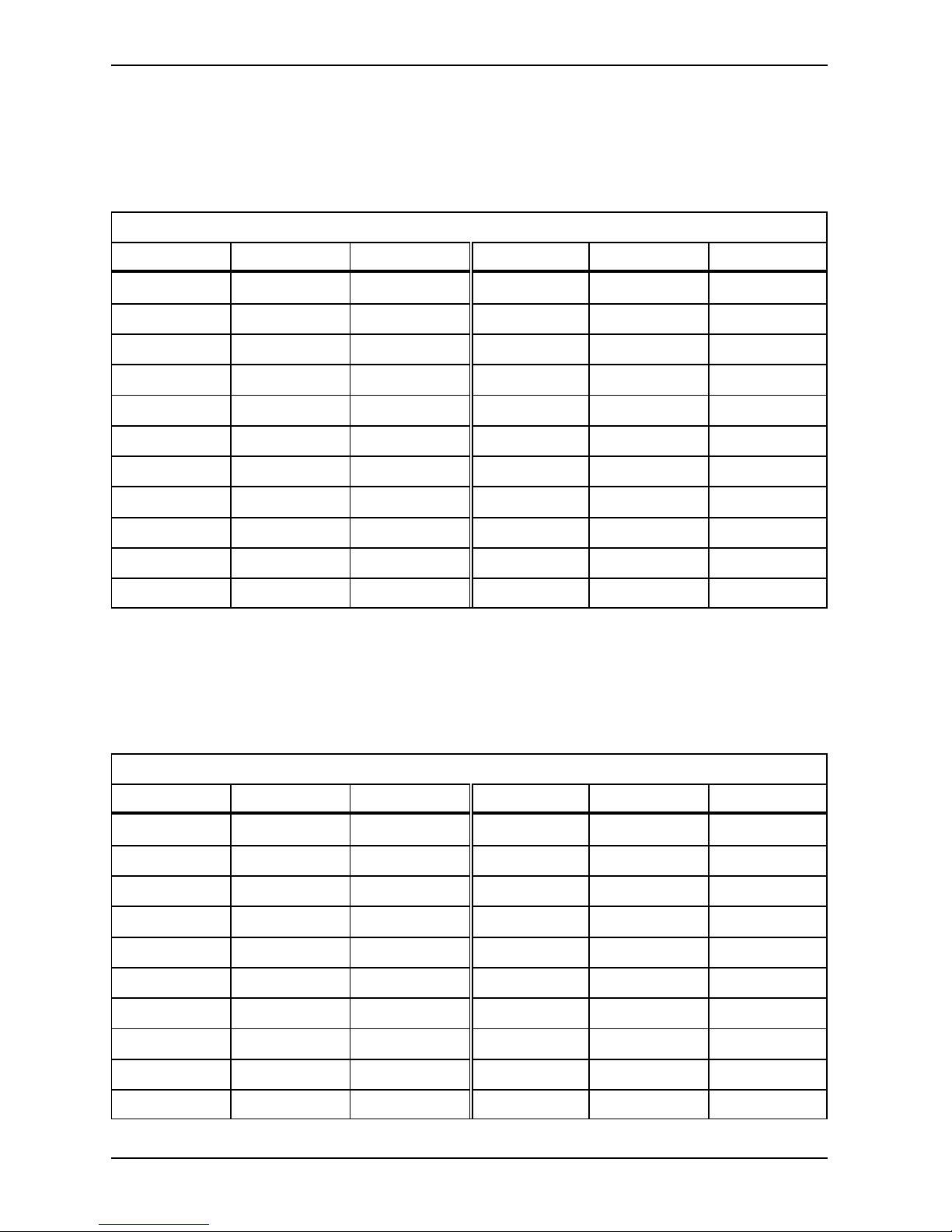
Sheet length:
ESC A nn - Sheet length. nn can be from 4 to14 inches.
nn can be a number from 8 to 28, corresponding to the length of the sheet in inches times two. (A 12 inch
sheet will have the number 24).
Sheet Length
Inches ASCII HEX Inches ASCII HEX
04.0 027 065 048 056 1B 41 30 38 09.5 027 065 049 057 1B 41 31 39
04.5 027 065 048 057 1B 41 30 39 10.0 027 065 050 048 1B 41 32 30
05.0 027 065 049 048 1B 41 31 30 10.5 027 065 050 049 1B 41 32 31
05.5 027 065 049 049 1B 41 31 31 11.0 027 065 050 050 1B 41 32 32
06.0 027 065 049 050 1B 41 31 32 11.5 027 065 050 051 1B 41 32 33
06.5 027 065 049 051 1B 41 31 33 12.0 027 065 050 052 1B 41 32 34
07.0 027 065 049 052 1B 41 31 34 12.5 027 065 050 053 1B 41 32 35
07.5 027 065 049 053 1B 41 31 35 13.0 027 065 050 054 1B 41 32 36
08.0 027 065 049 054 1B 41 31 36 13.5 027 065 050 055 1B 41 32 37
08.5 027 065 049 055 1B 41 31 37 14.0 027 065 050 056 1B 41 32 38
09.0 027 065 049 056 1B 41 31 38
Default is 12 inches.
Setting the line length:
ESC B nn - Line length. nn can be from 10 to 42 characters.
Line Length
Char ASCII HEX Char ASCII HEX
10 027 066 049 048 1B 42 31 30 20 027 066 050 048 1B 42 32 30
11 027 066 049 049 1B 42 31 31 21 027 066 050 049 1B 42 32 31
12 027 066 049 050 1B 42 31 32 22 027 066 050 050 1B 42 32 32
13 027 066 049 051 1B 42 31 33 23 027 066 050 051 1B 42 32 33
14 027 066 049 052 1B 42 31 34 24 027 066 050 052 1B 42 32 34
15 027 066 049 053 1B 42 31 35 25 027 066 050 053 1B 42 32 35
16 027 066 049 054 1B 42 31 36 26 027 066 050 054 1B 42 32 36
17 027 066 049 055 1B 42 31 37 27 027 066 050 055 1B 42 32 37
18 027 066 049 056 1B 42 31 38 28 027 066 050 056 1B 42 32 38
19 027 066 049 057 1B 42 31 39 29 027 066 050 057 1B 42 32 39
Page 27
BRAILLO M NORWAY AS B 200
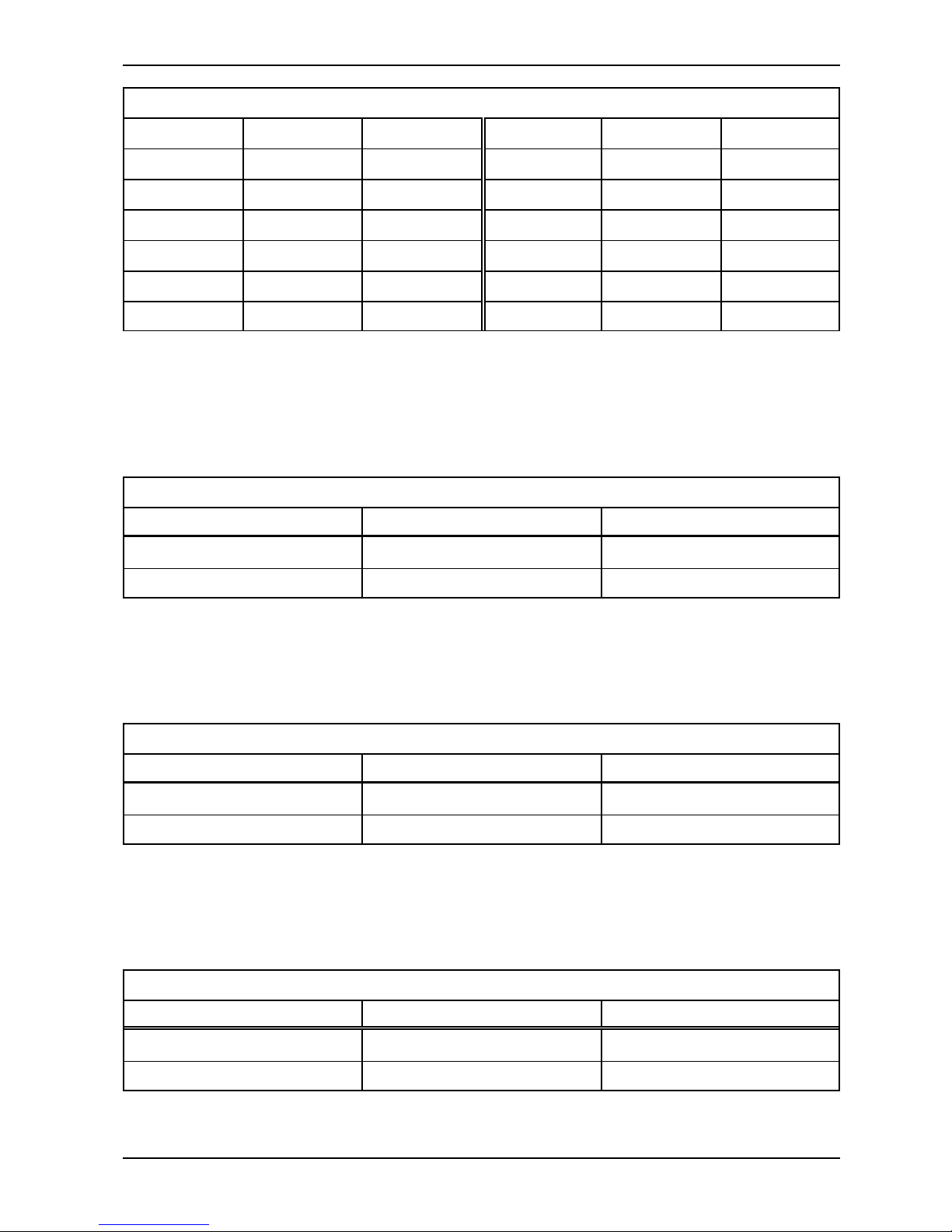
Line Length
23
30 027 066 051 048 1B 42 33 30 37 027 066 051 055 1B 42 33 37
31 027 066 051 049 1B 42 33 31 38 027 066 051 056 1B 42 33 38
32 027 066 051 050 1B 42 33 32 39 027 066 051 057 1B 42 33 39
33 027 066 051 051 1B 42 33 33 40 027 066 052 048 1B 42 34 30
34 027 066 051 052 1B 42 33 34 41 027 066 052 049 1B 42 34 31
35 027 066 051 053 1B 42 33 35 42 027 066 052 050 1B 42 34 32
36 027 066 051 054 1B 42 33 36
Default is 42 characters pr. line.
Print Format:
ESC C n - Print Format. n can be 0 or 1, single-sided (0) or interpoint (1).
Print Format
Print Format ASCII HEX
Single-sided 027 067 048 1B 43 30
Double-sided 027 067 049 1B 43 31
Default is Double-sided.
Page layout:
ESC H n - Page Layout. n can be 0 or 1, Normal (0) or Z-fold printing (1).
Page Layout
Page Layout ASCII HEX
Normal 027 072 048 1B 48 30
Z-fold 027 072 049 1B 48 31
Default is Normal Page Layout.
Page 1 up or down:
ESC I n - Page 1 up/down. n can be 0 or 1, up (0) or down (1).
Page 1 Up or Down
Page 1 Up or Down ASCII HEX
Up 027 073 048 1B 49 30
Down 027 073 049 1B 49 31
Default is Page 1 Up.
Page 28
BRAILLO M NORWAY AS B 200
24
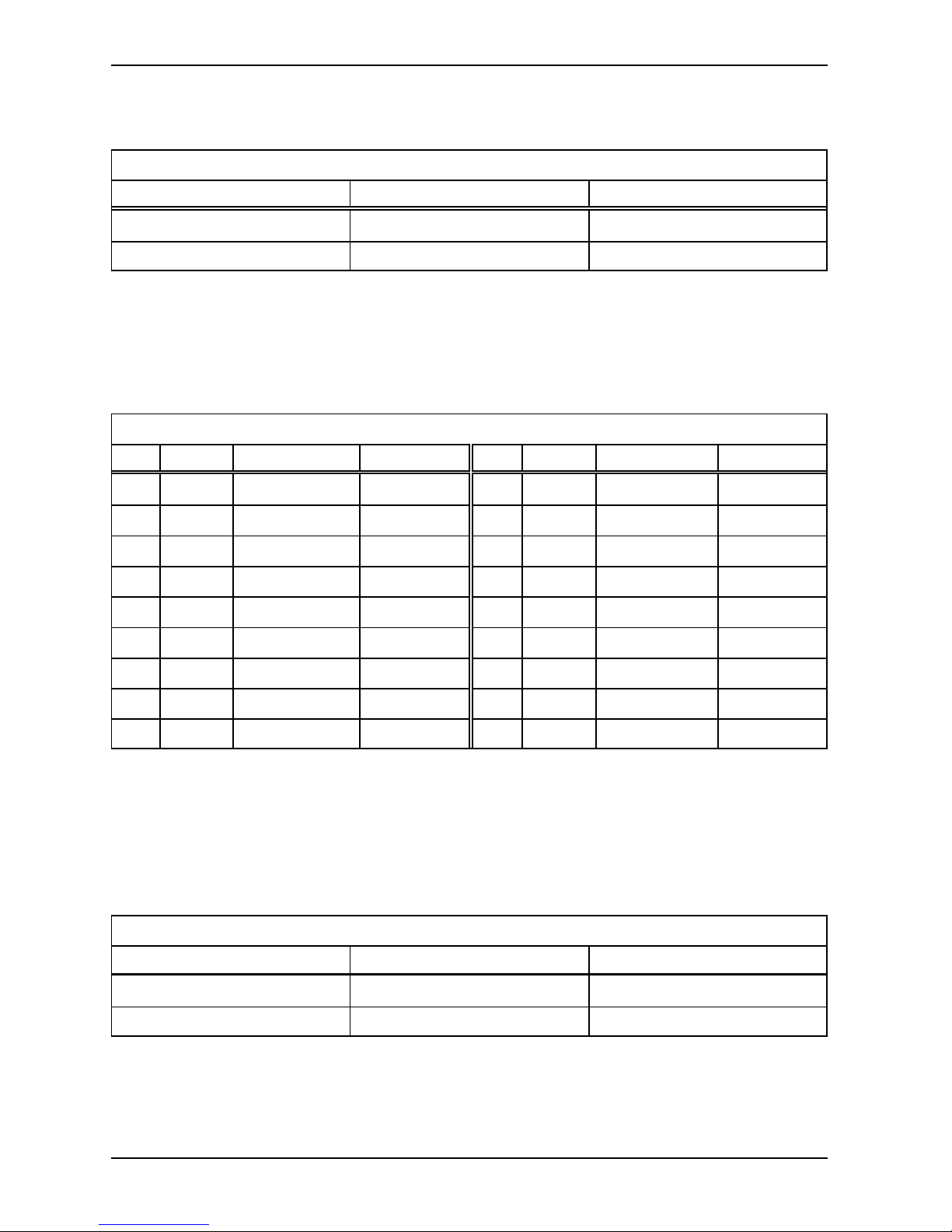
6 / 8 dot braille:
ESC J n - 6 / 8 dot braille. n can be 0 or 1, 6 (0) or 8 (1) dot braille.
6 / 8 dot braille
6 / 8 dot braille ASCII HEX
6 027 074 048 1B 4A 30
8 027 074 049 1B 4A 31
Default is 6 dot braille.
Line spacing:
ESC M nn - Line Spacing. nn can be from 0 to 16 step.
Line Spacing
Step mm ASCII HEX Step mm ASCII HEX
0 0 027 077 048 048 1B 4D 30 30 9 2.8575 027 077 048 057 1B 4D 30 39
1 0.3175 027 077 048 049 1B 4D 30 31 10 3.1750 027 077 049 048 1B 4D 31 30
2 0.6350 027 077 048 050 1B 4D 30 32 11 3.4925 027 077 049 049 1B 4D 31 31
3 0.9525 027 077 048 051 1B 4D 30 33 12 3.8100 027 077 049 050 1B 4D 31 32
4 1.2700 027 077 048 052 1B 4D 30 34 13 4.1275 027 077 049 051 1B 4D 31 33
5 1.5875 027 077 048 053 1B 4D 30 35 14 4.4450 027 077 049 052 1B 4D 31 34
6 1.9050 027 077 048 054 1B 4D 30 36 15 4.7625 027 077 049 053 1B 4D 31 35
7 2.2225 027 077 048 055 1B 4D 30 37 16 5.0800 027 077 049 054 1B 4D 31 36
8 2.5400 027 077 048 056 1B 4D 30 38
Default is 16 steps. 16 steps are the standard line spacing (5.08 mm or 0.2"), 8 is the setting for “graphic”
(2.54 mm or 0.1"). Note that if the setting is less than 7, and there is text on each line, the dots might get
damaged in the printing process.
Single / Double Line Spacing:
ESC N n - Line Single/Double. N can be 0 or 1, single (0) or double line spacing (1).
Single / Double Line Spacing
Line Spacing ASCII HEX
Single 027 078 048 1B 4E 30
Double 027 078 049 1B 4E 31
Note! The function “Single or Double line spacing” will double the given line spacing. If, e.g. the current
line spacing is 13 steps (4.1275 mm), selecting Double line spacing will increase it to 26 steps
(8.255 mm).
Default is Single Line Spacing.
Page 29
BRAILLO M NORWAY AS B 200
25
Note! Please keep in mind that there is a difference in the terms “page length” and “sheet length”. By
page length we mean the number of lines of text to be printed on a page, and by sheet length we mean
the physical size of a sheet of paper in inches.
The number of lines which can be printed on a page, is dependent on whether 6 or 8 dot braille is used,
whether what kind of line spacing is in use, and whether page length is set for Maximum, Maximum-1
or upto -9.
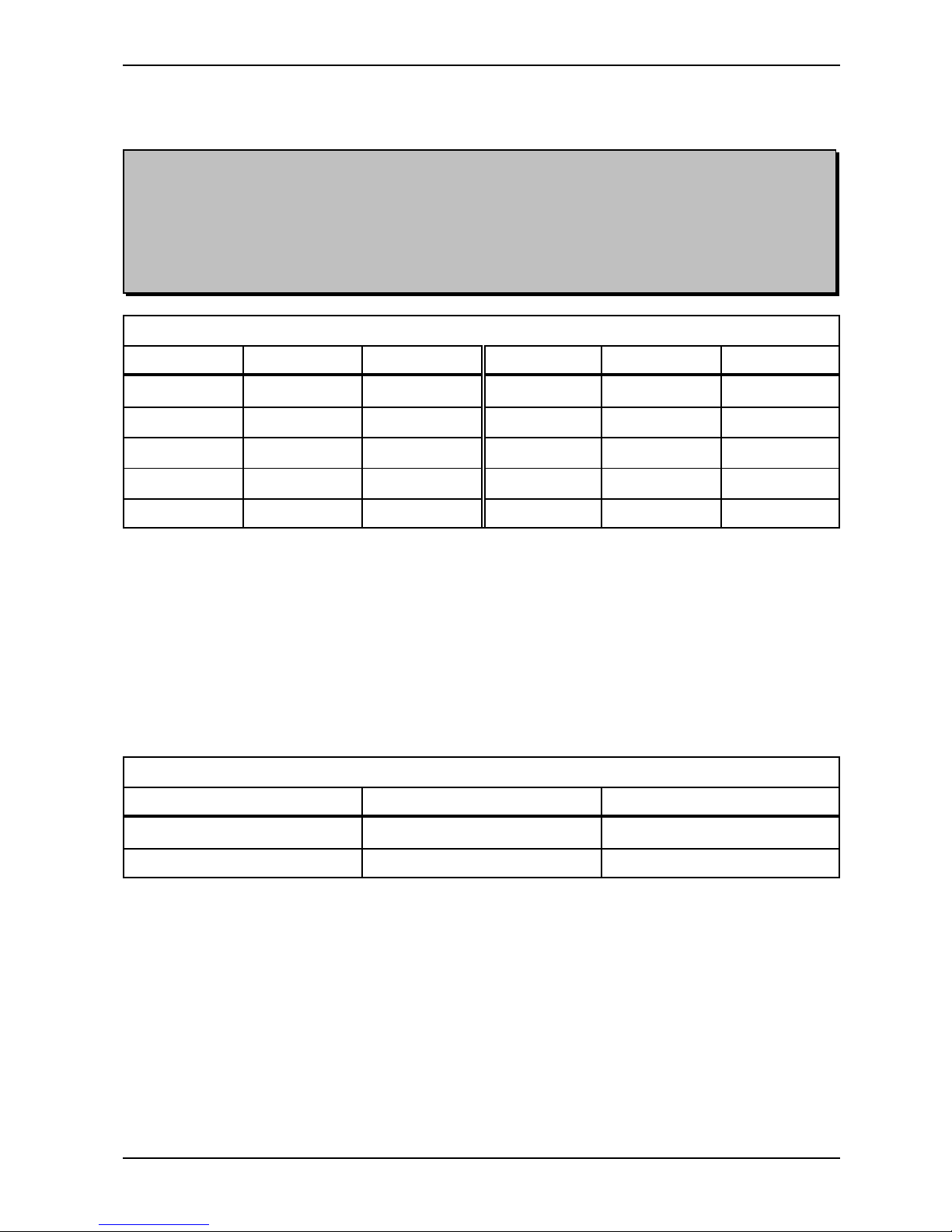
Page Adjust:
ESC R n - Page adjust. n can be from 0 to 9 lines.
Page Adjust
Omitted Lines ASCII HEX Omitted Lines ASCII HEX
0 027 082 048 1B 52 30 5 027 082 053 1B 52 35
1 027 082 049 1B 52 31 6 027 082 054 1B 52 36
2 027 082 050 1B 52 32 7 027 082 055 1B 52 37
3 027 082 051 1B 52 33 8 027 082 056 1B 52 38
4 027 082 052 1B 52 34 9 027 082 057 1B 52 39
Maximum, -1 to -9. This setting will decrease the number of lines on each page with 1 to 9, (depending
on the selected number). If, e.g. the maximum number of lines would be 29, and the setting “Max-4" is
selected, the resulting number of lines will be 25.
This function will centre the text vertically on the page and keep the top and bottom margin approx. equal.
Default is Maximum number of lines per page.
Form Feed Mode:
ESC S n - Form Feed Mode. n can be 0 or 1, no form feed (0) or normal form feed (1).
Form Feed Mode
Form Feed Mode ASCII HEX
No Form Feed 027 083 048 1B 53 30
Normal Form Feed 027 083 049 1B 53 31
Default is Normal Form Feed.
Page 30
BRAILLO M NORWAY AS B 200
26
Note! This command is used to reset the Printer. It is used from the computer and has the same effect
as pushing the key RESET PRINTER. Software Reset should be used with care: If the printer has not
finished printing, the rest of the text in the buffer will be lost, and a new paper position will be
assumed by the Printer. Because of this, the command is only to be used after a software form feed
has been executed, and the Printer has stopped completely.
Page Margin:
ESC T nn - Page margin. nn can be from 0 to 20 step.
Page Margin
Step mm ASCII HEX Step mm ASCII HEX
0 0 027 084 048 048 1B 54 30 30 11 6.9850 027 084 049 049 1B 54 31 31
1 0.6350 027 084 048 049 1B 54 30 31 12 7.6200 027 084 049 050 1B 54 31 32
2 1.2700 027 084 048 050 1B 54 30 32 13 8.2550 027 084 049 051 1B 54 31 33
3 1.9050 027 084 048 051 1B 54 30 33 14 8.8900 027 084 049 052 1B 54 31 34
4 2.5400 027 084 048 052 1B 54 30 34 15 9.5250 027 084 049 053 1B 54 31 35
5 3.1750 027 084 048 053 1B 54 30 35 16 10.1600 027 084 049 054 1B 54 31 36
6 3.8100 027 084 048 054 1B 54 30 36 17 10.7950 027 084 049 055 1B 54 31 37
7 4.4450 027 084 048 055 1B 54 30 37 18 11.4300 027 084 049 056 1B 54 31 38
8 5.0800 027 084 048 056 1B 54 30 38 19 12.0650 027 084 049 057 1B 54 31 39
9 5.7150 027 084 048 057 1B 54 30 39 20 12.7000 027 084 050 048 1B 54 32 30
10 6.3500 027 084 049 048 1B 54 31 30
The “Page Margin” function will adjust the page margin in steps from 0 to 20. The standard setting is 8,
(8 = normal). The page margin will give different effect when used on single-sided, compared with doublesided. On double-sided printing, one step is equal to 0.6350 mm, and the text will be centred vertically on
the page. If, e.g. a page margin on 6 steps is selected, the printer will print closer to the edges of the paper,
and if a page margin on 20 steps is selected, it will give a larger page margin. This will affect both top and
bottom margins, i.e. page margin.
On single-sided printing, however, the page margin will actually work as a top margin. (Note! The page
layout must be set to normal). One step is equal to 0.6350 mm. It will “push” the text downwards the
sheet. If the text reaches the bottom, (meaning that there will not be enough space on this page for the last
line), this line will wrap over to the next page.
Default is 8 steps.
Software Reset:
ESC 0 - Soft Reset
Software Reset
ASCII HEX
Software Reset 027 048 1B 30
Page 31
BRAILLO M NORWAY AS B 200
27
Note! This command is to be used after all text in one volume has been transmitted to the Printer. If
text corresponding to less than two pages, or text with an odd number of pages is received, and not
followed by FF on the last page, the Printer will wait for more text or FF. This means that the last page
may be stuck in the Printer. This is due to the double-sided printing of the Printer. This command
makes the Printer to start printing the rest of the text. After this the paper position will be the same as
it had when this volume of text was started. Then page no. 1 on the next volume will start out
correctly. There will always be at least one blank sheet of paper between the volumes of text when
finishing each volume with a Software Form Feed.
Software Form Feed:
ESC 1 - Soft Form Feed
Software Form Feed
ASCII HEX
Software Form Feed 027 049 1B 31
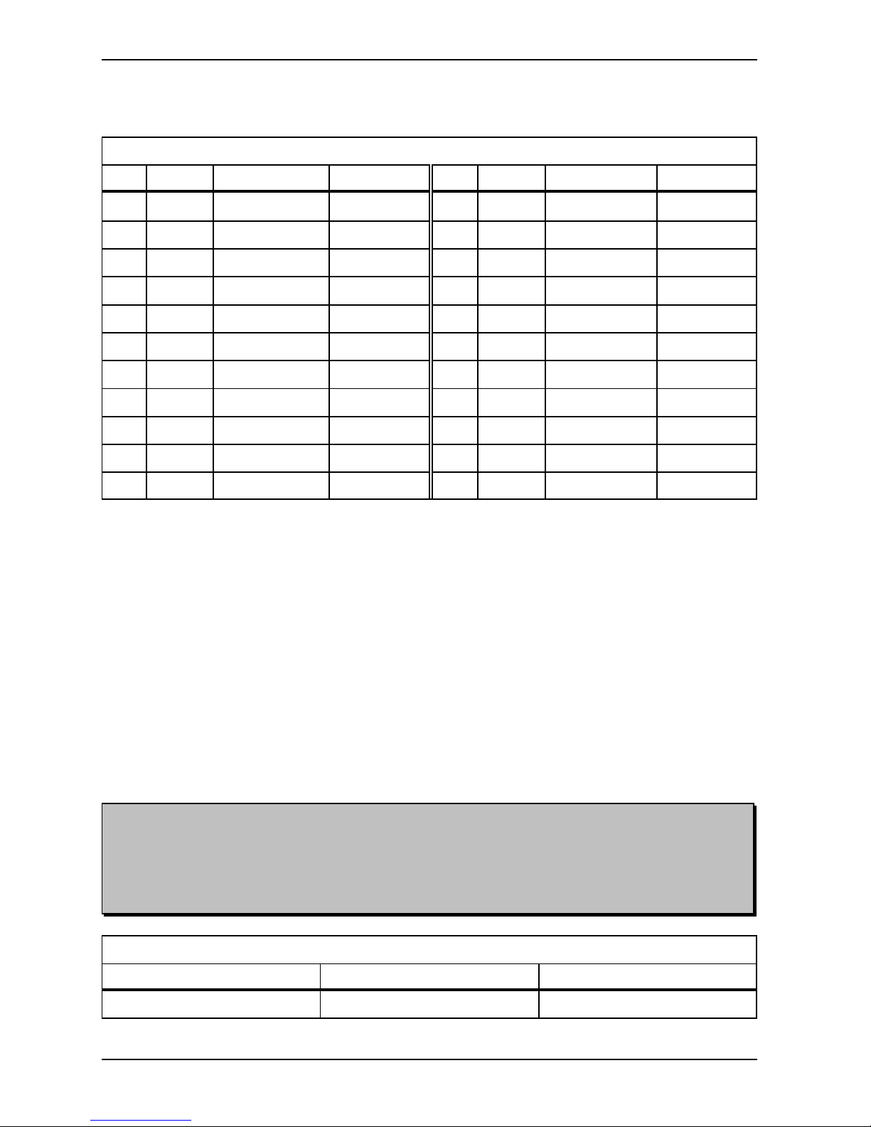
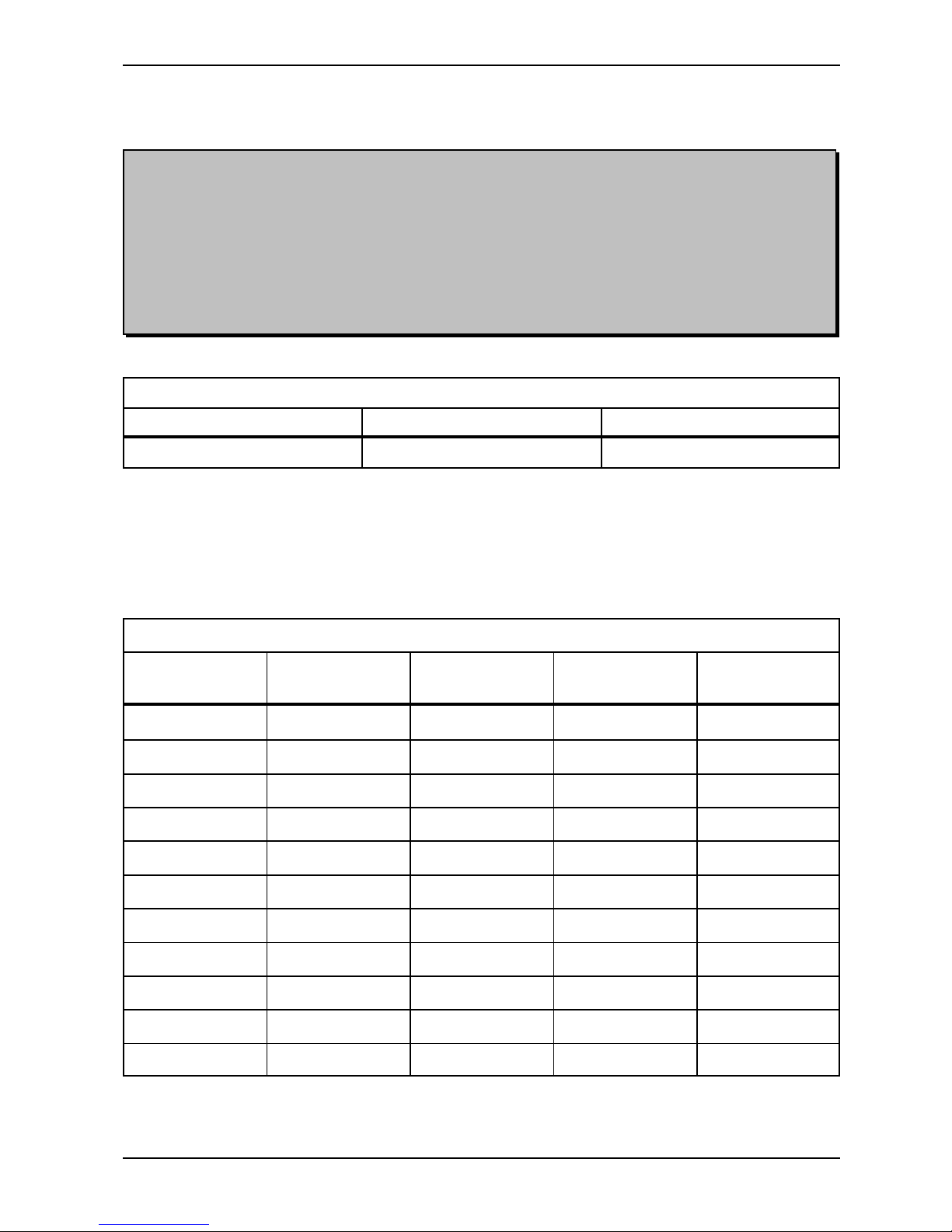
2.8 Lines per Page, Example:
Lines per Page, Example.
Sheet Length,
Inches
Normal LineSpac
6 dot
Normal LineSpac
8 dot
Double LineSpac
6 dot
Double LineSpac
8 dot
4 9 7 6 5
5 11 9 7 6
6 14 11 9 8
7 16 13 11 9
8 19 15 12 11
9 21 17 14 12
10 24 19 16 13
11 26 21 17 15
12 29 23 19 16
13 31 25 21 18
14 34 27 22 19
Page 32

BRAILLO M NORWAY AS B 200
28
Note! The table is made for Page 1 up.
3. SERVICE AND MAINTENANCE
3.1 Troubleshooting
Through proofreading, errors have been found in some of the characters in the text.
The first thing to do is:
Check the characters in the text-file in your computer to find out if the error could come from the text-file
and not from the Braillo Printer. However, if your text-file is OK, a problem has occurred in the Braillo
Printer.
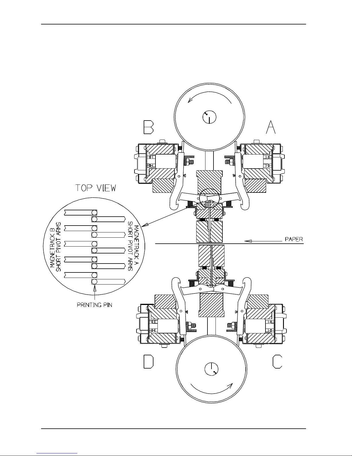
Inside the Printer there are four identical magnet racks, named from A to D. Each magnet rack contains
42 printing mechanisms. There are totally 168 printing mechanisms to choose among when the error
search begins. See figure in chapter 3.2, "Principal Design of Printing Procedure".
As a start, you should run the built-in Test Print. Depending on what kind of errors you have, you should
use different tests.
The essential thing at this stage is to find which magnet rack(s) is causing the trouble.
If there is missing dot(s), use the X-pattern to detect which magnet rack(s) is missing the dot(s).
If there are too many dots, use the full cell lines, or the test pattern on test print no. 4, and the extra dot(s)
will appear in the space between the lines.
However, the best test is ordinary text, if a proofreader is available. To locate the faulty magnet rack(s),
use the Table of Page Sequences.
See figure in chapter 3.3, "Table of Page Sequences".
An example how to use the table:
1 Find the page with the error. (Use the pagination on the printed page). Let us assume that the error
has occurred on page 10. Find the braille cell with the error. The braille cell contains 2 columns
of each 3 (or 4) dots. See figure below.
Here, it is assumed that the error is found in the column with dot 1, 2, 3 (and 7).
2 The Table of Page Sequences shows that page 10 is printed from the top and downwards. From
the same table you can see that this column with dot 1, 2, 3 (and 7) in the braille cell is printed by
a mechanism in magnet rack A.
Braille cell
1 o o 4
2 o o 5
3 o o 6
7 o o 8
Page 33

BRAILLO M NORWAY AS B 200
29
Possible reasons for errors
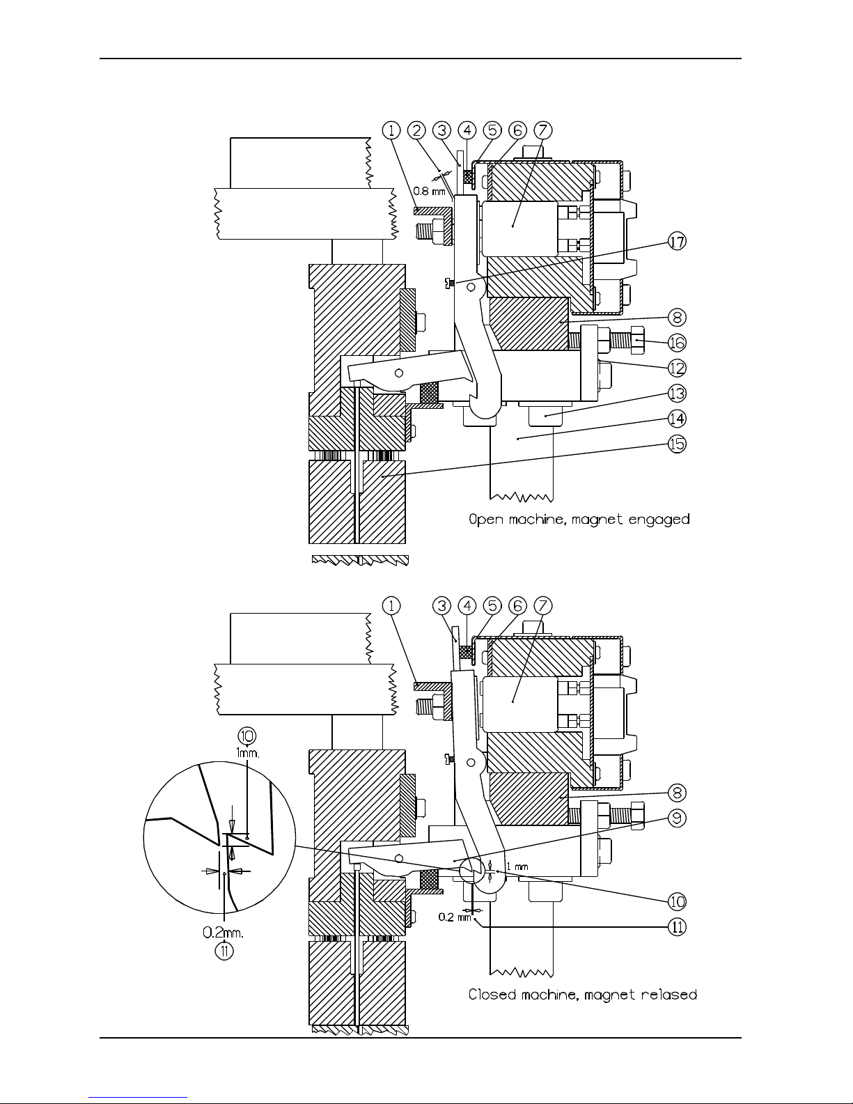
See figures on page 36.
If a dot from a certain printing pin is missing regularly, the reason might be one of the following:
1 - Defect magnet (7).
2 - Broken short pivot arm (9).
3 - The long pivot arm (3) cannot move because of dirt.
4 - The printing pin is stuck because of dirt, causing the short pivot arm (9) to miss the long
pivot arm (3).
5 - Errors on the Magnet Rack Driver Board.
If dots from several printing pins are missing now and then, the reason might be one of the following:
1 - The sponge list (5) is pushing too hard on the long pivot arm (3).
2 - The gap (11) is too large.
3 - The support list (1) has become sticky on the side against the long pivot arms (3), and the
long pivot arm does not move properly.
If there are too many dots on the paper, the reason might be one of the following:
1 - The sponge list (5) is not pressing enough against the long pivot arm (3).
2 - The gap (11) is too small.
3 - The magnet poles have become sticky, and this causes the pivot arms (3) to stick to the
magnet.
4 - The long pivot arm (3) does not move properly.
Control:
To ensure yourself that you have found the right mechanism after a search, you can do the following test:
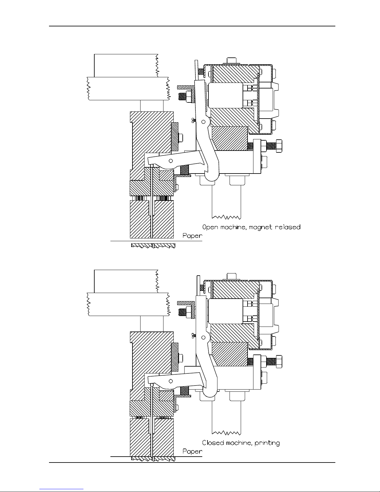
Pull the suspected long pivot arm against the magnet with your finger. (Like the lowest figure on page 37).
At the same time, run a test print. The mechanism with the finger on, will make a column of dots
downwards the paper until you take the finger away. By doing this you can see if this column of dots is
situated on the same place on the sheet as the error is.
Page 34
BRAILLO M NORWAY AS B 200
30
3.2 Principal Design of Printing Procedure
Page 35
BRAILLO M NORWAY AS B 200
31
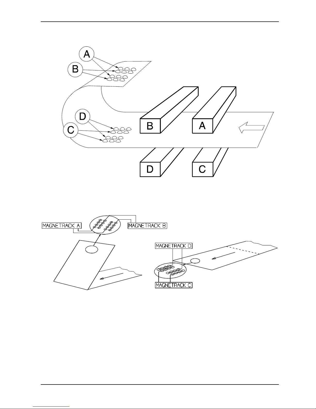
Observe that the same printing mechanism (magnet, long pivot arm, short pivot arm and printing pin)
makes all the dots in a column downwards the page.
Page 36

BRAILLO M NORWAY AS B 200
32
Note! The table is made for Page 1 up.
3.3 Table of Page Sequences
Page layout:
Normal:
Page: 2-4-6-8-10-12-14-16-18-20-22-24-26-28-30 Dot 1-2-3-7 Magnet Rack A
32-34-36-38-40-42-44-46-48-50-52-54-56 Dot 4-5-6-8 Magnet Rack B
1 3 5 7 9 11
/)))))))))3)))))))))3)))))))))3)))))))))3)))))))))3)))))))))1
2 4 6 8 10 12
Page: 1-3-5-7-9-11-13-15-17-19-21-23-25-27-29 Dot 1-2-3-7 Magnet Rack C
31-33-35-37-39-41-43-45-47-49-51-53-55 Dot 4-5-6-8 Magnet Rack D
Z-fold
Page: 1-5-9-13-17-21-25-29-33-37-41-45-49-53 Dot 1-2-3-7 Magnet Rack C
57-61-65-69-73-77-81-85-89-93-97-101 Dot 4-5-6-8 Magnet Rack D
Page: 4-8-12-16-20-24-28-32-36-40-44-48-52-56 Dot 1-2-3-7 Magnet Rack D
60-64-68-72-76-80-84-88-92-96-100-104 Dot 4-5-6-8 Magnet Rack C
1 4 5 8 9 12
/)))))))))3)))))))))3)))))))))3)))))))))3)))))))))3)))))))))1
2 3 6 7 10 11
Page: 2-6-10-14-18-22-26-30-34-38-42-46-50 Dot 1-2-3-7 Magnet Rack A
54-58-62-66-70-74-78-82-86-90-94-98-102 Dot 4-5-6-8 Magnet Rack B
Page: 3-7-11-15-19-23-27-31-35-39-43-47-51-55 Dot 1-2-3-7 Magnet Rack B
59-63-67-71-75-79-83-87-91-95-99-103 Dot 4-5-6-8 Magnet Rack A
Braille cell
1 o o 4
2 o o 5
3 o o 6
7 o o 8
Page 37

BRAILLO M NORWAY AS B 200
33
Note! Do not adjust too tight, the pivot arms may be overstrained and break.
3.4 Magnet Rack, Removal and Refitting
See figures on page 35 and 36.
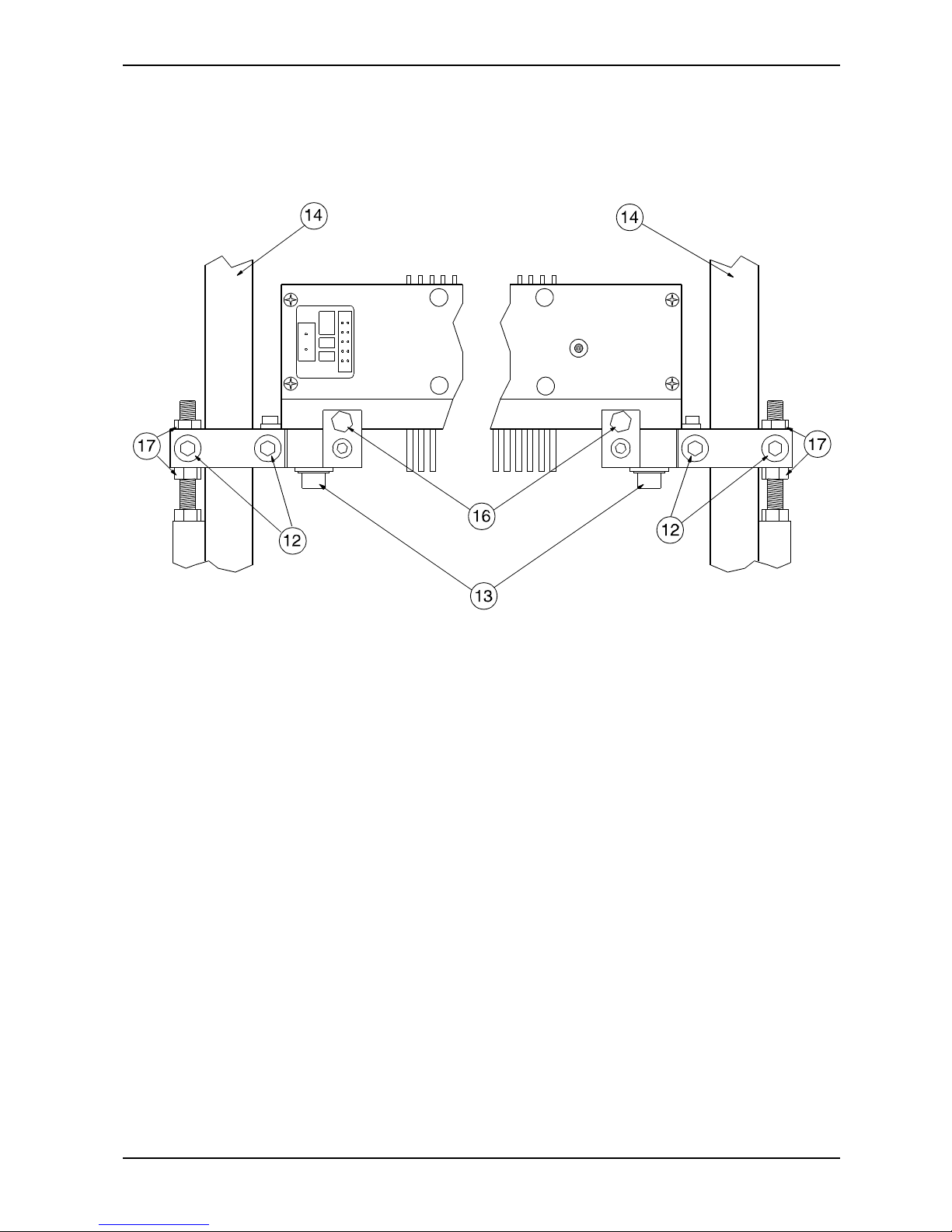
To remove the magnet rack, unscrew two pairs of screws (13), lift out the assembly.
Refitting is the reverse of removal, but observe:
The Printer is adjusted for optimal dot quality when delivered, but different paper quality could make it
necessary to make some adjustments. Our service personnel will adjust the Printer when they are on site.
However, if the Printer should need adjustment and Braillo Norway service personnel is not available, it
should be done like this:
Turn the belt, so the marking at the end of the shafts is pointing in the opposite direction of each other (see
figure below), and lock the shaft, e.g. with a locking wrench.
The magnet rack assembly is fastened on the Printer. The gap (11) should be about 0.2 mm, and should
be adjusted using screw (16). Make sure that the gap (11) is the same at both ends of the magnet rack.
The distance (10) should be about 1.0 mm, but if the braille dots are too weak, you may adjust the magnet
rack tighter in small steps (increase the distance (10)). This is done by loosening the screws (12), and use
the two nuts (17) on the outside of pillar (14) to move the magnet rack up or down. Do this at both ends
of the magnet rack.
Test the Printer for each step of 1/4 rev. of the nuts (17). This will move the magnet rack about 0.3 mm
up or down..
The magnet rack assembly may be moved sideways using two eccentric adjusters at the ends. This is done
at the factory, and should never need to be changed.
Page 38

BRAILLO M NORWAY AS B 200
34
3.5 Magnet Rack, Disassembly, Assembly and Adjusting
See figures on page 36.
Remove the magnet rack as described on page 33.
This is what to do if a magnet (7) is to be replaced, or a complete cleaning is to be done.
Remove the support list (1) and the sponge list (5). Remove the two screws which were hidden under the
sponge list (5). This will make the guide list (8) for the long pivot arm come loose. This, with all the pivot
arms, should be placed aside.
To replace a magnet (7), unscrew the five screws holding the locking list (6), remove the locking list (6),
and pull out the magnet (7) with a narrow pair of pliers.
The magnet can be measured with a multimeter, and if the magnet is OK, the internal resistance should
be between 185 and 220 ohm.
When inserting a new magnet, the magnet should be inserted exactly the same way as the rest of the
magnets. (Observe the small spikes which come out of the soldering on the magnets). If two magnets are
placed with these spikes against each other, the Printer will probably make two dots instead of one when
one of these magnets is engaged. Also make sure that the connectors on the new magnet are placed
exactly in the connectors in the printed circuit board.
The assembly is done in reverse order.
Mount the guide list (8) with the pivot arms on the magnet rack.
Observe the following:
The support list (1) must be adjusted and fastened so the gap between the support list (1) and the long
pivot arms (3) is 0.8 mm, when the long pivot arm is against the magnet. Use a feeler gauge to check this
adjustment.
The sponge list (5) must be adjusted and fastened so the sponges (4) barely touches the top of the long
pivot arms (3) when the magnets are released.
How to replace a long pivot arm:
See figures on page 36.
Remove the magnet rack as described on page 33. Remove the support list (1) and the sponge list (5).
Now, loosen the screws (17). Note! Do not try to unscrew the screws (17) completely. They should only
be loosened about one revolution. Use, e.g. a small screwdriver to slide the pivot arm shaft sideways until
the defect pivot arm is loose. Take it out and replace it with a new one. Put the pivot arm in the position
so that you can slide the shaft back in place. Repeat this for each loose pivot arm until the shaft is approx.
in the centre on the magnet rack. When tightening the small screws (17), pull at the same time the pivot
arm shaft into its slot. And do not over tighten, these screws are fragile!
Assemble the magnet rack as described above.
Page 39
BRAILLO M NORWAY AS B 200
35
3.6 Magnet Rack, Figures
Page 40
BRAILLO M NORWAY AS B 200
36
Magnet Rack, Figures
Page 41
BRAILLO M NORWAY AS B 200
37
3.7 Magnet Rack, Printing Process
Page 42

BRAILLO M NORWAY AS B 200
38
3.8 How to Replace Short Pivot Arms
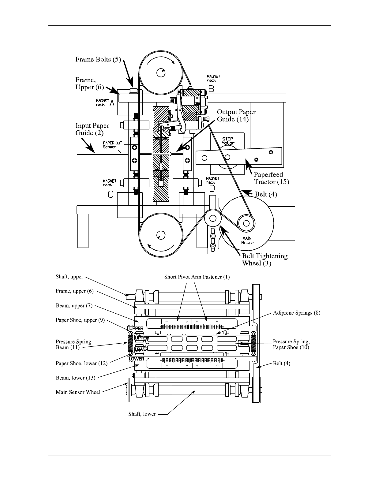
See figures on page 39.
If for some reason the short pivot arms need replacement, (worn or broken) this is the procedure to
follow:
Short pivot arm situated on the upper unit:
1. Remove the magnet rack (the one in front of the defect short pivot arms) as described on page 33.
2. Take off the short pivot arm fastener (1). Pull the short pivot arms straight out of its slot, and the
shaft will come out as well. The short pivot arms shaft consists of two parts, each containing 21
short pivot arms.
3. Put the new short pivot arms back in place, be sure to have the shafts all the way into its slot.
4. Fasten the magnet rack back on place.
Short pivot arm situated on the lower unit:
This procedure will take some more effort to do. This is due to the fact that the printing pin will fall down
if the lower short pivot arms are taken out, and then you cannot get the new short pivot arm back in place.
The procedure here is to take the beam with the short pivot arms out of the Printer before replacing the
short pivot arm. Do as described below:
1. Remove the two upper magnet racks (A and B).
2. Remove the paperfeed tractor assembly (15). Leave the unit on the printer’s frame without
disconnecting the cables.
3. Remove the input paper guide (2).
4. Remove the output paper guide (14).
5. Loosen the belt tightening wheel (3), and remove the belt (4).
6. Loosen the four big bolts (5) on top of the frame (6). Take this bolts all the way out.
7. Now the top part of the frame (6) with the upper shaft must be lifted upwards and placed aside.
Note that the top part of the frame (6) is precisely aligned with the two columns, and could be a
little tricky to lift upwards. The best way is to pull it all the way in one “snap”. If this cannot be
done, it should be wriggled carefully upwards, one side at the time, repeatedly until the unit can
be lifted off.
8. Then, lift the upper beam (7) carefully upwards and place aside. Note that the adiprene pressure
springs (8) are now loose and may fall out. There are eight adiprene springs on the upper unit.
Also take care if there are some steel shims under the adiprene springs, they can easily fall out and
disappear.
9. Lift out the upper paper shoe (9), take out the two blue springs (10), and the two green springs
(11).
10. Lift out the lower paper shoe (12), again take care of the adiprene springs, and eventually the steel
shims.
11. Lift the lower beam (13) out, and the short pivot arm can be replaced like described for the upper
unit above.
12. Assemble in reverse order. To be able to get the belt on correct, see chapter 3.10 “Eccentrics,
Adjustment”.
Page 43
BRAILLO M NORWAY AS B 200
39
Page 44
BRAILLO M NORWAY AS B 200
40
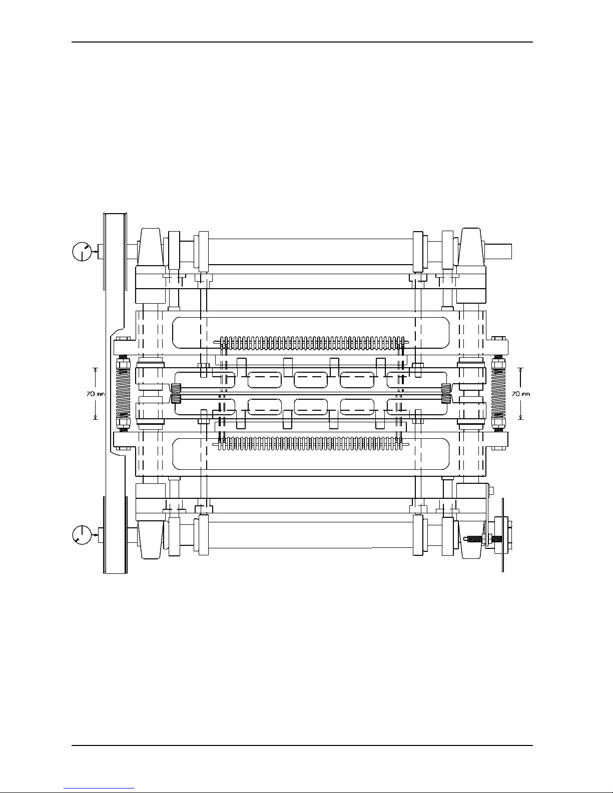
3.9 Return Springs, Adjustment
The adjustment has to be done when the shafts are in this position. See the marks at the end of the shafts
on the figure below.
Page 45
BRAILLO M NORWAY AS B 200
41
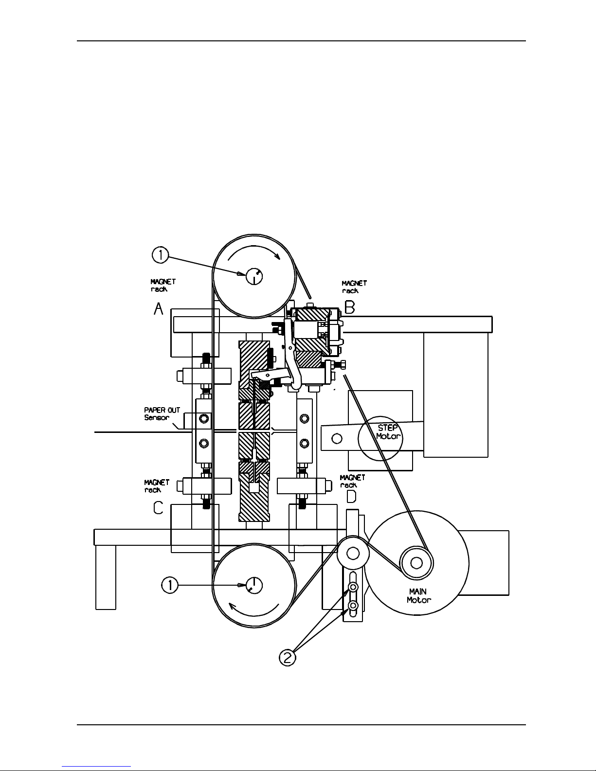
3.10 Eccentrics, Adjustment
After taking off the belt, it is necessary to align the eccentrics.
Put the belt back on, tighten it with the belt tightening wheel (2), and check that the marks at the end of
the shafts (1) are pointing towards each other. See figure below.
If the marks are not aligned like on the figure, it might be necessary to move the belt a notch or two on
one of the wheels.
Page 46
BRAILLO M NORWAY AS B 200
42
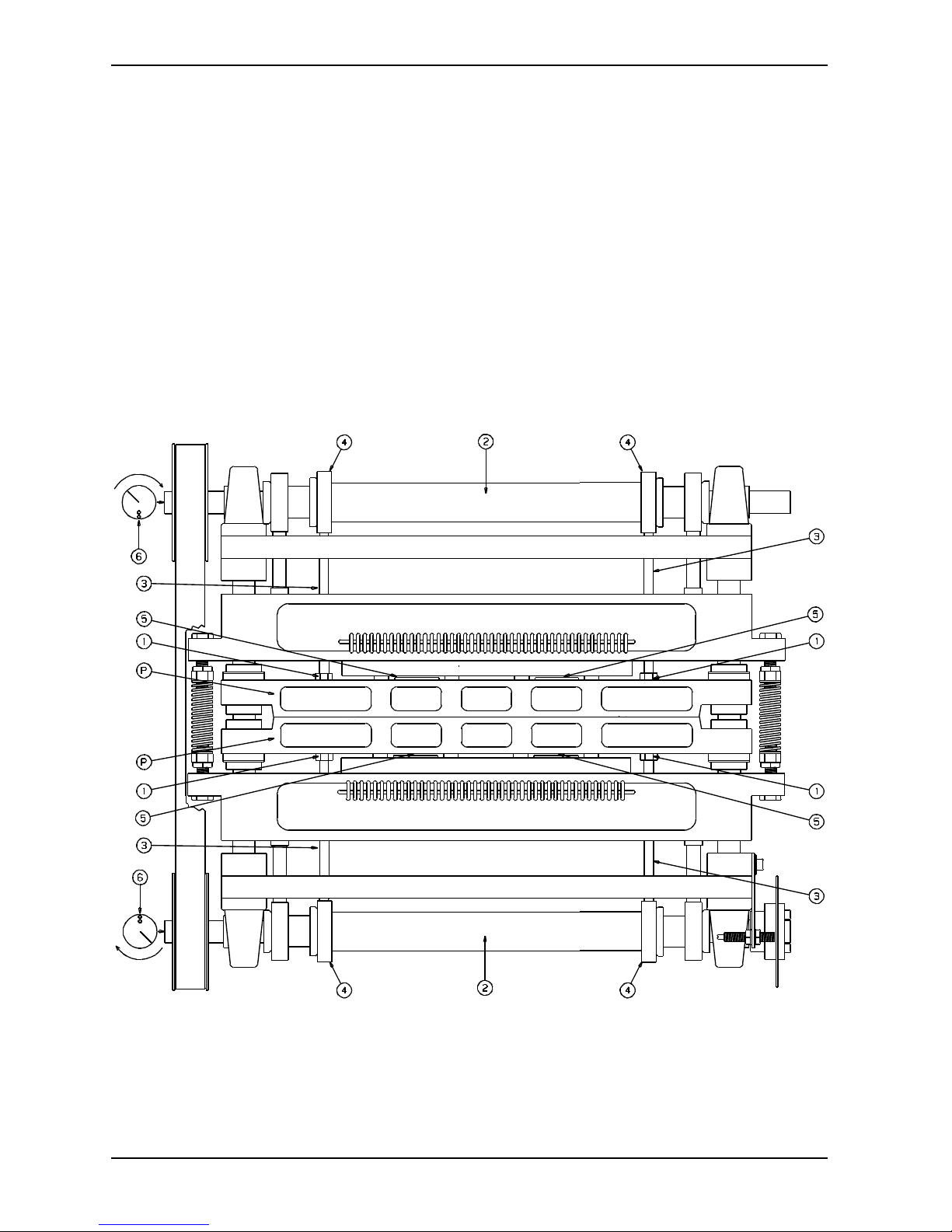
3.11 Paper Shoes, Adjustment
Place a sheet of paper between the paper shoes (P).
Turn the belt so the two points (6) at the end of the shafts (2) is pointing towards each other as shown on
the figure below.
Lock the shafts in this position with a wrench, e.g. at the end of the shaft (2).
Loosen the locking nuts (1), adjust the push rods (3) by turning them. Adjust it against the inner eccentric
bearing (4) until the paper shoes (P) have a light pressure on the paper.
Check that the gap (5) between the press plates and the beam above, is equal on both upper and lower
units.
Secure the push rods (3) with the locking nuts (1).
Page 47
BRAILLO M NORWAY AS B 200
43
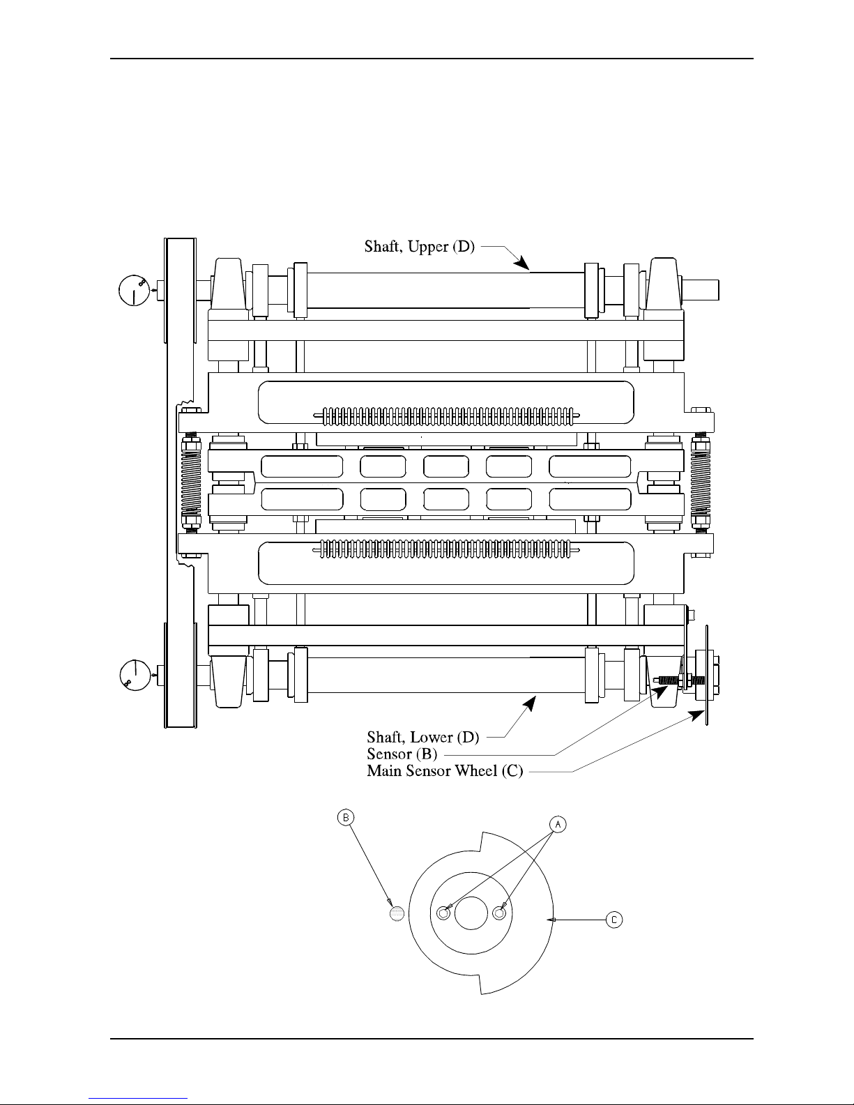
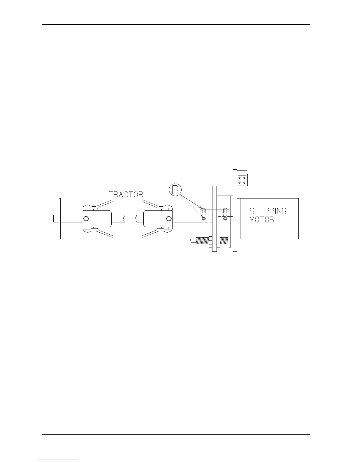
3.12 Main Sensor Wheel, Adjustment
Turn the belt, so the marks at the end of the shafts (D), is pointing towards each other, as shown on the
figure below.
Loosen the screws (A), turn the sensor wheel (C), until the sensor (B) is situated in the middle of the open
part of the sensor wheel. See figure below.
Page 48
BRAILLO M NORWAY AS B 200
44
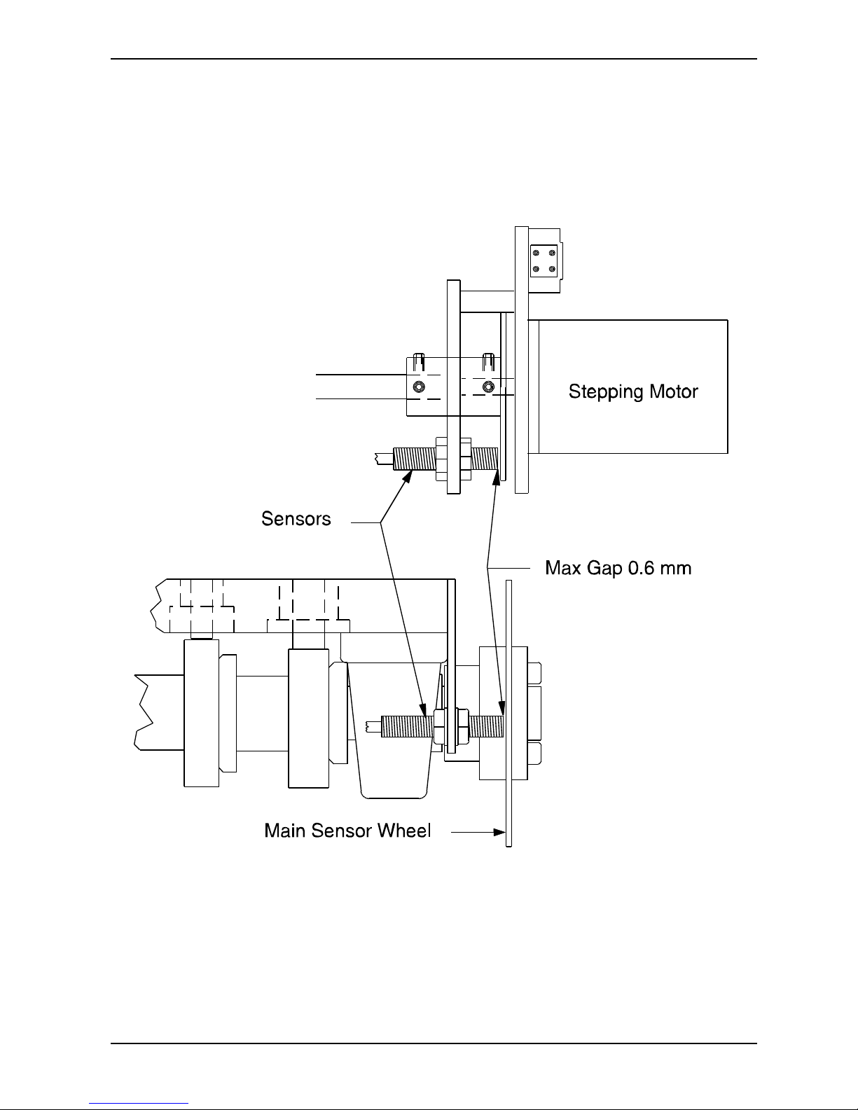
3.13 Paper Feed Mechanism, Adjustment
An adjustment on the relation between the top margin and the bottom margin on a page which is full of
text, could be done like this:
Loosen the tractor feed shaft by unscrewing the two left-hand screws (B) on the sensor wheel.
Note ! Do not loosen the screws for the stepping motor shaft.
Now the tractor feed shaft can be turned forward or backward until the paper is in the wanted position.
Note ! The marks to indicate the positioning of the paper on the paper guide, will not be accurate after
this adjustment.
Page 49
BRAILLO M NORWAY AS B 200
45
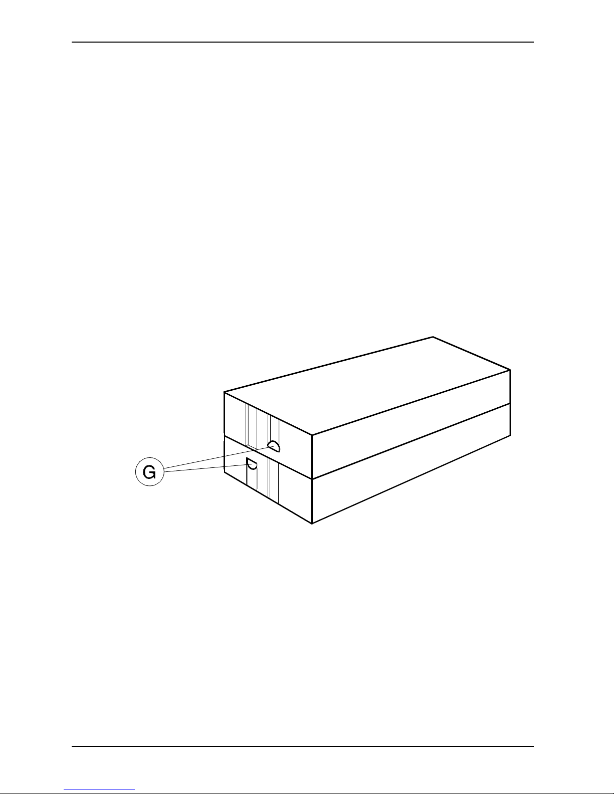
3.14 Inductive Sensors, Replacing and Adjusting
When replacing the sensors, the gap between the sensor wheel and the sensors can be maximum 0.6 mm.
See figure below.
Page 50
BRAILLO M NORWAY AS B 200
46
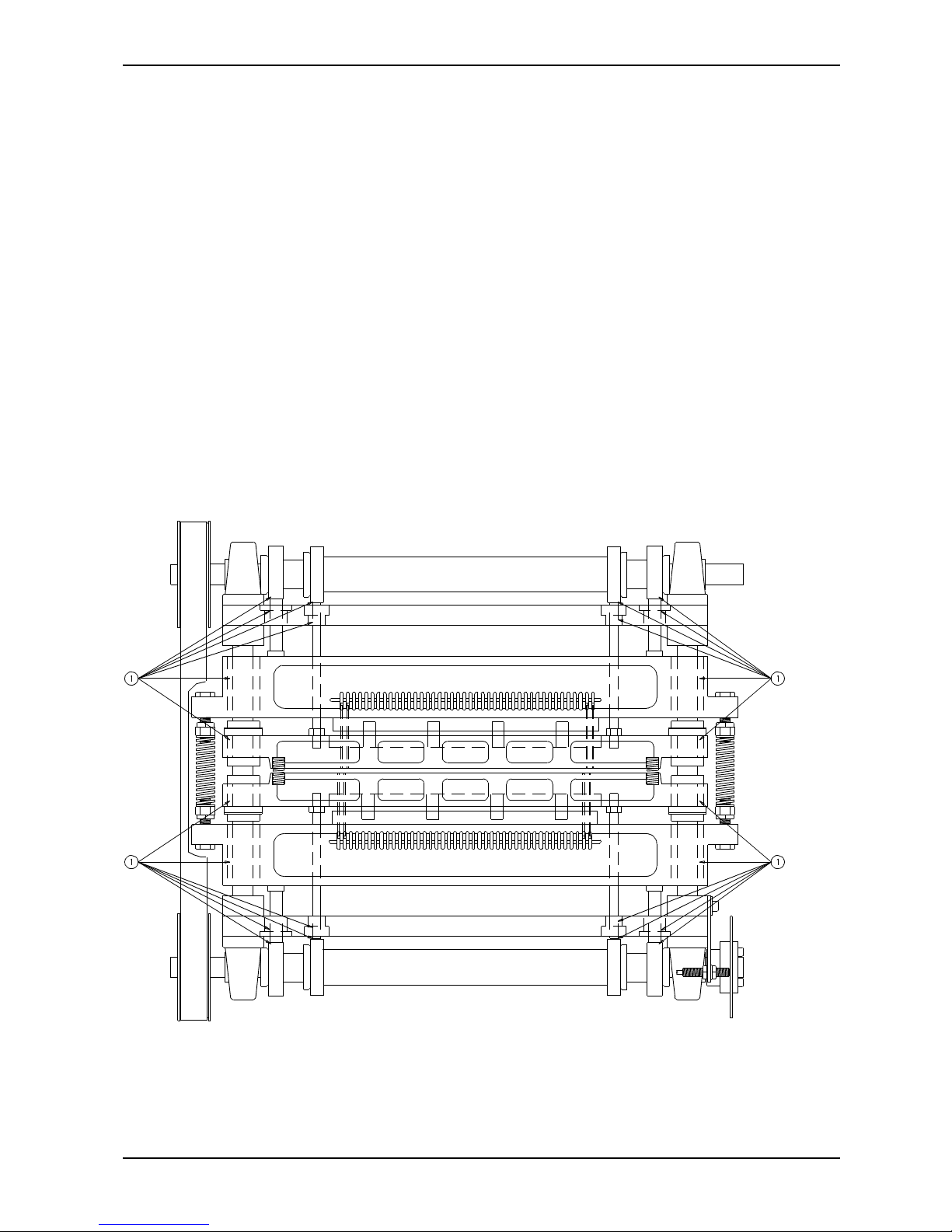
3.15 Paper Sensor, Replacing
The paper out sensor can be replaced like this: Take the paper guide with the sensor out of the Printer.
To open the box, press the two fastening clips (G) simultaneously, and pull the box a little bit open at this
end. Do the same at the other end, and pull the box open.
Replace the sensor.
Page 51
BRAILLO M NORWAY AS B 200
47
3.16 Maintenance
The printing of paper produces paper dust which stick to the mechanical parts of the printing mechanisms
and to the paper guides. Depending on the paper type used, it is necessary to clean the Printer regularly
with a vacuum cleaner, e.g. every 50.000 sheets.
Further, we recommend that at least once every year, the magnet racks are taken apart for more
thoroughly cleaning. Disassembly the magnet racks as described on page 34, and the different parts should
be wiped off with a cloth moisturized with alcohol. The most important areas: The surface on the piece
of iron in the long pivot arm, the magnet poles, the surface on the long pivot arm which lay against the
support list and the support list itself.
Lubrication of Printer.
Bearings (1): Lubricate (grease) after approx. 2000 hours, but: Lubricate if the Printer for some
other reason is disassembled.
Page 52

BRAILLO M NORWAY AS B 200
48
4. SPAREPARTS
4.1 Sparepart List
No. Name Number of parts
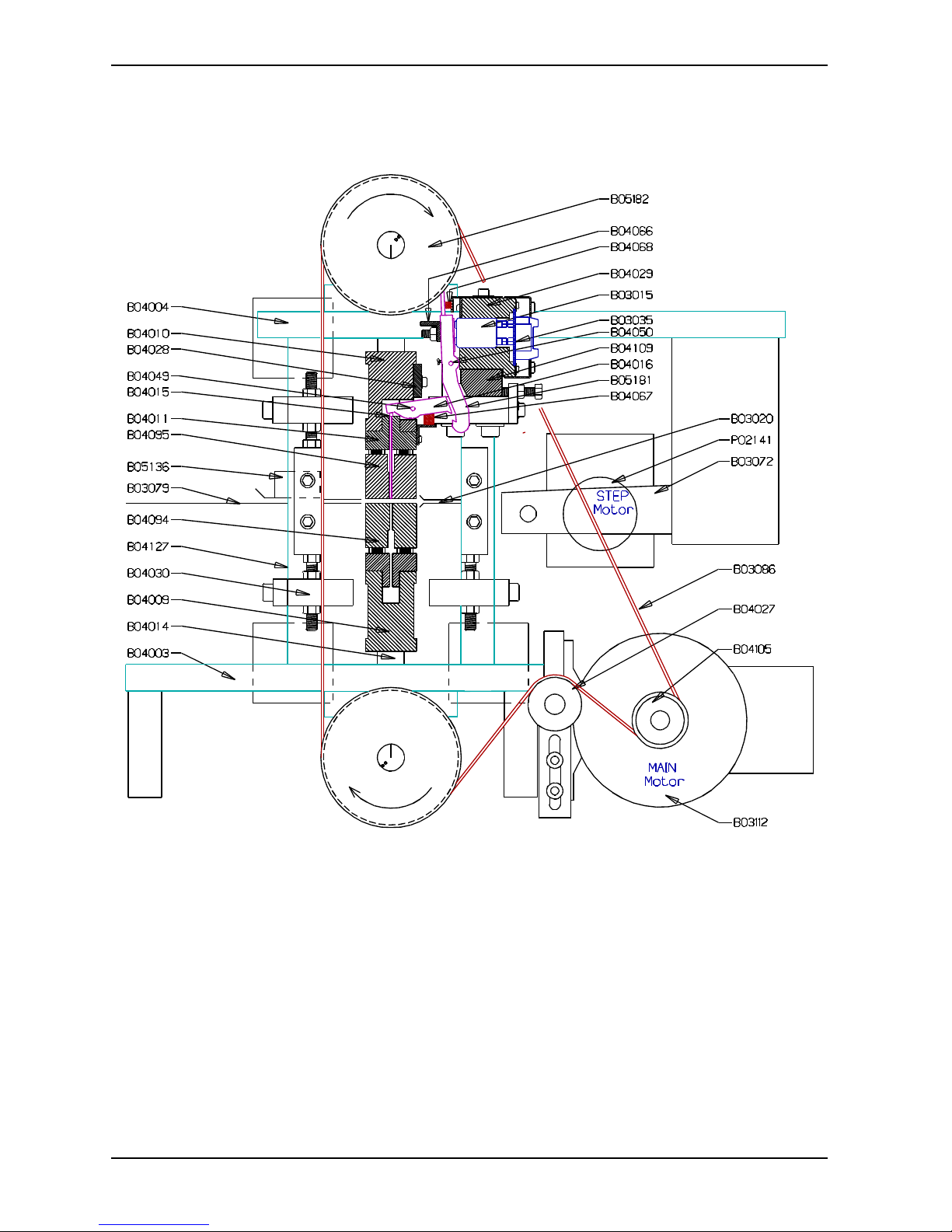
B02141 Stepping Motor, Paper Feed 1
B03015 Magnets 168
B03020 Paper Guide, Inner 1
B03022 Inductive Sensor 3
B03032 Fan, Cover 2
B03035 Magnet Rack Board 4
B03074 Motherboard 1
B03076 Operating Panel 1
B03079 Paper Guide In / Out 1
B03085 Sensor Wheel, Tractor Feed Assembly 1
B03088 Cable, Magnet Rack, flat set 1
B03089 Cable, Magnet Rack, round set 1
B03090 Mains Cable 1
B03091 Power Unit 1
B03111 Main Fuses 1
B03112 Main Motor 1
B03127 Relay, Alarm / Paper Cut 2
B04003 Frame, Lower 1
B04004 Frame, Upper 1
B04005 Shaft, Upper / Lower 2
B04006 Main Bearing with Housing 4
B04007 Bearing Eccentric, Outer 4
B04009 Beam, Lower 1
B04010 Beam, Upper 1
B04011 Rack, Printing Pins 2
B04013 Piston 4
B04014 Columns 2
B04015 Printing Pin 168
B04016 Pivot Arm, short 168
B04020 Pressure Spring 2
B04021 Return Spring 2
B04022 Stroke Ball Bearing, Paper Shoe 4
B04022 Stroke Ball Bearing, Beam 4
B04023 Stroke Ball Bearing, Piston 4
B04027 Belt Tightening Wheel 1
B04028 Short Pivot Arm Fastener 8
B04029 Magnet Rack 4
B04030 Fastener Magnet Rack 8
B04037 Main Sensor Wheel 1
B04044 Pulley, Shaft 2
B04045 Pulley, Motor 1
B04046 Belt 1
B04049 Shaft, Short Pivot Arm 8
B04050 Shaft, Long Pivot Arm, Magnet Rack 4
B04051 Vibration Absorbers 8
Page 53

BRAILLO M NORWAY AS B 200
49
No. Name Number of parts
B04066 Support List, Pivot Arm, Magnet Rack 4
B04067 Sponge List, Short Pivot Arm 4
B04068 Sponge List, Magnet Rack 4
B04072 Push Rod, Paper Shoe 4
B04094 Paper Shoe, Lower 1
B04095 Paper Shoe, Upper 1
B04109 Guide List, Long Pivot Arm 4
B04121 Fuse, Motor (resetable) 1
B04127 Pillar 4
B04131 Stroke Ball Bearing, Rod, Paper Shoe 4
B04132 Bearing, Inner Eccentric 4
B04134 Pressure Spring, Adiprene 16
B05052 Contactor, Motor 1
B05055 Hour Counter 1
B05181 Pivot Arm, Long, Magnet Rack 168
P02181 CPU Power Supply 1
X02029 Fuse, Relays 1.25AF 1
X02548 Fuse, Magnet Rack 3.15AT 4
X02549 Fuse, Step Motor 2.50AF 1
Page 54
BRAILLO M NORWAY AS B 200
50
4.2 Overview Spareparts, Side
Page 55
BRAILLO M NORWAY AS B 200
51
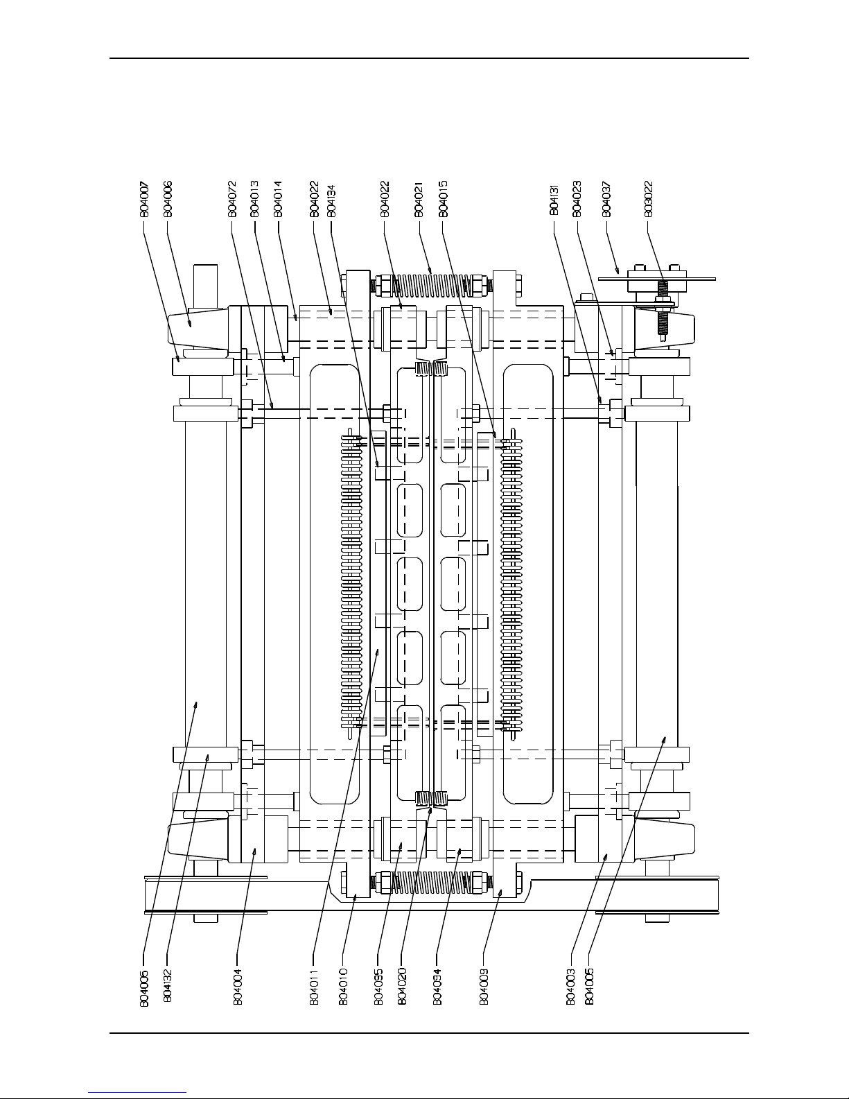
4.3 Overview Spareparts, Front
Page 56
BRAILLO M NORWAY AS B 200
52
5. TECHNICAL SPECIFICATIONS
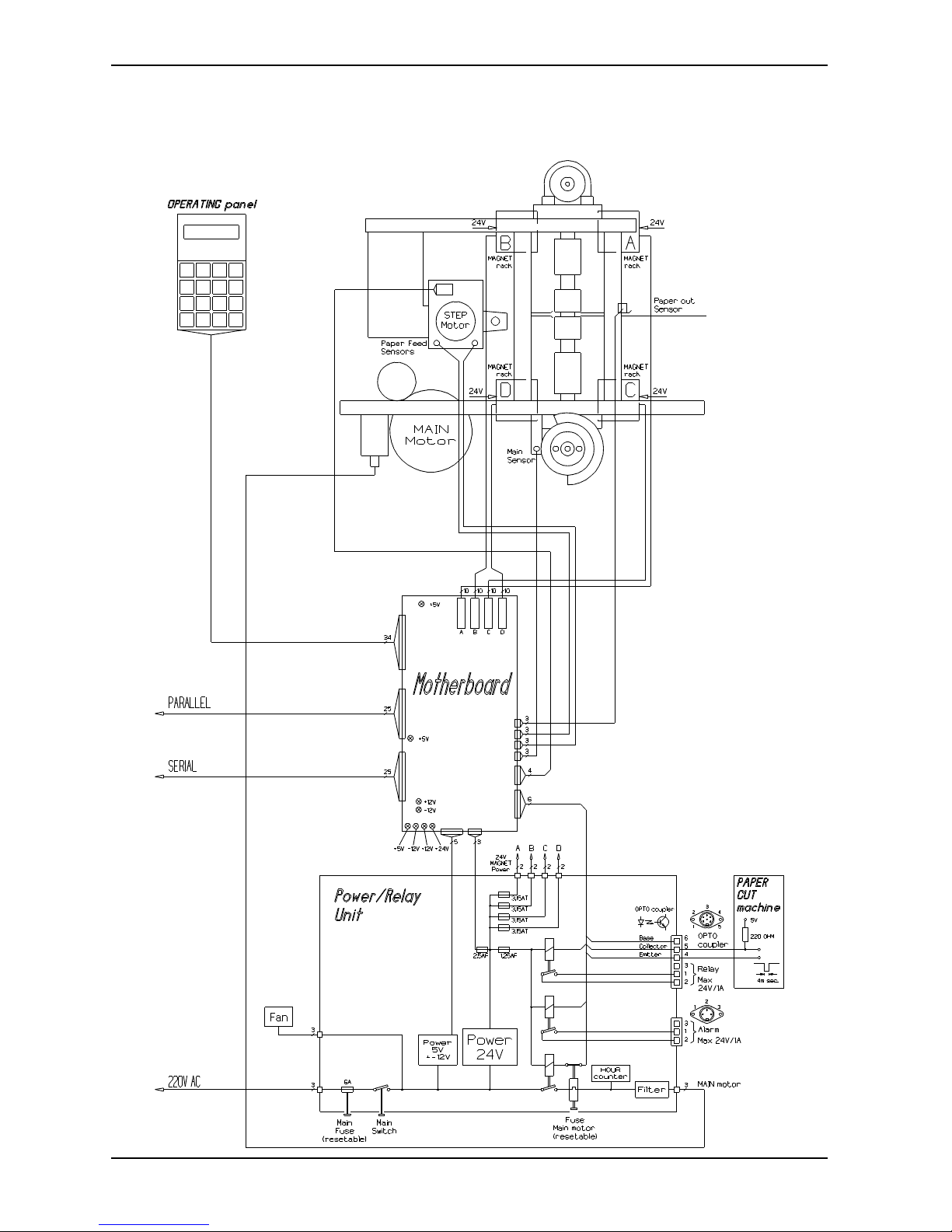
5.1 Cable Connections, Fuses
Page 57

BRAILLO M NORWAY AS B 200
53
5.2 Electric Unit
A Fuse, magnet rack A L Power inlet
B Fuse, magnet rack B M Reset switch, Motor fuse
C Fuse, magnet rack C N Connector, ext. Alarm
D Fuse, magnet rack D O Motherboard
E Main switch P Connector, Braillo Cut
G Connector, operating panel Q Connector, operating panel
H Outlet, Fan R Parallel port
I Outlet, Motor S Serial port
J Hour counter T Fuse, stepping motor
K Main fuse U Fuse, relays
Page 58
BRAILLO M NORWAY AS B 200
54
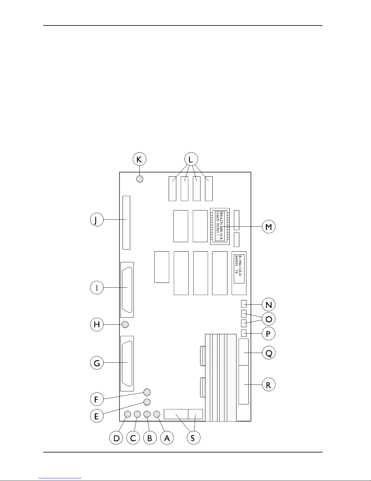
5.3 Motherboard
A: LED, 24 V K: LED, 5 V Magnet racks
B: LED, 5 V L: Connectors, Magnet racks
C: LED, -12 V M: EPROM socket
D: LED, +12 V N: Connector, Paper Out sensor
E: LED, -12 V Serial port O: Connector, Paper Feed sensors
F: LED, +12 V Serial port P: Connector, Main sensor
G: Serial port Q: Connector, Stepping Motor
H: LED, 5 V Parallel port R: Connector, Relays
I: Parallel port S: Power supply input
J: Connector, Operator Panel
Page 59

BRAILLO M NORWAY AS B 200
55
5.4 Pin Configuration Serial and Parallel Port
Data transmission from the computer to the Printer can be done in two ways, either serial or parallel. The
serial goes through an RS 232 C interface, and the parallel is using a Centronics compatible interface. Both
connectors are of the 25 pin D-sub type.
Pin configuration 25 pin male D-sub contact RS 232 C (serial port):
Pin no. 1 FG Frame Ground
Pin no. 2 Tx Transmit data Output
Pin no. 3 Rx Receive data Input
Pin no. 4 RTS Request to send Output
Pin no. 5 CTS Clear to send Input
Pin no. 6 DSR Data set ready Input
Pin no. 7 GND Signal Ground
Pin no. 8 DCD Data carrier detect Input
Pin no. 9 PU + 12V (Logic high) Output
Pin no. 20 DTR Data terminal ready Output
The Printer is only using pin no. 4 (RTS) as a control signal. When this is set to logic low (from the
Printer), the computer must stop sending text immediately. Pin no. 2 (Tx) is used to transmit XON/XOFF
control signals to the computer. The text sent to the Printer is received through pin no. 3 (Rx). All other
outputs from the Printer are set to logic high.
Pin configuration 25 pin female D-sub contact (parallel port):
Pin no. 1 Strobe Input Active low
Pin no. 2 Data 0 Input
Pin no. 3 Data 1 Input
Pin no. 4 Data 2 Input
Pin no. 5 Data 3 Input
Pin no. 6 Data 4 Input
Pin no. 7 Data 5 Input
Pin no. 8 Data 6 Input
Pin no. 9 Data 7 Input
Pin no. 10 Acknowledge Output Active low
Pin no. 11 Busy Output
Pin no. 12 Paper out Output
Pin no. 13 Select Output
Pin no. 14 Not in use
Pin no. 15 Error Output
Pin no. 16 Not in use
Pin no. 17 Frame Ground
Pin no. 18 Signal Ground
Pin no. 19 Signal Ground
Pin no. 20 Signal Ground
Pin no. 21 Signal Ground
Pin no. 22 Signal Ground
Pin no. 23 Signal Ground
Pin no. 24 Signal Ground
Pin no. 25 Signal Ground
Page 60

BRAILLO M NORWAY AS B 200
56
Wiring diagram for the enclosed serial cable
Standard RS 232 C cable, 25-25 pin:
25 pin female 25 pin female
1 FG FG 1
2 TD RD 3
3 RD TD 2
4 RTS CTS, DSR 5,6
5,6 CTS, DSR RTS 4
7 SG SG 7
8 DCD DTR 20
20 DTR DCD 8
Wiring diagram for the serial cable with 9 pins adaptor:
Standard RS 232 C cable, 9-25 pin:
9 pin female 25 pin female
1 DCD DTR 20
2 RD TD 2
3 TD RD 3
4 DTR DCD 8
5 SG SG 7
6,8 CTS, DSR RTS 4
7 RTS CTS, DSR 5,6
Page 61

BRAILLO M NORWAY AS B 200
57
5.5 Technical Specifications
Format:
Chars per line: 10-42 chars.
Sheet length: 4-14 inches
Paper width: 140-330 mm
Page layout: Normal/Z-Fold
Page 1: Up/Down
Printing Type: Single/Double
Line Spacing: Adjustable, Single/Double
Dot: 6/8
Page Length: No Form Feed/Normal/Normal-1 to -9
Braille cell: Standard medium 6 or 8 dot.
Paper Weight: 120 - 180 g/m², Recommended 150 g/m²
Printing Speed: 200 characters per second, Approx. 600 printed pages per hour.
Electrical:
Voltage: Single phase 220V (+/- 10 %), 50Hz
Optional 220V (+/- 10 %), 60Hz
Current: Approx. 5 A max
Fuse Printer: 10 A
Power: Approx. 1000 W max
Communication with the computer:
Parallel on Centronics (25 pin D-sub female), or
Serial on RS 232 C (25 pin D-sub male).
Both are electrical isolated with opto-couplers to prevent noise and ground loops.
Parameters for the serial port:
Baud rate: 150-19200
Parity: No/Odd/Even
Data bit: 7/8
Stop bit: 1/2
Environment:
Temperatures: 15-30°C (60-86°F)
Rel. Humidity: 40-60%
Measurements: Patents:
Height: 580 mm Norway no. 140335
Width: 670 mm Great Britain no. 2040231
Length: 875 mm USA no. 4261663
Weight: 145 Kg Germany no. DE 2850780 C22
Page 62

BRAILLO M NORWAY AS B 200
58
5.6 Addresses and Phone Numbers
Administration/Sales department Braillo Norway AS:
Office: Storgt. 31
Tønsberg
Mail: POB 647
3101 Tønsberg
Norway
Phone: +47 33 31 66 22
Telefax: +47 33 31 66 77
Telex: 70333 brail n
e-mail: [email protected]
Production Braillo Norway AS:
Office: Skolegt. 1
Stjørdal
Mail: POB 93
7501 Stjørdal
 Loading...