

Page 1
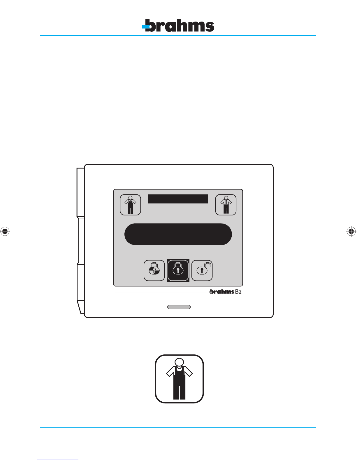
Burglar Alarm System
B2
10
1 2 3 4 5 6 7 8
9
12
Fri
Partial
:
03rd
Armed
30
March
Disarmed
09-05-2011 - 24848602
Technical Manual
1
Page 2

2
Page 3

CONTENTS
1- GENERAL SETTING
INFORMATION Page 5
Introduction ................................................................................. 6
General Information on Setting
the Control Panel - B2UC0002 ......................................... 7
How to access
the setting functions ............................................................ 7
Inputs or Zones .......................................................................... 9
Areas ............................................................................................. 10
Sceneries .....................................................................................10
Arming modes ........................................................................10
Types of Inputs....................................................................... 10
Type of balancing................................................................. 12
- Rolling Shutter Sensor.................................................... 14
- Vibration Sensor ................................................................. 14
- Gong Option ........................................................................ 15
- Tamper ..................................................................................... 15
Outputs ........................................................................................... 16
Activating area ....................................................................... 16
Activating events .................................................................. 16
Output Type ............................................................................. 17
Activation Type ...................................................................... 17
Users ................................................................................................. 18
Priority Levels .......................................................................... 19
2 SETTING
THE CONTROL PANEL Page 21
Main window with the system turned off ............ 22
Learning ........................................................................................ 24
Identification .............................................................................. 25
Device identification .......................................................... 25
Assigning a symbolic name
to the devices ......................................................................... 26
Check module operation ................................................ 27
State of the connected sensors .................................. 28
Erasing a device..................................................................... 28
View Devices State ................................................................. 29
Setting Menu ............................................................................. 30
Input Setting ........................................................................... 31
- Type of Input ........................................................................ 32
- Type of balancing .............................................................. 34
- IR sensor setting ................................................................. 35
- Dual-technology sensor setting ................................ 36
Output Setting ....................................................................... 37
User Setting ............................................................................. 39
Keypad Setting ...................................................................... 41
IR Receiver Setting ............................................................... 42
General Parameters ............................................................. 42
Alarm Parameters ................................................................. 44
GSM Communicator Menu ............................................ 45
- GSM Message Setting .................................................... 45
- Phone Book Setting ......................................................... 45
- Phone Parameters ............................................................. 46
- Sceneries Setting ................................................................48
- Timer Setting .........................................................................49
- Automatic Programs ........................................................49
- Weekly Timer Setting .......................................................50
- Holydays Setting .................................................................50
- Daylight Saving Time Setting .....................................51
Date and Time ........................................................................... 52
Device Test ................................................................................... 53
Input Test ................................................................................... 53
Output Test ............................................................................... 53
Siren Test .................................................................................... 54
Battery Test ............................................................................... 54
Transmission Quality Test ................................................ 54
Event Log ...................................................................................... 55
Default Restore ......................................................................... 57
Change Installer Code ......................................................... 58
Control Panel Version .......................................................... 58
Table of the default settings of all the parameters
.... 59
3
Page 4

4
Page 5

GENERAL SETTING
INFORMATION
1
general setting information
5
Page 6
Introduction
This section of the Installer Manual is NOT intended to define the operating procedures for setting the system
1
parameters (covered in the next chapter), but has the purpose of providing basic information concerning the
characteristics of the system.
Reading this chapter is essential in order to understand the system's performance and be able to take full advantage of its capabilities.
DEU
POR
general setting information
Fig. 1
Choose Language
ENG
ESP
FRA
ITA
ESC
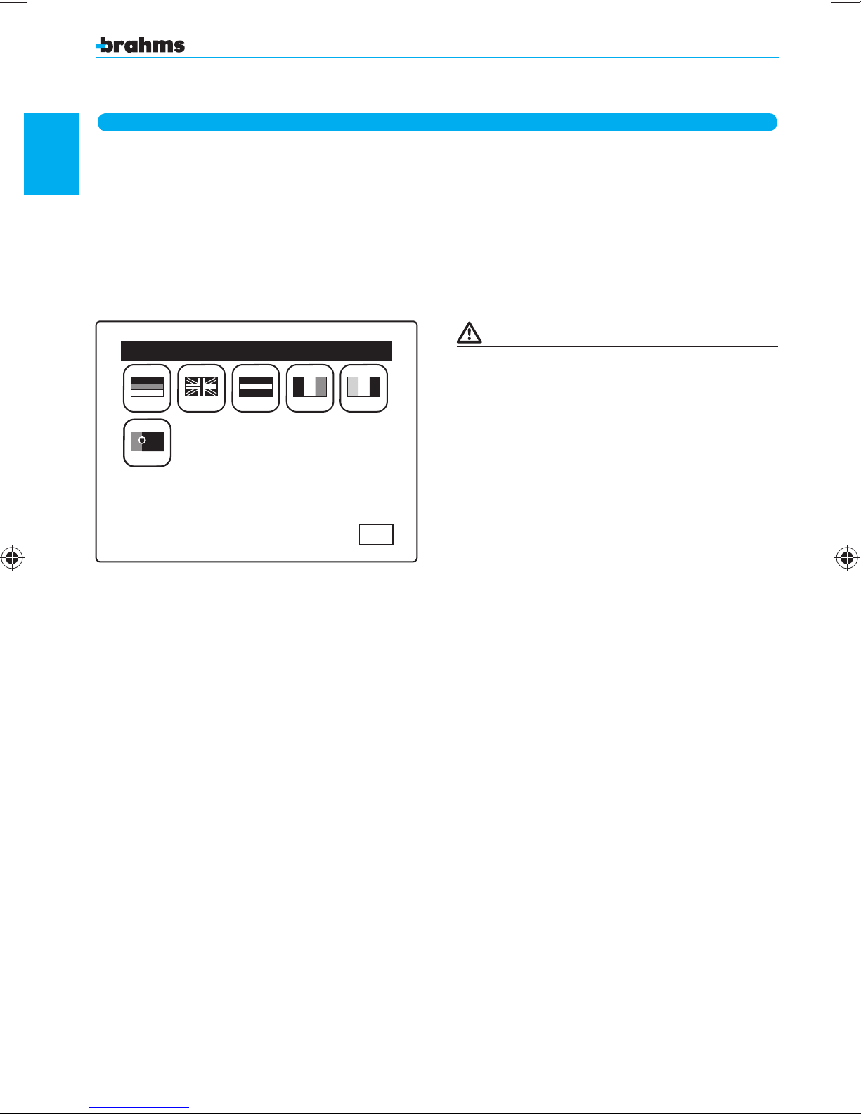
The “Select language” window will appear automatically when the system is powered on or after
there has been a power outage. By pressing the
appropriate icon it will be possible to choose the
system language.
6
Page 7
General Information on Setting the Control Panel - B2UC0002
Fig. 1
1 2 3 4 5 6 7 8 9 10
12
Fri
Partial
:
03rd
Armed
Enter Code
2 1 3 4
30
March
Disarmed
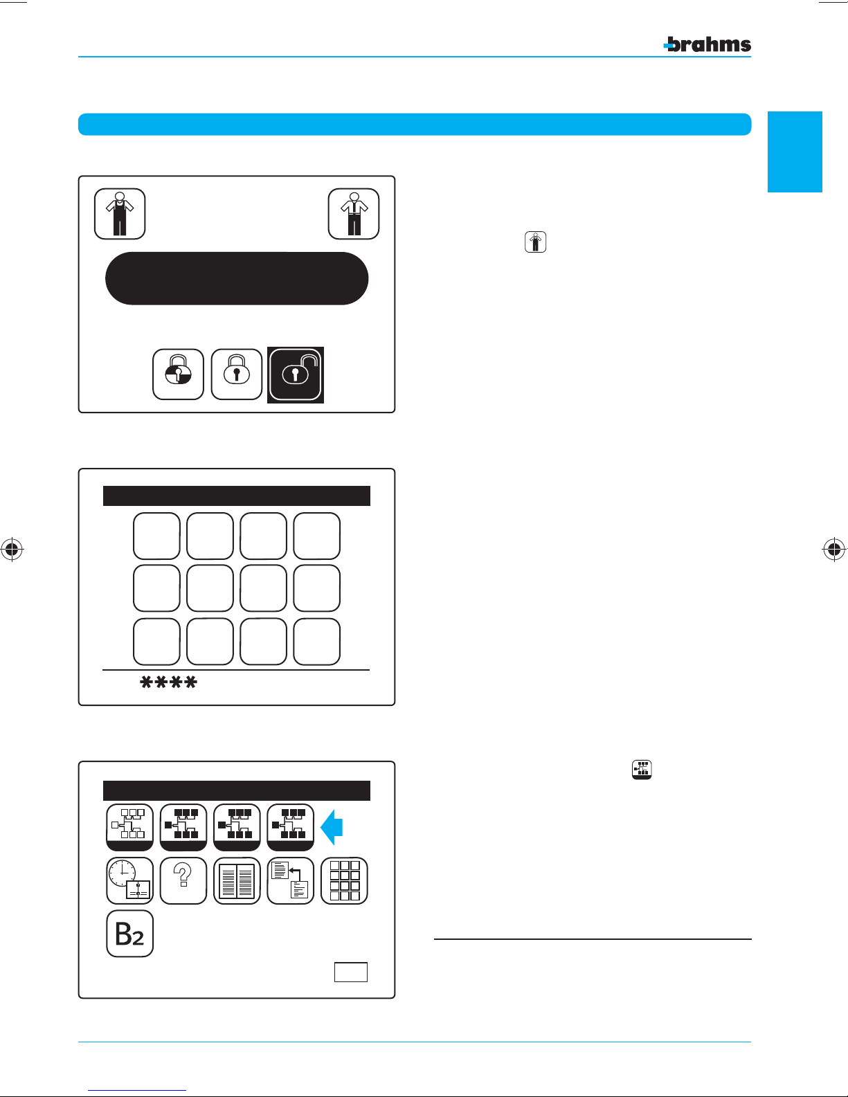
HOW TO ACCESS THE SETTING FUNCTIONS.
With the system turned off, i.e., with no area armed,
press the icon (fig. 1).
Enter the Installer Code, (which at the first start-up
will be 5 6 7 8 fig. 2), to access the Installer Menu
(fig. 3).
1
general setting information
Fig. 2
Fig. 3
6 5 7 8
Esc OK
Learn
1
2
9 0
Installer Menu
S
S
I I I
I
I I
I
Identify
TEST
S
MEM
S
S S S
View
ORY
P
P
P
Setting
P P
P
P
P P
P
P
P
Now press the icon Setting
P
to access the
Setting
Setting Menu (fig. 4).
P
1 2 3
4 5 6
7 8 9
0
If you are in the "Installer Menu", this is signalled on
ESC
the "mechanical" keypads and receivers by all four
LEDs flashing intermittently.
7
Page 8
1
Fig. 4
general setting information
In
In
12V
In
In
12V
0 123456789
0 123456789
0 123456789
0 123456789
Gen. Param.
Setting Menu
Out
Out
Out
Out
Alarm
ESC
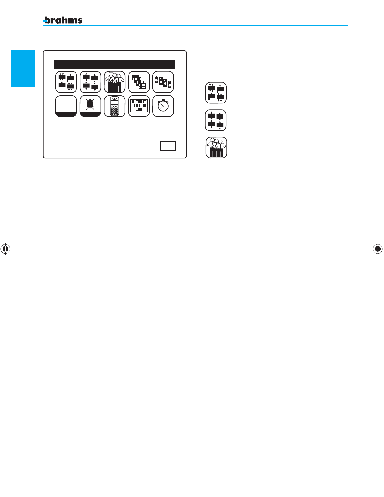
In the Setting Menu, there are a series of icons
that, when pressed, allow access to the setting
parameters of:
In
In
12V
In
In
12V
Out
Out
Out
Out
Inputs
Outputs
Users
These first three items of the menu require further
discussion that will facilitate the setting operations,
while the other menu items will be completely
explained in the chapter on setting the control
panel.
8
Page 9
4 IN Module 01.4
01 Area
Burglar Alarm
Entry Delay=000
Exit Delay =000
NC contact
OK
Fig. 5
Wall IR 01
Input Setting
Input Setting
ESC
In
In
12V
In
In
12V
Inputs or Zones
The definitions of the parameters for each burglar
alarm input or zone is fundamental to the creation of a safe, functional system. The following is a
description of some of the parameters that can be
set for each of them (fig. 5, 6, 7).
For greater immediacy in the viewing of events,
each input and each area can be assigned an alphanumeric description of 14 characters.
It is strategical and highly recommended that you
assign names to the inputs that identify their positions.
This rule also holds for the areas, for which the system
provides a non-modifiable numbering and a description that can be freely assigned to the number.
1
01 Area
Burglar Alarm
Entry Delay=000
Exit Delay =000
Gong Off
OK
Fig. 6
Input Setting
1 IN PW01
01 Area
Burglar Alarm
Entry Delay=000
general setting information
ESC
Exit Delay =000
NC contact
OK
Fig. 7
ESC
9
Page 10
A5
A7
A8 A9
A1
A10
A2
A4
A3
A6
1
Fig. 8
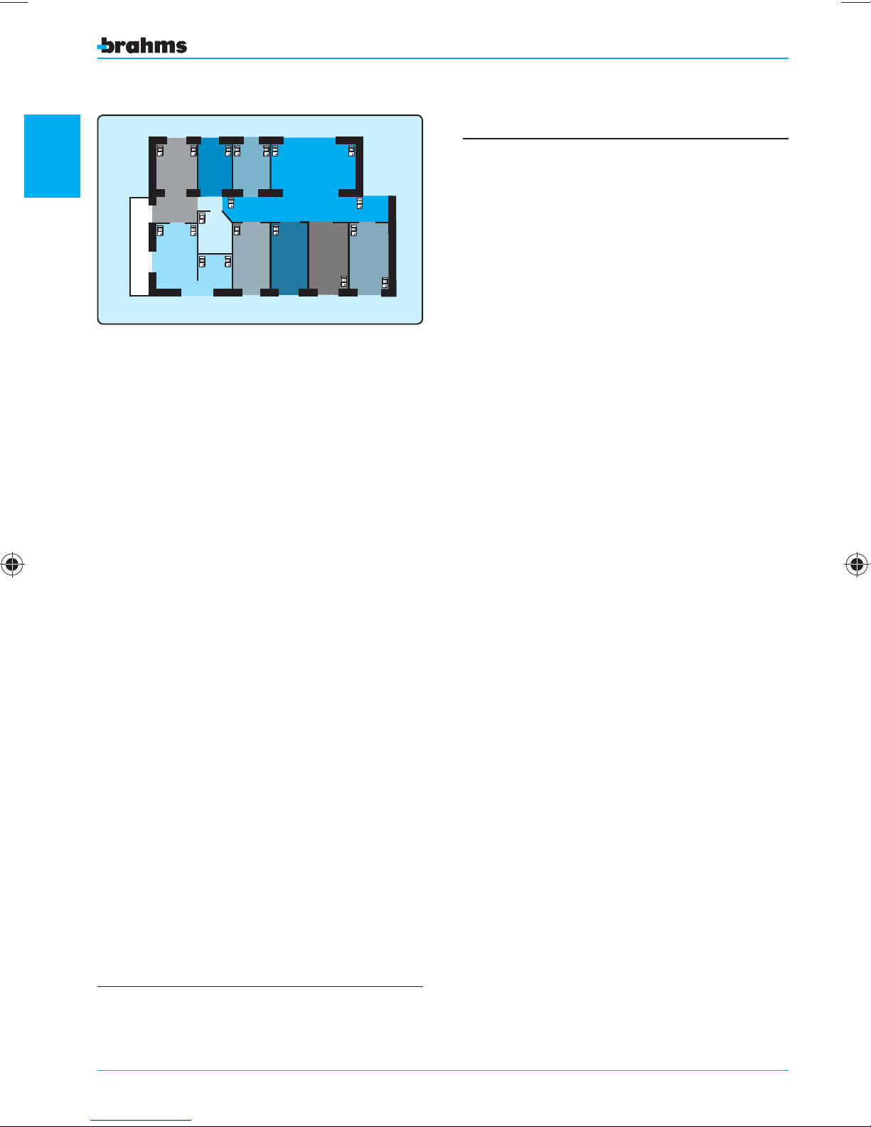
AREAS
It is possible to divide the space to be protected
into areas.
An Area of the system is nothing more than a logical
grouping of inputs.
The subdivision of a system into areas is achieved
simply by assigning one of the ten possible areas
to each input. Subdividing the system into areas is
essential if you plan to:
general setting information
• Arm the system in partial mode as well
• Differentiate the access to particular environments
according to the User Code (see relevant section)
• Have differentiated signals for alarms coming from
different zones (through the setting of the outputs).
To meet these needs, the system can be subdivided
into a maximum of 10 areas (e.g.: fig. 8).
SCENERIES
The term scenery is intended as a combination of
areas that are activated according to set procedures.
During setting, the installer will create the sceneries
containing groupings of areas which, upon activation, will be placed in a state established by the
installer himself.
A name can be assigned to the scenery which is
suggestive of the functions associated with it (“Fence
Sensors”, for example).
A maximum of 10 sceneries can be set.
The default setting establishes that each input (zone)
is assigned to the first Area.
– The Installer (in agreement with the User) must
decide the partial activation mode of the system:
. Through free selection by the User of the areas
to be activated
. Through activation of sceneries predefi ned by
the Installer during setting.
ARMING MODES
“Full” Arming
This arming mode activates all areas of the system
provided that the user, which has entered the code,
is permitted to manage all the areas.
Partial Arming
This arming mode is useful in the event it is necessary to activate only some areas of the burglar
alarm system.
Forced Arming
This mode allows arming of the system even if
one or more devices belonging to the system are
already in a state of alarm. This arming mode forces
the temporary exclusion of the devices in alarm.
TYPES OF INPUTS
“Burglar Alarm” input
If activated, when the system/area is armed, this
input automatically activates the sound alarm signals (continuous sounding of the buzzer) of the
control panel and auxiliary keypads as well as the
visual alarm signals on the control panel, auxiliary
keypads and receivers.
According to the settings, the “Burglar Alarm” event
can activate the sirens and/or one or more outputs
(telephone diallers, for example).
For each input defined as a “Burglar Alarm”
“Entry Delay”
As the name suggests, the “Entry Delay” allows the
user time to enter the protected area and deactivate
the system by entering the proper code, without
activating the alarm system.
The “Exit Delay” allows the user time to exit the protected
area after having entered the activation code.
During the time interval denominated as “Entry Delay”
or “Exit Delay”, the control panel and auxiliary keypads
and “Exit Delay” can be defined.
, an
10
Page 11

emit a continuous buzzer sound to advise the user of
the imminent activation of the alarm system.
The “Entry Delay” and “Exit Delay” apply ONLY to inputs
de ned as “Burglar Alarm”.
“Silent Alarm” or “Anti-aggression” input
If activated, under any system conditions, this input
does NOT activate any visual or sound alarm signal
but can be used to activate one or more outputs for
the activation, for example, of a telephone call using
an external dialler. This function can be useful in the
event the user desires to request outside help (with a
hidden button, for example) without alarming a possible intruder that may be threatening the user.
An input de ned as “Rescue Alarm”
If activated, under any system conditions, this input
activates the lighting of the alarm LED on the keypads
and receivers.
It can be used to alarm those who are inside the protected area, but it can also be set to activate one or
more outputs and can even be directly activated with
keys and keypads (see the “User Manual” also).
“Panic Alarm” input
If activated, under any system conditions, this input
activates the Sirens (which can be set in the window
“Alarm Parameters”) as well as the sound and visual
alarm signals (lighting of the LEDs, sounding of the
buzzers and keypads) of the control panel, auxiliary
keypads and receivers. According to the settings, the
“Panic Alarm” event can activate the sirens and/or one
or more outputs.
“Generic Alarm” input
This type of input is intended to be associated with
sensors or detectors for gas leaks, flooding, fire, etc.
If activated, under any system conditions, this input
activates the lighting of the alarm LED on the keypads
and receivers; it can also be used to activate one or
more outputs.
“Auxiliary Alarm” input
This type of input can also be associated with detectors of the type described above, in order to better
differentiate the functions.
If activated, under any system conditions, this type of
input activates the lighting of the alarm LED on the
keypads and receivers; it can also be used to activate
one or more outputs.
Up to eight types of auxiliary alarms can be used.
“Passage” Burglar Alarm
Input active when the control panel is armed. It
behaves as a delayed input during the system arming
procedure, if a delayed input belonging to any area is
activated; in all the other situations it behaves as an
instantaneous input.
“Pulse Arming Input”
This input is used to arm/disarm the entire system
and thus is no longer available as a burglar alarm
input. If unbalanced, it causes the alternating arming/
disarming of the control panel; this mode is used, for
example, to control the control panel with a remote
control/gate opener. Contrasting commands given
from the control panel, keypads and receivers have
priority over commands given from the “Key” zone.
1
general setting information
“Tamper Alarm” input
If activated, under any system conditions, this
input activates the Sirens as well as the sound and
visual alarm signals (lighting of the LEDs, sounding
of the buzzers and keypads) of the control panel,
auxiliary keypads and receivers. According to the
settings, the “Tamper Alarm” event can be used
to activate one or more outputs.
“Level Arming Input”
This type of input is used to arm/disarm the entire
system and thus is no longer available as a burglar
alarm input. If unbalanced, it arms the system; and
it disarms the system when balanced. Contrasting
commands given from the control panel, keypads
and receivers have priority over commands given
from the “Key” zone.
11
Page 12
Alarm
contact
Z1
Alarm
contact
Z1
Alarm
contact
Z1
Alarm
contact
Z1
Standby condition
open input
Line cut
not detected
Alarm condition
input closed at earth
Short circuit on line
as input
closed at earth
Standby condition
input closed at earth
Line cut
as open input
Alarm condition
open input
Short circuit on line
NOT DETECTED
Alarm
contact
Z1
Alarm
contact
Z1
Alarm
contact
Z1
Alarm
contact
Z1
Input/event type Activated if
Activates
Sirens
Activates Sound
Signal
Activates Visual
Signal
Burglar Alarm Armed Area YES YES – Intermittent YES YES
1
Silent Alarm Always NO No NO YES
Rescue Alarm Always NO No YES YES
Panic Alarm Always YES YES – Intermittent YES YES
Tamper Alarm Always YES YES – Intermittent YES YES
Generic Alarm Always NO No YES YES
Auxiliary Alarm 1-8 Always NO No YES YES
“Passage” Burglar Alarm Armed Area YES YES – Intermittent YES YES
(1) The activation of the sirens in case of “Burglar Alarm” and “Panic Alarm” can be set in the window “Alarm
Parameters”.
(2) The sound alarm signals are emitted by the control panel and auxiliary keypads through the intermittent sounding
of the buzzer. For the control panel and each keypad, however, it is possible to set whether or not said signal should
be emitted (see Keypad Setting and User Menu).
(3) The visual alarm signals are emitted by the control panel, through the relative icon appearing on the display, and by
the auxiliary keypads and receivers, through the lighting of the alarm LED.
(4) The activation of one or more outputs can be set by associating them to the relative events (see Output Setting).
general setting information
Activates
Outputs
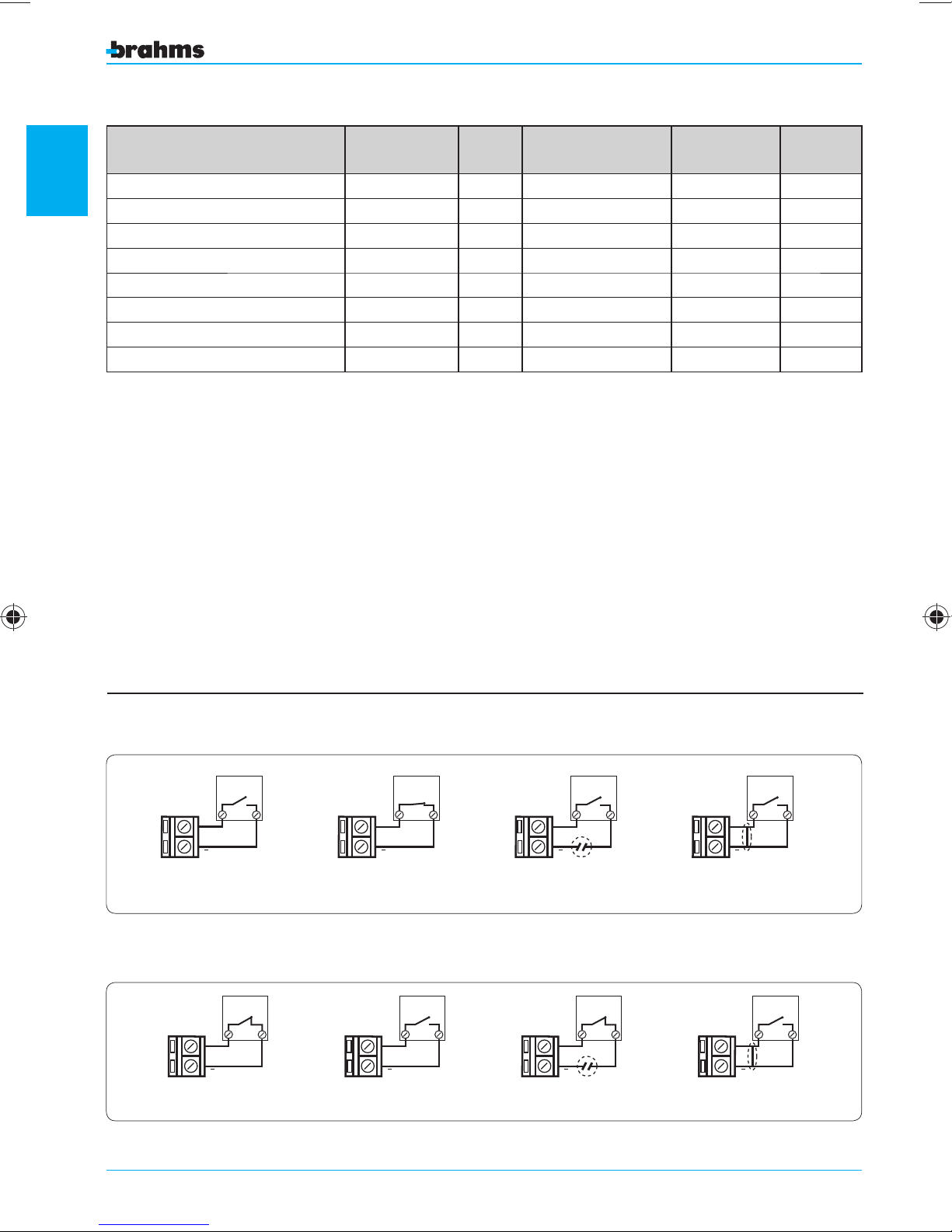
TYPE OF BALANCING
The following pages describe all the types of balancing that can be associated with each input com-
prising the burglary alarm system. This operation is
essential in order to prevent false alarms.
Normally Open - Schematic diagram for the connection of a device with Normally Open alarm contact.
Normally Closed - Schematic diagram for the connection of a device with Normally Closed alarm contact.
12
Page 13
Alarm
contact
Z1
RFL
Alarm
contact
Z1
RFL
Alarm
contact
Z1
RFL
Alarm
contact
Z1
RFL
Standby condition
input closed at earth
with resistance RFL=2.2KΩ
Line cut
open input alarm
Alarm condition
open input
Short circuit on line
Input closed at earth
Tamper Alarm
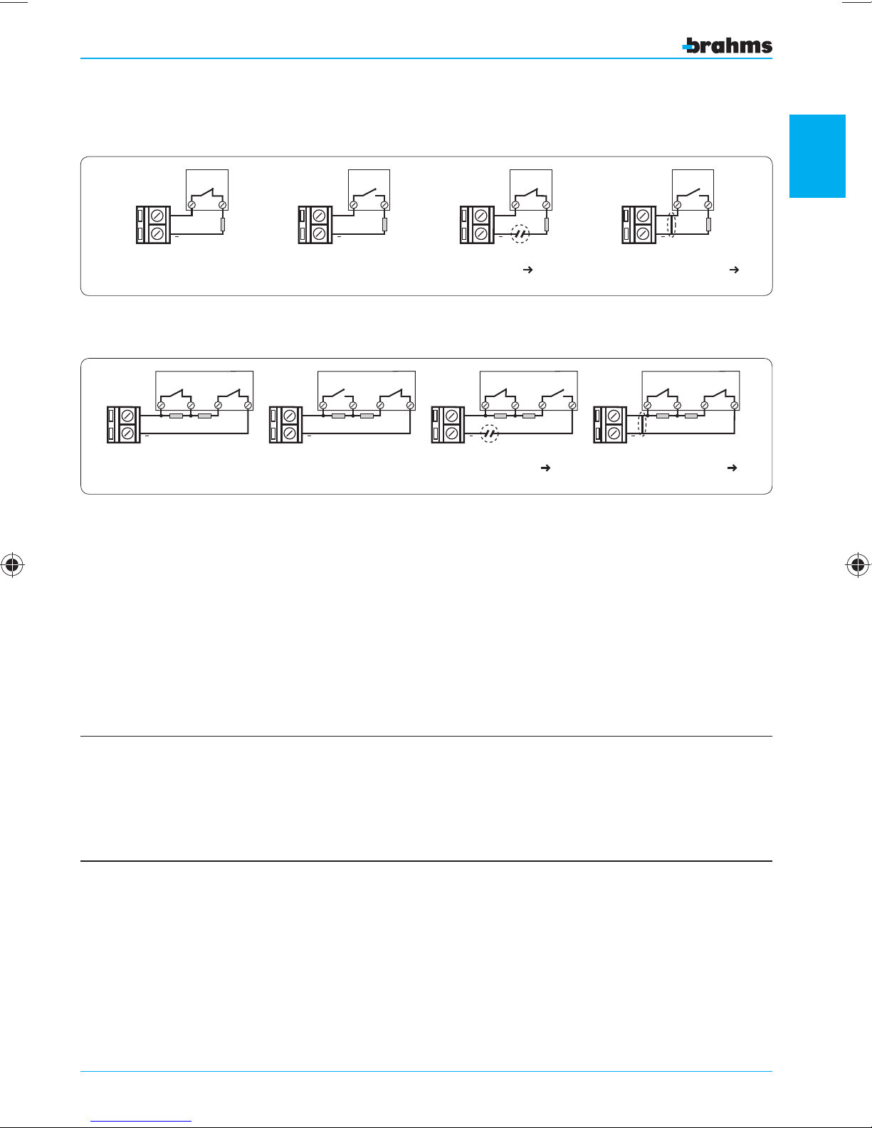
One Resistance Mode - Schematic diagram for the 'one resistance mode' connection of a device with
Line cut
open input
Tamper Alarm
Standby condition
input closed at earth
with resistance RFL=2.2KΩ
Alarm condition
input closed at earth
with resistance RFL+RA = 4.4KΩ
Short circuit on line
Input closed at earth
Tamper Alarm
Alarm
contact
Z1
Tamper
contact
RFL
RA
Alarm
contact
Z1
Tamper
contact
RFL
RA
Alarm
contact
Z1
Tamper
contact
RFL
RA
Alarm
contact
Z1
Tamper
contact
RFL
RA
Normally Closed alarm contact.
Two Resistance Mode - Schematic diagram for the 'two resistance mode' connection of a device with
Normally Closed alarm contact.
1
general setting information
The control panel has the following default settings for the balancing of sensors connected to the input modules:
• input of the powered 1-input modules: one resistance mode.
• input of the 4-input modules: NC contact.
• The set type of balancing must be consistent with the type of physical connection made for the devices connected to the input modules, in order to prevent serious malfunctioning of the security system. Thus, if sensors
are to be connected to the input modules with balancing different from the default setting, it is essential to set
the “type of balancing” parameter appropriately in order avoid false alarms.
• The connection of the sensors without balancing (NO, NC), although permitted by the control panel, does not
allow recognition of a short circuit or cutting of the detection line which is accidental or intended to neutralize
the burglar alarm. It is therefore not advisable to use it for the connection of burglar alarm sensors, while it is
admissible for the connection of sensors connected to inputs set as “Generic Alarm
” or “
Auxiliary Alarm
”.
13
Page 14

ROLLING SHUTTER SENSOR
This type of selection allows the direct connection
(without requiring an interface card) to the Brahms
CFSST prewired cable contact input modules for
1
protection of the rolling shutters.
The “Rolling Shutter Sensor” inputs require the setting of the following parameters.
Pulse Number
This determines the number of the pulses that must
be reached in order to cause the alarm condition.
Time Interval
This determines the duration of the time interval in
which must be recorded the set number of pulses
in order to cause the alarm condition.
general setting information
VIBRATION SENSOR
This type of selection allows the direct connection
(without requiring an interface card) to the Brahms
SVAMB and SINZI breaking sensor input modules.
The “Vibration Sensor” inputs require the setting of
the following parameter.
Pulse Length
It determines the minimum amplitude that the
pulse coming from the sensor must have in order
to be considered as an alarm.
This parameter has no affect on the inputs defined
differently from “Rolling Shutter Sensor”.
To prevent serious malfunctioning, use exclusively
Brahms CFSST cable contacts (or equivalent) if contacts of this type are to be connected directly to the
input modules. For the connection of other types
of devices, contact the Brahms Technical Service
Department.
14
This parameter has no affect on the inputs defined
differently from “Vibration Sensor”.
To prevent serious malfunctioning, use exclusively
Brahms SVAMB and SINZI breaking sensors (or
equivalent) if contacts of this type are to be connected directly to the input modules. For the
connection of other types of devices, contact the
Brahms Technical Service Department.
Page 15
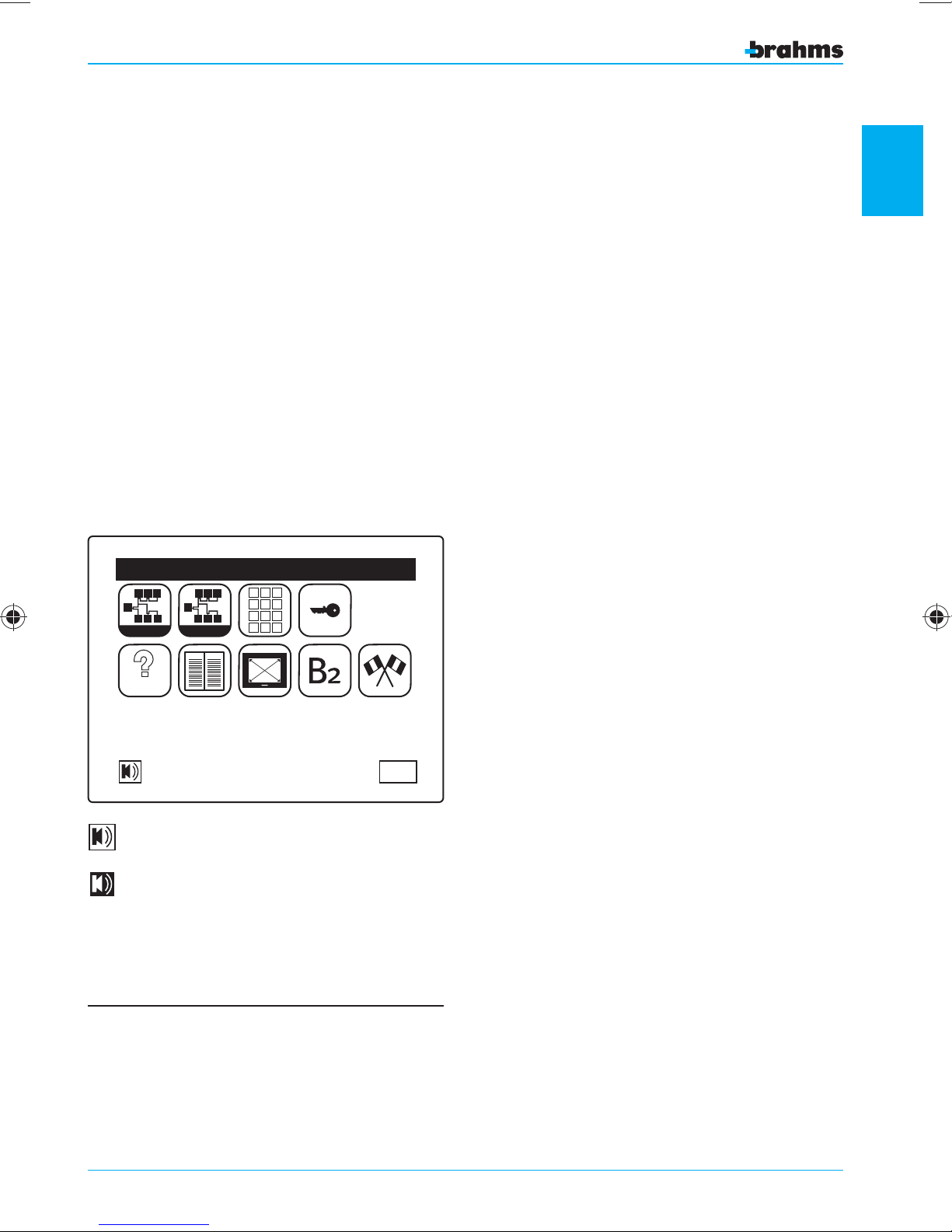
GONG OPTION
An attribute which can be assigned to “Burglar
Alarm” inputs with a type of balancing other than
“Rolling Shutter Sensor” and “Vibration Sensor”.
A “Gong” input, if activated
when the control panel
is armed, behaves as a normal burglar alarm input.
If activated when the control panel is disarmed, it
activates the buzzer of the control panel, without
reproducing the sound emission on the buzzers of
the keypads.
The activation of the GONG option requires that,
when the item is enabled in the setting menu of the
individual inputs, the buzzer of the control panel
must be activated in the window “User Menu” (see
User Manual).
TAMPER
This option allows the installer to choose whether
or not the B2MI0401
input modules should manage the tamper signal separately from the alarm
contact. This is useful if the tamper signal is to be
managed separately using magnetic contacts with
wires or terminals dedicated to this type of signal.
1
User Menu
S
S
S
S S S
Visualizza
P
P
P
Setting
MEM
P P
P
123
456
789
P
ORY
0
S
TEST
ESC
Buzzer off
Buzzer on
The setting of these parameters must be consistent
with the type of physical connection made for the
devices connected to the input modules, in order
to prevent serious malfunctioning of the security
system.
general setting information
15
Page 16
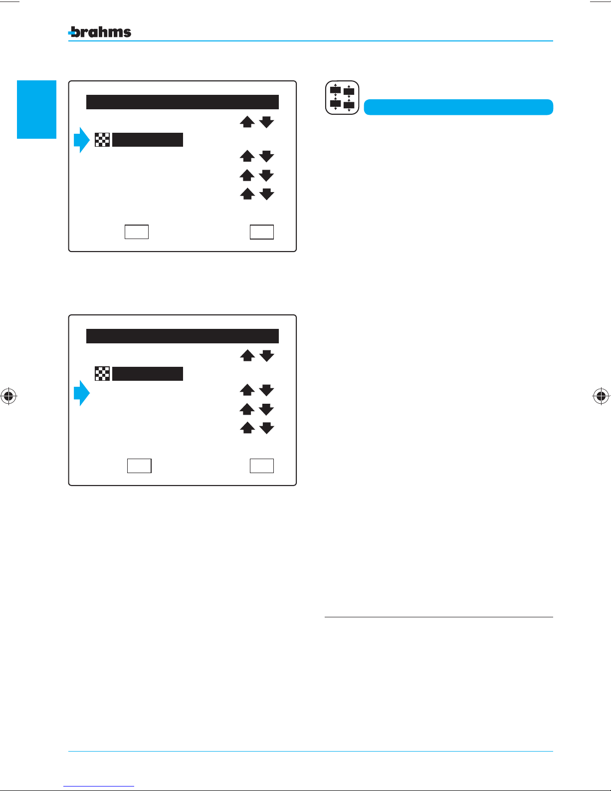
1
Output Setting
2 OUT Module
01.2
Areas Not Ready
Pulse 005
Out
Out
Out
Out
8 9 10 7 1 2 3 4 5 6
For greater immediacy in the viewing of events,
each output can be assigned an alphanumeric
description of 14 characters.
Outputs
Normally Active
Fig. 9
2 OUT Module
general setting information
Generic Alarm
Level 000
Normally Disactive
OK
Output Setting
01.2
OK
ACTIVATING AREA
For the outputs as well, it is also possible to select
ESC
8 9 10 7 1 2 3 4 5 6
ESC
the group of areas for which these will be activated
(fig. 9).
If, for example, the areas 1-5 are selected, then the
output will be activated only if the event has been
triggered by an input belonging to the areas 1-5.
ACTIVATING EVENTS
The 4 outputs on the card of the power supplier or
those belonging to the 2-output expansion modules can be activated by events such as faults,
alarms and system states that can also be differentiated by the area of the system in which the event
was generated (fig. 10).
Not all events are affected by the area, as shown in
the table provided on the following page.
Fig. 10
16
The 4 outputs located on the power supplier are
provided with a standard setting that automatically
associates each output with an event:
PW OUT 01 Burglar Alarm
PW OUT 01.2 Tamper Alarm
PW OUT 01.3 Fault
PW OUT 01.4 Disarmed
Page 17
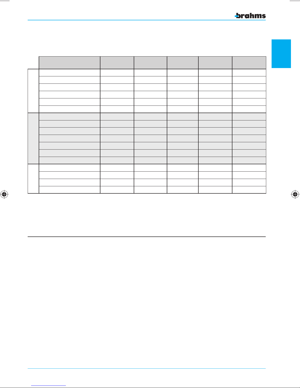
The table below provides the complete list of
events that can be selected from the display (fig. 10)
and their interaction with the areas.
Events Activated if
No events Always NO NO NO NO
Accessories Aux PW Fault Always NO NO Intermittent YES
Bus PW Fault Always NO NO Intermittent YES
PW Fault Always NO NO Intermittent YES
FAU LT S
Battery Fault Always NO NO Intermittent YES
Fault (any type of fault) Always NO NO Intermittent YES
Burglar Alarm Armed Area YES YES Intermittent YES
Silent Alarm Always YES NO NO NO
Rescue Alarm Always YES NO NO YES
Panic Alarm Always YES YES Intermittent YES
ALARMS
Tamper Alarm Always YES YES Intermittent YES
Generic Alarm Always YES NO NO YES
Auxiliary Alarm 1-8 Always YES NO NO YES
Partial Armed Always NO NO NO YES
Area Not Ready for Arming Disarmed Area YES NO NO YES
Disarmed Area Disarmed Area YES NO NO YES
STATES
Area with Temp. Excluded Zones Armed Area YES NO NO NO
(1) The activation of the sirens in case of “Burglar Alarm” and “Panic Alarm” can be set in the window “Alarm Parameters”.
(2) The sound alarm signals are emitted by the control panel and auxiliary keypads through the intermittent sounding of the
buzzer. For the control panel and each keypad, however, it is possible to set whether or not said signal should be emitted
(see Keypad Setting and User Menu).
(3) The visual alarm signals are emitted by the control panel, through the relative icon appearing on the display, and by the
auxiliary keypads and receivers, through the lighting of the alarm LED.
Conditioned
by the Areas
Siren
Activation
Activates
Sound Signal ⁽²⁾
Activates
Visual Signal ⁽³⁾
1
general setting information
OUTPUT TYPE
Level
- For outputs associated with alarms, the output
remains activated for the “Alarm Time” and can be
deactivated like a siren.
- For outputs associated with faults or control panel
states, the output remains activated for the entire
time the triggering event is present.
Pulse
The output is activated by the presence of the
event, but remains active only for the set time.
The output, however, will remain operative even if,
during that time, the cause that triggered the activation of the output is restored.
TYPE OF ACTIVATION
Normally Disactive
The output is normally inactive. It is activated when
an event is present. The relay coil of the outputs is
always de-energized, and it is energized when there
is an activating event.
Normally Active
The output is normally active. It is deactivated when
an event is present. The relay coil of the outputs is
always energized, and it is de-energized when there
is an activating event.
17
Page 18
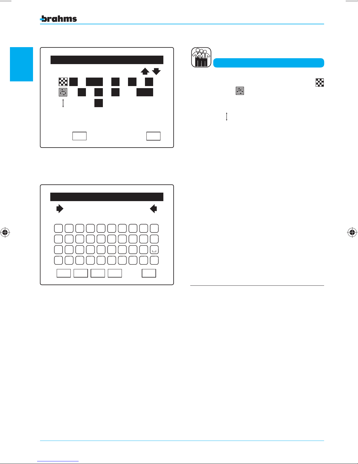
1
User Setting
Marco
1 2 3 445 6 7 8 9 10
1 2 3 4 5 6 7 8 9 10
2
4
3
1
OK
ESC
Users
Each User can be assigned a group of areas
and/or sceneries
that will be the only ones the
User can arm and/or disarm ( g. 12).
It is also possible to assign each user a
from 1 to 4
2
4
, which will allow or not the user to
3
1
priority level
perform a series of operations, as speci ed in the
tables on the next page.
Fig. 12
general setting information
A B C D E F G H I J
K L M N O P Q R S T
U V W X Y Z ' . 0 1 2 3 4 5 6 7 8 9
CAP
Fig. 13
Enter User Name
Marco
BkSp
DEL
OK
Each User can be assigned a symbolic description
to ensure certain identification (fig. 13), and the
description will also be used in recording each
access.
ESC
The default setting establishes that:
• all areas/sceneries are assigned to all User Codes;
• the highest Level of Priority (4) is assigned to all
User Codes (4)
• at the first start-up there is only one User Code,
which will be “1 2 3 4”
• at the first start-up the Installer Code, i.e., the sin-
gle code that allows access to the Installer Menu,
will be “5 6 7 8”.
The setting of the assigned areas, the assigned
sceneries and the level of priority for each User is
carried out inside the Installer Menu; the assigning
of the Keypad Codes and Key Codes for each User
is carried out inside the User Menu by a User with
Priority Level 4.
18
Page 19
PRIORITY LEVELS
User with priority level 4 - Can be considered the system administrator because he has access to all the functions that
can be managed by the User.
User with priority level 3 - Is the normal user of the system that can arm and disarm the system but does not require
access to particular functions.
User with priority level 2 - Is a User with restrictions that allow him only to arm the system (the cleaning personnel, for
example).
User with priority level 1 - Can only leave evidence of his passage in the event log (the security service, for example).
Action Level 4 Level 3 Level 2
Full or partial Arming/Disarming
of the sceneries or associated areas
Alarms Off YES YES NO
Forced Arming YES YES NO
Alarm Memory Reset YES YES NO
Access to the User Menu YES YES NO
YES YES Arming only
1
A code set with priority level 1 does not cause any action; only the valid typed data is memorized.
(1) The alarms are silenced by any operation (turning on or off, turning on partially, etc.) validly carried out by a User
with Priority Level 2, 3, 4, or through the appropriate control located on the main window in the presence of one
or more alarms.
(2) This occurs in the case in which the automatic arming option is not selected (in the menu “General Parameters”),
otherwise the forced arming will be automatic. The forced arming can be done with a code having Priority Level 3
or 4 using the dedicated command in the window that displays the inputs already in alarm before the arming; the
forced arming of one or more areas or the entire system entails the temporary exclusion of the inputs already in a
state of alarm before the arming. The forced insertion of one or more areas or the whole system entails the temporary
exclusion of the inputs connected to the alarm before the insertion, with the exception of inputs configured with an
“Output Time” other than 0, as described on page 32.
Functions executable inside the User Menu and accessible only to Users
with Priority Level 3 and 4.
Action Level 4 Level 3
Viewing the State and Temporary Exclusion of Inputs YES YES
Viewing the Event Log YES YES
Setting the Date and Time YES NO
Changing User Codes of others / Registering Keys of others
Changing own User Code / Registering own Key
Deleting User Codes YES NO
Input Test YES YES
Siren Test YES YES
Battery Test YES YES
YES NO
YES YES
general setting information
19
Page 20

1
general setting information
.
Page 21

SETTING THE CONTROL PANEL
2
setting the control panel
21
Page 22
2
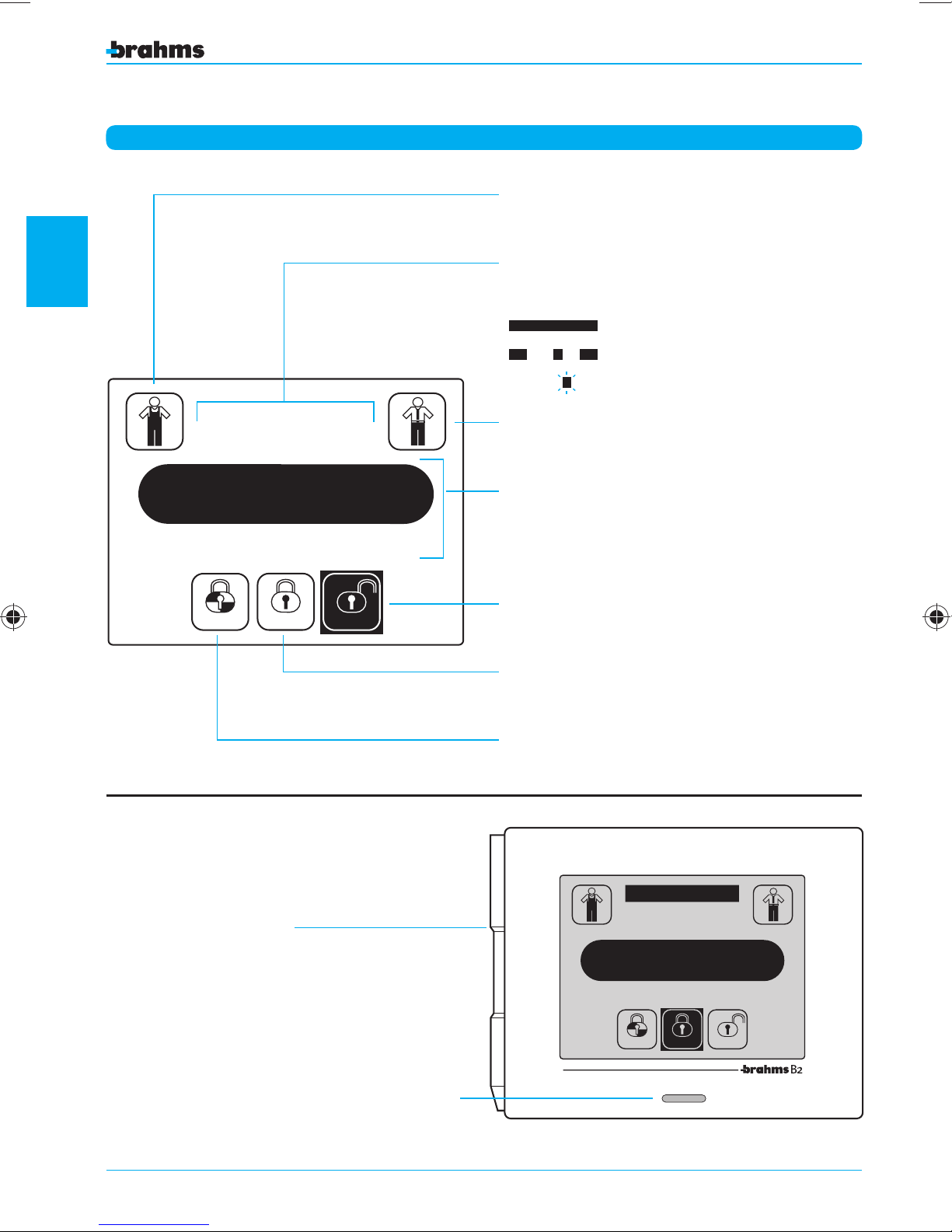
Main window with the system turned off
Installer Menu access
State of Areas display
1 2 3 4 5 6 7 8 9 10
1 2 3 4 5 6 7 8 9 10
1 2 3 4 5 6 7 8 9 10
1 2 3 4 5 6 7 8 9 10
All areas deactivated
All areas activated
Areas partially activated
Areas not ready or in alarm
Fri
setting the control panel
1 2 3 4 5 6 7 8 9 10
12
Partial
:
03rd
Armed
30
March
Disarmed
User Menu access
Date and Time display
System Disarmed Indicator/Button
System Armed Indicator/Button
System Partially Armed Indicator/Button
Pen for touchscreen
Button/LED always lit.
Pressing the button activates the backlighting of
the screen (the back lighting is activated automati-
cally after the touch-screen is pressed)
22
1 2 3 4 5 6 7 8
12
Fri
03rd
Partial
:
Armed
10
9
30
March
Disarmed
Page 23
1 2 3 4 5 6 7 8 9 10
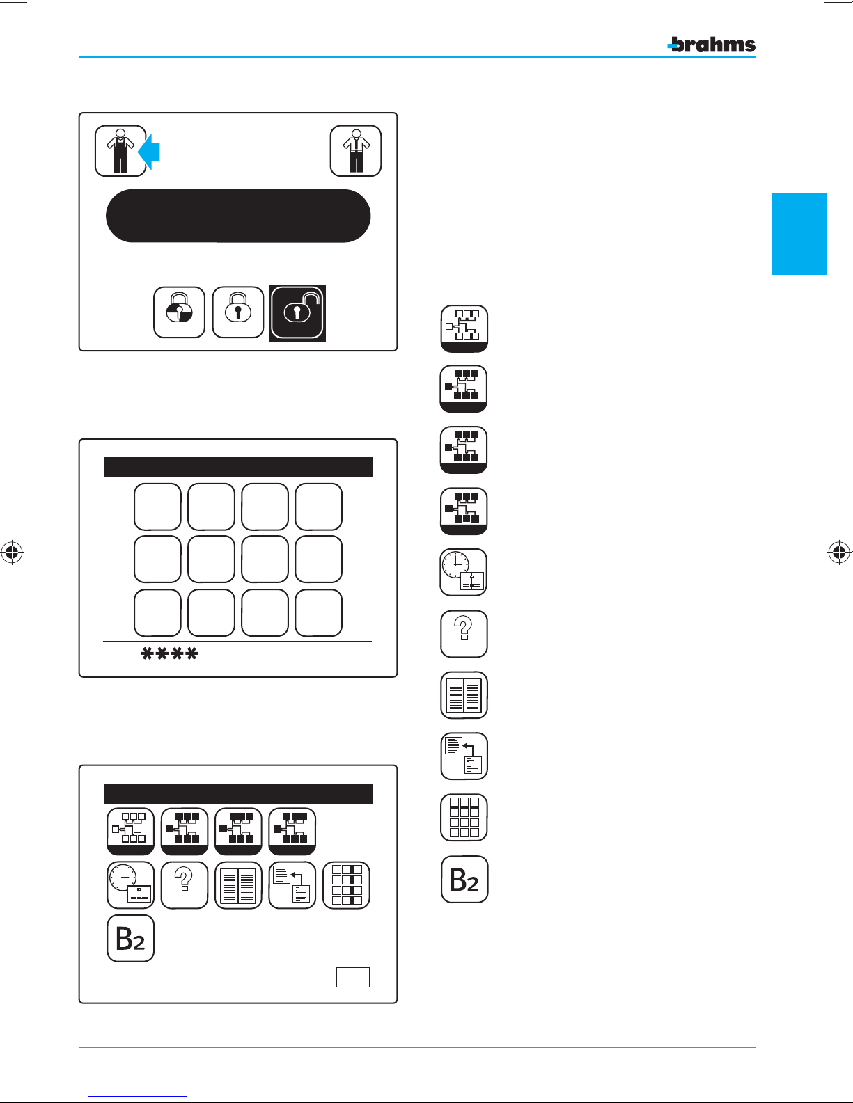
With the system turned o , i.e., with no area armed,
press the icon ( g. 1).
A keypad will appear on which to enter the Installer
Code
(which at the rst start-up will be 5, 6, 7, 8, g .
2) in order to access the
Installer Menu ( g. 3).
Fig. 1
12
Fri
Partial
:
03rd
Armed
30
March
Disarmed
Enter Code
2 1 3 4
6 5 7 8
Esc OK
9 0
The following pages will analyze all the items of the
“Installer Menu”, which are:
Learn
Learn
I I I
I
I I
I
S
S
S S S
View
P
P P
P
P
Setting
1
Identify
S
View
P
Setting
2
Date and Time
Identify
S
P
2
setting the control panel
Fig. 2
Fig. 3
Learn
1
Installer Menu
I I I
I
I I
I
Identify
2
TEST
S
MEM
S
S S S
View
TEST
MEM
P
S
S
ORY
P
P
Setting
P P
P
P
1 2 3
4 5 6
7 8 9
0
ESC
Test
ORY
Memory
Default Restore
1 2 3
4 5 6
7 8 9
0
Change Code
Control Panel Version
23
Page 24
2
Fig. 4
Devices Detected
Start
devices detection?
OK
ESC
Learn
Learning
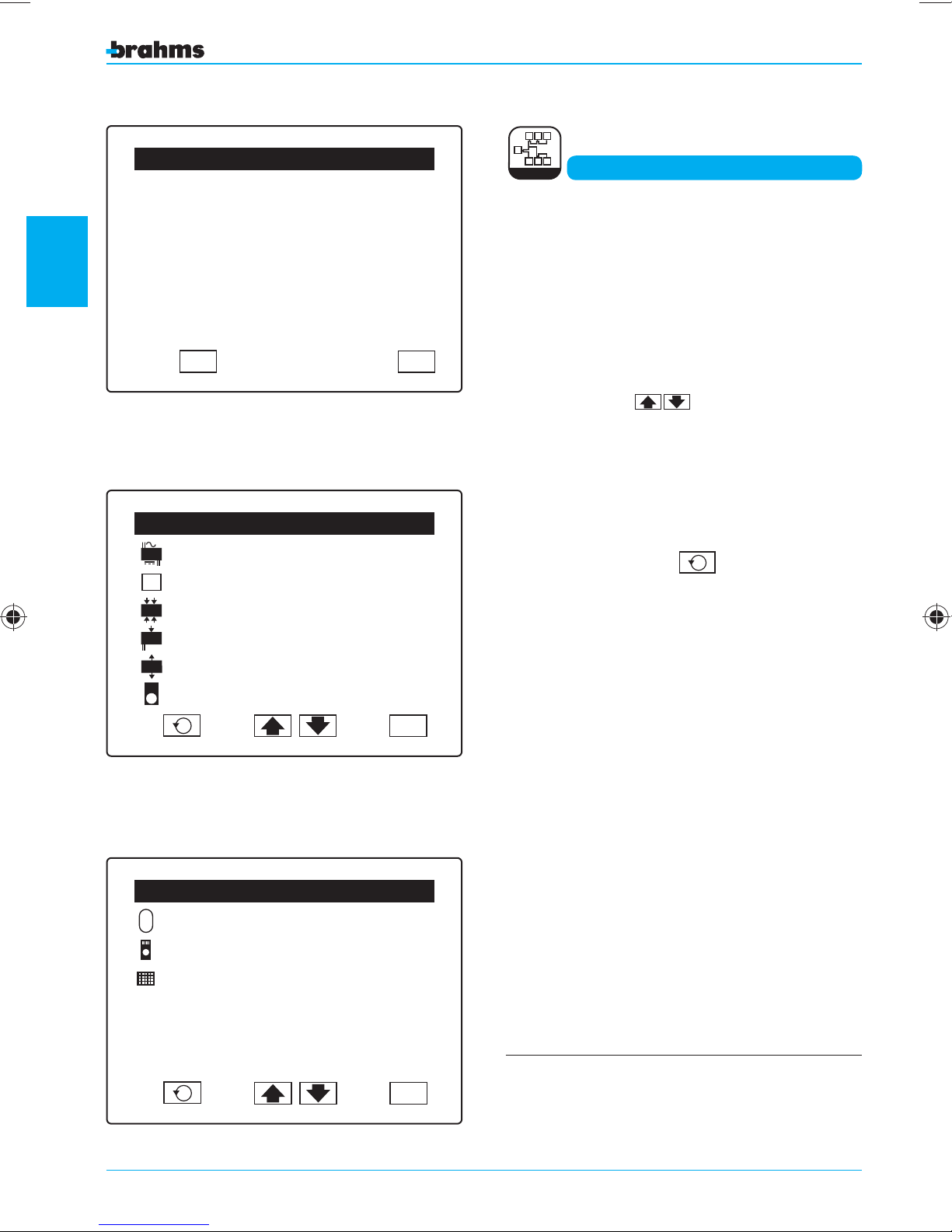
When the appropriate icon is pressed, the system
automatically detects the connected devices (fig.
4).
At this point, a list will appear with the number of
devices detected and a different icon for each type
of device (fig. 5, 6).
To scroll through the complete list of the devices,
press the buttons
.
If a device is not recognized, it may not have been
connected correctly.
POWER SUPPLIER
A
UC
CONTROL PANEL
4 IN MODULE
In
1 IN PW MODULE
Fig. 5
In
12V
2 OUT MODULE
Out
IR
WALL IR SENSOR
R
EXT. SIREN
IR RECEIVER
SUPPLEMENTARY KEYPAD
setting the control panel
Devices Detected
01
01
01
01
02
03
Devices Detected
01
03
03
ESC
Once the connection problems have been resolved,
the detection of the devices can be repeated by
simply pressing the icon
R
.
Pressing the icon ESC, we will now return to the
“Installer Menu” ( g. 3).
R
Fig. 6
24
ESC
Before proceeding with the commissioning,
it is important that all the devices are recognized by the system
Page 25
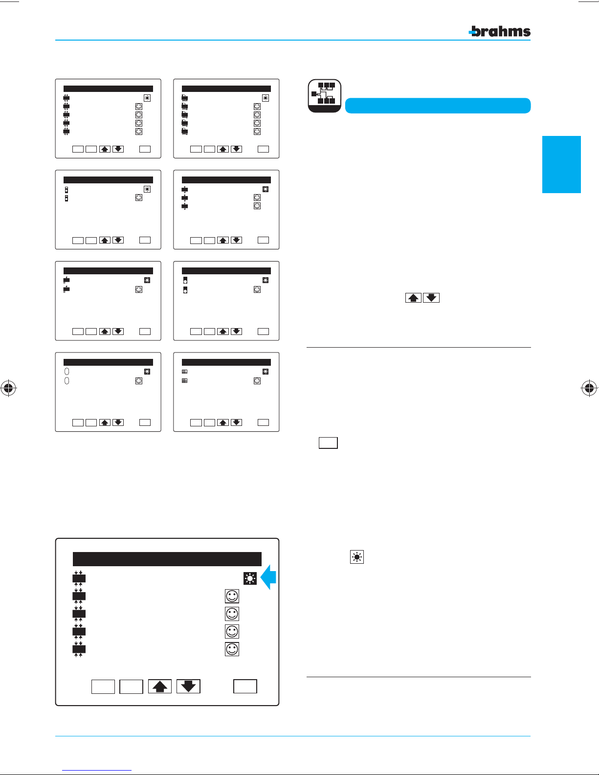
Devices Detection
In
4 IN Module
In
Mod 4 IN 01.1
In
Mod 4 IN 01.2
In
Mod 4 IN 01.3
In
Mod 4 IN 01.4
ID: 022228237 V:0.1
OK DEL
Devices Detection
IR Receiver
IR Receiver 01.1
ID: 022228233 V:0.1
OK DEL
Devices Detection
In
1 IN PW Module
12V
In
1 IN PW Mod 01.1
12V
01
01
01
ESC
ESC
Devices Detection
A
Power Supplier
A
PW. OUT 01.1
A
PW. OUT 01.2
A
PW. OUT 01.3
A
PW. OUT 01.4
ID: 02228296 V:0.1
OK DEL
Devices Detection
Out
2 OUT Module
Out
2 OUT Module 01.1
Out
2 OUT Module 01.2
ID: 022228259 V:0.1
OK DEL
Devices Detection
IR
Sensore IR Par.
IR
Wall IR 01.1
01
01
01
ESC
ESC
I I I
I
I I
I
Identify
Identification
By pressing the appropriate icon, we now proceed to
the identification of the devices. Using this function,
we can identify, name and set the components of
the burglar alarm system.
To facilitate the identification of each individual
device and its outputs or inputs, numbered progressively, these will now appear in a list divided
over several pages (fig. 7).
To scroll through the pages containing the list of
devices, use the icons .
2
ID: 022228382 V:0.1
OK DEL
Devices Detection
Ext. Siren
EXT Siren 01.1
ID: 022228226 V:0.1
OK DEL
Fig. 7
In
4 IN Module
In
4 IN Mod 01.1
In
4 IN Mod 01.2
In
4 IN Mod 01.3
In
4 IN Mod 01.4
ESC
01
ESC
ID: 022228632 V:0.1
OK DEL
Devices Detection
Rec. Keypad
REC Keypad 01.1
ID: 022228333 V:0.1
OK DEL
Devices Detection
01
01
ESC
ESC
In the event, once the siren has been recognized,
it is necessary to perform work on the installation
and on the wiring of the siren itself, (or branches
upstream from the siren), it is necessary to proceed
as follows in order to avoid the ’“Tamper Alarm”:
1- Erase the Siren(s) by pressing on the button
.
DEL
2- Carry out the necessary operations on the instal-
lation.
3- Perform the detection of the Siren(s) again and
recheck the setting.
DEVICES DETECTION
The icon
allows you to activate the LEDs and
buzzers present on the connected devices and
identify their position within the environment (fig.
8).
setting the control panel
ID: 022228776 V:0.1
OK DEL
Fig. 8
ESC
The firmware ID and version of each device is
displayed at the bottom of the screen.
25
Page 26
2
Devices Detection
In
4 IN Module
In
Mod 4 IN 01.1
In
Mod 4 IN 01.2
In
Mod 4 IN 01.3
In
Mod 4 IN 01.4
ID: 022228237 V:0.1
01
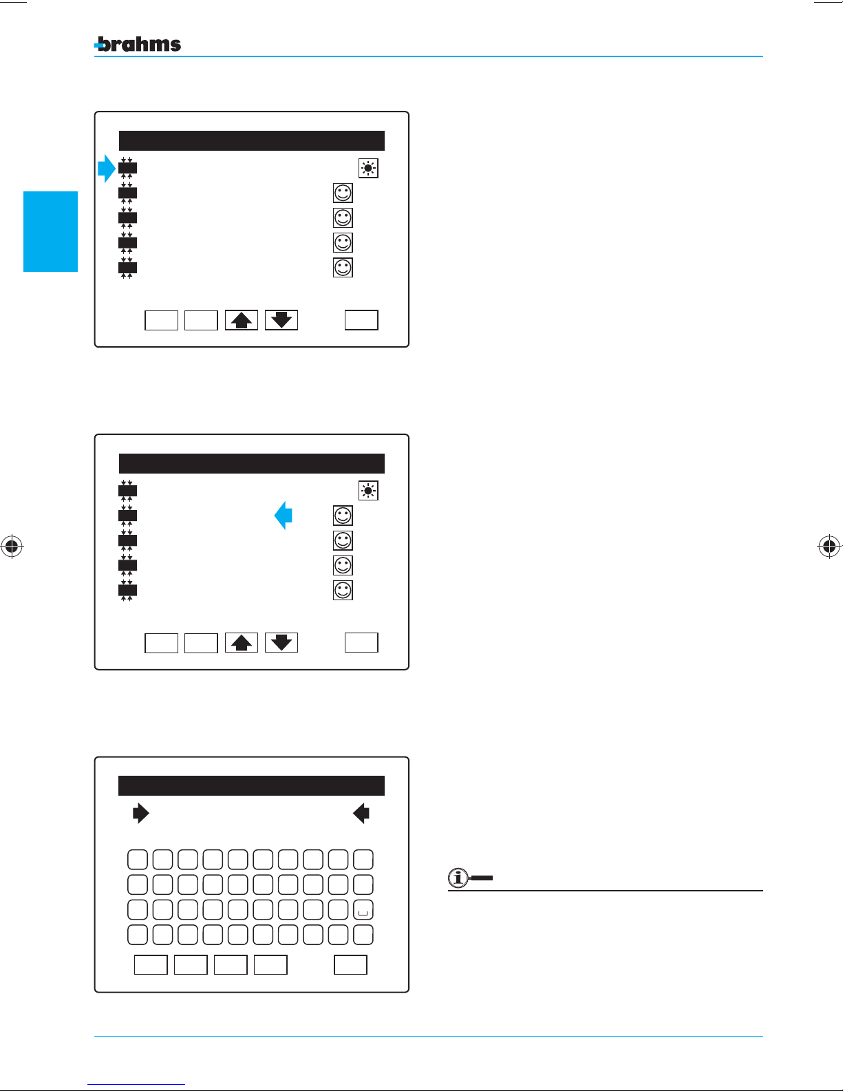
Consider a 4-input module as an example; the
first line (fig. 9) cannot be changed, it contains the
default name assigned by the system and represents
the type of device recognized.
Fig. 9
In
4 IN Module
In
Mod 4 IN 01.1
In
Mod 4 IN 01.2
setting the control panel
In
Mod 4 IN 01.3
In
Mod 4 IN 01.4
ID: 022228237 V:0.1
Fig. 10
OK DEL
Devices Detection
OK DEL
01
ESC
ESC
ASSIGNING A SYMBOLIC NAME TO THE
DEVICES
The next lines on the page (fig. 10) represent each
of the 4 inputs to which an external sensor can be
connected; pressing on the text, an alphanumeric
keypad will appear which allows us to assign them
a name.
We recommend that you use a symbolic name that
identifies their position, for example garage 01.1, or
that identifies their use, for example Gas detector
(fig. 11).
Press OK to con rm the selections made before
exiting from the screen with ESC.
Once these operations have been carried out for
all the connected devices, whether these are entry
panels, outputs, sirens, IR receivers or what have
you, we will have a precise picture of the location of
each component and/or its function.
Enter Zone Name
Garage 01.1
A B C D E F G H I J
K L M N O P Q R S T
U V W X Y Z ' . 0 1 2 3 4 5 6 7 8 9
CAP
Fig. 11
26
OK
DEL
BkSp
ESC
It is advisable that you carry out the identification operations carefully, as the names
assigned to the devices will help you to recognize them during the subsequent operations
as well.
Page 27
Devices Detection
IR
Sensore IR Par.
IR
Wall IR 01.1
ID: 022228632 V:0.1
OK DEL
01
ESC
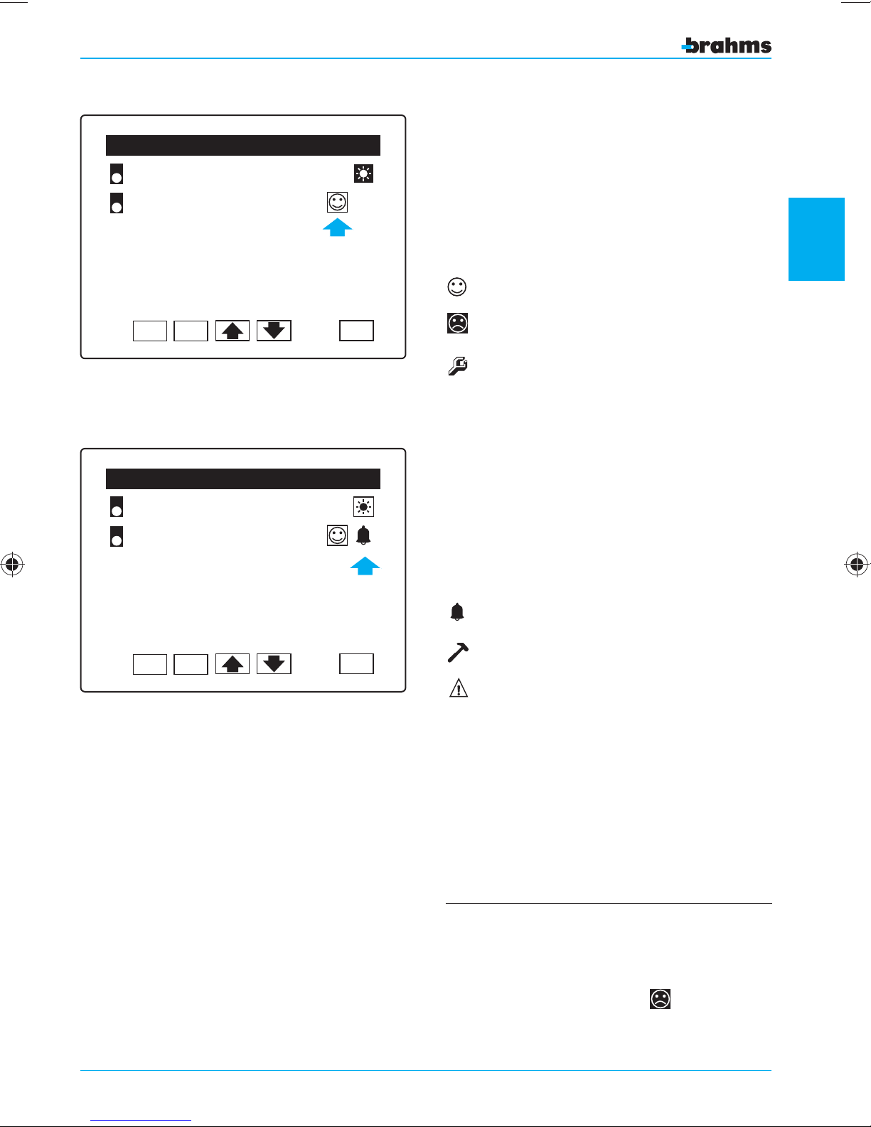
CHECK MODULE OPERATION
We will now consider as an example another device
recognized by the system during detection, and
we will analyze the column indicated by the arrow
(fig. 12).
Clicking on this icon, we act on the state of the
device as follows:
Included
Off
2
Fig. 12
Devices Detection
IR
Sensore IR Par.
IR
Wall IR 01.1
ID: 022228823 V:0.1
OK DEL
Fig. 13
In Test state
With the device in test state we can perform maintenance on the installation while keeping it active
but avoiding the e ective sounding of the alarm
sirens; the activation of the devices, however, will be
indicated in the “Event Log”.
01
The second column (fig. 13) cannot be changed
from the display, as it shows the effective state of
the connected device:
setting the control panel
in Alarm
Tamper
ESC
Fault
Press OK to con rm the selections made before
exiting from the screen with ESC.
- The state of the devices set by the installer (
in Test State) become a permanent state which
cannot be modified by the User.
- In order to avoid false alarms or malfunctioning, it
is recommended to turn Off
nected inputs
.
all the uncon-
On, Off,
27
Page 28
2
Fig. 14
setting the control panel
Devices Detection
In
4 IN Module
In
Mod 4 IN 01.1
In
Mod 4 IN 01.2
In
Mod 4 IN 01.3
In
Mod 4 IN 01.4
ID: 022228456 V:0.1
OK DEL
Devices Detection
IR
Sensore IR Par.
IR
Wall IR 01.1
01
01
ESC
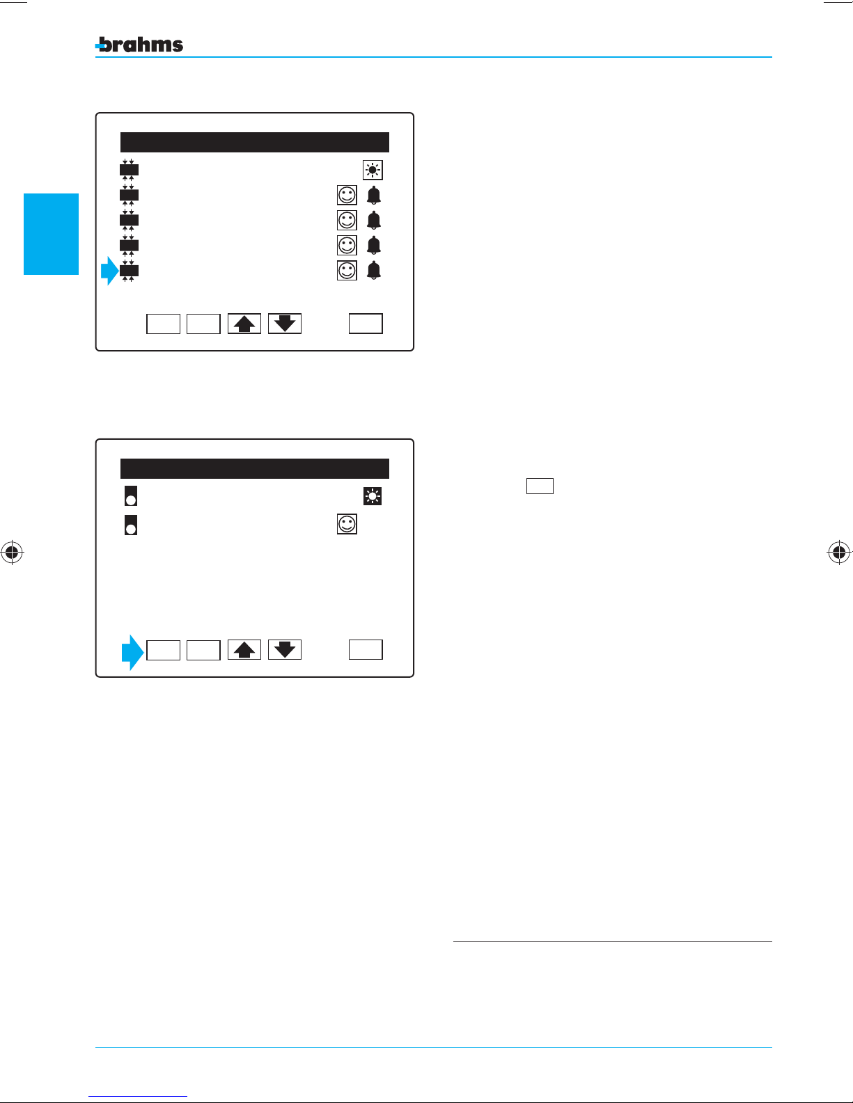
STATE OF THE CONNECTED SENSORS
If there are inputs in alarm even though there are
no activating events in progress, then it is necessary to check the correctness of the connection
and its consistency with the setting of the “type of
balancing” parameter for each input
this, just press on the icon of the device in alarm
( g. 14) to access all the setting functions which
will be discussed later in this manual in the “Setting
Menu” section.
ERASING A DEVICE
In the event you must remove a device, just press
the button
so that the device is no longer recognized by the
system.
(fig. 15) and con rm the selection
DEL
; in order to do
ID: 022228632 V:0.1
OK DEL
Fig. 15
ESC
For more information on the meaning of these
parameters, see the section entitled “General
Setting Information”.
28
Page 29
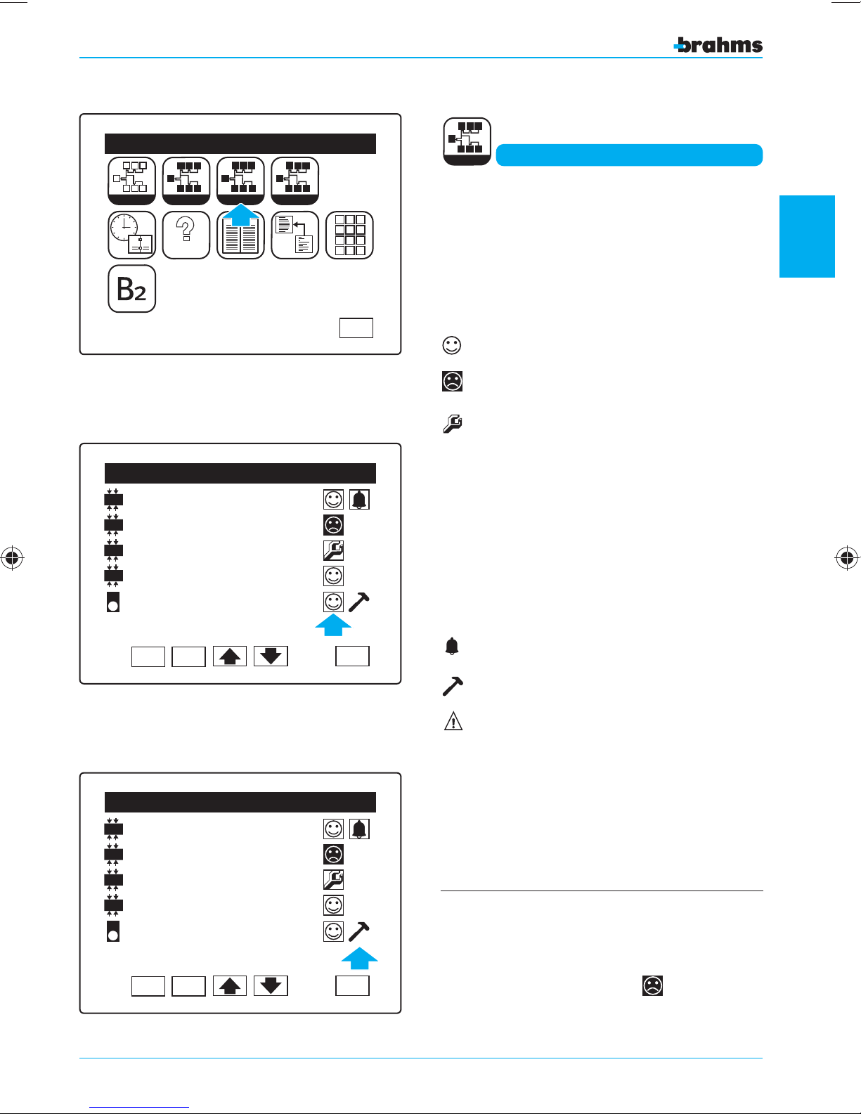
Fig. 16
Learn
1
Installer Menu
I I I
I
I I
I
Identify
2
TEST
S
MEM
S
S S S
View
S
S
S
S
S S S
S
ORY
P
P
Setting
P P
P
P
1 2 3
4 5 6
7 8 9
0
P
S
View
By pressing the appropriate icon (fig. 16), it is possible to check the state of the connected devices;
this state is represented by icons arranged in two
different columns. By clicking on the icons in the
View Devices State
2
first column (fig. 17), the state of the devices will
change as follows:
ESC
Included
Off
In Test state
Fig. 17
Fig. 18
View Devices State
In
Mod 4 IN 01.1
In
Mod 4 IN 01.2
In
Mod 4 IN 01.3
In
Mod 4 IN 01.4
IR
WALL IR SENSOR.01
OKDEL
View Devices State
In
Mod 4 IN 01.1
In
Mod 4 IN 01.2
In
Mod 4 IN 01.3
In
Mod 4 IN 01.4
IR
WALL IR SENSOR.01
OKDEL
ESC
ESC
With the device in test state, maintenance can
be performed on the installation while keeping it
active but avoiding the e ective sounding of the
alarm sirens; the activation of the devices, however,
will be indicated in the “Event Log”.
The second column (fig. 18) cannot be changed
from the display, as it shows the effective state of
the connected device:
in Alarm
Tamper
Fault
Press OK to con rm the selections made before
exiting from the screen with ESC.
- The state of the devices set by the installer (
On, Off,
in Test State) become a permanent state which
cannot be modified by the User.
- In order to avoid false alarms or malfunctioning, it
is recommended to turn Off
nected inputs
.
all the uncon-
setting the control panel
29
Page 30
2
Learn
1
Installer Menu
I I I
I
I I
I
Identify
2
TEST
S
View
MEM
S
S
S S S
ORY
P
P P
P
P
P
P
P
S
P
P
Setting
P P
P
P
1 2 3
4 5 6
7 8 9
0
Setting
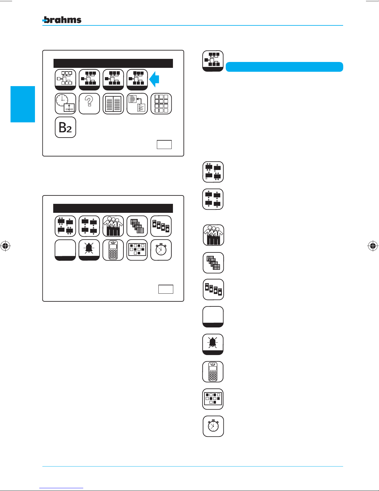
From the “Installer Menu”, pressing the appropriate
icon ( g. 19) will take us to the “Setting Menu”.
The definitions of the parameters for each burglar
Setting Menu
alarm input or zone is fundamental to the creation
of a safe, functional system.
Fig. 19
In
In
12V
In
In
12V
0 123456789
0 123456789
0 123456789
setting the control panel
0 123456789
Gen. Param.
Fig. 20
Setting Menu
Out
Out
Out
Out
Alarm
ESC
ESC
The icons present in the “Setting Menu” represent
the following (fig. 20):
In
In
12V
In
In
12V
Out
Out
0 123456789
0 123456789
0 123456789
0 123456789
Gen. Param.
Input Setting
Out
Out
Output Setting
User Setting
Keypad Setting
IR Receiver Setting
General Parameters
30
Alarm
Alarm Parameters
GSM Communicator
Sceneries Setting
Timer Setting
Page 31
Input Setting
4 IN Module 01.4
In
In
12V
In
12V
In
INPUT SETTING
01 Area
Burglar Alarm
Entry Delay=000
Exit Delay =000
NC contact
OK
Fig. 21
Enter Zone Name
Garage 01.1
A B C D E F G H I J
K L M N O P Q R S T
U V W X Y Z ' . -
ESC
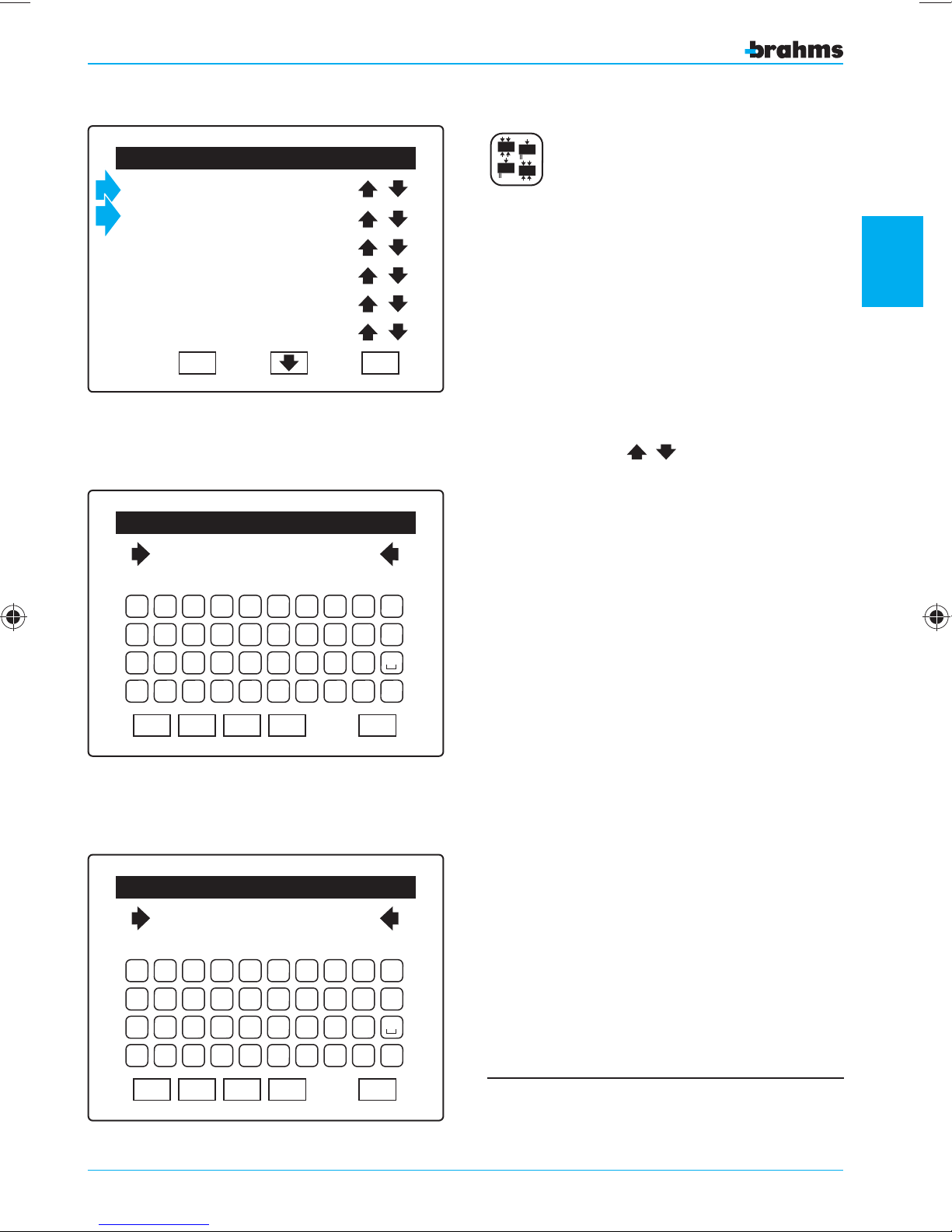
For greater immediacy in the viewing of events,
each input and each area can be assigned a description (14 alphanumeric characters for the inputs and
11 for the areas) (fig. 22). In order to do this, just
press on the name of the input or the area in question using the pen provided (fig. 21).
If the commissioning has been carried out properly,
you will read the name (which in any case can be
changed) already assigned during the identification of the devices.
Pressing the icons
will scroll through the
various inputs and areas available ( g. 21).
It is strategical and highly recommended that you
assign names to the inputs that identify their positions.
This rule also holds for the 10 areas available, for
which the system provides a non-modifiable numbering and a description that can be freely assigned
to the number (fig. 23).
2
setting the control panel
0 1 2 3 4 5 6 7 8 9
Fig. 22
CAP
OK
DEL
BkSp
Enter Area Name
01 Kitchen area
A B C D E F G H I J
K L M N O P Q R S T
U V W X Y Z ' . 0 1 2 3 4 5 6 7 8 9
Fig. 23
CAP
OK
DEL
BkSp
ESC
ESC
Press OK to con rm the selections made before
exiting from the screen with ESC.
The default setting establishes that:
Each input (zone) is assigned to the first Area.
31
Page 32
INPUT TYPES
2
Fig. 24
setting the control panel
Fig. 25
Input Setting
4 IN Module 01.4
01 Area
Burglar Alarm
Entry Delay=000
Exit Delay =000
NC contact
OK
Input Setting
4 IN Module 01.4
01 Area
Burglar Alarm
Entry Delay=000
Exit Delay =000
NC contact
OK
ESC
ESC
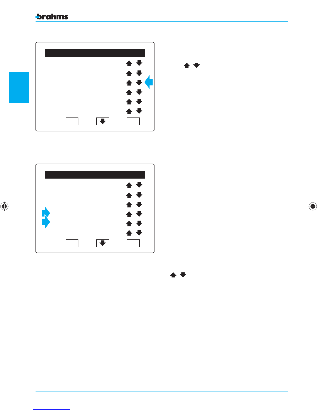
The input types can be selected by pressing the
icons
Burglar Alarm
Tamper Alarm
Silent Alarm
Panic Alarm
Rescue Alarm
Generic Alarm
Auxiliary Alarm from 1 to 8
Burglar Alarm
Pulse Arming Input
Level Arming Input
For each input de ned as a
Delay” and “Exit Delay” can also be de ned ( g. 25).
As the name suggests, the “Entry Delay” allows
the user time to enter the protected area and
deactivate the system by entering the proper code,
without activating the alarm system.
The “Exit Delay” allows the user time to exit the protected area after having entered the activation code.
During the time interval denominated as “Entry
Delay” or “Exit Delay”, the control panel and auxil-
iary keypads emit an intermittent buzzer sound to
advise the user of the imminent activation of the
alarm system.
The “Entry Delay” or “Exit Delay” can be adjust-
ed from 0 to 255 seconds by pressing the icons
( g. 24), and these can be:
“Burglar Alarm”, an “Entry
.
32
The “Entry Delay” and “Exit Delay” are active ONLY
for “Burglar Alarm” inputs.
When in standby, the system ignores signals from
inputs with an “Output Time” other than 0, which
therefore do not cause a “Not Ready” area or system signal. Upon activation o the system, they are
inserted at the end of the “Output Time” independently of their status. Therefore, these inputs cannot
be excluded with the “Forced Insertion” function or
with the “Automatic Insertion” function.
Page 33
Input Setting
Modulo 4 IN 01.4
Level Arming Input
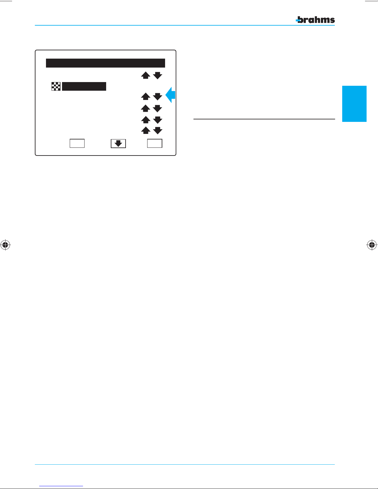
For the setting of inputs de ned as “Pulse Arming
Input” and “Level Arming Input”, the input setting
window will appear as shown in gure 26.
8 9 1071 2 3 4 5 6
This function allows you to arm/disarm the areas
selected using equipment outside the system.
Entry Delay = 000
Exit Delay = 000
NC contact
OK
Fig. 26
ESC
For more information on the meaning of these
parameters, see the section entitled “General
Setting Information”.
2
setting the control panel
33
Page 34
2
4 IN Module 01.4
01 Area
Burglar Alarm
Entry Delay=000
Exit Delay =000
NC contact
OK
Fig. 27
4 IN Module 01.4
Input Setting
Input Setting
ESC
TYPES OF BALANCING
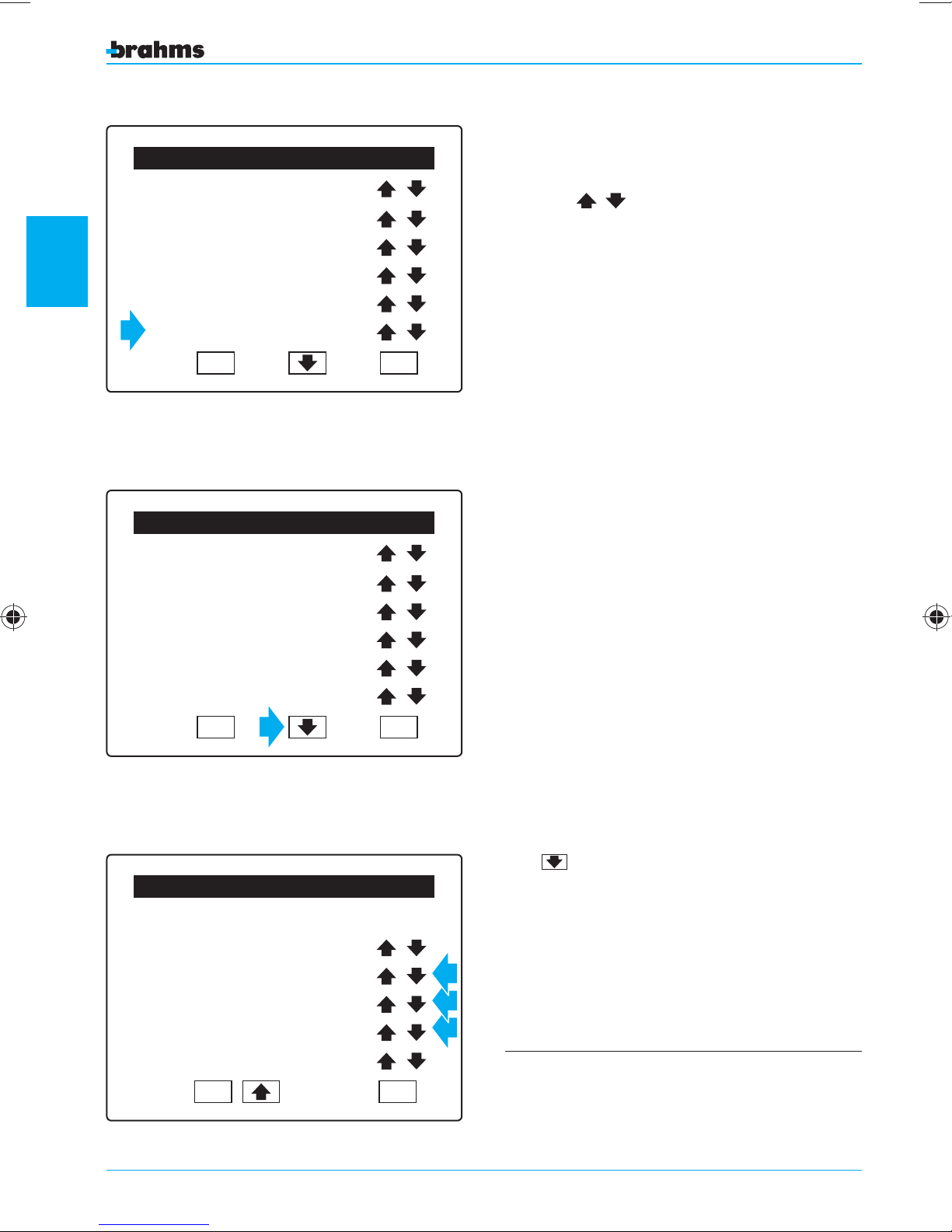
The types of balancing can be selected by pressing
the icons
able (fig. 27):
NC contact (Normally Closed)
NO contact (Normally Open)
One Resistance Mode
Two Resistance Mode
Vibration Sensor
Rolling Shutter Sensor
For the “Vibration Sensor” type of balancing, the
pulse length will also have to be specified.
- Pulse Length
minimum amplitude that the pulse coming from
the sensor must have in order to be considered as
an alarm.
and the following types are avail-
, the value that value determines the
01 Area
Burglar Alarm
setting the control panel
Entry Delay=000
Exit Delay =000
Vibration Sensor
Fig. 28
4 IN Module 01.4
Gong OFF
Pulse Lenght =000
Pulse Number =000
OK
Input Setting
ESC
For the “Rolling Shutter Sensor” type of balancing,
the following will also have to specified:
- Pulse Number, the value that determines the
number of the pulses that must be reached in
order to cause the alarm condition.
- Time Interval, the value that determines the dura-
tion of the time interval in which must be recorded
the set number of pulses in order to cause the
alarm condition (fig. 29).
In order to do this, it is necessary to access the next
page of the screen “Input Setting”, by pressing the
icon (fig. 28).
Time Interval =000
Tamper OFF
OK
Fig. 29
34
ESC
For more information on the meaning of these
parameters, see the section entitled “General
Setting Information”.
Page 35
Input Setting
4 IN Module 01.4
Gong OFF
Pulse Lenght =000
Pulse Number =000
Time Interval =000
Tamper OFF
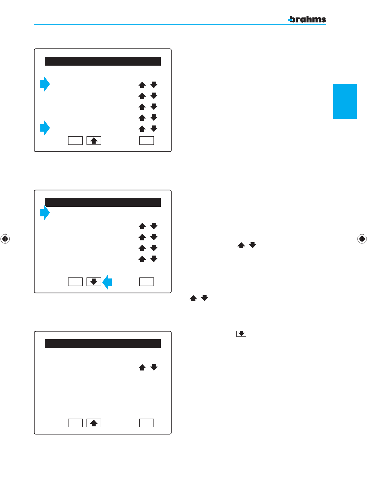
In this same window it is also possible to activate
or deactivate the “Tamper” and “Gong” options
( g. 30).
2
OK
Fig. 30
Input Setting
Wall IR01
01 Area
Burglar Alarm
Entry Delay =000
Exit Delay =000
Tamper OFF
OK
Fig. 31
ESC
ESC
IR SENSOR SETTING
The IR sensors can also be assigned an ID name just
like the inputs, and the sensors can be associated
with one of the available areas (which can also be
named as desired).
Using the arrows
of alarm to be associated with the sensor and the
Entry Delay and Exit Delay ( g. 31).
The “Entry Delay” or “Exit Delay” can be adjust-
ed from 0 to 255 seconds by pressing the icons
.
The “Entry Delay” and “Exit Delay” are active ONLY
for “Burglar Alarm” inputs.
, you can select the type
setting the control panel
Input Setting
Wall IR01
Gong OFF
Durata Impulso =000
Numero Impulsi =000
Durata Intervallo =000
Tamper OFF
OK
Fig. 32
ESC
pressing the icon
where you can activate or deactivate the “Gong”
option ( g. 32).
Press OK to con rm the selections made before
exiting from the screen with ESC.
takes you to the next screen
35
Page 36
2
Input Setting
Wall DT01
01 Area
Burglar Alarm
Entry Delay =000
Exit Delay =000
IR and MW Function
OK
ESC
DUAL-TECHNOLOGY SENSOR SETTING
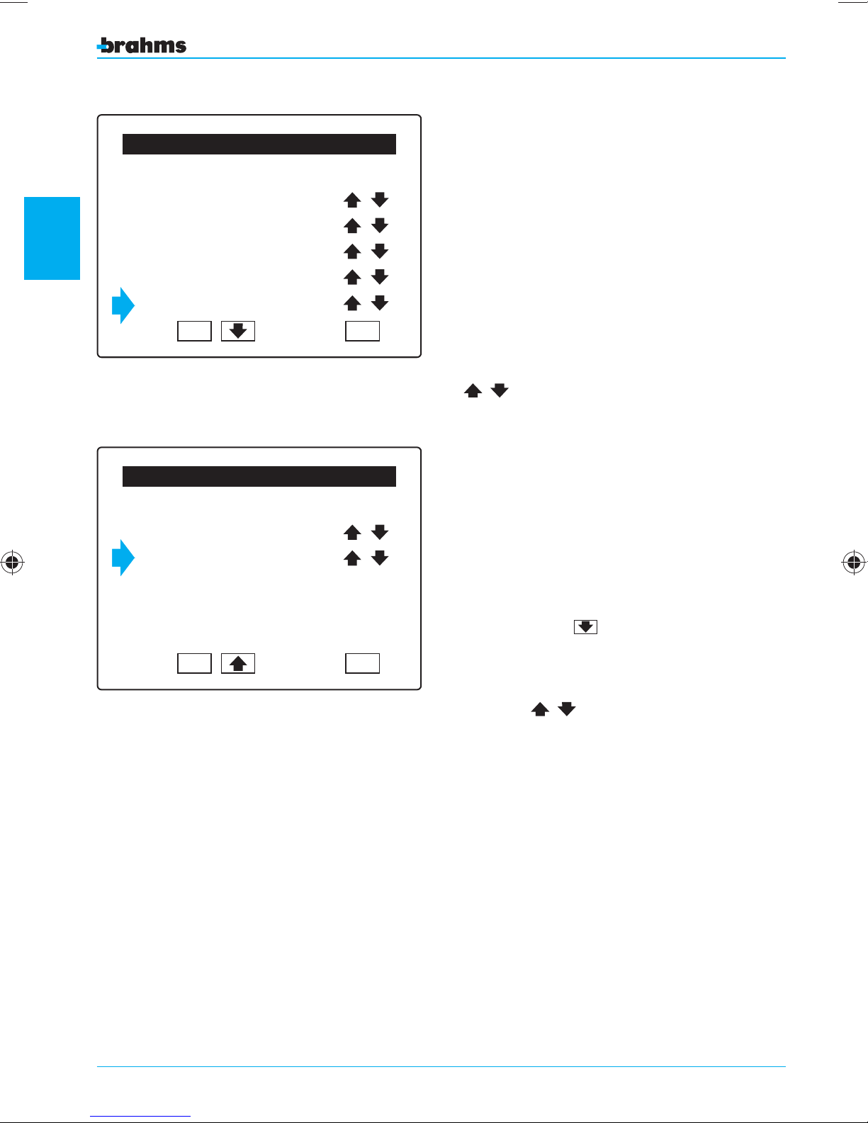
The dual-technology detector is able to detect the
presence of a burglar using two types of sensors:
An infrared sensor (IR), which detects the heat emanated from the person's body.
A microwave sensor (radar) (MW), which detects
motion.
Thus the setting window includes additional functions which are not present for a normal infrared
sensor.
Fig. 33
Wall DT01
Gong OFF
MW Sensibility = 05
setting the control panel
Fig. 34
Input Setting
OK
ESC
With the parameter “Function”, by pressing the icons
, you can select ( g. 33) the operating mode
for the detector:
IR or MW The alarm is activated even if only one of
the two sensors detects a presence.
IR and MW The alarm is activated only if both sen-
sors detect a presence.
MW The alarm is activated only by the
microwave sensor.
IR The alarm is activated only by the
infrared sensor.
Pressing the icon
where you can activate or deactivate the “Gong”
option ( g. 34).
With the parameter “MW Sensibility”, by pressing
the icons , you can adjust the detection
capability of the microwave sensor.
The values from 1 to 5 allow a proportional adjustment of the sensibility.
takes you to the next screen
36
1 = Minimum sensibility and minimum detection
distance.
5 = High sensibility and large detection distance.
0 = Adjustment off and maximum detection dis-
tance.
Press OK to con rm the selections made before
exiting from the screen with ESC.
Page 37
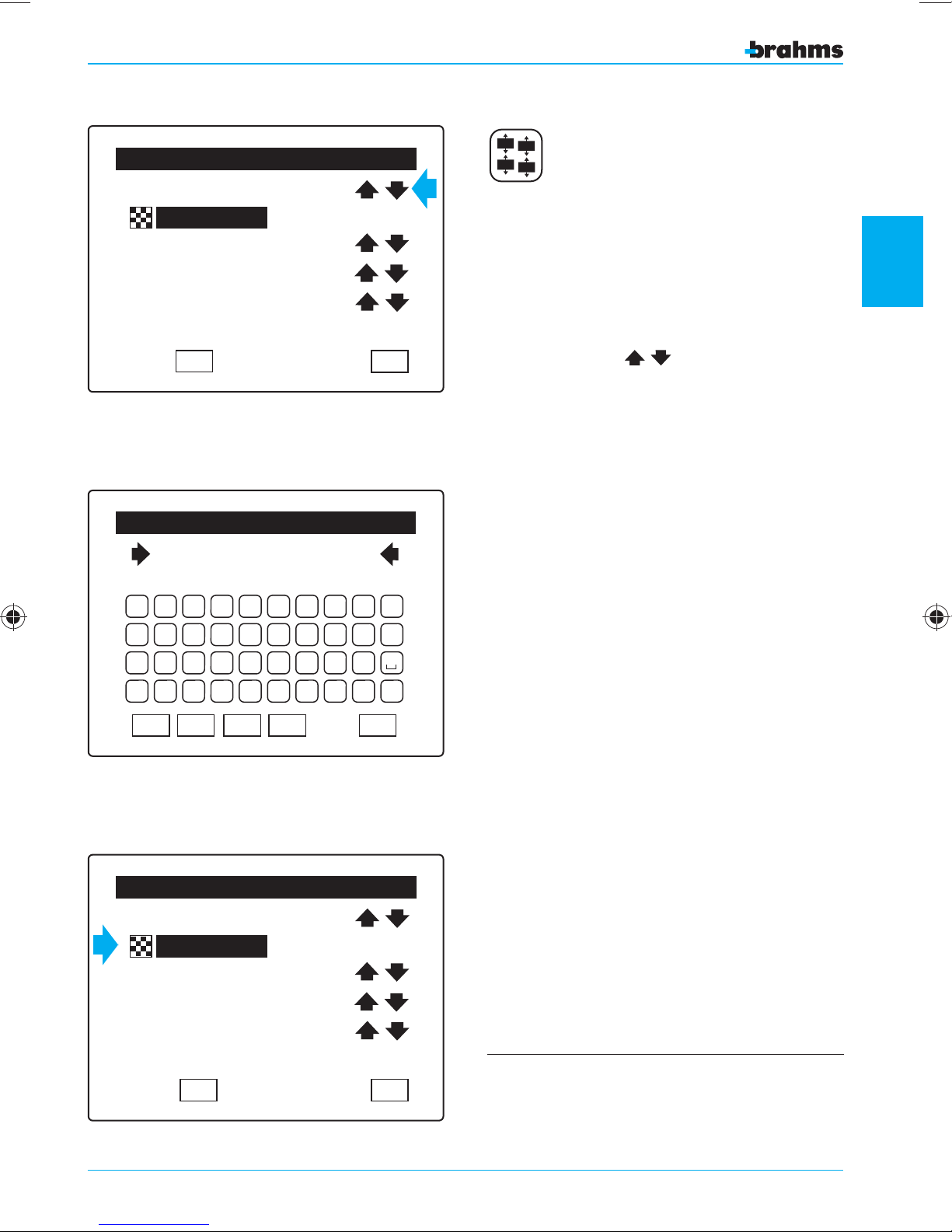
Output Setting
2 OUT Module
01.2
Areas Not Ready
Pulse 005
Normally Active
OK
Fig. 35
Enter Output Name
2 OUT Module
A B C D E F G H I J
K L M N O P Q R S T
U V W X Y Z ' . -
01.2
Out
Out
Out
Out
OUTPUT SETTING
8 9 10 7 1 2 3 4 5 6
By pressing on the appropriate button, we will
access the output setting section.
If the commissioning has been carried out properly,
on the first line of the window you will read the
2
name (which in any case can be changed) already
assigned during the identification of the devices.
ESC
Pressing the icons
, we can scroll through
the outputs available ( g. 35).
For greater immediacy in the viewing of events, each
output can be assigned an alphanumeric description
of 14 characters (fig. 36). To do this, just press on the
input or area in question.
The 4 outputs on the card of the power supplier or
those belonging to the 2-output expansion modules
can be activated by a series of events such as faults,
alarms and system states that can also be differentiated by the area of the system in which the event
setting the control panel
was generated.
0 1 2 3 4 5 6 7 8 9
Fig. 36
CAP
OK
DEL
BkSp
Output Setting
2 OUT Module
01.2
Generic Alarm
Level 000
Normally Disactive
OK
Fig. 37
If, for example, the areas 1-5 are selected (fig. 37),
ESC
then the output will be activated only if the event
has been triggered by an input belonging to the
areas 1-5.
8 9 10 7 1 2 3 4 5 6
For more information on the meaning of these
ESC
parameters, see the section entitled “General
Setting Information”.
37
Page 38
2
Output Setting
PW. OUT
01.4
Tamper Alarm
Level 000
Normally Disactive
OK
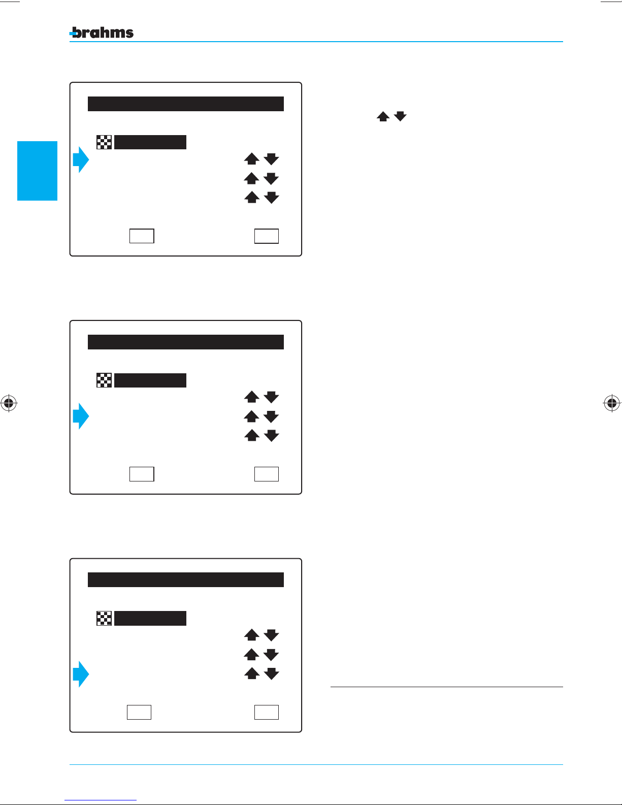
Not all events are affected by the "area of origin".
The available events can be selected by pressing
the icons ( g. 38).
8 9 10 7 1 2 3 4 5 6
ESC
The 4 outputs located on the power supplier are
provided with a standard setting that automatically
associates each output with an event:
PW OUT 01 Burglar Alarm
PW OUT 01.2 Tamper Alarm
PW OUT 01.3 Fault
PW OUT 01.4 Disarmed
Fig. 38
PW. OUT
Tamper Alarm
setting the control panel
Level 000
Normally Disactive
Fig. 39
Output Setting
01.4
OK
Output Setting
On the fourth line of the display, we can set (fig. 39)
the output type which can be either level or pulse.
Level
The output remains activated for the entire time the
triggering event is present.
Pulse
The output is activated by the presence of the event,
8 9 10 7 1 2 3 4 5 6
ESC
but remains active only for the set time.
On the next line of the display, we can set (fig. 40)
the type of activation associated with the output,
which has two options.
Normally Disactive
The output is normally inactive. It is activated
when an event is present.
Normally Active
The output is normally active. It is deactivated when
an event is present.
Press OK to con rm the selections made before
exiting from the screen with ESC.
PW. OUT
01.4
Burglar Alarm
Pulse 005
Normally Active
OK
Fig. 40
38
8 9 10 7 1 2 3 4 5 6
For more information on the meaning of these
ESC
parameters, see the section entitled “General
Setting Information”.
Page 39
User Setting
User 01
1 2 3 4
1 2 3 4 5 6 7 8 9 10
2
4
1 2 3 4
3
1
5 6 7 8 9 10
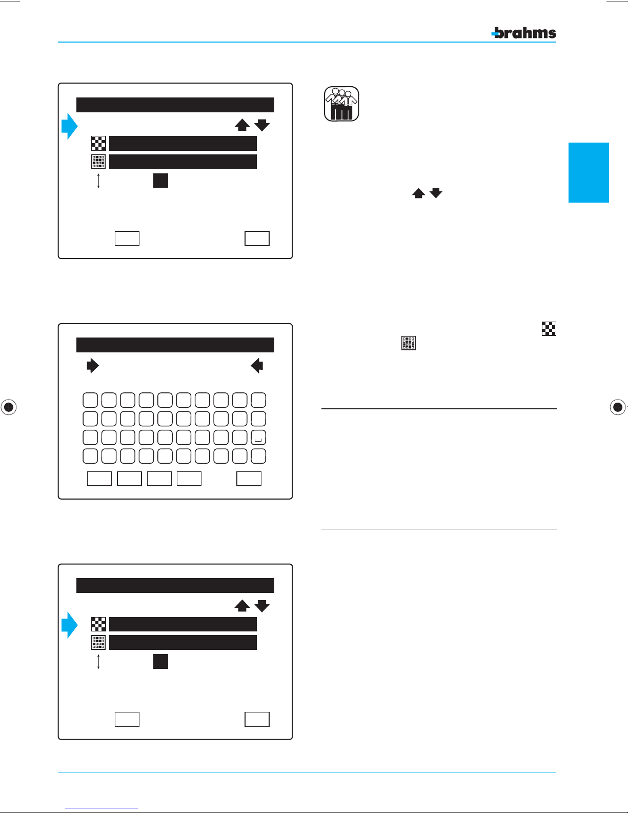
USER SETTING
By pressing on the appropriate button, we will
access the User parameter setting section.
Pressing the icons
, we can scroll through
the various users that can be set.
2
OK
Fig. 41
Enter User Name
Marco
A B C D E F G H I J
K L M N O P Q R S T
U V W X Y Z ' . 0 1 2 3 4 5 6 7 8 9
Fig. 42
CAP
OK
DEL
BkSp
ESC
ESC
For greater immediacy in the viewing of events, each
user can be assigned an alphanumeric description
of 14 characters for certain identification. To do this,
just press on the name of the User (fig. 41) and the
keypad will appear (fig. 42).
Each User can be assigned a group of areas
and/or sceneries that will be the only ones the
User can arm and/or disarm (fig. 43).
To prevent malfunctions, all areas involved in the
scenarios assigned to a user must in turn be assigned to the same user.
setting the control panel
User Setting
Marco
1 2 3 4
1 2 3 4 5 6 7 8 9 10
2
4
1 2 3 4
3
1
OK
Fig. 43
5 6 7 8 9 10
ESC
The default setting establishes that:
• All areas and all sceneries are assigned to all User
Codes;
• The highest Level of Priority (4) is assigned to all
User Codes (4)
• At the first start-up there is only one User Code,
which will be “1 2 3 4”
• The setting of the assigned areas, the assigned
sceneries and the level of priority for each User
is carried out inside the “Installer Menu”; the
assigning of the Keypad Codes and Key Codes for
each User is carried out inside the “User Menu” by
a User with Priority Level 4.
39
Page 40
2
User Setting
Marco
1 2 3 4
1 2 3 4 5 6 7 8 9 10
2
4
1 2 3 4
3
1
5 6 7 8 9 10
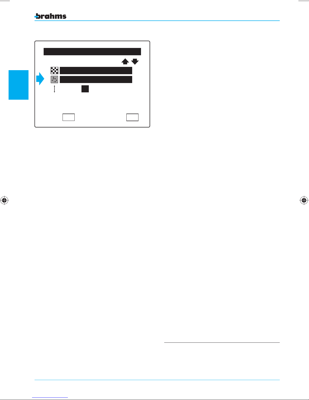
It is also possible to assign each user a priority level
from 1 to 4, which will allow or not the user to
perform a series of operations ( g. 44), as speci ed
in the tables on page 20.
Press
OK to con rm the selections made before
exiting from the screen with ESC.
Fig. 44
setting the control panel
OK
ESC
40
For more information on the meaning of these
parameters, see the section entitled “General
Setting Information”.
Page 41
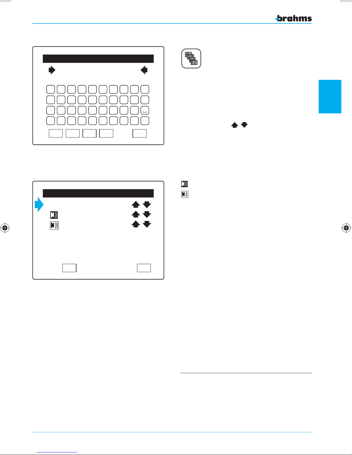
Enter Keypad Name
Kitchen Keypad
A B C D E F G H I J
K L M N O P Q R S T
U V W X Y Z ' . -
KEYPAD SETTING
Each auxiliary keypad can be assigned a symbolic
description for certain identification of the device.
To do this, just select the name of the device and
the alphanumeric keypad will appear (fig. 45).
2
0 1 2 3 4 5 6 7 8 9
Fig. 45
CAP
OK
DEL
BkSp
Keypad Setting
01 Keypad
E/E Delay
Alarm
OK
Fig. 46
ESC
ESC
Pressing the icons
the various keypads available ( g. 46).
For each keypad, you can set whether or not it
should emit a sound signal during the Entry Time
and Exit Time and during the Alarm Time (fig. 46).
Sound signal on
Sound signal off
Press OK to con rm the selections made before
exiting from the screen with ESC.
, we can scroll through
setting the control panel
The default setting establishes that:
• for the keypads, the sound signal is enabled during
the Entry and Exit Delay and during the Alarm Time;
• A maximum of 8 Keypads and 8 IR Receivers can be
connected on the bus line to the Control Panel;
41
Page 42
2
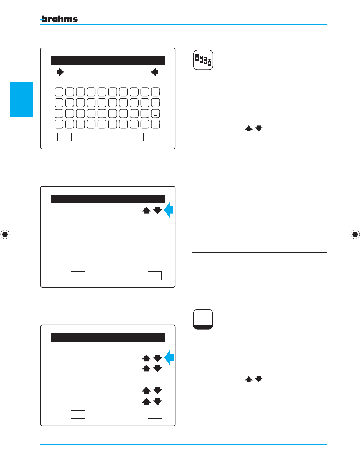
Enter Zone Name
Garage Receiver
A B C D E F G H I J
K L M N O P Q R S T
U V W X Y Z ' . -
IR RECEIVER SETTING
Each ir receiver can be assigned a symbolic description for certain identification of the device. To do
this, just select the name of the device and the
alphanumeric keypad will appear (fig. 47).
0 1 2 3 4 5 6 7 8 9
CAP
Fig. 47
Garage Receiver
setting the control panel
Fig. 48
BkSp
DEL
OK
IR Receiver Setting
OK
ESC
ESC
Pressing the icons
, we can scroll through
the receivers available ( g. 48).
Press OK to con rm the selections made before
exiting from the screen with ESC.
The default setting establishes that:
• A maximum of 8 Keypads and 8 IR Receivers can be
connected on the bus line to the Control Panel;
General Parameters
PW restore State
Previous
Supervision YES
GSM Control NO
Arming through Sceneries
Aut. Arming YES
OK
Fig. 49
42
ESC
0 123456789
0 123456789
0 123456789
0 123456789
Gen. Param.
GENERAL PARAMETERS
On the first line of this setting window, you can
decide how the control panel should behave when
the power supply returns after a power outage
(fig. 49).
Pressing the icons
, we can scroll through
the various options, which are:
Page 43

PW restore State
On
In the event both the battery and mains power supply fails for the control panel, the control panel will be
automatically set in the armed state when the power supply voltage is restored.
Off
In the event both the battery and mains power supply fails for the control panel, the control panel will be
automatically set in the disarmed state when the power supply voltage is restored.
Previous
In the event both the battery and mains power supply fails for the control panel, the control panel will be
automatically set in the previous state when the power supply voltage is restored.
Supervision
This parameter allows you to select whether or not the system can be managed by external supervision
systems (for example the BPT Mitho terminal, the YDRA supervision system, etc...).
GSM Control (can be changed by the User)
This parameter allows you to select whether or not the system can be remotely managed by means of a
GSM dialler (BXGM0001).
Arming through Areas/Sceneries
This parameter allows you to select if the partial activation of the system can occur through the activation
of areas chosen one at a time by the User (Arming through Areas) or through the activation of predefined
sceneries containing activation commands for groups of areas (Arming through Sceneries).
2
setting the control panel
Automatic Arming
When the function is active, if one or more inputs are in alarm during the arming of the system, these
will be temporarily excluded automatically and will return to being included only after the subsequent
disarming of the system.
When the function is not active, if there are any inputs in a state of alarm, the control panel will interrupt
the arming of the system and wait for the causes of the alarm to be eliminated (closing an open window,
for example). In any case, a priority level 3 or 4 user, bearing in mind the exception caused by inputs with
an output time other than 0 as described on page 32 of this manual, can however “force” the insertion
using the methods described in the “Forced Insertion” section of the B2UC0002 user manual.
Press OK to confirm the selections made before exiting from the screen with ESC and returning to the “Setting
Menu”.
43
Page 44
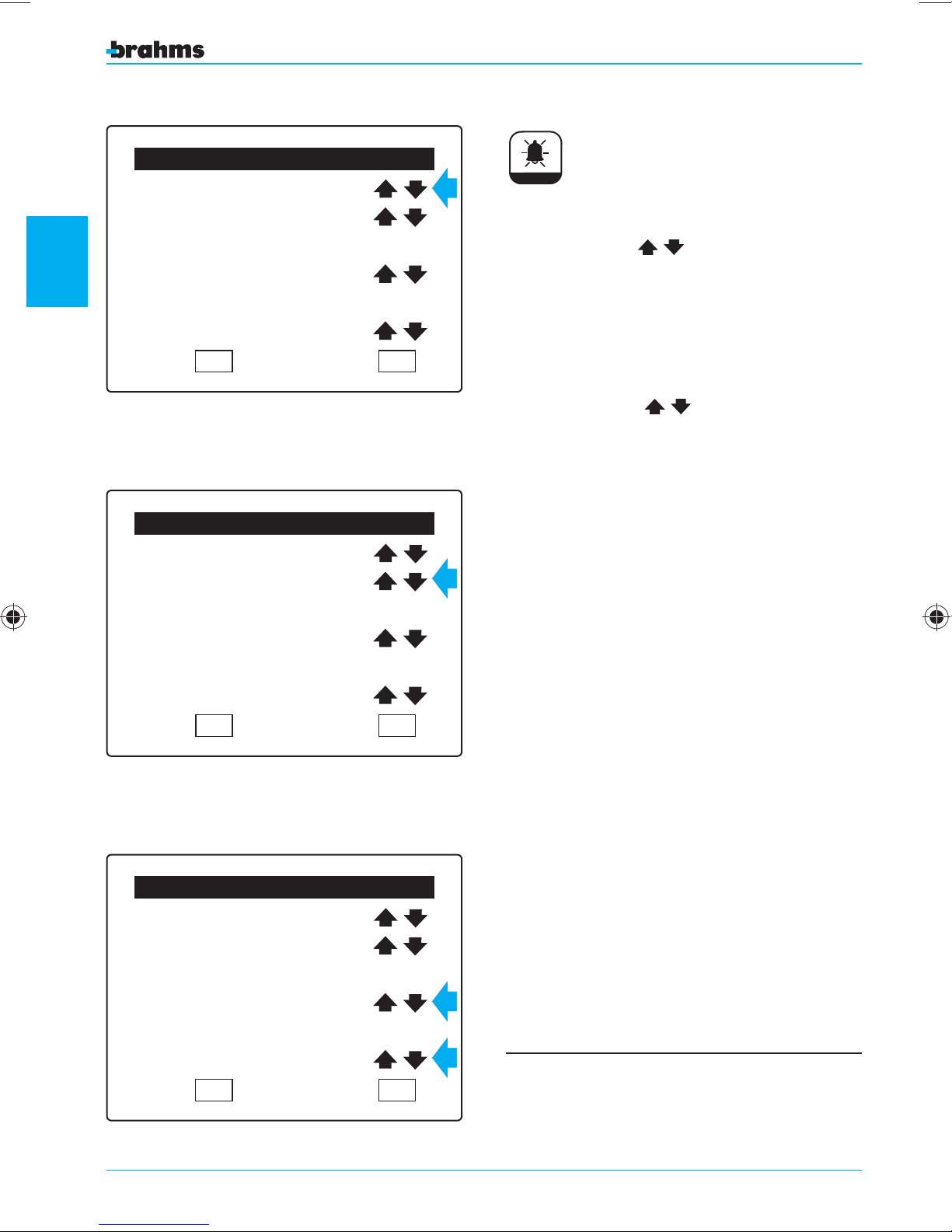
Alarm Parameters Setting
Alarm Time=600
Alarm
ALARM PARAMETERS
2
Fig. 50
setting the control panel
Fig. 51
Alarm Number=010
Burglar Alarm
Siren Enabled
Panic Alarm
Siren Disabled
OK ESC
Alarm Parameters Setting
Alarm Time=600
Alarm Number=010
Burglar Alarm
Siren Enabled
Panic Alarm
Siren Disabled
OK ESC
Alarm Time.
Pressing the icons
of the sounding of the siren for the “Burglar Alarm”,
“Panic Alarm” and “Tamper Alarm” events, in a
range from 0 to 600 seconds ( g. 50).
Alarm Number.
Pressing the icons
mum number of “Burglar Alarm”, “ Panic Alarm” and
“Tamper Alarm” events ( g. 51) that trigger the acti-
vation of the Sirens for each individual arming cycle
(maximum 20 times, 0= in nite number of times).
Burglar Alarm.
For this type of event it is possible to determine
whether or not the event triggers the activation of
the Sirens (fig. 52).
Panic Alarm.
For this type of event it is possible to determine
whether or not the event triggers the activation of
the Sirens (fig. 52).
Press OK to con rm the selections made before
exiting from the screen with ESC.
, we can set the duration
, we can set the maxi-
Alarm Parameters Setting
Alarm Time=600
Alarm Number=010
Burglar Alarm
Siren Enabled
Panic Alarm
Siren Disabled
OK ESC
Fig. 52
44
To fall under the parameters of the standard CEI 79-2,
the minimum duration of the alarm must be at least
180 seconds.
Page 45
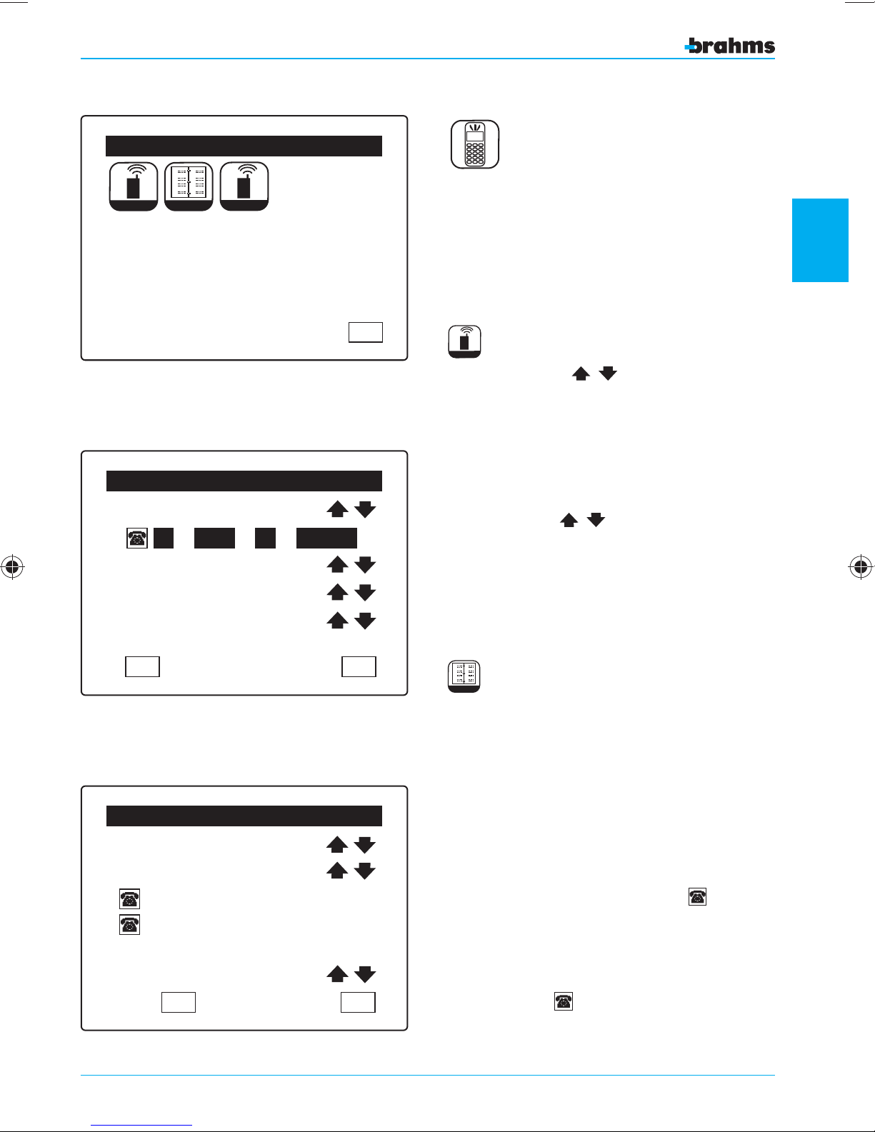
Fig. 53
GSM Communicator Menu
a
e
bf
c
g
h
d
Messaggi
Rubrica
Param. Gen.
GSM Message Setting
Burglar Alarm
8 9 1071 2 3 4 5 6
Vocal Messages YES
SMS No
Personal Message
= –
ESC
GSM COMMUNICATOR MENU
From the Setting Menu (fig. 20), press the appropriate button to access the “GSM Communicator
Menu” which allows you to set the main parameters
of the Brahms GSM communicator BXGM0001 (fig.
53).
Messages
GSM MESSAGE SETTING
Pressing the icons
next to the first item in
the window (fig. 54), we can scroll through the list of
events that generate a signal.
For each event you can select which numbers, from
the 10 possible numbers in the phone book, should
receive the warning message when the selected
event occurs.
Using the icons
located on the next two
lines, you can select the format in which the messages should be sent.
The “Personal Message function” is not active.
Press OK to con rm the selections made before
returning to the previous window with ESC.
2
setting the control panel
OK
Fig. 54
Phone Book Setting
Tel. Number = 01
Massimiliano
+3904225858585
032
SMS di conferma No
OK
Fig. 55
ESC
ESC
a
e
bf
c
g
h
d
Phone Book
PHONE BOOK SETTING
From the “GSM Communicator Menu” (fig. 48), select
the “Phone Book” icon to access the “Phone Book
Setting” window (fig. 55).
On the first line, you can select the position (1
through 10) in which to store the User's number in
the phone book.
The second line allows you to select which User and
relative phone number is to be associated with the
selected position.
At this point, press on the first icon to call up
the keypad with which to enter the phone number
(fig. 56).
If the phone number has more than 14 digits, you
will have to enter the extra digits after pressing on
the second icon .
45
Page 46
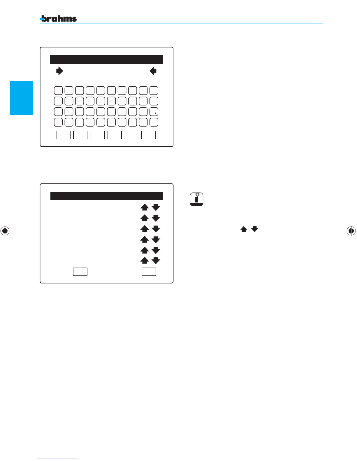
2
Fig. 56
setting the control panel
Fig. 57
Enter Phone Number
+393478
A B C D E F G H I J
K L M N O P Q R S T
BkSp
+
. -
ESC
U V W X Y Z
0 1 2 3 4 5 6 7 8 9
CAP
OK
DEL
Phone Parameters
Cyclic Sequence YES
Cycle Stop YES
ConfirmationTone YES
Attempts = 3
Pause = 255
Vocal Header NO
OK ESC
The telephone commands sent to the control panel
will be carried out only if the number from which
they are sent is present in the phone book. Furthermore, the User associated with the number must
enter his “User Code” and be assigned a “Level of
priority” that allows him to carry out the requested
action.
The last line in the “Phone Book Setting” window
(fig. 55) allows you to select if the phone book
number should receive SMS messages or not.
Press OK to con rm the selections made before
returning to the previous window with ESC.
The numbers MUST be preceded by the proper
international prefix (+39 for Italy).
Gen. Param.
PHONE PARAMETERS
The settings described below concern the voice
messages only.
Pressing the icons
list, you can set the following parameters ( g. 57):
Cyclic Sequence
“Cyclic Sequence YES” means that, if there is an
unanswered call, the communicator will not make
any other attempts but will go on to call the next
number in the phone book.
Cycle Stop
With “Cycle Stop YES”, the call cycle stops as soon as
one of the calls is successful.
Dial Tone
This allows to select whether or not there must be a
dial tone before dialling the number.
Attempts
“Attempts" means the number of unanswered calls
(from 1 to 20) after which the communicator dials
the next number in the phone book.
Pause
“Pause” means the time that must pass (from 0 to
255 seconds) between one call and the next.
The function “Vocal Header” is not active
next to the items in the
46246
Page 47
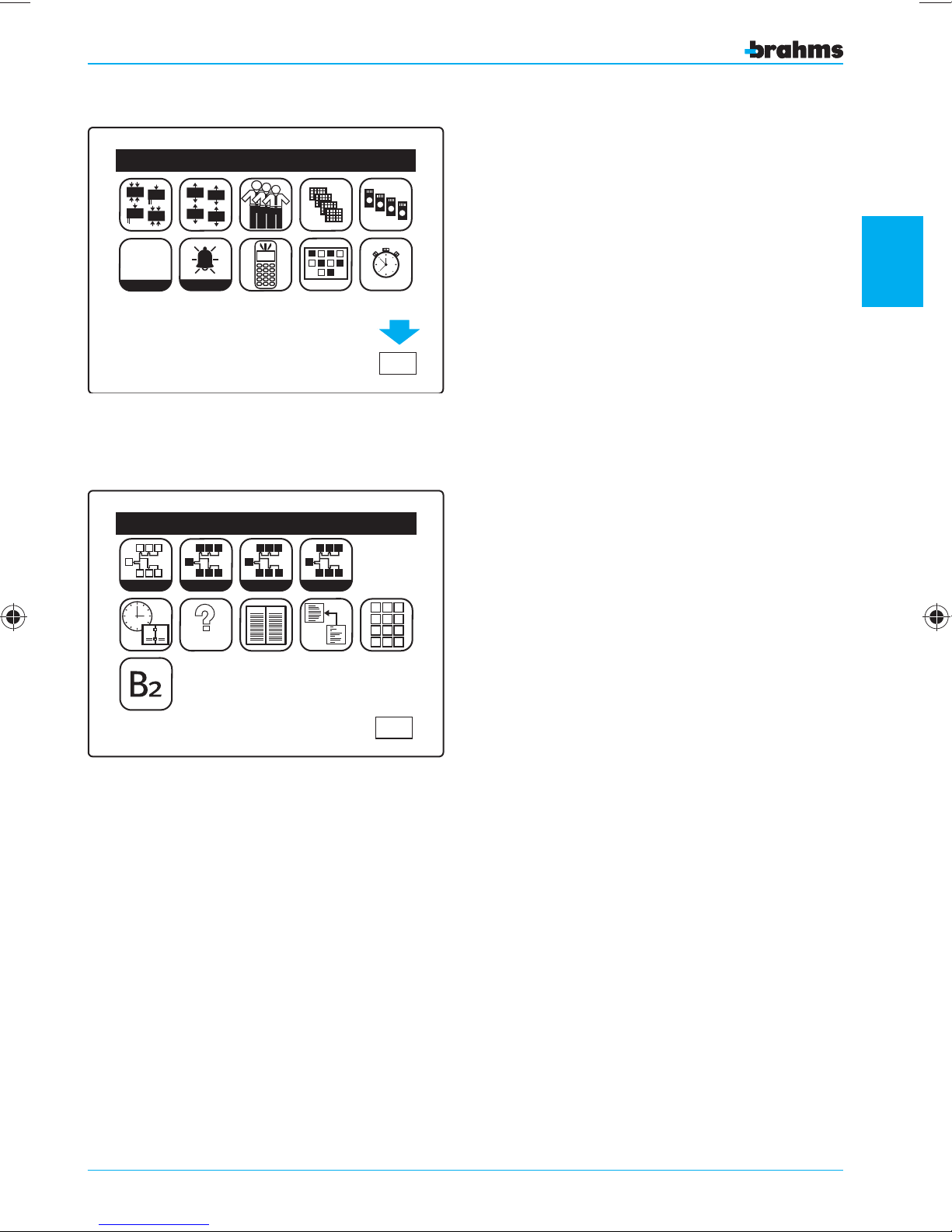
Setting Menu
Press OK to con rm the selections made before
returning to the previous window with ESC.
Fig. 58
In
In
12V
In
In
12V
0 123456789
0 123456789
0 123456789
0 123456789
Gen. Param.
Learn
1
2
Out
Out
Out
Out
Alarm
Installer Menu
S
S
I I I
I
I I
I
Identify
S
MEM
S
S S S
View
ORY
TEST
P
P
P
Setting
P P
P
2
ESC
P
1 2 3
4 5 6
7 8 9
0
setting the control panel
Fig. 59
ESC
47247
Page 48
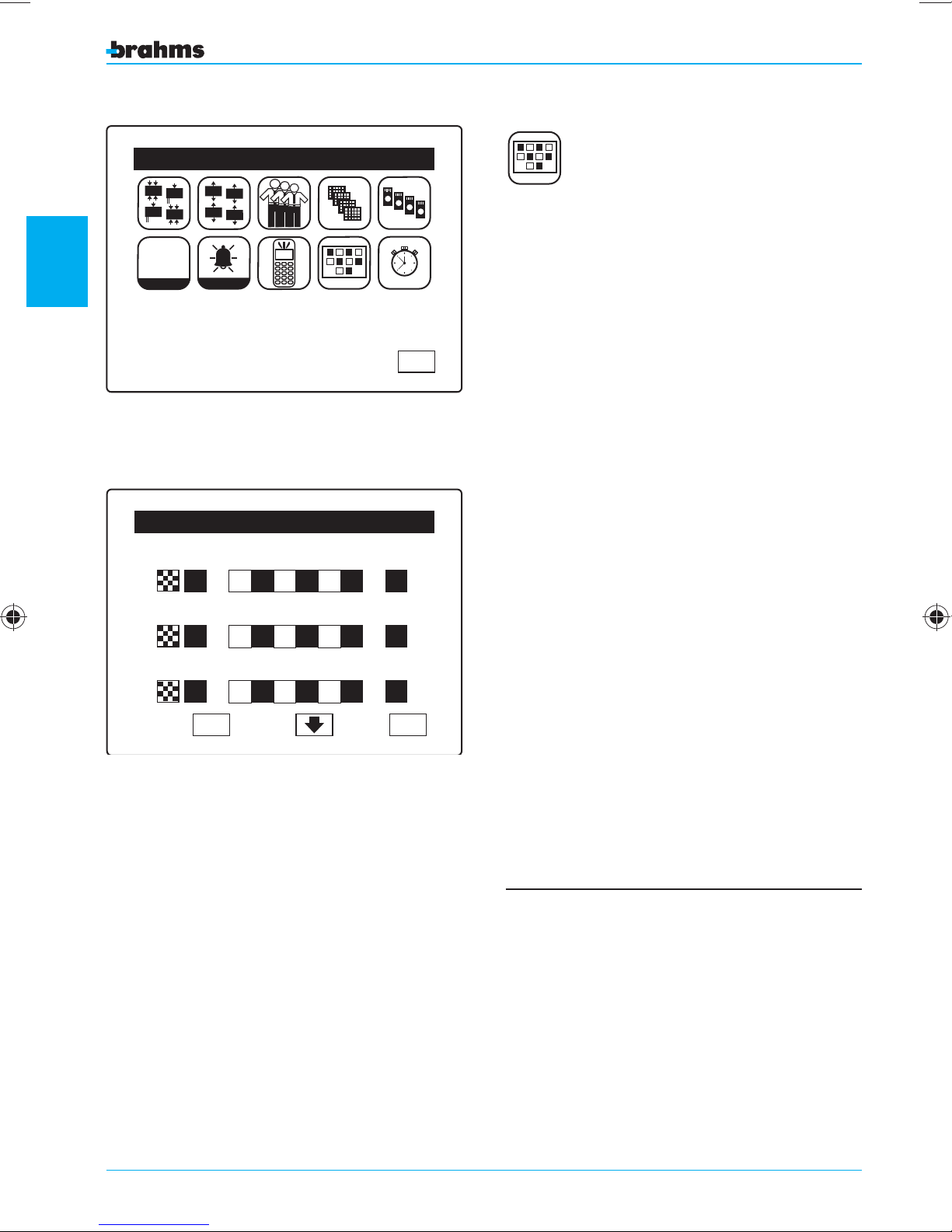
2
Fig. 60
setting the control panel
Fig. 61
Setting Menu
In
In
12V
0 123456789
0 123456789
0 123456789
0 123456789
Gen. Param.
In
12V
In
Out
Out
Alarm
Out
Out
Sceneries Setting
<Scenery Name 01>
1 X 3 4 5 6 7 8 X 10
<Scenery Name 02>
1 X 3 4 5 6 7 8 X 10
<Scenery Name 03>
1 X 3 4 5 6 7 8 X 10
OK
ESC
On
Off
Off
ESC
SCENERIES SETTING
From the “Installer Menu” (fig. 59), press the appropriate icon to access the “Setting Menu” and then
select the icon “Sceneries Setting”.
For each scenery, you can select a name (using the
normal procedures) and the arming state for all 10
areas.
Each area can be:
- Armed: area with white number on a black back-
ground;
- Disarmed: area with black number on a white
background in a square;
- Indi erent: “x”.
This last state means that, when the scenery is
armed, the area in question remains in the previous
state, i.e., its state is not changed.
As in the other menus, “clicking” on the centre of the
icon showing the area number will rotate through the
possible states.
Each scenery can also be activated (
On) or deac-
tivated (Off). Only the “activated” sceneries can
e ectively be used by the User for the Partial
Arming.
You MUST press “OK” to con rm the selection
made, otherwise the changes will be lost.
Press “ESC” to exit the window.
48
- To prevent malfunctions, all areas involved in
the scenarios assigned to a user must in turn be
assigned to the same user.
- By default, ALL THE SCENERIES ARM ALL THE
AREAS (graphically all the areas are initially shown
with a white number on a black background) i.e.,
THEY'RE THE SAME AS A FULL ARMING.
ALL THE SCENERIES ARE DEACTIVATED (O ).
The names of the sceneries are “Scenery 01”,
“Scenery 02”, …., “Scenery 09”, “Scenery 10”.
Page 49
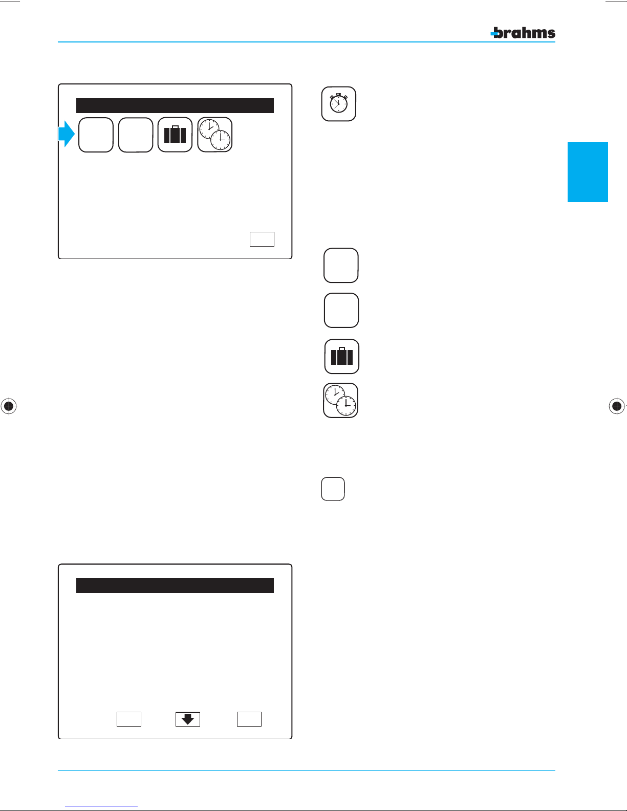
Fig. 62
1 09:00 On
2 12:15 Off
3 14:30 On
4 19:45 Off
5 23:00 Off
Timer Setting
MON PROG01
TUE PROG02
WED PROG03
SAT PROG04
SAN PROG05
ESC
TIMER SETTING
From the “Installer Menu” ( g. 59), press the appropriate icon to access the
“Setting Menu” and then
select the icon “Timer Setting”.
The icons in the “Timer Setting” menu represent the
following (fig. 62):
1 09:00 On
2 12:15 Off
3 14:30 On
4 19:45 Off
5 23:00 Off
MON PROG01
TUE PROG02
WED PROG03
SAT PROG04
SAN PROG05
Automatic Programs (20 steps)
Weekly Timer Setting (mon-sun)
Holydays Setting (32 days)
2
Automatic Programs List
Setting 01
Setting 02
Setting 03
Setting 04
Setting 05
Setting 06
OK ESC
On
On
Off
Off
Off
On
Daylight Saving Time Setting
1 09:00 On
2 12:15 Off
3 14:30 On
4 19:45 Off
5 23:00 Off
AUTOMATIC PROGRAMS
From the “Timer Setting” menu ( g. 62), press on the
appropriate icon to access the menu “Automatic
Programs list”.
Pressing the icon “Automatic Programs”, the
“Automatic Programs list” window appears which
contains the list of Programs. Clicking on the name
of the Program (which cannot be changed), we pass
to the window for setting the steps regarding the
selected Program.
Each Program can also be activated (On) or deactivated (O ).
Only the “activated” Programs can e ectively be
used. You MUST press “OK” to con rm the selection made, otherwise the changes will be lost. Press
“ESC” to exit the window.
setting the control panel
Fig. 63
49
Page 50
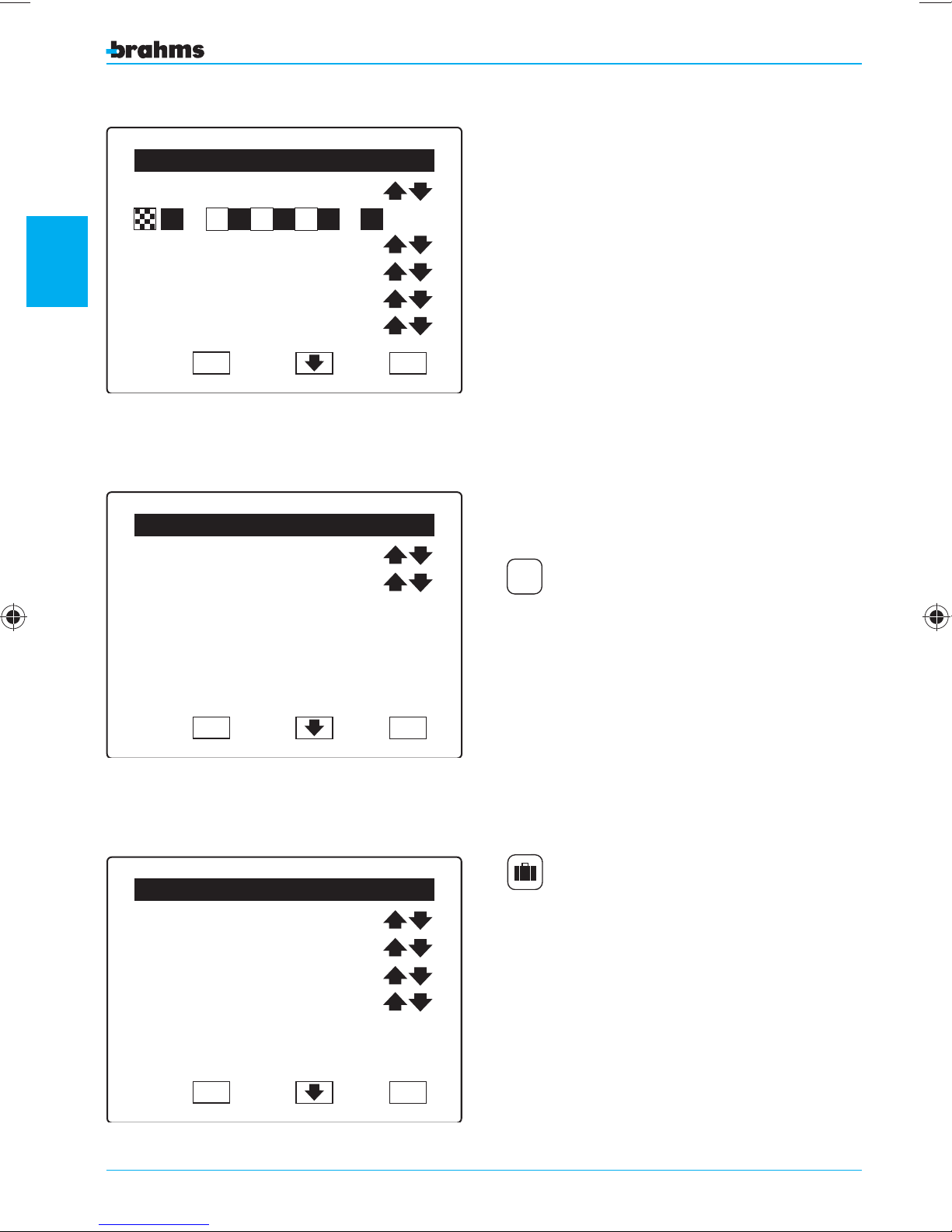
2
Automatic Programs Setting
01 Step 01
1 3 4 5 6 7 8 10
<Output Name>
Off
Hours 20
Minutes 30
OK
Fig. 64
Weekly Timer Setting
ESC
In the “Automatic Programs Setting” window, you
can set each of the 20 steps forming each Program.
For each step you can determine the arming state
of the areas (with the same procedures used for setting a scenery with 3 possible states for each area),
the output to be activated/deactivated and the time
(hour/minutes) at which the actions should be carried
out. The outputs that can be activated/deactivated
are ONLY those that have been con gured as "No
events" from the Output Setting menu. The option
“No Output” is also provided for the outputs.
On the rst line appears the number of the Automatic
Program being set and the step number being programmed; the arrows can be used to scroll through the
various steps of the Program.
You MUST press “OK” to con rm the selections made,
otherwise the changes will be lost. Press “ESC” to return
to the “Automatic Programs list” window.
Thursday
Program 01
setting the control panel
Fig. 65
<Holidays 01>
Day 31
Month 12
Program 01
Fig. 66
OK
Holydays Setting
OK
ESC
ESC
MON PROG01
TUE PROG02
WED PROG03
SAT PROG04
SAN PROG05
WEEKLY TIMER SETTING
From the “Timer Setting” menu ( g. 62), press
the appropriate icon to access the menu “Weekly
Timer Setting”.
This window allows you to associate one of the created Programs to each day of the week (from Monday
to Sunday). The option “None” is also provided in the
event no Program is to be associated with that day.
Each selection made should be con rmed with
“OK”, otherwise the changes will be lost.
Press “ESC” to exit the window.
HOLYDAYS SETTING
From the “Timer Setting” menu ( g. 62), press on
the appropriate icon to access the menu “Holydays
Setting”.
Each holiday (max 32) can be assigned a name
(using the normal procedures), a date within the
year (day and month) and one of the created
Programs. The option "None" is also provided.
Each selection made should be con rmed with
“OK”, otherwise the changes will be lost.
Press “ESC” to exit the window.
50
Page 51
Daylight Saving Time End
Day 31
Month 12
Hours 23
Minutes 59
OK
Fig. 67
Daylight Saving Time Start
Day 31
Month 12
Hours 23
Minutes 59
ESC
DAYLIGHT SAVING TIME SETTING
From the “Timer Setting” menu ( g. 62), press on
the appropriate icon to access the menu “Daylight
Saving Time Start” through which you can set the
day and time at which the system should pass from
solar time to daylight saving time and vice versa.
Each selection made should be con rmed with
“OK”, otherwise the changes will be lost.
Press “ESC” to exit the window.
2
setting the control panel
Fig. 68
OK
ESC
51
Page 52
Date & Time Setting
1
2
Date and Time
2
Fig. 69
setting the control panel
Hours
Date & Time Setting
Hours
OK
18 55
19 58
ESC
From the “Installer Menu”, pressing the appropriate
icon will take us to the window for the Date and
Time Setting.
Set the correct time by selecting the area to be
modified (fig. 69) and using the arrows on the side.
Proceed in the same manner to set the date after
having pressed the arrow at the bottom of the window (fig. 70) which allows access to the appropriate
screen (fig. 71).
Press OK to con rm the selections made before
exiting from the screen with ESC.
Fig. 70
Date
Month-Year
Fig. 71
OK
Date & Time Setting
Gio 17
Gen 08
OK
ESC
ESC
52
Page 53
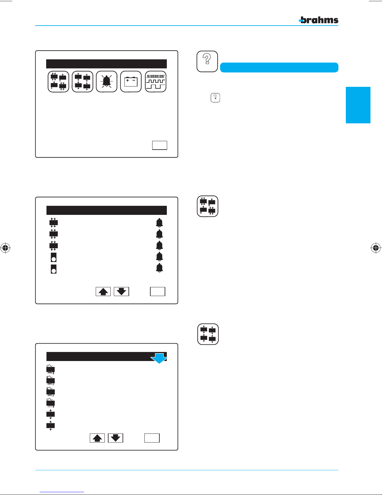
Fig. 72
Test Menu
In
In
12V
In
12V
In
Out
Out
Out
Out
Input Test
In
4 IN MOD 01.1
In
4 IN MOD 01.2
In
4 IN MOD 01.4
IR
WALL IR SENSOR 01
IR
WALL IR SENSOR 02
ESC
TEST
Device Test
From the “Installer Menu” ( g. 59), pressing the
icon
will take us to the “Test Menu” ( g. 72)
TEST
that allows us to test the correct operation of the
inputs, outputs, alarms and batteries of the connected devices.
Each individual test available is analyzed below.
In
In
12V
In
In
12V
INPUT TEST
Only the inputs that are in a state of alarm will
appear in this window (fig. 73).
Thus, by materially activating the inputs, we can
check their correct operation, name and location.
2
setting the control panel
Fig. 73
Out
Out
Fig. 74
Input Test
A
A
A
A
PW.
PW.
PW.
PW.
01/1
01/2
01/3
01/4
MOD. 2OUT 01/1
MOD. 2OUT
01/2
ESC
On
Off
On
Off
On
Off
ESC
Out
Out
Out
Out
OUTPUT TEST
All the connected outputs will appear in this window, with the icon in the right column ( g. 74) on
Off.
By pressing the pen provided on the icon Off, the
state of the output will change to On and the output will be activated in order to allow us to check
its operation.
When exiting from the window by pressing the icon
ESC, any outputs that may have been left active will
automatically be deactivated.
53
Page 54
Siren Test
EXT. SIREN 01
On
SIREN TEST
2
Fig. 75
setting the control panel
EXT. SIREN 02
Battery Test
A
PW.
EXT. SIREN
01
02
Off
ESC
The legend “ON” or “Off” next to the name of the
device acts as a switch (fig. 75).
By simply pressing on the legend we can turn the
sirens on or off.
BATTERY TEST
By simply pressing on the name of the device, we
will be informed about the state of the battery
housed inside the device (figg. 76).
Fig. 76
Fig. 77
Transmission Speed
IR
Bedroom Sensor 9
IR
Bathroom Sensor 8
IR
Kitchen Sensor 9
IR
Garage Sensor 8
OK
ESC
ESC
TRANSMISSION QUALITY TEST
Pressing the appropriate icon, a list of the inputs
will appear with a numerical value next to each that
indicates the speed and quality of communication
between the Control Panel and the device, on a
scale from 1 to 10 (fig. 77).
If the value is less than 7, check that the length of the
connection is within the limits indicated in the section
“General system information”.
54
Page 55
Fig. 78
Event Log
Mod 4 IN 03.4
Burglar
15/ 03/ 2006
EXT Siren 01
Tamper
14/ 03/ 2006
Door 03
Alarm
12/ 03/ 2006
Del Del
001
11:04
002
08:09
003
06:20
ESC
ORY
MEM
Event Log
The “Event Log” is structured so as to provide a
precise picture of the events concerning the system,
whether these are caused by burglar attempts,
tampering, alarms and faults or simply due to a user
arming or disarming the system.
Pressing the icons
the events and check their progression, indicated
by the number next to the name of the device that
generated the event. At the end of the list, the scrolling will start again from the beginning.
The most recent event that occurred is marked by
the number 001.
, we can scroll through
2
Fig. 79
Event Log
Bus PW
Fault
15/ 03/ 2006
Bus PW
Fault
15/ 03/ 2006
Del Del
Event Log
1 2 3
Mario
4 5 6
7 8 9
16/ 03/ 2006
0
1 2 3
Mario
4 5 6
7 8 9
15/ 04/ 2006
0
001
16:04
002
11:09
ESC
001
08:04
002
11:09
In the case of burglar, tamper or alarm events, for
example (fig. 78), next to the icon showing the
event, we can read the name of the input that generated the event and the date and time in which it
was activated.
setting the control panel
If the event is different from burglar, tamper or
generic alarms, it will be divided into two parts (fig.
79, 80).
The first part (with the icon in negative) reports the
date and time of the end of the event; the second
part (with the icon in positive) reports the date and
time of the start of the event.
Adele
14/ 04/ 2006
Del Del
Fig. 80
002
10:09
ESC
55
Page 56
2
Event Log
Mod 4 IN 03.4
Burglar
15/ 03/ 2006
EXT Siren 01
Tamper
14/ 03/ 2006
Door 03
Alarm
12/ 03/ 2006
001
11:04
002
08:09
003
06:20
During the commissioning and setting of the control panel, a large number of events will undoubtedly be registered. It is best to remove these before
handing the system over to the User.
The “Event Log” can be cancelled partially or completely using the icons
(fig. 81).
Del Del
Fig. 81
Event Log
Cancel all
previous events from:
Mod 4 IN 03.4
setting the control panel
Burglar
15/ 03/ 2006
included?
Fig. 82
ESC
By pressing the rst icon , you can cancel from
the log ( g. 82) the events chronologically previous
to the highlighted event ( g. 81).
001
11:04
ESC OK
Event Log
Cancel all
subsequent events from:
Mod 4 IN 03.4
Burglar
15/ 03/ 2006
included ?
Fig. 83
56
001
11:04
ESC OK
By pressing the second icon
from the log ( g. 83) the events chronologically
subsequent to the highlighted event ( g. 81).
OK to con rm the selections made before
Press
exiting from the screen with
, you can cancel
ESC.
Page 57
Default Restore Menu
P
P
P
Program
P P
P
1 2 3
4 5 6
7 8 9
P
0
Default Restore
This menu allows you to restore the system to the
(default) factory settings.
Fig. 84
Factory settings
Start
factory settings
restore?
OK
ESC
ESC
Pressing on the first icon (fig. 84) and confirming
the selection with
(fig. 85) will restore all the
OK
setting data to its original state at the time of the
first start-up.
Pressing on the second icon (fig. 84) and confirming
the selection with
(fig. 86) will restore the fac-
OK
tory-set code associated with the first user.
This function is quite useful in the event the user
loses his code.
Press OK to con rm the selections made before
exiting from the screen with ESC.
NOTE. Should it not be possible to access the
Restore Menu, in order to restore the factory settings, follow the procedure described on page 39
of the “Installation Manual”.
2
setting the control panel
Fig. 85
Factory settings
Start
first user
factory code
restore with “1234”?
OK
Fig. 86
ESC
57
Page 58
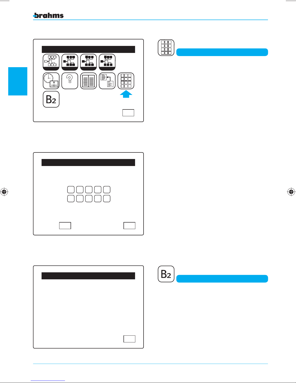
2
Installer Menu
S
S
View
MEM
S
S S S
ORY
Learn
1
2
I I I
I
I I
I
Identify
TEST
Fig. 87
Change Installer Code
Enter Install. User Code
1 2 3
4 5 6
7 8 9
P
S
P
P
Setting
P P
P
P
1 2 3
4 5 6
7 8 9
0
0
Pressing the appropriate button (fig. 87) will call up
a numerical keypad with which you can set a new
Installer Code (fig. 88).
Change Installer Code
Press OK to con rm the selections made before
exiting from the screen with ESC.
ESC
setting the control panel
Fig. 88
ID: 16777215
Ver.: 55.55
01
234
56789
012345
Code Not Valid
Control Panel Version
ESCOK
Control Panel Version
From the “Installer Menu” (fig. 87), pressing the button “B2” will display the Firmware ID and version
of the control panel (fig. 89); this information may
be particularly useful in case you need to contact a
service technician.
Fig. 89
58
ESC
Page 59
Table of the default settings of all the parameters
INPUTS
Parameter 4-Input Module Powered 1 Input Module Infrared Sensor
Description
Area
State
Input Type
Balancing Type
Exit Delay
Entry Delay
Tamper
OFF OFF OFF
Pulse Length
Pulse Number
Time Interval
Gong option
POWER SUPPLIER OUTPUTS
<Module Type xx> <Module Type xx> <Module Type xx>
Area 01 Area 01 Area 01
Included Included Included
Burglar Alarm Burglar Alarm Burglar Alarm
NC contact One Resistance Mode NC contact
000
000
004 004 004
002 002 002
010 010 010
NO NO NO
2
OUTPUT 1 OUTPUT 2 OUTPUT 3 OUTPUT 4
Description Alarm Tamper Fault Armed
Associated Areas ALL ALL ALL ALL
Activating Event Tamper Alarm Tamper Alarm Fault System Armed
Type 1 of the Output Pulse 004 Pulse 004 Pulse 004 Pulse 004
Type 2 of the Output Normally Disactive Normally Disactive Normally Disactive Normally Disactive
OUTPUTS USERS
Description Output xx
Associated Areas
Activating Event
Type 1 of the Output
Type 2 of the Output
Normally Disactive
All
No events
Pulse 004
KEYPADS
Description Keypad xx
Buzzer during T. Input/Output ON
Buzzer during T. Alarm ON
Description User xx
Associated Areas All
Priority Level 4
Keypad Code 1234 for User1
Key Code –
ALARM PARAMETERS
Alarm Time 40 seconds
Alarm Number 10
Siren Active for Burglar Alarm YES
Siren Active for Panic Alarm YES
setting the control panel
GENERAL PARAMETERS
When the power supply is restored, the control panel returns to the settings it had before the event.
59
Page 60
Tables of the default setting values
DEFAULT VALUES FOR EACH PROGRAM
Program Name Program State
Program 01 Off
Program 02 Off
Program 03 Off
Program 09 Off
2
Program 10 Off
DEFAULT VALUES FOR EACH PROGRAM STEP
STEP NAME AREA STATE
12345678910
Step 01 X X X X X X X X X X None Activated 00 00
Step 02 X X X X X X X X X X None Activated 00 00
Step 03 X X X X X X X X X X None Activated 00 00
Step 19 X X X X X X X X X X None Activated 00 00
Step 20 X X X X X X X X X X None 00 00
“X” indifferent
Default values for the Weekly Timer Setting
setting the control panel
Day Associated Program
Monday
Tuesday
Wednesday
Thursday
Friday
Saturday
Sunday
Default values for the Holidays Setting
Number Holiday name Day Month Associated program
01
02
03
31
32
Holiday 01
Holiday 02
Holiday 03
Holiday 31
Holiday 32
None
None
None
None
None
None
None
01 01
01 01
01 01
01 01
01 01
OUTPUT OUTPUT
STATE
HOUR MINUTES
None
None
None
None
None
Default values for Daylight Saving Time Start/End
Number Holiday name Day Month Associated program
01
02
60
Holiday 01
Holiday 02
01 01
01 01
None
None
Page 61

2
setting the control panel
61
Page 62

Page 63

Page 64

BPT Spa
Centro direzionale e Sede legale
Via Cornia, 1/b
33079 Sesto al Reghena (PN) - Italia
http://www.bpt.it - mailto: [email protected]
 Loading...