

Page 1
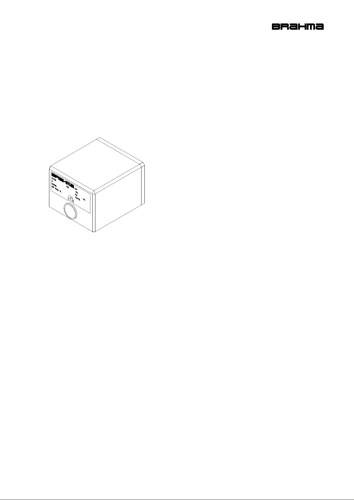
MF2 CONTROL BOX
CONTROL BOX FOR FORCED DRAUGHT
BURNERS FOR GAS AND OIL FUEL
DESCRIPTION
The MF2 control box is suitable for draught burners for gas
and oil fuel, for civil and industrial applications, with two
flame levels. This control can alternatively employ as
detection flame sensor both a probe, which makes use of
the rectification property of the flame (ionization), and a UV
phototube.
According to TÜV Bayern, Monaco, the control is in
compliance with the German regulation DIN 4788, part 3 ,
for power up to 350KW. It also obtained the DIN-DVGW
89.09fBN approval, now expired and not renewable.
The “Laboratorio di Macchine e Termotecnica del Centro
Studi ed Esperienze” in Rome - Capannelle tested the MF2
control for power up to 2332KW, which obtained the
certification n° 3704/187/77/21 and the approval of the
Ministry of the Interior for fire prevention (circulars n°68 and
n°42).
TECHNICAL DATA:
Supply voltage: 220V (-15%+10%)
50Hz (±5%)
on request: 110V
Operating temperature range: -10°C +60°C
Protection degree: IP40
Starting power consumption: 9 VA
Operating power consumption: 3,5 VA
Contact rating I max
- burner motor: 4 A
- valves (EV1, EV2): 2 A
- ignition transformer: 2 A
- alarm: 1 A
- regulators (T, PA, PG): 6 A
Times:
- prepurge time (TV): 30 s
- safety time (TS): 3 s
- drop out time on running flame failure: <1 s
- delay between EV1 - EV2: 30 s
- postpurge time: 5 s
Flame control
- minimum ionization current: 0,5 µA
- recommended ionization current: 7 µA
- minimum insulation resistance of cable and
flame detector device to earth: > 50 MΩ
- voltage on the detection probe: 350 V
- recommended operating voltage with phototube: >15µ A
Weight including socket: 600 g
CONSTRUCTION
The components of the control are fixed on a frame made
of pressed thermohardening material, with high dielectric
resistance. The enclosure protects the control from
mechanical damages, dust and dirt coming from the
outside during the installation.
Flexible unipolar conductors of different sizes connect the
components of the control, except for the flame detection
and prepurge control circuit, which is mounted on a printed
circuit.
4015_r00 1/4
Page 2
OVERALL DIMENSIONS
98.3 with socket NE
M4 fixing screws
9 with socket E
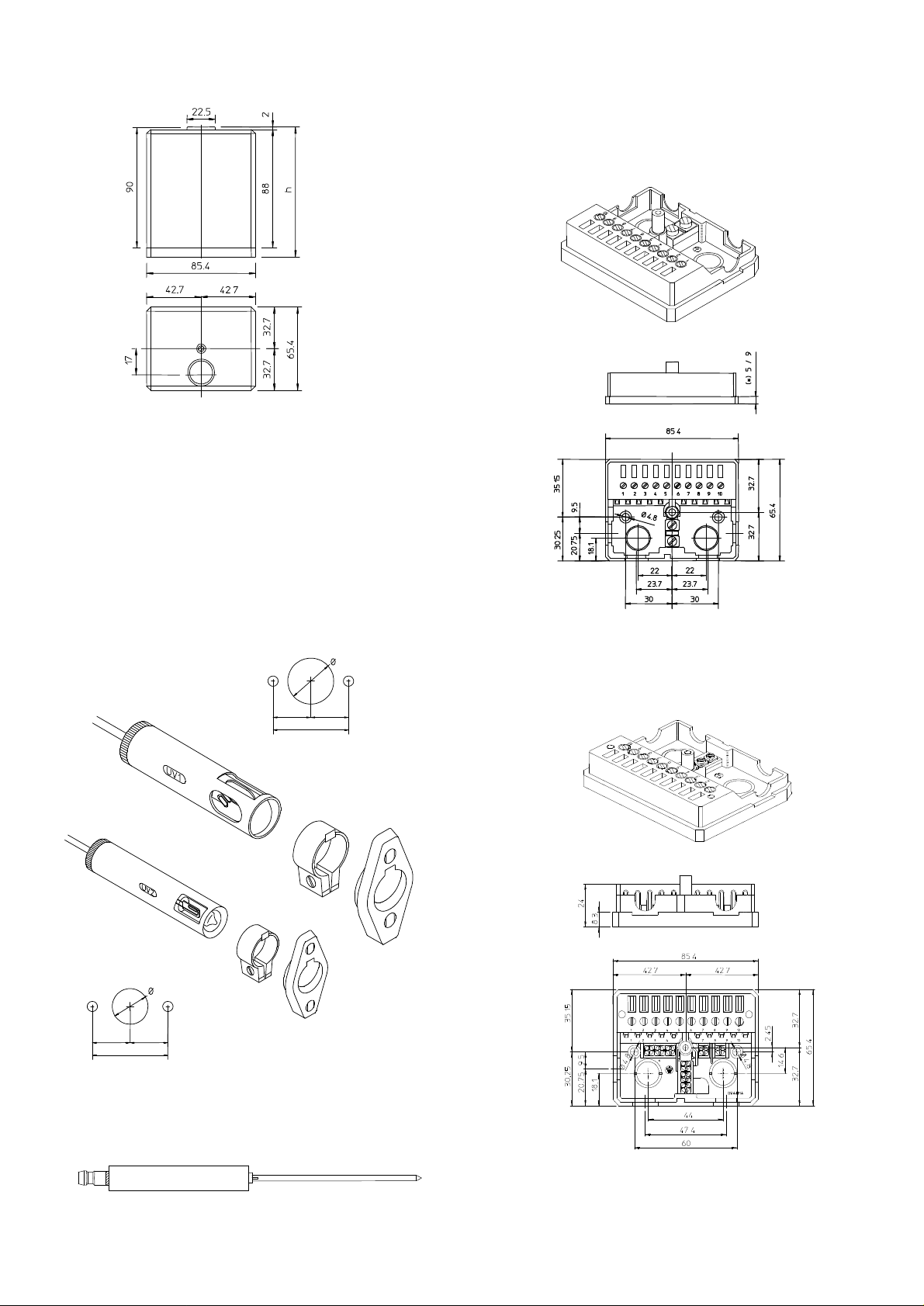
The main overall dimensions of the control box inclusive of
connecting sockets are shown in Fig.1.
CONNECTION
As regards the interconnection system of this control,
several solutions are possible and different types of
connecting sockets can be employed (see Fig.4 and Fig.5).
Socket NE differs from sockets D and E for its dimensions
and the greater number of terminals connecting neutral and
earth.
h: Dimensions depending on the type
of socket:
95 with socket D
99 with socket E
Fig.1
ACCESSORIES
The control is supplied with inbuilt reset button and lockout
signal.
It can be fitted with UV phototube sensors (see Fig.2) and
with kanthal flame detector probes in different executions
(see, for instance, Fig. 3).
Drilling plane UV1
22.5
(*) The dimensions differ depending on
the type of socket: 5 with socket D
18.5 18.5
37
M4 fixing screws
Sockets D - E
Fig.4
Drilling plane UV2
17.5
17
17
34
Fig.2
2/4 4015_r00
Fig.3
Socket NE
Fig.5
Page 3
DIRECTIONS FOR THE INSTALLATION
− Automatic controls are safety devices and must not be
opened. The manufacturer’s responsibility and
guarantee are invalidated if the control is opened.
− For technical and safety reasons a regulation shutdown
must occur every 24 hours.
− The control can be mounted in any position.
− Live and neutral should be connected correctly; a
mistake could cause a dangerous situation.
− Make sure that the discharge of the ignition transformer
does not hit the detection probe.
− The earth terminal of the control, the metal frame of the
burner, the earth of the ignition transformer and the
earth of the main supply must be well connected.
− The connecting wire of the detection probe must not be
longer than 20 meters.
− Avoid putting the detection cable close to power or
ignition cables.
− Use a heat resistant cable and detection probe, well
insulated to the ground and protected from possible
moisture (or water in general).
− Always check the control before the first start and also
after any replacing or after a long period of nonoperation of the system.
− In particular make sure that:
− The connections are corresponding to the above
scheme.
− The intervention of limiters or dafety devices
causes a safety shutdown according to the
application.
− The level of the flame signal is sufficient.
− A short circuit between detection probe and burner
casing does not cause any flame simulation.
− In running state a detection probe leakage to earth
causes the lockout of the control.
TIMERS
The safety time is obtained by an electronic circuit which
makes the TS vary of not more than 4% with voltage (-15%
+10%) and temperature (-10 +60°C) variations.
The prepurge time is given by a compensated thermic
timer. This timer, combined with the corresponding
electronic circuit, allows a minimum prepurge time of 30
seconds, even in case of voltage variations (-15 +10%),
ambient temperature variations (-10 +60°C), interruption of
the current supply for any time, or frequent and repeated
starts of the unit. A further timer causes a lockout after a
postpurge time of about 5 seconds.
OPERATING CYCLE
When thermostats and gas pressure switch are closed, the
control box supplies the burner motor and the TP timer (in
series with BF and the BRA relay supply module). During
this first period (TP heating) the BF checks its own state
and its supply network; a flame simulation in this phase
causes the interruption of the TP heating and the lockout of
the device within 5 seconds. If it works properly, the TP
heating causes the switching of 2TP (after about 15
seconds) and 1TP (after about 30 seconds) in succession.
The commutation of 1TP stops the supply to TP, BF and
BRA, starting in this way the second stage (TP cooling):
The delay in the deenergization of BRA enables the BRB
relay to be supplied (through 1TP and 1A contacts) and to
restrain through 1B and PA.
If the PA contact is open (air flow failure), the
deenergization of the BRA relay is followed by the
deenergization of the BRB relay, therefore the device does
not continue its cycle, but remains in the prepurge stage. If
it works properly (PA closed), the energization of the BRB
relay is followed by the supply of the BRC relay: this stage,
with the cooling of TP, allows a minimum prepurge of 30
seconds.
The interruption of the electrical supply, or the temporary
opening of the air pressure switch, cause the repetition of
the whole starting cycle. In case of regular operation, the
4015_r00 3/4
TP cooling brings 1TP back to the starting position, and
with the BRB and BRC relay contacts in operating state,
the ignition stage begins, with the contemporary supply of
the BF thermal, of the ignition transformer and of the EV1
valve.
The ignition transformer and the EV1 valve are only
supplied during the safety time, which is determined by the
deenergization of BRC, taking place after 2 seconds; if the
burner starts operating within this delay, the BRF flame
relay contacts (1RF and 2RF) are switched, stopping the
supply to the BF lockout thermal and keeping the EV1
valve energized. The operating cycle is completed with the
EV2 valve control, provided after about 30 seconds by 2TP
going back to the starting position.
Flame failure prevents the commutation of 1RF and 2RF,
therefore at the end of the safety time only the BF lockout
thermal is still supplied, causing a lockout after 3 seconds.
If the flame extinguishes in normal running state, the
control closes both valves in less than 1 second and
performs a lockout after a postpurge time of about 5
seconds.
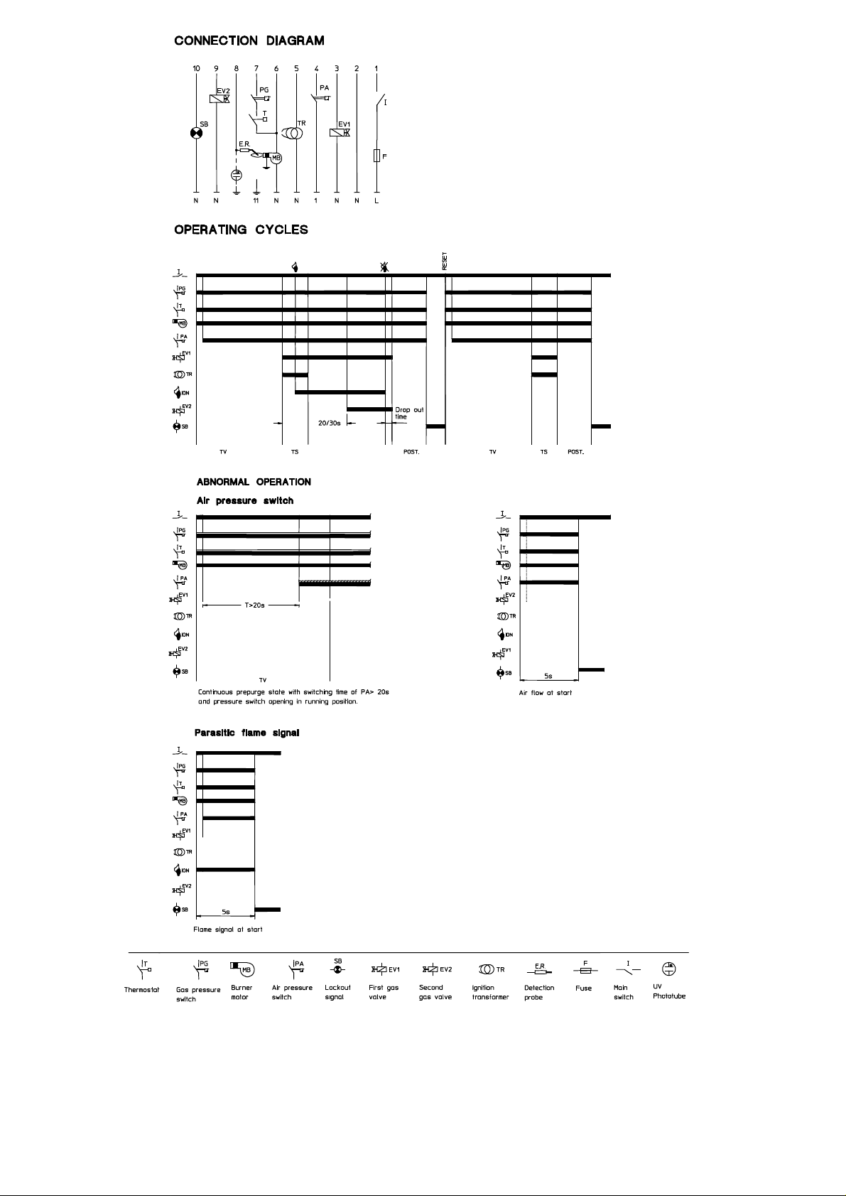
Abnormal operation:
− Air flow at start
The control performs a lockout within 5 seconds.
− Air flow failure at start
If the pressure switch is not commuted within 20
seconds, the prepurge stage continues.
− Air flow failure in running position
If the pressure switch contact opens, the device begins
the prepurge stage, which continues until the pressure
switch contact is open.
− Parasitic flame
The presence of a parasitic signal flame at start, or a
fault in the flame detection circuit leading to the same
condition, cause a lockout within 5 seconds.
CAUTION: If for any reason the burner system is not
equipped with air pressure switch, terminals n.4-6 must be
short-circuited instead of n.4-1. If terminals n.4-1 were
short-circuited, the control box would always perform a
lockout because of a stuck-contact simulation.
RESET OF THE CONTROL
To reset the control after a lockout, act on the button after
waiting for the restoration of the lockout thermal, which
normally takes about 20 seconds.
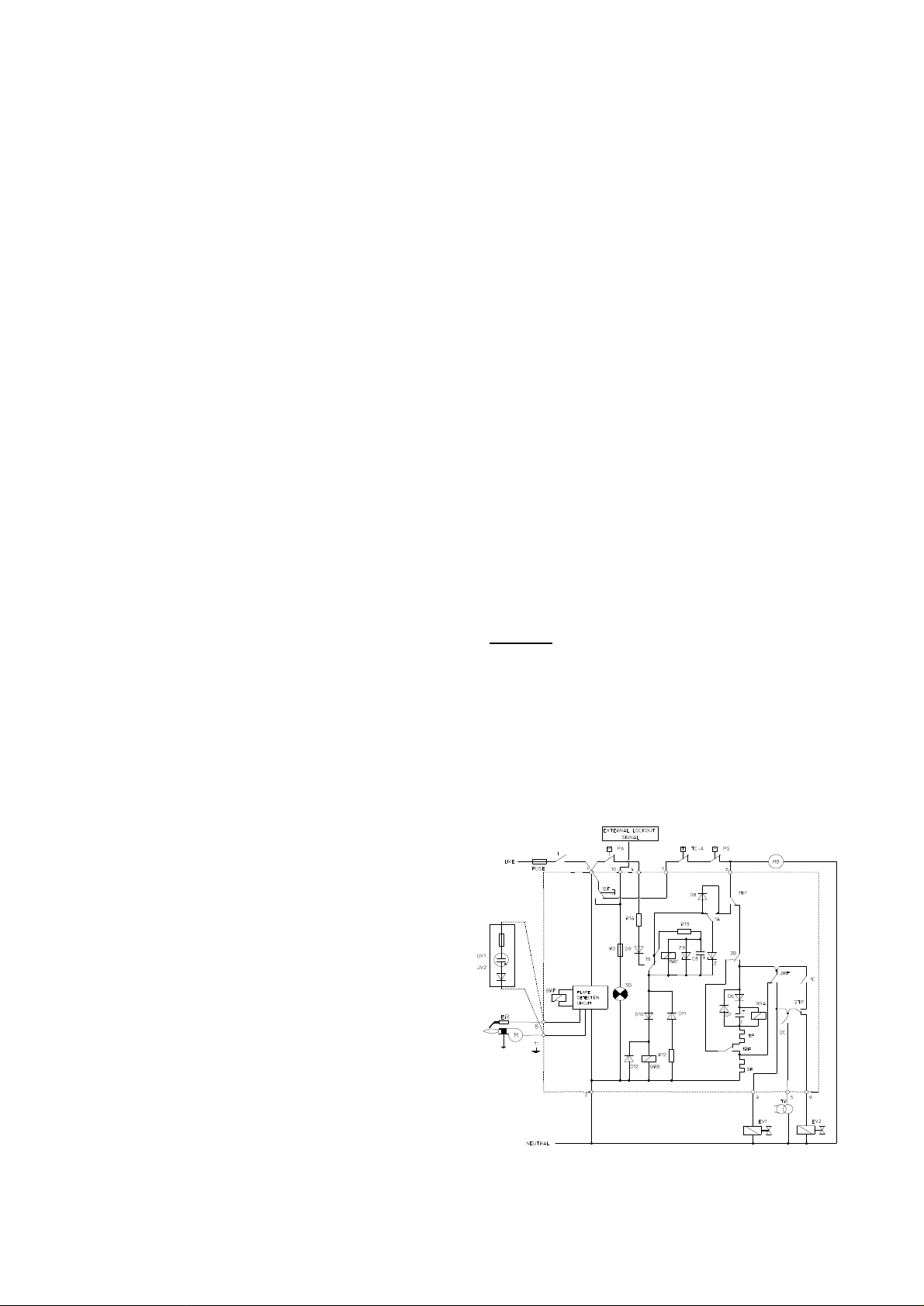
ELECTRICAL SCHEME
BF: Lockout and postpurge thermal M: Burner casing
BRA: Granted prepurge relay MB: Burner motor
BRB: Operation relay PA: Air pressure switch
BRC: Safety time relay PG: Gas pressure switch
BRF: Flame detection relay SB: Lockout signal
ER: Detection probe TP: Thermal programmer
EV1: First gas valve TC-A: Thermostats
EV2: Second gas valve UV1 UV2: Phototube
Page 4
without
BRAHMA S.p.A.
Via del Pontiere, 31
37045 Legnago (VR)
Tel. +39 0442 635211 - Telefax +39 0442 25683
http://www.brahma.it
E-mail : [email protected]
4/4 4015_r00
03/03/26 Subject to amendments
notice
 Loading...