

Braeburn Premier 3100 User Manual
MODEL
3100
USER MANUAL
Compatible with low voltage multi-stage
heat / cool systems with up to two stages of
heating and two stages of cooling.
READ ALL INSTRUCTIONS BEFORE PROCEEDING
© 2005 Braeburn Systems LLC • Patents Pending • All Rights Reserved. Pub. No. 3100-100-006
WARNING!
Important Safety Information
• Always turn off power to the air conditioning or heating system prior to
installing, removing, cleaning or servicing thermostat.
• Read manual thoroughly prior to installing, programming or operating thermostat.
• This thermostat is designed for use with a 24 Volt-AC low voltage multi-stage
heat / cool system.
• Do not use this thermostat on systems with voltages higher than 30 Volt-AC.
• This thermostat requires 24 Volt AC power for normal operation and control of
the heating or cooling system.
• Wiring must conform to all building codes and ordinances as required by local
and national code authorities having jurisdiction.
• Do not short (or jumper) across terminals on the gas valve or at the heating or
cooling system control board to test the thermostat installation. This could
damage the thermostat and void the warranty.
• Do not select COOL mode of operation if the outside temperature is below 50˚ F
(10˚ C). This could possibly damage the controlled cooling system and may
cause personal injury.
• This thermostat should only be used as described in this manual. Any other use
is not recommended and will void the warranty.
SPECI FICAT IONS
1
• Electrical Rating: 24 Volt AC (18-30 Volt AC)
2 amp maximum load per terminal
4 amp total maximum load (all terminals)
• Control Range: 45˚ - 90˚ F (7˚ - 32˚ C)
• Accuracy: +/- 1˚ F (+/- .5˚ C)
• AC Power: 18-30 Volt AC
• Compatibility: Multi-stage heat / cool systems with up to two stages of heating
and two stages of cooling.
• Terminations: R, Y1, Y2, W1, W2, G, O, B, C
INSTA L LATI O N
2
2.1
Replacing Existing Thermostat
1.
Always turn off power to the air conditioning or heating system prior to removing
existing thermostat.
2.
Remove the cover of your old thermostat and locate the wire terminals. Do not
remove wires from terminals yet.
3.
Using small pieces of masking tape label wires prior to removal from terminals. Use
the chart below to determine the new terminal designations for your new thermostat.
4.
After labeling and removing all wires from terminals, unscrew the existing thermostat
sub-base from wall. Make sure to secure wires to prevent them from slipping back
into the hole in the wall.
Old Terminal from New Terminal for
Existing Thermostat New Thermostat Terminal Description
R, V-VR or VR-R R 24 VAC
Y, Y1 or M Y1 1st Stage Cooling
Y2 Y2 2nd Stage Cooling
W1 W1 1st Stage Heating
W2 or W-U W2 2nd Stage Heating
G or F G Fan Control
O or R O Reversing Valve (Cooling)
B B Reversing Valve (Heating)
C, X or B C Transformer Common
Premier Series
Non-Programmable
2 Heat / 2 Cool & Heat / Cool
Digital Thermostat
CONTENTS
SP ECI FIC ATIO NS
IN STAL L ATIO N
TE STI NG YOUR NE W T HERM OSTAT
PR OGR AMM ING USE R S ETTI NGS
AD DIT ION AL O PER ATIO N F EATU R ES
TR OUB LES HOOT ING
WI RIN G D IAGR AM
1
2
3
4
5
6
7
1
2 3
INSTA L LATI O N
2
2.1
Replacing Existing Thermostat cont.
Installing Your New Thermostat
NOTE: If you are installing this thermostat in a new installation be sure to locate
the thermostat 4 to 5 feet above the floor in accordance with applicable building
codes. Make sure to install the thermostat in a location that provides good airflow
characteristics and avoid areas behind doors, near corners, air vents, direct sunlight
or near any heat generating device. Installation in any of these areas could impact
thermostat performance.
1.
Always turn off power to the air conditioning or heating system prior to
installing thermostat.
2.
Place system switch on front of thermostat to OFF position.
3.
Place fan control switch on front of thermostat to AUTO position.
4.
Remove front of thermostat from sub-base by pressing release latch on bottom
of thermostat.
5.
Place the thermostat sub-base against wall in the desired thermostat location.
6.
Guide thermostat wires through center hole in sub-base. Continue to hold
against wall.
7.
Mark placement of mounting holes and drill using a 3/16" drill bit. Gently tap supplied
plastic anchors into the holes in the wall.
8.
Place the sub-base against the wall in the desired location, making sure the mounting
holes are aligned and the thermostat wires are properly inserting through opening
in sub-base.
NOTE: This thermostat is for use on low voltage 24 Volt AC multi-stage heat / cool
systems with up to two stages of heating and two stages of cooling and requires a
transformer common wire for proper installation. This thermostat is not for use on
single stage heating or cooling systems.
TESTING YOUR
NEW THERMOSTAT
3
NOTE: Test your thermostat prior to programming any user settings. Pressing the
RESET button will erase any user entries previously programmed. This will erase all
user settings and return them to their default values.
WARNING!
Read BEFORE Testing
1. Place the system switch in the HEAT position.
2. Press the button on the keypad until the setpoint temperature setting is a minimum of 3 degrees
higher than the current room temperature. The heating system should start within several seconds.
The fan may not turn on immediately due to the heating system built-in fan delay.
3. Place the system switch in the OFF position. The heating system should stop within
several seconds.
4. Place the system switch in the COOL position.
5. Press the button on the keypad until the setpoint temperature is a minimum of 3 degrees lower
than the current room temperature.
6. The cooling system should start within several seconds. Place the system switch in the OFF
position. The cooling system should stop within 90 seconds (dependent on the setting of the
Residual Cooling Fan Feature).
7. Place the fan switch in the ON position. The system blower should start.
8. Place the fan switch in the AUTO position. The system blower should stop.
• Do not short (or jumper) across terminals on the gas valve or at the heating or cooling
system control board to test the thermostat installation. This could damage the
thermostat and void the warranty.
• Do not select COOL mode of operation if the outside temperature is below 50˚ F
(10˚ C). This could possibly damage the controlled cooling system and may cause
personal injury.
• This thermostat includes an automatic compressor protection feature to avoid potential
damage to the system from short cycling. This thermostat automatically provides a
5-minute delay after turning off the cooling system output to protect the compressor.
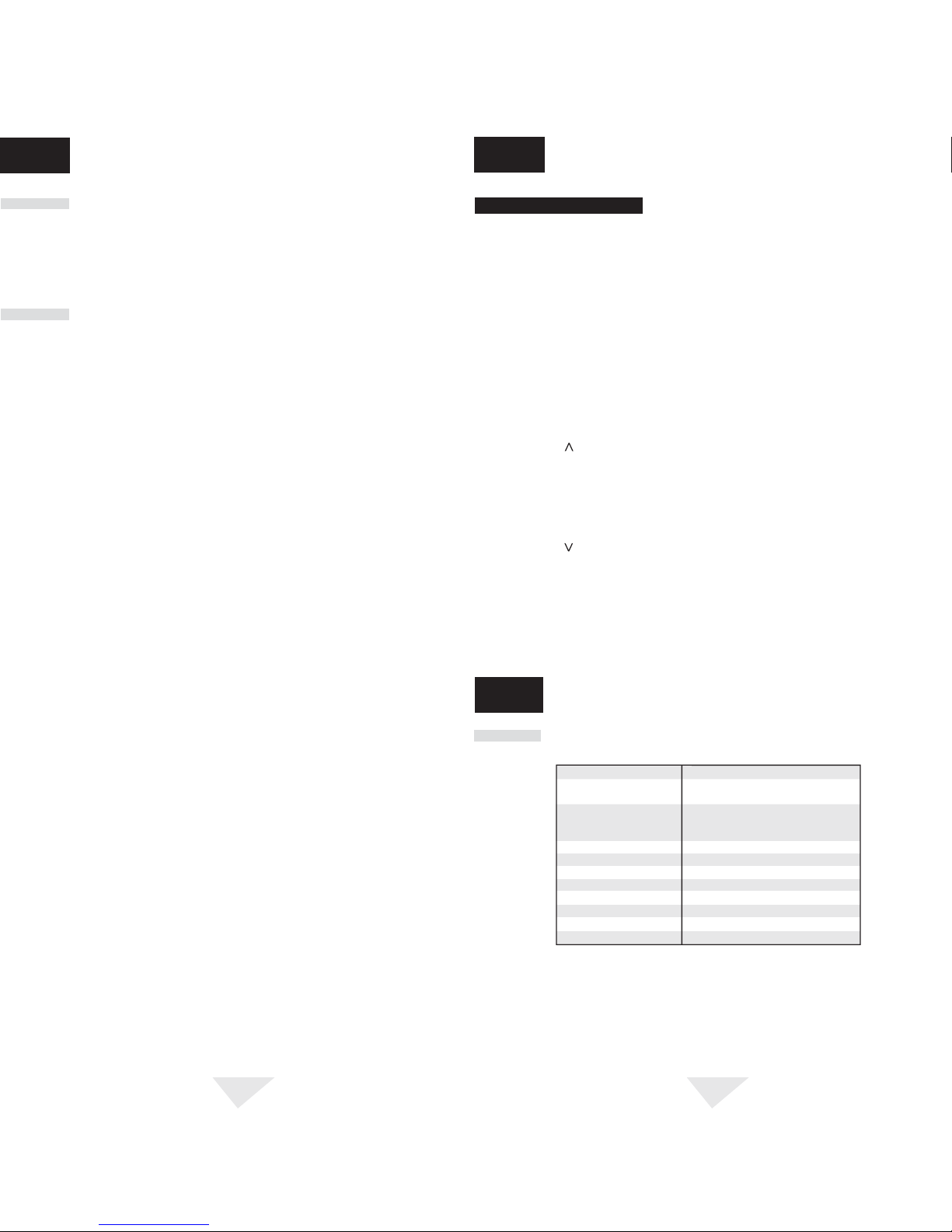
4.1
Default Thermostat Settings
Function Status After Reset
Operation Mode Normal Operating Mode
Room Temperature 70˚ F (21.0˚ C), to be renewed within
5 seconds
Setpoint Temperature According to system switch:
62˚ F (17.0˚ C) for Heat and Off
85˚ F (29.0˚ C) for Cool
Temperature Scale ˚F or ˚C dependent on switch setting
First Stage Differential .5˚ F (0.25˚ C)
Second Stage Differential 2˚ F (1.0˚ C)
Residual Cooling 60 Seconds
Short Cycle Protection Timer Reset
Output Relays Off
Recirculating Fan Timer Reset with 120 minute off cycle
Keypad Lock Unlocked
co n t.
2.2
9. Fasten the sub-base to wall using supplied screws.
10. Connect wires to quick wiring terminal block as appropriate using the new terminal
designations. Refer to Wiring Diagram section of this manual if required for assistance.
11. Make sure all of the wire connections are secure and are not touching any other
terminal to prevent electrical shorts and potential damage to the thermostat.
12. Turn the front thermostat body over exposing the rear view of the circuit board.
13. Locate the internal ˚F / ˚C switch on the circuit board.
14. Using your finger, gently flip the switch toward the preferred temperature ˚F / ˚C scale.
15. Locate the internal fan option switch, HG (Gas) / HE (Elec) on the circuit board. This
switch controls the heating system fan delay. Select gas for gas or oil fired systems.
This will allow the furnace to run for a few seconds before initiating the fan. Select
electric for systems with electric furnace elements that require the fan to come
on immediately.
16. Using your finger, gently flip the switch towards the HG (gas) or HE (Elec) selection
which indicates the low voltage heating system the thermostat will control.
17. Attach front body of thermostat to sub-base of thermostat being careful to align the
terminal pins on the front body with the terminal block on the sub-base.
18. Restore system power so you can test installation.
PROGR AMMI N G
USER SETT I NGS
4
 Loading...