

Page 1
Installation
THIS
SIDE
UP
Packing List
•
•
•
•
Installation
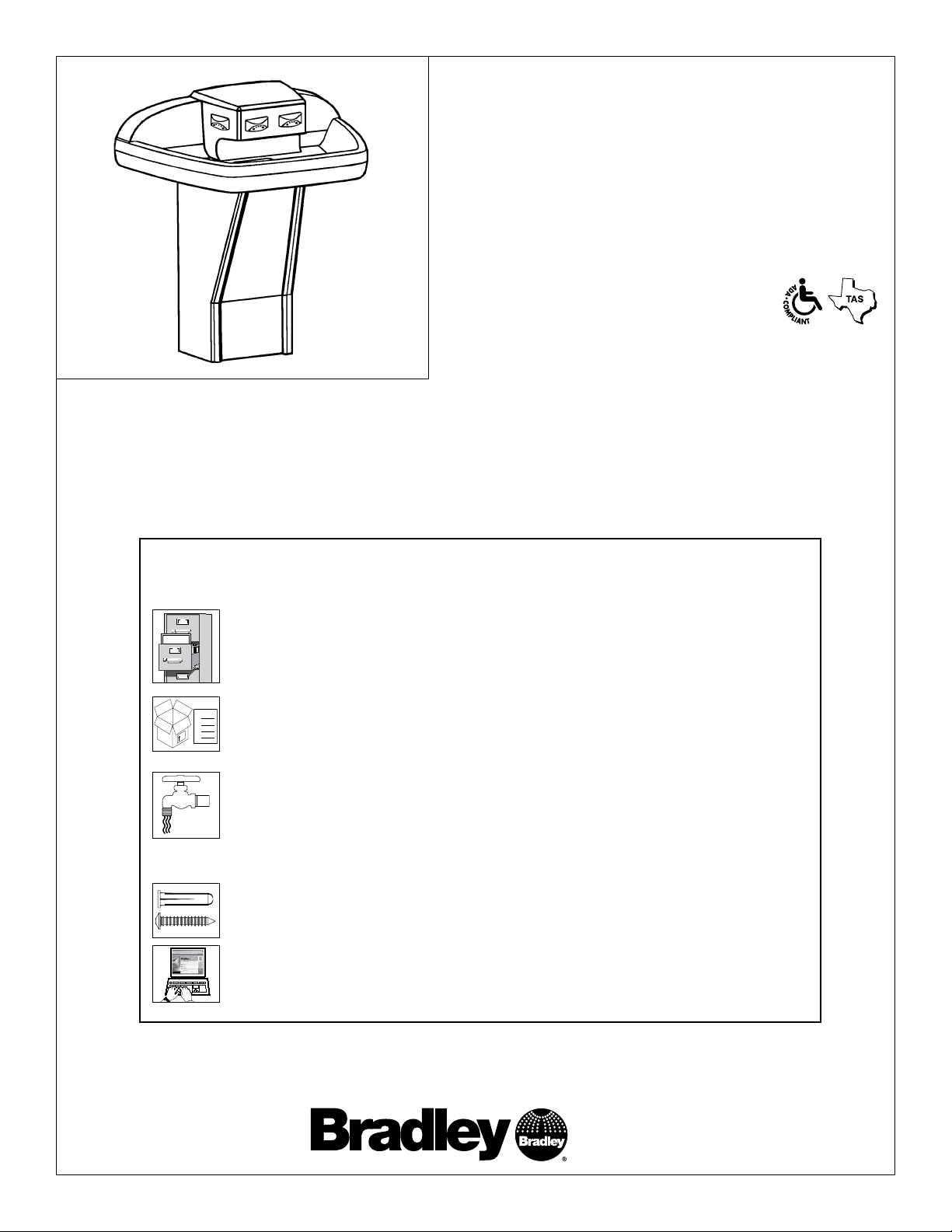
MF2944/BIR3
Terreon® Quadra-Fount™ Washfountain
with Battery Operated Infrared Control
(Standard*, Juvenile and OBC Height)
* Standard Height is ADA/TAS Compliant
Table of Contents
Pre-Installation Information .......................... 2
Parts Included with the Quadra-Fount
Installation Instructions ............................4-9
Cleaning and Maintenance .......................10-11
Troubleshooting................................12-14
™
................. 3
IMPORTANT!
Read this entire installation manual to ensure proper installation. When
finished with the installation, file this manual with the owner or maintenance
department.
Separate parts from packaging and make sure all parts are accounted for
before discarding any packaging material. If any parts are missing, do not
begin installation until you obtain the missing parts.
Water supply requires a flowing pressure of at least 20 psi, but no greater
than 80 psi.
Make sure that all water supply lines have been flushed and then completely
turned off before beginning installation. Debris in supply lines can cause
valves to malfunction.
215-1373 Rev. P; ECN 14-00-006
© 2014 Bradley
Page 1 of 14 6/6/2014
Hardware supplied by installer must be appropriate for wall construction. Wall
anchors used must have a minimum pull-out rating of 1,000 lbs.
Product warranties may be found under “Product Information” on our web site
at www.bradleycorp.com.
P.O. Box 309, Menomonee Falls, WI 53052-0309
Phone: 1-800-BRADLEY Fax: (262) 251-5817
http:\\www.bradleycorp.com
Page 2

MF2944/BIR3 Installation
Supplies Required by Installer
• (6) 3/8" diameter bolts with washers and (6) wall anchors appropriate for your installation
• (2) 3/8" diameter bolts with washers and (2) floor anchors appropriate for your installation
• 1/2" nominal copper tubing for hot and cold water supply lines
• 1-1/2" NPT drain trap and waste connection
• Pipe sealant and plumber’s putty
Pre-Installation Information
Terreon material
The Quadra-Fount is constructed of Terreon, a densified solid surface material composed of polyester resin. Terreon is
resistant to chemicals, stains, burns and impact. Surface damage can be easily repaired with everyday cleaners or fine-grit
abrasives. Terreon is NAHB certified to meet ANSI Z124.3, Z124.6 and ANSI/ICPA SS-1-2001.
Infrared sensor and 6V DC solenoid valve
Each sprayhead is controlled by a 6V DC solenoid valve, allowing each user to activate a single flow of water. Each valve
uses less than half the maximum amount of hot water allowed by the ANSI/ASHRAE/IES 90A-1980 Standard.
Barrier-free and ADA compliant
The Terreon Quadra-Fount with infrared is designed to comply with all ADA and TAS guidelines on reaches, clearances and
operation when mounted at standard height dimensions by the installer.
2 6/6/2014 Bradley • 215-1373 Rev. P; ECN 14-00-006
Page 3
Installation MF2944/BIR3
Hose-Stop Preapack - TMA
S45-2730
Stop
Hose
Battery Holder
Battery
Hose-Stop Prepack - TL
S45-2731 (optional)
Stop
Hose
Valve Assembly with
Two Mounting Screws
MOUNTING PANELS
LOWER BRACKET
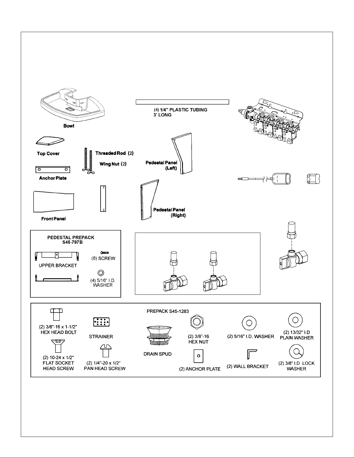
Parts included with the Quarda-Fount
™
Separate all parts from packaging materials and ensure you have all the parts required for assembly. If any parts are
missing, do not attempt to assemble the Bradley Terreon® Quarda-Fount™ Washfountain until you obtain all parts.
Bradley • 2215-1373 Rev. P; ECN 14-00-006 6/6/2014 3
Page 4
MF2944/BIR3 Installation
MOUNTING
PANEL
1/4"-20 x 1/2"
PAN HEAD
SCREW
1/4"-20 x 1/2"
PAN HEAD
SCREW
5/16" I.D.
WASHER
LEFT
PEDESTAL
PANEL
UPPER
BRACKET
LOWER
BRACKET
CENTERLINE OF
FIXTURE
RIGHT
PEDESTA
L
PANEL
1
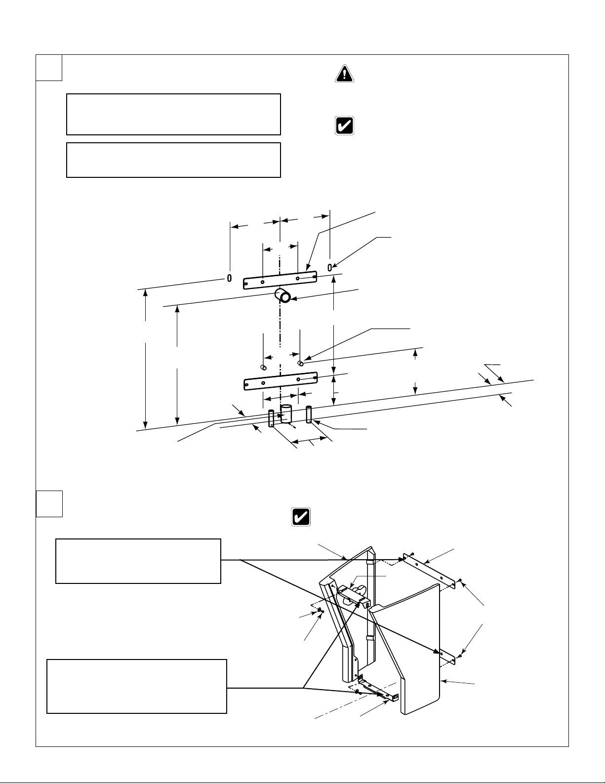
Rough-Ins
Rough in 1/2" nominal copper tubing for hot
and cold supply lines through wall or floor at
A
dimensions shown.
Rough in 1-1/2" NPT drain waste connection
B
through wall or floor at dimensions shown.
Flush the supply lines before making
connections. Debris in supply lines will
cause the valves to malfunction.
Compliance and conformity to local codes and
ordinances is the responsibility of the installer.
28" (711) STD
27" (686) OBC
24" (610) JUV
24" (610) STD
23" (584) OBC
20" (508) JUV
1-1/2" NPT Waste Connection (Optional) -
3" From Wall - Stub Out 3"
(76)
Mounting Panels
(2) Appropriate Anchors and 3/8" Bolts
(Supplied By Installer) To Mount Bowl To Wall
1-1/2" NPT Waste Connection For Use With
1-1/2" Tubular P-Trap, Stub Out Min. 1-1/2"
1/2" Nominal Copper Tubing For
Supplies, Stub Out Min. 1-1/2" from Wall
9-1/2" (241) STD
8-1/2" (216) OBC
5-1/2" (140) JUV
1/2" Nominal Copper Tubing For Supplies (Optional) -
5" From Wall, Stub Out Min. 1-1/2"
5"
(127)
Finished Floor
7"
(178)
7-1/2"
(191)
11"
(279)
7"
(178)
7-1/2"
(191)
19-1/2"
(495)
7-1/8" (181) STD
6-1/8" (156) OBC
3-1/8" (79) JUV
11"
(279)
3"
4 6/6/2014 Bradley • 215-1373 Rev. P; ECN 14-00-006
2
Assemble Pedestal
Fasten the mounting panels to
the pedestal with four pan head
A
1/4"- 20 x 1/2" screws supplied.
Install the upper and lower brackets
to the pedestal panels with two pan
B
head 1/4"- 20 x 1/2" screws and
5/16" I.D washers supplied.
Washers are not utilized on back of mounting panels.
Page 5
Installation MF2944/BIR3
ASSEMBLY
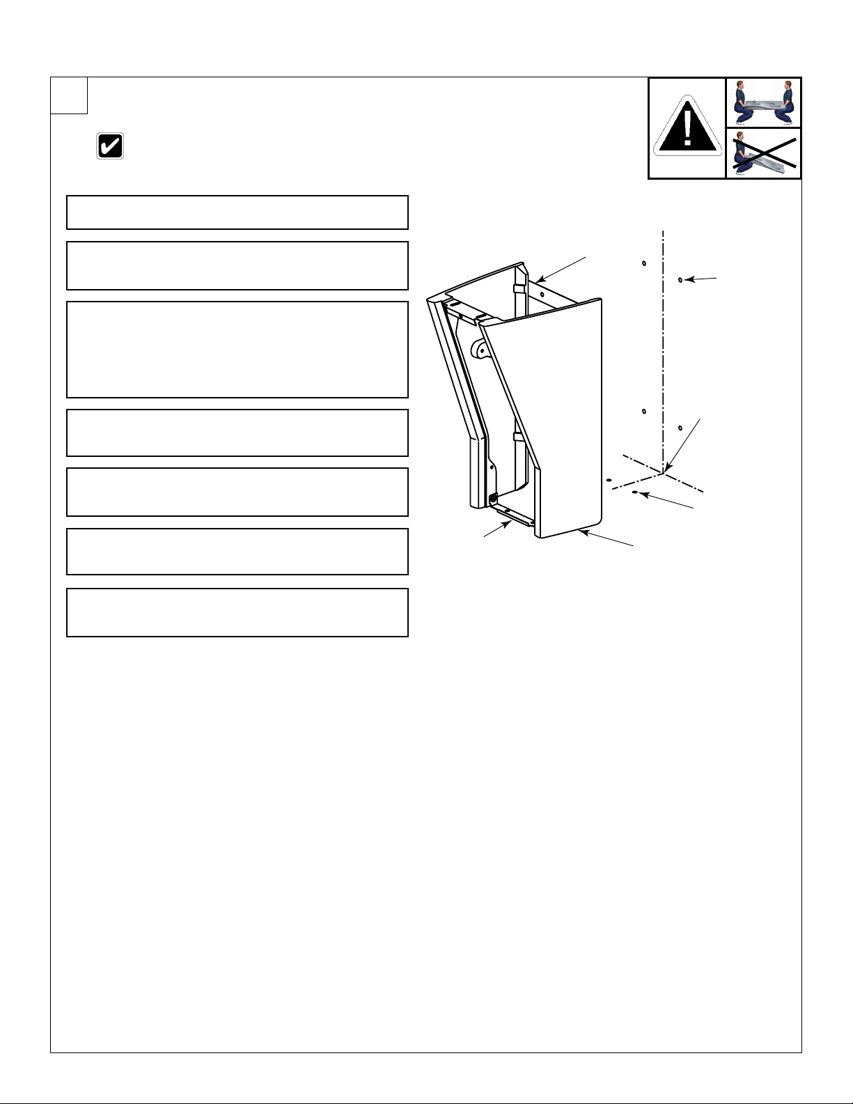
3
Install Pedestal
Remove molding strips or tiles which could
prevent a flush mounting to the wall.
Measure and mark the centerline of the washfountain
A
on the wall and floor.
Before mounting the pedestal to the floor, make sure
the floor is level. If it is not level, be prepared to install
B
shims when positioning the pedestal in Step C.
With someone to assist you, move the pedestal
assembly to the wall using appropriate lifting
procedures, and align the locating notches on the
C
mounting panel with the centerline marked on the
wall. If the floor is not level, install shims under the
left and/or right pedestal.
Drill holes in the wall through the four 1/2" diameter
holes in the mounting panel and install four anchors
D
(supplied by installer) for 3/8" bolts.
Secure the pedestal assembly to the wall anchors
using four 3/8" bolts and washers (supplied by
E
installer).
Drill holes in the floor through the two 1/2" diameter
holes in the lower bracket and install two anchors
F
(supplied by installer) for 3/8" bolts.
After floor anchors are installed, secure the pedestal
assembly to the floor anchors using two 3/8" bolts
G
and washers (supplied by installer).
LOWER
BRACKET
MOUNTING
PANEL
PEDESTAL
WALL ANCHOR
LOCATION
CENTERLINE
FLOOR ANCHOR
LOCATION
Bradley • 2215-1373 Rev. P; ECN 14-00-006 6/6/2014 5
Page 6

MF2944/BIR3 Installation
4
Install Solenoid Assembly
The letter "H" on the Navigator® mixing
valve indicates hot water supply inlet.
Attach the stops to hot and cold water rough-ins.
A
1/4" - 20 x 1/2"
Connect one end of each supply hose to the stops.
B
Inside the pedestal, install the two 1/4" - 20 x
1/2" screws (supplied with valve assembly) in the
mounting holes on the side of the left pedestal panel.
C
Do not thread the screw completely into the panel,
but allow 5/16" of the screw to be exposed.
Screws
Solenoid Valve
Assembly
Supply Hose
Connect the other end of each supply hose to the
Navigator
D
one of the cold side).
Mount the valve bracket to the left side of the
E
pedestal.
For optional single tempered supply: attach the
stop to the 1/2" tempered supply line. Connect
the stop to the solenoid valve assembly with the
F
flexible supply hose.
®
TMV valve assembly (one on the hot side,
Navigator TMV
Hot Supply
Inlet
Cold Supply
Stop
Inlet
6 6/6/2014 Bradley • 215-1373 Rev. P; ECN 14-00-006
Page 7

Installation MF2944/BIR3
5
Assemble and Install Bowl
Do not leave the bowl on the pedestal unsupported, as it
may fall and cause personal injury or damage to property.
Discard rubber gasket included with drain spud. It cannot be
used in this application.
Install two 3/8" wall anchors (supplied by installer)
which will be used to mount the bowl to wall (see
A
rough-ins on page 4).
Carefully remove the sprayhead cover.
B
Carefully lift the bowl onto the pedestal frame using
appropriate lifting procedures. Ensure bowl remains
C
3-4” from the wall.
Install the two wall anchor brackets to the back of
the bowl using the 3/8"- 16 x 1-1/2" hex-head bolts,
D
13/32" I.D. plain washers, anchor plates, 3/8" I.D.
lockwashers, and 3/8"- 16 hex nuts provided.
Uncoil the infrared sensor leads and plastic tubing
E
from the rear of the backsplash.
Slide the bowl back to the wall and secure the bowl’s
wall brackets to the wall anchors with two 3/8" bolts
F
and washers (supplied by installer).
Dome Strainer
Back View of Washfountain Bowl
Drain Assembly
Screws for Strainer
#10-24 x ½"
Fasten the bowl to the upper bracket on the pedestal
assembly with the two 1/4"- 20 x 1/2" round-head
G
screws and 5/16" I.D. washers supplied.
Install the drain spud in the bowl using plumber’s
H
putty.
From beneath bowl, thread the spud washer and
spud locknut onto the drain spud and tighten the
I
locknut against the bowl.
Install strainer in the bowl drain using the two #10-24
J
x 1/2" flat socket head screws supplied.
Connect the drain trap (supplied by installer) to the
K
drain spud and drain line.
Drain Spud
Spud Washer
Spud Locknut
Washfountain Bowl
Discard this washer;
it is not used on
washfountains
Bradley • 2215-1373 Rev. P; ECN 14-00-006 6/6/2014 7
Page 8

MF2944/BIR3 Installation
6
Electrical and Supply Connections
Sensor cables must be attached before the battery cables are plugged into the
circuit boards.
Connections of leads other than shown may cause permanent damage to the sensor.
Insert 4 different colored sprayhead
supply tubes into four solenoid tube
connectors by loosening tube connector
A
cap and firmly pushing tubing into tube
connector until the tubes are fully seated,
then re-tighten connector cap.
Connect the sensor cable from the right
hand station to the circuit board attached
B
to the solenoid with the yellow supply
tube.
Connect the sensor cable from the
right center station to the circuit board
C
attached to the solenoid with the black
supply tube.
Connect the sensor cable from the left
center hand station to the circuit board
attached to the solenoid with the green
D
supply.
Connect the sensor cable from the left
hand station to the circuit board attached
E
to the solenoid with the red supply.
Solenoid Assembly
Navigator Mixing
Valve
Supply Inlet
Yellow Supply Tube
(from Sprayhead)
Black Supply Tube
(from Sprayhead)
Battery Cable
Green Supply Tube
(From Sprayhead)
Red Supply Tube
(From Sprayhead)
Solenoid
Connector
Compression
Nut
Sensor Cable
Insert the batteries into the battery
holders and then mount the battery
F
holders (with batteries) in a convenient
location in the pedestal.
Snap the battery connector cables into
G
the circuit board plugs.
8 6/6/2014 Bradley • 215-1373 Rev. P; ECN 14-00-006
Battery Holder (S83-177)
6-Volt Lithium Battery
Type DL223A or Equivalent
(261-010)
Page 9

Installation MF2944/BIR3
LOWER
BRACKET
FRONT
PANEL
SCREW
UPPER
BRACKET
7
Check Operation
Check to make sure both stops are fully
A
open (see page 6).
This valve is NOT factory preset. Upon installation, the
Turn on the main water supply to the
B
Quadra-Fount and check for leaks.
Turn on the electrical power and pass
your hand in front of each sensor until air
C
is purged from the lines.
Loosen Cap Screw about ¼" (4-6 turns)
D
and lift up cover (do not remove).
temperature of this valve must be checked and adjusted
to ensure delivery of a safe water temperature. Water in
excess of 110°F (43°C) may cause scalding.
Using cover, turn cartridge gently until
desired water temperature is reached. Do
E
not turn past stops as this may damage
unit. Push cover down and tighten screw.
8
Install Top Cover and Front Panel
Carefully place the top cover with
threaded rods on top of washfountain
A
sprayhead.
Inside the pedestal assembly of the
washfountain (use front access), slide
the anchor plate onto the threaded rods
B
and secure anchor plate against bowl
using the wing nuts provided.
To install front panel, slip slot in bottom
of front pedestal panel over the lip on the
C
lower bracket,
H
C
Secure panel to upper bracket with
D
Bradley • 2215-1373 Rev. P; ECN 14-00-006 6/6/2014 9
attached screw.
Page 10

MF2944/BIR3 Installation
Cleaning and maintenance instructions for Terreon
Material Description: Terreon is an NAHB Certified densified solid surface material composed of polyester resin and is resistant to
chemicals, stains, burns and impact. Surface damage can be easily repaired with everyday cleansers or fine grit abrasives.
Routine Cleaning: Clean daily or as often as conditions require using a standard commercial or household cleaner such as Formula
®
or Windex®.
409
®
Stubborn Stains: Remove tough stains with Ajax
, Comet®, or Soft-Scrub® and a green Scotch-Brite® pad or lightly sand in a circular
motion with 240 grit wet/dry sandpaper. The finish can be renewed with a maroon Scotch-Brite pad.
Special Situations for Material
Scratches: Remove scratches with a green Scotch-Brite® pad. The finish can then be renewed with a maroon Scotch-Brite® pad.
Hard Water Deposits: Remove hard water deposits with a mild solution of vinegar and water. Always rinse the unit thoroughly after
cleaning.
®
Restoring the surface: Use Hope’s
Bradley recommends additional care and maintenance for the darker colored Terreon. For complete instructions on this additional
maintenance see Bradley document #1505.
Do not use strong acid or alkaline chemicals and cleansers to clean Terreon. If these chemicals come in contact with
the terreon surface, wipe them off immediately and rinse with soapy water.
Avoid contact with harsh chemicals such as paint remover, bleach, acetone, etc. Avoid contact with hot pans and
objects.
Repair Kits: Terreon repair kits are available. Contact your Bradley representative or distributor for part numbers and pricing.
Solid Surface cleaner and polish to refresh and protect the Terreon Solid Surface material.
Repair kits are made to order and have a shelf life of 30 days.
Brand Names: Use of brand names is intended only to indicate a type of cleaner. This does not constitute an endorsement, nor does
the omission of any brand name cleaner imply its inadequacy. Many products named are regional in distribution, and can be found in
local supermarkets, department and hardware stores, or through your cleaning service. It is emphasized that all products should be
used in strict accordance with package instructions.
When cleaning units equipped with infrared (electronic eye) activation, it is helpful to turn off the power to the unit or cover the
windows to prevent accidental activation. After the window is covered, the water will run for approximately 30 seconds and then
shut off.
10 6/6/2014 Bradley • 215-1373 Rev. P; ECN 14-00-006
Page 11

Installation MF2944/BIR3
Cleaning and maintenance instructions for stainless steel
Material Description: Stainless steel is extremely durable, and maintenance is simple and inexpensive. Proper care, particularly
under corrosive conditions, is essential. Always start with the simplest solution and work your way toward the more complicated.
Routine cleaning: Daily or as often as needed use a solution of warm water and soap, detergent, or ammonia. Apply the cleaning
solution per the manufacturer’s instructions and always use a soft cloth or sponge to avoid damaging the finish.
®
Stubborn Stains: To remove stains from stainless steel use a stainless steel cleaner and polish such as Ball
or a soft abrasive. Always follow the manufacturer’s instructions and apply in the same direction as the polish lines.
Never use ordinary steel wool or steel brushes on stainless steel. Always use stainless steel wool or stainless steel
brushes.
stainless steel cleaner
Special Situations for Material
Fingerprints and Smears: To remove fingerprints or smears use a high quality stainless steel cleaner and polish in accordance with
the manufacturer’s instructions. Many of these products leave a protective coating that helps prevent future smears and fingerprints.
Grease and Oil : To remove grease and oil use a quality commercial detergent or caustic cleaner. Apply in accordance to the
manufacturer’s instructions and in the direction of the polish lines.
Precautions: Avoid prolonged contact with chlorides (bleaches, salts), bromides (sanitizing agents), thiocyanates (pesticides,
photography chemicals, and some foods), and iodides on stainless steel equipment, especially if acid conditions exist.
Do not permit salty solutions to evaporate and dry on stainless steel.
The appearance of rust streaks on stainless steel leads to the belief that the stainless steel is rusting. Look for the actual source of
the rust in some iron or steel particles which may be touching, but not actually a part of the stainless steel structure.
Strongly acidic or caustic cleaners may attack the steel, causing a reddish film to appear. The use of these cleaners should
be avoided.
Brand Names: Use of brand names is intended only to indicate a type of cleaner. This does not constitute an endorsement, nor does
the omission of any brand name cleaner imply its inadequacy. Many products named are regional in distribution, and can be found in
local supermarkets, department and hardware stores, or through your cleaning service. It is emphasized that all products should be
used in strict accordance with package instructions.
Bradley • 2215-1373 Rev. P; ECN 14-00-006 6/6/2014 11
Page 12

MF2944/BIR3 Installation
CLOSED VALVE
Troubleshooting BIR3 Components
CAUTION: Turn off water supplies to unit before troubleshooting.
Problem: An individual operating station drips and fails to shut off.
Cause: There is debris trapped between the diaphragm and the valve seat.
Solution: Remove debris between diaphragm and the valve seat.
Disconnect the plug from the battery to the circuit board of the problem valve. Remove the three #8 Phillips-head screws that
hold the solenoid valve assembly together. Be careful not to lose the armature or spring. Remove the diaphragm. Remove any
particles that are trapped between the diaphragm and the valve seat. Rinse off the diaphragm and inspect for damage. Make
sure the center orifice and both small side orifices are open. Reassemble in reverse order, being careful not to overtighten the
Phillips-head screws or you may crack the plastic valve body. Tighten until the armature plate makes contact with the plastic
body. Reconnect the battery plug. Turn on water supplies to the unit.
Problem: An individual operating station fails to turn on or off.
Cause: Excessive line pressure.
Solution: Install pressure reducing valve.
Check the static line pressure. If the pressure exceeds 80 psi, install a pressure reducer valve at the street main. Excessive line
pressure (over 60 psi) will shorten the life of any valve.
Problem: An individual operating station fails to turn on or off.
Cause: A dead or faulty battery.
Solution: Test the station to determine cause and replace battery if required.
Disconnect the plug from the battery to the circuit board of the problem valve.
Disconnect the plug from the battery to the circuit board of an adjacent valve.
Connect the battery plug from the adjacent working valve to the problem valve. Wait
for ten seconds. Activate the problem station’s sensor ten times. The station should
turn on. If the station turns on, and cycles normally, replace the battery.
Cause: Faulty sensor eyes.
Solution: Test station to determine cause; replace sensor eyes if required.
Disconnect the sensor cable from the circuit board of the problem valve. Disconnect
the sensor cable from the circuit board of an adjacent working valve. Connect the
sensor cable from the adjacent working valve to the problem valve. Activate the
problem station’s sensor. The station should turn on. If the station turns on and cycles
normally, replace the sensor eyes.
Cause: Faulty solenoid valve.
Solution: Test station to determine cause; replace solenoid valve if required.
Remove the screw, circuit board and standoff from the problem valve. Remove the
battery holder. With a good working battery, briefly contact the solenoid valve directly
with the battery as shown in Open Valve figure to right. The contact should cause the
valve to open. With the battery holder removed, briefly contact the solenoid valve with
the battery in the position shown in Closed Valve figure to right. This should cause
the valve to close. If the valve does not operate when directly contacted with a good
battery, and the solenoid valve has already been cleaned as outlined at the beginning
of this troubleshooting section, replace the solenoid valve.
If problems persist:
Pass your hand in front of the problem station, while at the same time looking to see
if the indicator light on the circuit board flashes (the indicator light is located near the
hole in the circuit board where the standoff is mounted). If it does not flash, and the
battery and sensor eyes have already been tested as outlined above, the problem
may be with the circuit board. Make a note of the numbers printed on the circuit
board, then contact your Bradley representative for assistance.
OPEN VALVE
CLOSED VALVE
12 6/6/2014 Bradley • 215-1373 Rev. P; ECN 14-00-006
Page 13

Installation MF2944/BIR3
Troubleshooting – Solenoid Valve: Part nos. S07-073S (closed body) & S07-073AS (thru body)
Item Qty. Part No. Description
1 1 118-307 Valve Body, ¼" Closed
1 1 118-307A Valve Body, ¼" Thru
2 1 269-983 Diaphragm
3 1 269-577 Armature
4 1 269-578 Spring
5 1 269-1729 Armature Housing
6 1 269-1730 Clamp, Armature Housing
7 1 269-579 Coil, Solenoid Valve
8 3 160-447 Screw, #8 x 5/8
9 1 125-165 O-Ring, #2-013
10 1 125-160 Flow Restrictor, .5 GPM
Solenoid Valve with Circuit Board Part nos. S07-083S (Closed Body) &
S07-083AS) Thru Body
10
Circuit Board
(S83-178)
Pan Head Screw
6-19 x 3/4"
(160-451)
Valve Assembly
Bradley • 2215-1373 Rev. P; ECN 14-00-006 6/6/2014 13
Page 14

MF2944/BIR3 Installation
Thermostatic Mixing Valve Troubleshooting
Before attempting to troubleshoot the valve or disassemble the components, check for the following conditions:
• If stop valves are used, make sure that they are fully open.
• Make sure that the hot and cold inlet pipes are connected properly, and that there are no cross-connections or
leaking stop valves.
• Check the hot water heater output to make sure that it is at least 10° F above the set temperature.
Be sure to close the appropriate shut-off valves prior to disassembly of the valve and reopen the valves after inspection
and repair is complete.
Problem Cause Solution
External leaks.
Improper water
temperature or
temperature
fluctuation.
Limited water
flow.
Damaged cartridge or O-rings. Replace cartridge with part number 269-1927
Hot water supply is not 10° above desired set point. Increase hot water supply temperature
Valve temperature is not properly set. Adjust the temperature as shown on page 9 step 7.
Dirt and debris have built up in the valve or strainer. 1. Check to make sure both hot and cold supplies are
connected to the Navigator mixing valve and that they
have water flow.
2. Remove cover and U-clip. Remove the cartridge and
clean the strainer. It is not required to grease cartridge,
however if desired, use silicone grease only. Do not use
grease on check valves.
1
2
3
5
4
Parts List
Item Part No. Description
1 160-463 Cap Screw 1
2 107-582 Cover 1
3 269-1927 Thermostatic Cartridge 1
4 198-014 Check Valve* 2
5 132-051 Retaining Ring* 2
6 118-319 Valve Body 1
7 146-079 U-Clip 1
* Included with Prepack S65-326
Quantity
S59-4000
Tempered Line Adapter Option
Part no. S39-804
(replaces S59-4000 if tempered line
is used)
Strainer
6
4
5
7
(173-028)
14 6/6/2014 Bradley • 215-1373 Rev. P; ECN 14-00-006
 Loading...