

Bradley SNA-63, SNA-108, SNA-126, SNA-54, SNAR-108 Installation Manual
...
Installation
Keltech® SNA-Series
Tankless Heater Models
Modèles de chauffe-eau
instantanés Keltech® série SNA
Modelos del calentador sin
tanque Keltech® serie SNA
SNA-36
SNA-54
SNA-63
SNA-72
SNA-108
SNA-126
SNA-144
SNAR-108
SNAR-126
SNAR-144
Voltage options for models:
600V 3-phase
480V 3-phase
415V 3-phase
400V 3-phase
380V 3-phase
Options de tension pour les
modèles :
600 V triphasé
480 V triphasé
415 V triphasé
400 V triphasé
380 V triphasé
Opciones de voltaje para
modelos:
600 V trifásico
480 V trifásico
415 V trifásico
400 V trifásico
380 V trifásico
215-1815 Rev. E; ECN 16-17-016
© 2016 Bradley
Page 1 of 62 6/10/2016
Keltech Incorporated
A Subsidiary of Bradley
729 S. Grove St., Delton, MI 49046
+1 269 623 6395 800 999 4320
Fax: +1 269 623 6398
www.bradleycorp.com

SNA-Series Tankless Heater Installation
Table of Contents
Pre-Installation Information ...............................................................................2–3
Storage Instructions .......................................................................................4
Mounting Heater..........................................................................................5
Plumbing Installation ......................................................................................6
Electric Installation ........................................................................................7
Start Up Check List .......................................................................................8
Start Up ................................................................................................9
Digital Controller Operation ................................................................................10
Operational Tests .....................................................................................11–13
TepidGuard
Product Options .........................................................................................14
Maintenance............................................................................................15
Troubleshooting ......................................................................................16–17
Special Installation & Operating Instructions ................................................................18–21
™
Flow Conditions ..............................................................................14
Table des matières
Avant I’installation.....................................................................................23–24
Entreposage ............................................................................................25
Montage du chauffe-eau ..................................................................................26
Pose de la tuyauterie .....................................................................................27
Installation électrique .....................................................................................28
Liste de vérification de mise en marche.......................................................................29
Mise en marche .........................................................................................30
Fonctionnement de la commande numérique ..................................................................31
Essais de fonctionnement ..............................................................................32–34
Conditions de débit TepidGuard
Options de produits ......................................................................................35
Entretien ...............................................................................................36
Dépannage..........................................................................................37–38
Instructions spéciales d’installation et d’exploitation ..........................................................39–42
™
............................................................................35
Contenido
Información previa a la instalación........................................................................43–44
Instrucciones de almacenamiento ...........................................................................45
Montaje del calentador....................................................................................46
Instalación de plomería ...................................................................................47
Instalación eléctrica ......................................................................................48
Lista de verificación para el arranque ........................................................................49
Arranque...............................................................................................50
Operación del controlador digital ............................................................................51
Pruebas de funcionamiento .............................................................................52–54
Condiciones de flujo de TepidGuard
Opciones de productos ...................................................................................55
Mantenimiento ..........................................................................................56
Solución de problemas.................................................................................57–58
Instrucciones especiales de instalación y operación ..........................................................59–62
™
........................................................................55
2
6/10/2016 Bradley • 215-1815 Rev. E; ECN 16-17-016

Installation SNA-Series Tankless Heater
DANGER
Tipover hazard. System can crush you resulting in serious injury or death. Read and follow precautions in
this installation manual for instructions on how to safely transport and mount. Do not transport with the
heater in the vertical position. This heater is top heavy and should not be placed in the vertical position until
the site is prepared to anchor the legs to the floor.
WARNING
Read this manual BEFORE using this equipment. Failure to read and follow all safety and user information
could result in death, serious personal injury, minor burns, property damage, or damage to the equipment.
Keep this Manual for future reference. Failure to comply with proper installation and maintenance instructions
could contribute to the heater’s failure.
A qualified plumber or electrician should install and service this system. Install system according to these
instructions and in compliance with national and local codes.
ASSE standard 1071 listed devices should be used at fixtures to prevent possible injury. Severe bodily injury
including scalding, chilling, and/or death may result depending upon system water pressure changes and/or
supply water temperature changes.
For safe operation of the heater, observe all warning labels as indicated.
Water heater system under pressure. Do not open enclosure while in operation.
These heaters should never be used to provide “anti-scald” or “anti-chill” service.
Hazardous voltage inside enclosure may result in serious burns or death. Disconnect power supply before
performing any work in the enclosure.
Failure to ground this system may result in death or serious injury.
Make sure that all water supply lines have been flushed and then completely turned off before beginning
installation. Debris in supply lines can cause valves to malfunction.
CAUTION
Hot pipes! Do not touch. May cause minor burns.
NOTICE
These heaters do not provide protection from supply or outlet pipe freezing.
Consult local building and plumbing codes prior to installation. Should these codes differ from the information
in the Manual, follow the local codes. Inquire with governing authorities for additional local requirements.
Regular checking and cleaning of the heater’s internal components and check stops is necessary for maximum
life and proper product function. Periodic inspection and yearly maintenance by a licensed contractor is
required. Corrosive water conditions, and/or unauthorized adjustments or repairs could render the heater
ineffective for its intended service. Frequency of cleaning and inspection depends upon local water conditions.
For heaters with adjustable output temperatures, check and adjust as needed at initial installation and on a
quarterly basis.
IMPORTANT
Read this entire installation manual to ensure proper installation. When finished with the installation, file this
manual with the owner or maintenance department. Compliance and conformity to local codes and ordinances
is the responsibility of the installer. Product warranties may be found under “Products” on our Web site at
www.keltech-inc.com.
Separate parts from packaging and make sure all parts are accounted for before discarding any packaging
material. If any parts are missing, do not begin installation until you obtain the missing parts.
Bradley • 215-1815 Rev. E; ECN 16-17-016 6/10/2016
3

SNA-Series Tankless Heater Installation
Pre-Installation Information
General Information
The Keltech Tankless Water Heater provides instant and precise temperature-controlled hot water. To insure proper
performance, install the heater according to the following installation instructions and in compliance with applicable
national and local codes.
Keltech can supply heaters for most commercial and industrial hot water applications. Flow rates and temperature
figures are important for proper sizing. If needed to meet certain temperature demands, flow control devices are
readily available. See Maximum Temperature Rise Specifications chart. Contact your local Keltech Representative or
KELTECH, INC. for further information on available models.
Operation and Setup
SNA-Series heaters supply an unlimited amount of hot water with specific flow and temperature rise capabilities.
These heaters are energy efficient, reliable, and provide optimum performance in the most demanding applications.
Application Specific Requirements
The SNA-Series can be used in many different applications that require safety showers or safety shower eye/face
wash combination fixtures.
For applications utilizing quick close valves or solenoid valves, it is important to install a hammer arrestor or surge
tank close to the point of use to absorb pressure spikes.
ASME CERTIFICATION: Please verify if your State Boiler Code requires ASME Certification and that you have the
proper heater to meet your code requirements prior to installation.
Installation Considerations
Standard maximum operating pressure: 150 psi (10 bar)
ASME maximum operating pressure: 160psi (11 bar)
Minimum flow activation: 1.5 gpm (5.7 lpm)
Certifications
Keltech Electric Tankless Water Heaters are certified by ETL to UL499, UL50E, CSA22.2 No 88 and NPFA 496
(for hazardous locations) and third party certified to NSF/ANSI 372. Heaters are compliant to NEC/NFPA 70 and
Canadian Electrical Code C22.1.
WARNING For safe operation of the heater, observe all the warning labels as indicated.
4
6/10/2016 Bradley • 215-1815 Rev. E; ECN 16-17-016

Installation SNA-Series Tankless Heater
Storage Instructions
NOTICE! Keep Keltech Electric Tankless Water Heaters stored in original packaging until installation.
Recommended storage criteria:
Store Keltech Electric Tankless Water Heaters where temperatures exceed 35°F (2°C) at all times.
Indoor storage is recommended.
Minimize excessive on-site transport to reduce risk of shock and impact damage.
Alternate storage:
If in the original crate, Keltech Electric Tankless Water Heaters will withstand outside storage for approximately 1
month in most climates. Crate may not be capable of protecting the heater if left outside longer than this time frame.
If the Keltech Electric Tankless Water Heater is stored in an outdoor environment, care should be taken to protect the
heaters from:
• Rain or other falling precipitation via tarp or other waterproof media.
• Runoff and accumulation of groundwater from any source that may exceed 1 inch (25mm).
NOTICE! For heaters with ENHT freeze protection option: If the heater is stored where the temperature
could fall below 45°F(7°C), the heater must be powered immediately after hydro testing to ensure
internal freeze protection components are activated. Once the heater is installed and the on-site
plumbing has been hydro tested, the power supply must remain constant until the risk of freeze
is eliminated. If this is not possible, the heater must be drained. Freezing of the heater can cause
serious damage. Follow notes in Start Up Check List section following an electrical lockout/tagout
procedure.
Packaging
Crates are constructed from 7/16" (11mm) OSB.
Crate dimensions approx: 82" x 48" x 25" (2083mm x 1219mm x 635mm)
Crates should not be stacked more than 2 high.
All crates must be stacked evenly and horizontally.
Safety issues related to packaging:
• Product should be transported with the care associated to packages labeled “FRAGILE” even if packaging is not
marked accordingly.
• Standard safety procedures for forklift transport and large items less than 1000lbs (454 kgs) should be followed at
all times.
• When stored, crate must be supported in entirety of its length and width.
Bradley • 215-1815 Rev. E; ECN 16-17-016 6/10/2016
5
SNA-Series Tankless Heater Installation
1
Mounting Heater
WARNING HIGH VOLTAGE SHOCK. Disconnect power supply before performing any work inside
the heater enclosure.
If heater is installed where freezing can occur, specify Keltech's ENHT Freeze Protection option. Keltech's ENHT
option must be purchased at the time of order. Do not install in areas where freezing can occur without the ENHT
option listed in the model number.
Installation should be performed by a qualified plumber or electrician.
For best results, install heater as close as possible to the point of use.
Long pipe runs are not recommended. A heat loss of 1°F for every 10ft (3 meters) of uninsulated
pipe can occur.
When determining a mounting location, give consideration to the location of the main electrical
panel and ensure accessibility of the cabinet enclosure door and other plumbing for service/
maintenance. 36" (914mm) minimum in front of the cabinet enclosure and 48" (1219mm) minimum
above the cabinet enclosure are required.
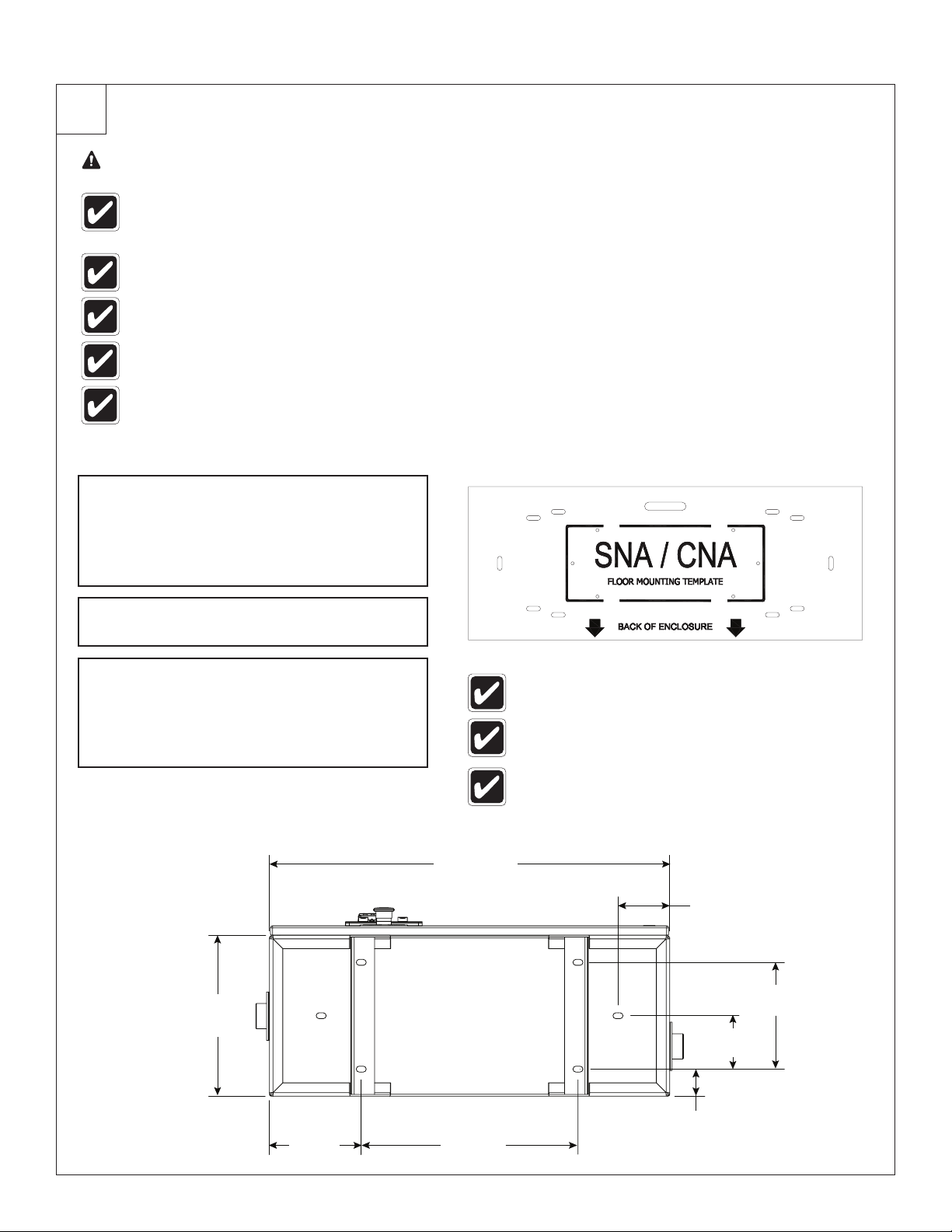
Set the heater in a vertical, upright
position with the water outlet located
at top. Use the floor mounting template
A
from the inside of the crate to help with
alignment of the leg mounting.
Secure heater by bolting each leg to the
B
floor using 3/8" (10mm) anchor bolts.
Install the pressure and temperature relief
valve on hot water outlet immediately
following the union.
C
NOTICE! Valve must empty into a
drain.
3/4" x 7/16"
(20mm x 10mm)
Slot
(6) Places
12"
(305mm)
Rectangle outline on template is not actual size of
heater.
Template may require cutting to fit into tight areas.
Holes are for alignment purposes and may not
represent actual drill size for mounting hardware.
30" (762mm)
3-7/8"
(99mm)
8"
(204mm)
4"
(102mm)
2"
6-7/8"
(175mm)
6
6/10/2016 Bradley • 215-1815 Rev. E; ECN 16-17-016
16-1/4"
(413mm)
(51mm)
Installation SNA-Series Tankless Heater
2
Plumbing Installation
Components Needed:
• (6) Union 1-1/4"
• Shutoff Valve
• Pressure and Temperature Relief Valve (150 psi/10 bar)
• Y-Strainer (100 mesh) or Inline Filter (150 microns)
• (2) Gate or Ball Type Valves
• Drain pipe
• Water hammer arrestor (recommended)
• Elbows, nipples and fittings as needed
CAUTION To avoid damage to the electronics
or internal wiring, do not perform
any brazing or sweat soldering
inside the enclosure.
NOTICE! Failure to install proper filtration may
result in a flow sensor malfunction.
NOTICE! To avoid water damage, install a drain
pipe from the pressure relief valve to an
unrestricted drain.
If end use fixture is not at the highest point in
the plumbing loop, then an automatic air vent
valve must be added at the highest point in the
system or at any drop to eliminate trapped air.
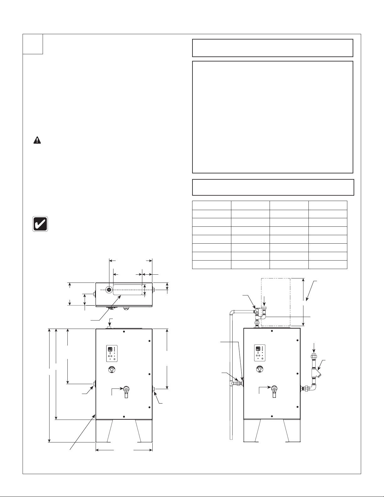
Dimensions,
Plumbing
and Electrical
Configurations
12"
(305mm)
Access Panel
29"
(737mm)
B
A
6" (152mm)
23-1/2" (597mm)
15-1/4"
(387mm)
5-1/2" (140mm)
1-1/4" Female NPT
Outlet
6" (152mm)
3-3/4"
(95mm)
31-1/2"
(800mm)
Install shutoff valve above (upstream of)
A
the heater inlet.
Install one union on the water inlet side of the
heater and another union upstream of the 100
Mesh (150 micron) y-strainer.
Install one union on the water outlet side of the
heater and another after the P & T Relief Valve.
Install one union on the TepidGuard™ discharge outlet.
B
Install the pressure relief valve (150 psi/10 bar)
and outlet plumbing of heater per code
requirements and route relief valve discharge to
drain. Make sure no shutoff valve is between the
water heater outlet and the relief valve, as well as
no shutoff valve between the relief valve discharge
and drain. Ensure plumbing is secure and not
subject to vibrations.
Use 1-1/4" hard copper tubing or pipe as needed.
C
Dim. “A” Dim. “B” Dim. “C”
36kW
54kW
63kW
72kW
108kW
126kW
144kW
“TepidGuard
Discharge
(Drain)
Threaded
Union
™
60"(1524) 48"(1219) 36"(914)
60"(1524) 48"(1219) 36"(914)
72"(1829) 60"(1524) 48"(1219)
60"(1524) 48"(1219) 36"(914)
60"(1524) 48"(1219) 36"(914)
72"(1829) 60"(1524) 48"(1219)
72"(1829) 60"(1524) 48"(1219)
Relief
Valve
”
Outlet
“C” to be clear of
C
Rotate outlet 90°
during installation
for adequate
Inlet
Maintain area
above Access
Panel for height
obstructions
clearance
“Y” Strainer
1-1/4" NPT
Female
“TepidGuard
Discharge
(Drain)
Suggested Location For
Power Entrance. Holes
Provided By Installer.
™
”
Optional
Fused
Disconnect
30"
(762mm)
1-1/4" NPT
Female
Inlet
To Drain
Components provided by installer unless otherwise specified.
Reference the product options sections or contact your local Bradley
Suggested Installation Configuration
Optional
Disconnect
Representative for product options.
Bradley • 215-1815 Rev. E; ECN 16-17-016 6/10/2016
Fused
7
SNA-Series Tankless Heater Installation
3
Electric Installation
WARNING All Keltech heaters must be fused
in accordance with National
Electric Code (NEC) for the full
load amperage listed on the
nameplate rating for each heater.
WARNING Failure to properly ground the unit(s)
per the National Electric Code could
result in injury or death.
Open enclosure door.
A
NOTICE! Any option that requires field wiring
must be done with 600V cable per
the schematic that was shipped with
the heater.
NOTICE! Use a 4-core cable or multi-stranded
machine tool wire from an approved
isolating 3-pole switch or circuit
breaker.
NOTICE! Make sure the electrical cable is the
correct size to carry 100% of the full
load current. See table for proper
wire sizes.
Using a hole punch, cut a hole the proper
size for conduit connection; large enough
for the wire size for each heater. The
B
connectors need to be rated NEMA4/4X
to ensure proper sealing of the enclosure.
Run wires through the appropriate size
C
conduit.
Connect wires to the system terminal
block or fused disconnect inside the
D
enclosure.
Connect the ground wire to the stud
E
provided with the “Ground” label beneath it.
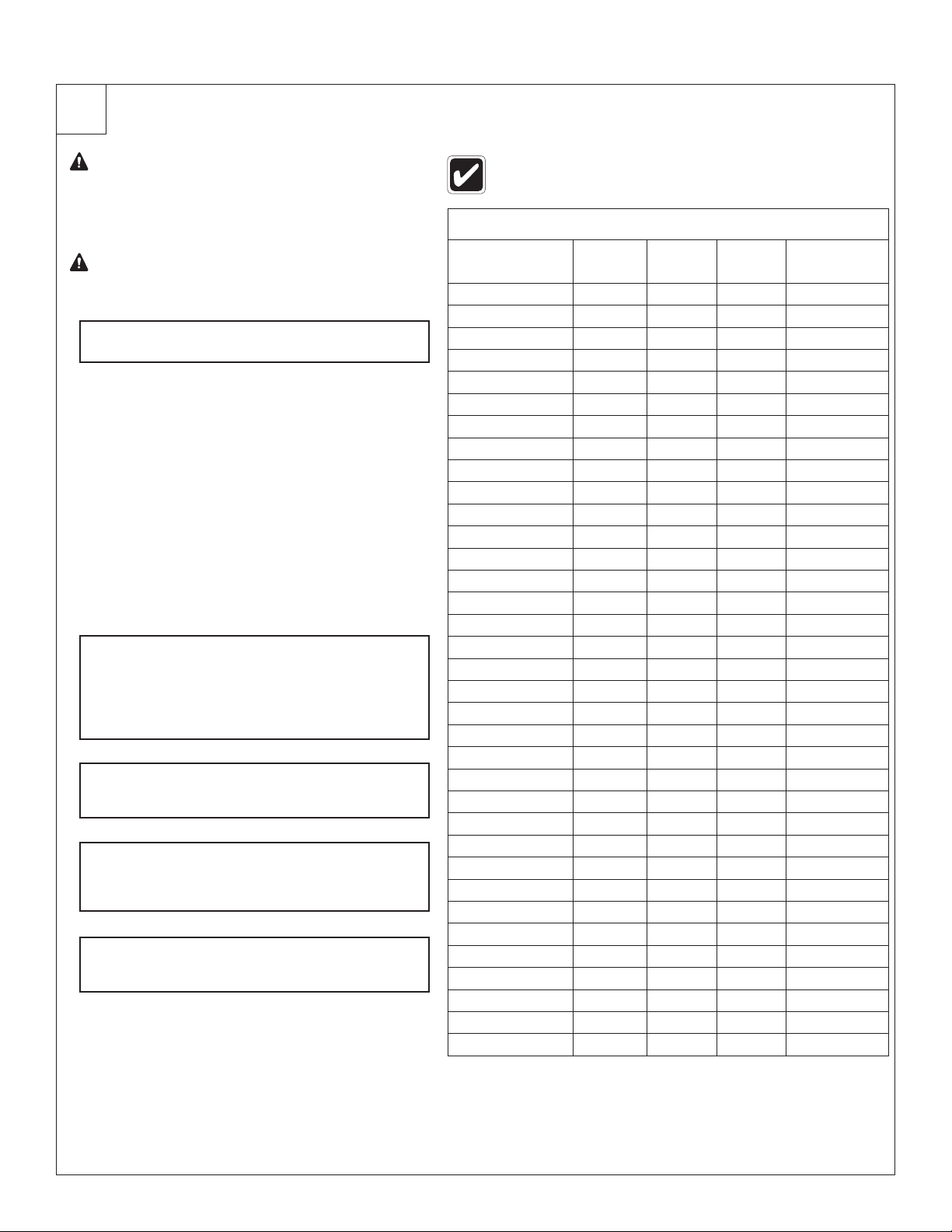
Not all available (optional) voltages are listed
in the table.
SNA & SNAR ELECTRICAL SPECIFICATIONS FOR HEATER**
Model Voltage Amps kWatts
SNA-363/600D 600 35 36 8 AWG*
SNA-543/600D 600 52 54 6 AWG*
SNA-633/600D 600 61 63 4 AWG*
SNA-723/600D 600 69 72 4 AWG*
SNA-1083/600D 600 104 108 2 AWG*
SNA-1263/600D 600 121 126 1 AWG*
SNA-1443/600D 600 139 144 1/0 AWG*
SNA-363/480D 480 43 36 6 AWG*
SNA-543/480D 480 65 54 4 AWG*
SNA-633/480D 480 76 63 4 AWG*
SNA-723/480D 480 87 72 3 AWG*
SNA-1083/480D 480 130 108 1 AWG*
SNA-1263/480D 480 152 126 1/0 AWG*
SNA-1443/480D 480 174 144 2/0 AWG*
SNA-363/415D 415 38 27 8 AWG*
SNA-543/415D 415 56 40 6 AWG*
SNA-633/415D 415 65 47 4 AWG*
SNA-723/415D 415 75 54 4 AWG*
SNA-1083/415D 415 113 81 2 AWG*
SNA-1263/415D 415 131 94 1 AWG*
SNA-1443/415D 415 150 108 1/0 AWG*
SNA-363/400D 400 36 25 8 AWG*
SNA-543/400D 400 53 37 6 AWG*
SNA-633/400D 400 64 44 4 AWG*
SNA-723/400D 400 72 50 4 AWG*
SNA-1083/400D 400 108 75 2 AWG*
SNA-1263/400D 400 126 87 1 AWG*
SNA-1443/400D 400 144 100 1/0 AWG*
SNA-363/380D 380 35 23 8 AWG*
SNA-543/380D 380 50 33 6 AWG*
SNA-633/380D 380 59 39 6 AWG*
SNA-723/380D 380 68 45 4 AWG*
SNA-1083/380D 380 103 68 2 AWG*
SNA-1263/380D 380 120 79 1 AWG*
SNA-1443/380D 380 137 90 1/0 AWG*
* Based on the NEC Table 310.15 for 75°C insulated copper wire @ 30°C
Ambient. Aluminum wire requires larger gauges.
** SNAR (reverse models) electrical specifications are same as SNA heater
models.
Min Wire
Size
8
6/10/2016 Bradley • 215-1815 Rev. E; ECN 16-17-016

Installation SNA-Series Tankless Heater
4
Start Up Check List
Plumbing
System is set in a vertical, level, and upright position with the outlet located at the top. System is mounted by
legs (2) bolted to the floor (3/8" dia. minimum).
Confirm installation of shutoff valve above (upstream of) the union on the inlet connection. Confirm installation of
a Y-strainer (100 mesh screen) or inline filter (150 micron) between the inlet shutoff valve and the heater.
Pressure and temperature relief valve is installed on tepid water outlet immediately following the union. No valve
or restriction is between the relief valve and the system or the relief valve and drain. Shutoff valve is installed
after pressure and temperature relief valve on outlet if required by local or national plumbing codes.
If the hot water process is not at the highest point in the plumbing loop, then an automatic air vent valve must be
added at the highest point in the system plumbing loop to eliminate trapped air.
Electrical
Verify supply voltage matches the indicated voltage on the Serial Tag. Serial Tag is located within the heater
enclosure on the upper right corner of the back plate (mounting plate). Voltage can also be verified on the name
plate on the door of the heater.
Appropriate conduit is installed properly, secured and sealed to unit enclosure per NEC and hazard
location requirements.
Appropriate conductors for unit routed through conduit and secured to power block inside the enclosure. All
electrical is installed in accordance with national and local electrical codes, including fuse size and rating.
Appropriate earth ground is installed to the lug provided on enclosure backplate.
Bradley • 215-1815 Rev. E; ECN 16-17-016 6/10/2016
9
SNA-Series Tankless Heater Installation
5
Start Up
WARNING Make sure the circuit breaker for the heater is OFF.
Be sure that plumbing and electrical are complete per Start Up Check List.
Slowly turn on water supply to the unit
A
with the enclosure door open and the
circuit breaker in the off position.
Slowly turn on the water outlet valve,
activate the connected process requiring
heated water (faucet, shower, etc.), then
flush the system for 5 minutes to ensure all
B
air is purged from the system.
NOTICE! Failure to bleed air properly
will damage elements and
cause heater malfunction.
Turn off the connected process and
check the entire system to verify leak-free
C
installation.
Close enclosure door and secure.
D
Depress the Emergency Stop Button.
Energize the electrical service to the unit
F
by switching on the circuit breaker.
Pull out Emergency Stop Button.
G
After a six second discharge from the
TepidGuard overshoot purge system, the
unit is now in the ready-state.
Turn on the connected process; observe
H
output temperature rise to setpoint.
Top portion of temperature controller
displays output temperature, bottom
displays setpoint temperature (setpoint
temp is not adjustable on SNA Models).
When startup is complete, leave circuit
breaker in the ON position and the
Emergency Stop Button on the door
I
pulled out. The Green power light should
be illuminated.
If your heater has the EXP2CFPM
E
option and is located in a Class I
Division 2 area, please review Special
Installation & Operation Instructions
section for all proper electrical
connections and sealing to ensure
the installation will provide proper
protection. Proceed to Step F once you
have completed the steps in the Special
Installation & Operation Instructions or if
you do not have this option.
NOTICE! If your heater is mounted in an area
where freezing temperatures are possible,
an ENHT Freeze Protection Option is
strongly recommended and the heater
must be powered at all times to be
Freeze Protected. If continuous power is
not possible, do not allow the heater to
remain full of water. Freezing of the heater
can cause serious damage.
10
6/10/2016 Bradley • 215-1815 Rev. E; ECN 16-17-016
Installation SNA-Series Tankless Heater
6
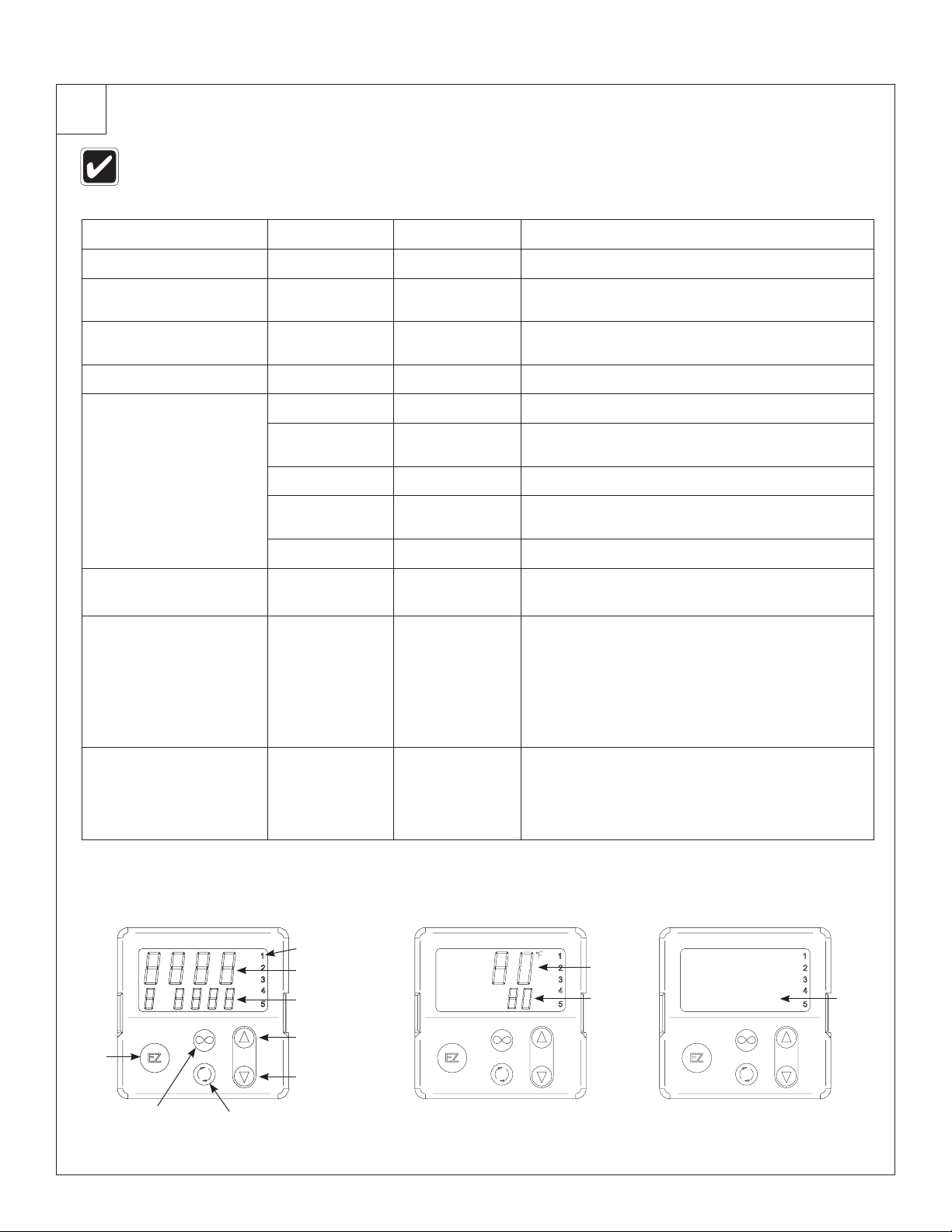
Digital Controller Operation
The preprogrammed digital controller is mounted through the bezel on the enclosure door. The digital
controller will not be powered until water is flowing through the heater. The bottom display will then display
the setpoint temperature (See Digital Controller Operation section for more information).
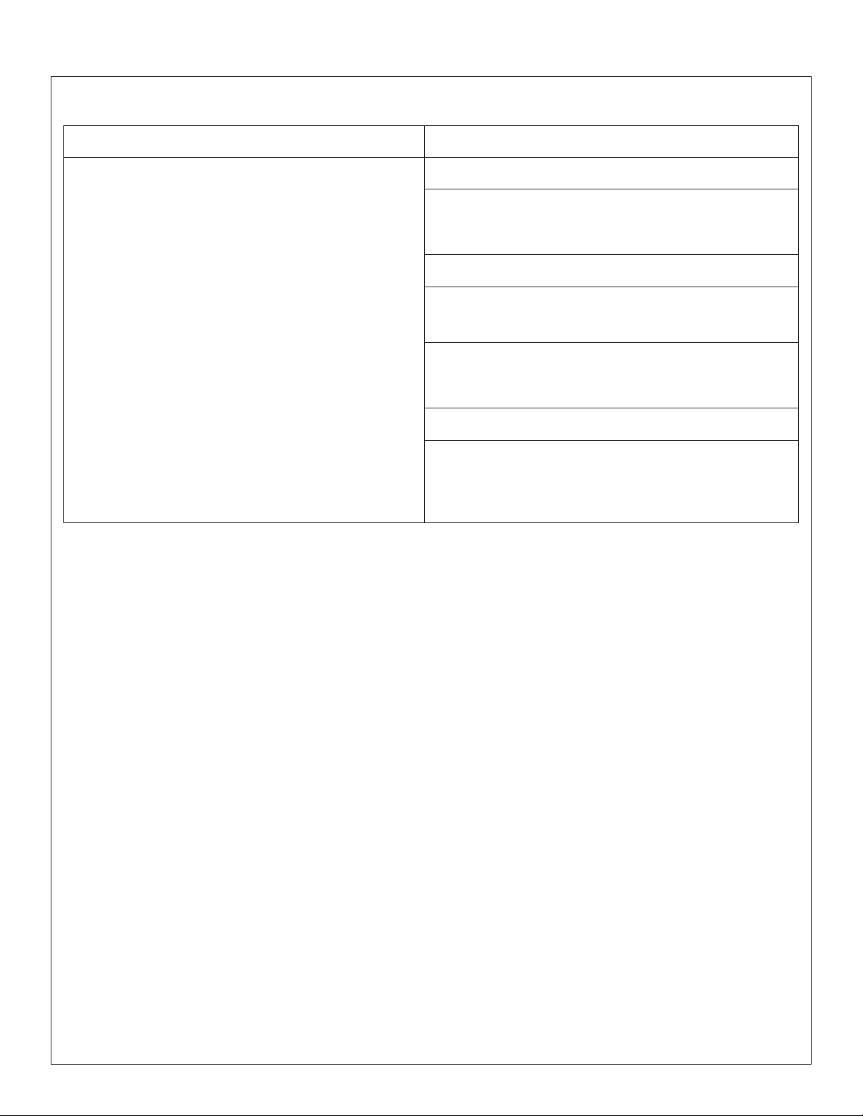
Description Upper Display Lower Display Function
EZ Key Toggles output on/off (Disabled on SNA Models)
Setpoint Up Button Increases output temperature (Disabled on SNA
Models)
Setpoint Down Button Decreases output temperature (Disabled on
SNA Models)
Infinity Key Back to Home page
Advance Key Advances through parameter prompts
Auto, Man, Off C.r71 Turns Control Loop On/Manual/Off (Disabled on
SNA Models)
XX.X% h.Pr1 Heater Power % (Disabled on SNA Models)
no AUt1 Autotune (Contact Factory) (Disabled on SNA
Models)
C or F C_F1 Change Temperature Units from F to C
Output Indicators (1-5) Output 1,2,3,4 or 5 are active and operating if
these LEDs are illuminated.
Setpoint Temperature
(Lower Display)
Output Temperature
(Upper Display)
In Red Displays:
In Green Displays:
• Setpoint
• Percent Power
• Temperature units F or C
• Menu prompt name
• Alarm code
• Actual process temp. of outgoing water
• Prompt parameter value
• Error code (feature disabled)
Layout Diagram ON - Heating OFF - No Flow
Output Indicators
1
2
Output Temp.
3
4
Setpoint Temp.
5
1
2
3
4
5
Output
Temp.
Setpoint
Temp.
1
2
3
4
Blank
5
Setpoint Up
EZ Key
Setpoint Down
Advance KeyInfinity Key
Bradley • 215-1815 Rev. E; ECN 16-17-016 6/10/2016
11
SNA-Series Tankless Heater Installation
7
Perform Operational Test No. 1
Ensure the enclosure door is closed prior to
performing operation test.
Set the 3-pole switch or circuit breaker to the
A
ON Position.
Pull out the Emergency Stop Button. Heater
will automatically perform a 6 second
B
discharge from the TepidGuard overshoot
purge system. Wait for purge cycle to complete.
When flow rate reaches approximately 1.5gpm
(5.7lpm), the flow sensor recognizes this
condition and begins the heating process.
When the flow sensor activates:
• Green bank energized lights illuminate on the
front bezel verifying power supply connection to
C
the heating elements via the solid-state relays.
• Element load lights may be solid or flash
in unison as heating elements modulate
depending on the hot water demand.
• Digital temperature controller shows water
temperature. Additional programming is
not necessary.
Heaters installed in pump-and-well supplied
water systems may require an operating
pressure adjustment to a differential pressure
of approximately 10 psi. For example, if the
high limit pressure is 40 psi, adjust the low
limit pressure to 30 psi with the pressure
switch located on the supply pump.
Located on the panel are one (36-63kW)
or two (72kW-144kW) green ready lights.
When illuminated, the safety circuit is
engaged and ready for use.
Test water temperature and stability at
outlet by viewing the display. Controller
D
displays (in red) the temperature of water
exiting the heater.
Heater will not energize heating elements if the
inlet water temperature is equal to or greater than
the temperature set on the digital controller.
Deactivate the shower or eyewash. The
flow sensor will electrically open contacts
and remove power from the elements and
E
controller so that the display is blank and
bank lights are off. Power light stays on.
If the water flow exceeds maximum heating capacity of the heater, the temperature of water at the
outlet may be lower than the temperature selected on the controller. See below to determine maximum
temperature rise capabilities.
12
6/10/2016 Bradley • 215-1815 Rev. E; ECN 16-17-016
Installation SNA-Series Tankless Heater
8
Perform Operational Test No. 2
Each model has precise specifications for temperature rise capabilities.
Turn on hot water faucet/fixture/process
(min flow rate of 1.5gpm/5.7 lpm). The heater
A
should activate immediately.
Turn off hot water faucet/fixture/process.
The flow sensor will deactivate and shut
B
off power to the heater.
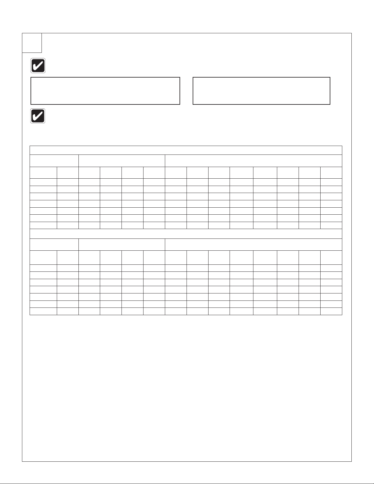
If the water flow exceeds maximum heating capacity of the heater, the temperature of water at the outlet
may be lower than the temperature selected on the controller. See table below to determine maximum
temperature rise capabilities.
SNA-Series
Maximum Temperature Rise (GPM & °F)
Low Flow Activation (eyewash)
Models
480/600V
SNA-363 12/36 33 27 16 10 16 12 10
SNA-543 18/54 49 41 25 15 25 18 15 12 10
SNA-633 24/63 57 57 29 20 29 22 17 15 12
SNA-723 27/72 73 61 37 23 32 24 19 16 14 10
SNA-1083 40/108 109 90 54 34 49 36 29 24 21 18 16 14
SNA-1263 47/126 128 106 64 40 57 43 34 28 24 21 19 17
SNA-1443 54/144 147 122 73 46 65 49 39 33 28 24 21 19
kW Low/
High
2.5 gpm
ΔT °F
(1.5 gpm)
3 gpm
ΔT °F
5 gpm
ΔT °F
8 gpm
ΔT °F
15gpm
ΔT °F
Maximum Temperature Rise (LPM & °C)
Low Flow Activation (eyewash)
(5.7 lpm)
Models
480/600V
SNA-363 12/36 18 15 9 6 9 7 6
SNA-543 18/54 27 23 10 8 14 10 8 7 6
SNA-633 24/63 32 32 16 11 16 12 9 8 7
SNA-723 27/72 40 34 21 13 18 13 11 9 8 6
SNA-1083 40/108 60 50 30 19 27 20 16 13 12 10 9 8
SNA-1263 47/126 71 59 36 22 32 24 19 16 13 21 11 9
SNA-1443 54/144 82 68 41 26 36 27 22 18 16 13 21 11
kW Low/
High
9.5 lpm
ΔT °C
11.3 lpm
ΔT °C
18.9 lpm
ΔT °C
30.3 lpm
ΔT °C
56.7 lpm
ΔT °C
High Flow Activation (drench shower) (15 gpm)
20gpm
ΔT °F
75.6 lpm
ΔT °C
25 gpm
ΔT °F
High Flow Activation (drench shower) (56.8 lpm)
94.5 lpm
ΔT °C
30gpm
ΔT °F
113.4 lpm
ΔT °C
35gpm
ΔT °F
132.5 lpm
ΔT °C
40 gpm
ΔT °F
151 lpm
ΔT °C
…continued on next page
45gpm
ΔT °F
170.3lpm
ΔT °C
50gpm
ΔT °F
189.3lpm
ΔT °C
Bradley • 215-1815 Rev. E; ECN 16-17-016 6/10/2016
13

SNA-Series Tankless Heater Installation
SNA-SKID Series System (includes SNA and reverse configuration SNAR)
Maximum Temperature Rise (GPM & °F)
Low Flow Activation (3 gpm) High Flow Activation (30 gpm)
Models
480/600V
SNA &
SNAR-1083
(108 kW each)
SNA &
SNAR-1263
(126 kW each)
SNA &
SNAR-1443
(144 kW each)
Models
480/600V
SNA &
SNAR-1083
(108 kW each)
SNA &
SNAR-1263
(126 kW each)
SNA &
SNAR-1443
(144 kW each)
Total kW
Low/High
80/216 109 90 54 34 49 36 29 24 21 18 16 14
94/252 128 106 65 40 57 43 34 28 24 21 19 17
108/288 147 122 79 46 65 49 39 33 28 24 21 19
5 gpm
ΔT °F
6 gpm
ΔT °F
10 gpm
ΔT °F
16 gpm
ΔT °F
30 gpm
ΔT °F
40 gpm
ΔT °F
50 gpm
ΔT °F
60 gpm
ΔT °F
70 gpm
ΔT °F
80 gpm
ΔT °F
90 gpm
ΔT °F
100 gpm
ΔT °F
Maximum Temperature Rise (LPM & °C)
Low Flow Activation (11.4 lpm) High Flow Activation (113.6 lpm)
113.6
lpm
151.4
lpm
189.3
lpm
227.1
lpm
265
lpm
302.8
lpm
340.7
lpm
Total kW
Low/High
80/216 60 50 30 19 27 20 16 13 12 10 9 8
94/252 71 59 36 22 32 24 19 16 13 21 11 9
108/288 82 68 41 26 36 27 22 18 16 13 21 11
18.9 lpm
ΔT °C
22.7 lpm
ΔT °C
37.9 lpm
ΔT °C
60.6 lpm
ΔT °C
ΔT °C
ΔT °C
ΔT °C
ΔT °C
ΔT °C
ΔT °C
ΔT °C
378.5
ΔT °C
lpm
Output heating capacity is reduced if these heaters are installed on 415V, 400V or 380V 3-ph.
Contact the factory to supply this information. Satisfactory performance of the heater is dependent upon a specific
flow rate vs temperature rise capability. If the desired temperature is not achieved, please verify the following:
1. Circuit breaker is on and rated for the maximum power draw.
2. Heater is drawing the proper current for the supply voltage on all 3 phases.
3. All 3 phase indicator lights are lit (not flashing) indicating maximum power draw and maximum
amperage is being drawn.
4. Flow rate and temperature rise requirements are compatible with the heater specifications.
5. Verify there is no additional supply of cold water entering the line downstream of the heater.
14
6/10/2016 Bradley • 215-1815 Rev. E; ECN 16-17-016

Installation SNA-Series Tankless Heater
TepidGuard™ Flow Conditions
When a low flow condition (less than 15 gpm/56.8 lpm) occurs, such as operation of the eye/facewash, individual
elements are energized to supply water for the eye/facewash and/or drench hose. One set of PID values is selected
on the controller for accurate temperature control at low flow conditions.
When the heater detects high flow conditions (greater than 15 gpm/56.8 lpm), all elements are energized. A second
set of PID values is selected on the controller for accurate temperature control at high flow conditions.
When the heater shuts down or switches from high to a low flow condition, the purge valve opens and purges the
heater of latent (excess) heat. This anti-scald feature works both actively at the end of each shower or passively if
sitting in an environment that may exceed 95°F (35°C). This TepidGuard™ system ensures safe water temperatures
at both the eyewash and shower stations.
Product Options
AL3 & AL3-SL Temperature Alarms: The AL3 option provides dry contacts that open to signal flow >1.5 gpm
(5.7lpm) has activated the heater. The AL3-SL option provides these dry contacts and additionally activates a local
audible and visual alarm on the heater.
GF (Ground Fault): Detects electrical leakage from external sources to protect equipment, electronics, and the heat
exchanger from being damaged in the event of a power fault. After turning on water, then power, test ground fault:
1. Press GF Test button.
2. Watch for ground fault light to illuminate and Bank Ready light(s) to shut off. The Ground Fault system is active
and in working order.
3. Press the GF Reset button, hold for 2 seconds and release to reset ground fault.
NOTE: If a trip occurs under normal operation DO NOT RESET Ground Fault without evaluation and service.
NOTE: Normal state is Ground Fault light OFF, Bank Ready lights ON.
ENHT Freeze Protection (ENHT & ENHT30): ENHT offers protection to -20°F (-28°C). The ENHT30 offers protection to
-30°F (-34°C). Each level of protection utilizes the normal heater supply voltage. No additional dedicated circuit to the unit
is required during field installation. Freeze protection (ENHT option) includes an internally insulated NEMA 4/4X enclosure
and thermostatically controlled forced air heater to maintain internal temperatures above freezing. ENHT options also
include a connection point for DCS monitoring. In the event of a power interruption or ENHT system failure when internal
enclosure temperatures reach 40°F (4°C) or lower, the unit will notify a facilities control/monitoring system that the unit is
unable to maintain freeze protection. Regardless of state of power to the unit, this warning notifies maintenance personnel
and provides an opportunity to correct the condition before any damage occurs to the unit.
NOTICE! With this option, three phase power must be continuously applied to the heater for the internal
freeze protection heater to operate properly and provide protection. If three phase power cannot
be continuously applied, the heat exchanger must be completely drained of water and electrically
locked out or damage from freezing may occur. Use Start Up procedure to restart this equipment.
This option does not require a separate electrical circuit.
NOTICE! Failure to maintain power at all times may result in damage to the heater and void the warranty.
Please utilize the temperature sensor contacts (N.O.) that can provide a signal to a remote device,
DCS monitoring or BMS (Building Management System) signal. When temperature inside the
cabinet drops below 40°F (4°C) operation of the system should be verified.
EXP2CFPM (Continuous Flow Explosion Proof Purge System): Keltech’s EXP2CFPM option makes heaters
compliant for classified areas: Class I Division 2, Groups A, B, C, D, Temp Code: T5. The Purge System requires a
supply of clean instrument air or inert gas (provided by installer). This supply maintains a positive internal pressure
and prevents the enclosure from filling with flammable gasses, dusts or vapors from the ambient environment.
Complete installation provided in this manual.
FDS Fused Disconnect: Internal fused disconnect interlocks with enclosure door when energized, prohibiting access
to a live cabinet. Select the FDS option for an additional level of safety and convenience at the heater location.
HLW (ASME Certified Heat Exchanger): Available on SNA-63 and larger. The heat Exchanger is made of special
brass and certified by ASME inspector for quality of workmanship.
N4X (NEMA 4X): Corrosion resistant enclosure made of stainless steel and ideal for harsh environments.
Bradley • 215-1815 Rev. E; ECN 16-17-016 6/10/2016
15

SNA-Series Tankless Heater Installation
Maintenance
Preventative maintenance is important for optimal performance of the heater. To ensure the heater works properly,
always keep the inside of the enclosure dry. Moisture inside an enclosure increases the humidity, which condenses
on cooler surfaces. This can cause electrical problems and reduce the efficiency of enclosure insulation. To prevent
problems perform the following:
• Verify the interior of the enclosure is dry.
• Verify there are no leaks in seals of enclosure and that in high humidity environments all enclosure egresses are
properly sealed.
• Ensure plugs are in place on back side of enclosure.
• Monitor Shower heater performance at each routine safety shower inspection.
• Verify the following lights illuminate with activation of the Shower or Eye/FaceWash:
• Green bank energized lights
• Digital display controller
• Red element load lights 1-4
• Green power light illuminated
• Verify that the heater activates the “TepidGuard” discharge port by purging water whenever the shower is deactivated. If
heater does not perform as expected, take appropriate corrective action by evaluating the cause and repair as necessary.
• Check seals monthly during temperatures above 32°F (0°C) and weekly during temperatures below 32°F(0°C).
Check internal freeze protection system(ENHT, ENHT30) prior to first seasonal freeze for proper performance. The
external heater and internal thermostat are factory set at 55°F(13°C). Check weekly during temperatures below
32°F (0°C). See Information in Product Options section for additional information on freeze protection.
• Bimetal manual reset safeties mounted to the heat exchangers may trip at temperatures below 32°F (0°C) on
heaters equipped with ENHT or ENHT30. The bimetal manual resets are set to trip at 100°F (38°C). Heat trace
installed on connected piping can heat water to temperatures above 100°F (38°C), causing the manual reset
safeties to trip. Reset bimetal manual safeties and lower heat trace temperature to below 100°F (38°C).
• All heaters require filtration of 150 microns or smaller to ensure proper operation. Y-strainers or additional filtration
should be verified and cleaned at least every 6 months or more often in areas where hard water sediment is
present in the water.
To clean the Y-Strainer:
1. Turn the power off at the circuit breaker panel.
2. Shut off the installer supplied cold water isolation valve to the heater.
3. Relieve pressure in the plumbing lines.
4. Position a bucket under the cold water inlet to catch any water that may still be in the pipe.
5. Loosen the plumbing connection on the Y-strainer to get to the screen.
6. Remove screen and clean out debris. Use a wire brush to clean smaller particles from the screen.
7. Once the screen is clean, put it back into the Y-strainer housing and secure the plumbing connection.
8. Before switching the power back on, bleed the air out of the lines by turning heater water supply back on and
the plumbing fixture or process farthest from the heater.
9. With the air purged, turn on all circuit breakers supplying the water heater.
• At the same time the Y-strainer or additional filtration is cleaned, it is a good practice to also check all valves
connected to the system. With no water flow through the heater, work both the inlet ball valves and the outlet gate
valves open and shut to break up any calcium deposits that may have formed from the valve being open for an
extended period of time. Power to the heater does not need to be turned off to do this.
16
6/10/2016 Bradley • 215-1815 Rev. E; ECN 16-17-016
Installation SNA-Series Tankless Heater
Troubleshooting for Controller
Problem Solution
No Power Verify power is on.
Turn off power. Check continuity of all internal fuses in
control transformer, heating elements or optional Fused
Disconnect circuits.
Check all field service circuit breakers or fuses.
Check the safety interlock door switch to make sure
that lack of power is not due to misadjustment or open
enclosure door.
Check system temperature limit control to make sure
it has not activated due to excessive heat exchanger
temperature or faulty sensor.
Turn off power. Check for loose or disconnected wires.
Check the incoming service connection. Voltage must
match name plate rated voltage. Labels are located on
the cabinet door and on upper left of back plate (Serial
Number Label).
Bradley • 215-1815 Rev. E; ECN 16-17-016 6/10/2016
17

SNA-Series Tankless Heater Installation
Troubleshooting using the Flow Limit Control Board (FLCB)
Problem Solution
The heater does not work or works intermittently.
High Temp.
Limit Sensor
Input
High Flow
Status
Low Flow
Status
Bank 2 Over
Temp. (OT)
Bank 1 Over
Temp. (OT)
Purge/Dump
(SNA Models
Only)
Check that the flow sensor located at the inlet is spinning
with water running. Check if in Low flow (> 1.5gpm/5.7lpm)
that the FLCB light is on. If in High flow (> 15gpm/56.8lpm)
both the low flow light and high flow lights will be
illuminated.
Check that water flow through the heater is adequate to
activate the flow sensor at 1.5gpm (5.7lpm).
Check that the heater is wired with the proper breaker and
wire size. Refer to Electrical Specifications table for proper
requirements.
Check that the unit is receiving voltage from all 3 phases
of the power source. A load voltage reading is also helpful.
Element Load Bank 1–2 or 3–4 is not energized. Check FLCB with corresponding light indicated:
Bank 1–2 on the front bezel = Bank 1 on the FLCB
Bank 3–4 on the front bezel = Bank 2 on the FLCB.
If the light is off and there is power on. Check if water
temperature is greater than 175˚F (79°C). Decrease water
temperatures and restart.
If the above steps do not solve the problem, some additional checks may be performed. Follow the
schematic to perform the following continuity checks:
Emergency stop switch.
Door guard.
High temperature bimetals (Manual Reset Safeties).
Optional ground fault breaker must be in the closed position for the unit to work.
All internal breakers must be in the ON position for the unit to work.
For additional information on Troubleshooting or other information, please call Keltech Inc. technical support at
1-800-999-4320. Please have Model No. and Serial No. available when seeking technical assistance. Serial No.
tag is located in the enclosure on the upper left hand corner of the back plate. Please record and maintain this
information at all times:
SNA- Model No.
Serial No.
18
6/10/2016 Bradley • 215-1815 Rev. E; ECN 16-17-016
Installation SNA-Series Tankless Heater
Special Installation and Operating Instructions
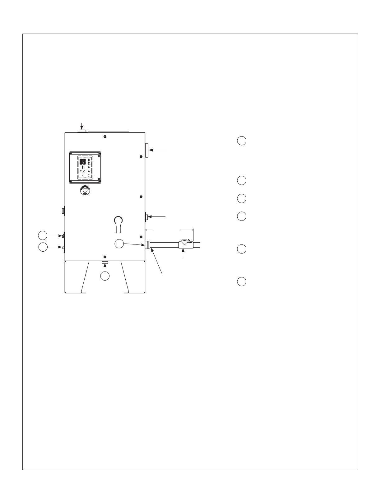
Tankless Water Heaters With Optional Class I Division 2 Purge EXP2CFPM Option
General Information
All Keltech Tankless Water Heaters with a model number suffix of – EXP2CFPM have been fitted with a Z purge
system to pressurize the enclosure suitable for use in Class I Division 2 Hazardous Locations.
A Continuous Flow (Model CF) Mini-Z Pressurizing System has been fitted to the inside of the enclosure.
Outlet
1
Suggested region for power
Purge System
Relief Valve
Inlet
18"
3
6
1
5
(458mm)
Max
Explosion proof
sealing fitting
supplied by others
Conduit Hub
Class 1 Div. 2
supplied by others
entrance at right/bottom of
enclosure. Entrance hole and
components to be provided by
installer.
2
All plumbing fittings are 1-1/4" NPT
female threaded.
3
Purge Control Panel
Class 1 Division 2
4
All installation egress from
panel must be sealed (electrical
conduit) for proper explosion proof
installation.
5
Spark arrestor with calibration
orifice is located in the bottom of the
enclosure.
Purge gas/compressed air inlet
6
fitting here.
EXP2CFPM Installation Notes
1. Any tubing, conduit or fittings connected to the Pressurized Enclosure (PE) must conform to local codes for
flammability ratings.
2. All egress into PE must be plugged and properly sealed to minimize leakage of purge air. Use hazardous
location sealing fittings suitable for Class I locations within 18" (458mm) of enclosure.
3. The EXP2CFPM purge system option is a continuous flow purge system mounted inside the cabinet enclosure
and calibrated to flow at 0.9 SCFM (1.5291 CMH). To minimize waste, plug and seal all openings and conduit.
4. The system is designed for use primarily with compressed air. The source of the compressed air must be
from a non-classified area (see Purge Gas Supply Notes). Purge air must be clean, dry and free of flammable
gases. When inert compressed gases are used (Nitrogen, for example) the installer and facility manager must
take suitable precautions on-site so that buildup of the inert gas does not present a health hazard. Where risk
of asphyxiation exists, a warning label must be fitted to the Pressurized Enclosure (PE).
5. Adjustment of Purge System is not necessary. System is fully calibrated.
6. Connect to Purge System where indicated above. Connection port is 1/4" NPT female. Supply pressure must be
regulated to 60–115 PSI (4-8 bar).
Bradley • 215-1815 Rev. E; ECN 16-17-016 6/10/2016
19
 Loading...