

Bradley S19-690, S19-690LHS Installation Manual
SA
U
51-5817)
-2
2
: (26
X
WI 53052-0309
,
FA
m
o
Y
09
FALLS
3
LE
rp.c
OX
o
NEE
AD
B
R
O
P.O.
NOM
800-B
bradleyc
.
ME
EL: 1
/www
/
T
http:
P.O. BOX 309
MENOMONEE FALLS, WI 53052-0309 USA
TEL: 1-800-BRADLEY FAX: (262-251-5817)
http://www.bradleycorp.com
S19-690LHS
S19-690
Installation
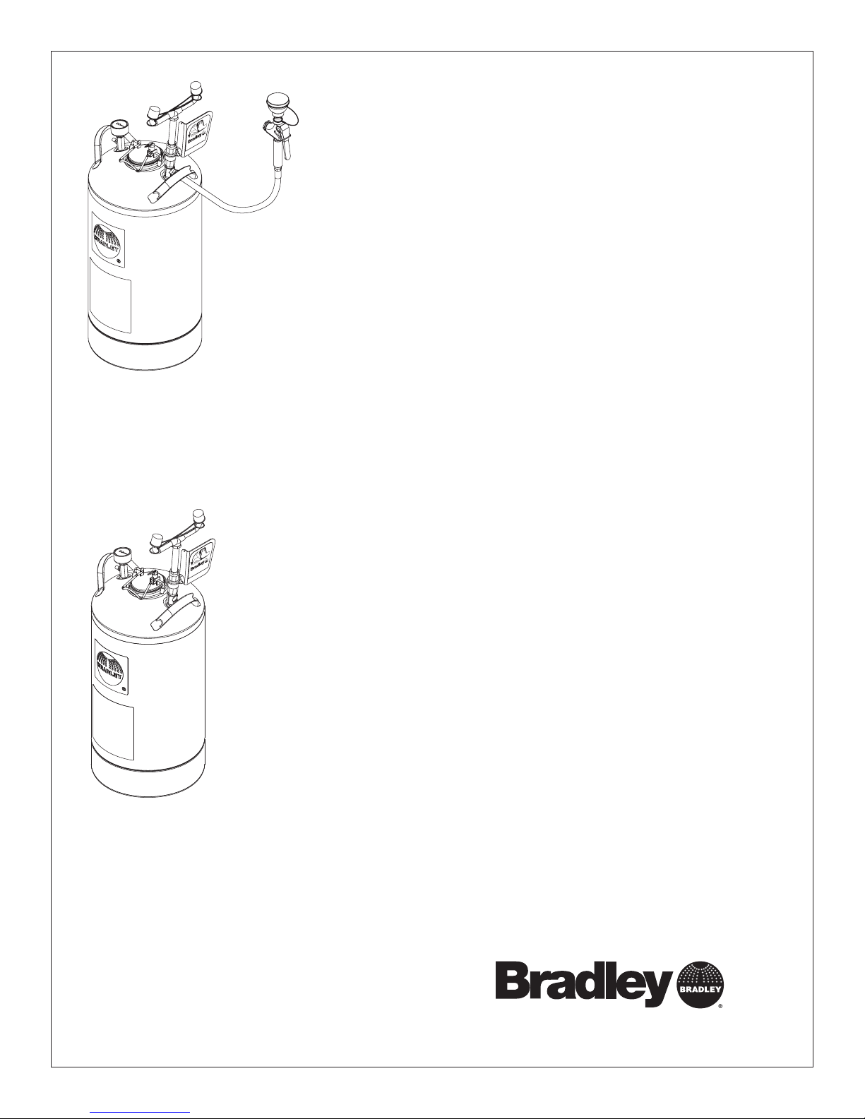
S19-690
10-Gallon Tank with Eyewash and Hose Spray
Réservoir de 10 gallons avec douche oculaire
et douchette
Depósito de 10 galones con lavaojos y
manguera de aspersión
S19-690LHS
10-Gallon Tank with Eyewash
Réservoir de 10 gallons avec douche oculaire
Depósito de 10 galones con lavaojos
Table of Contents
Pre-Installation Information . . . . . . . . . . . . . . . . . . . . . . 2
S19-690 Installation . . . . . . . . . . . . . . . . . . . . . . . . . . . . 3
S19-690LHS Installation . . . . . . . . . . . . . . . . . . . . . . . . 4
Maintenance & Troubleshooting. . . . . . . . . . . . . . . . . . . 5
S19-690 Components & Parts List . . . . . . . . . . . . . . . . 6
S19-690LHS Components & Parts List . . . . . . . . . . . . . 7
Table des matières
Avant l’installation . . . . . . . . . . . . . . . . . . . . . . . . . . . . . 8
S19-690 Installation . . . . . . . . . . . . . . . . . . . . . . . . . . . . 9
S19-690LHS Installation . . . . . . . . . . . . . . . . . . . . . . . 10
Entretien et dépannage . . . . . . . . . . . . . . . . . . . . . . . . 11
S19-690 Composantes et liste des pièces . . . . . . . . . 12
S19-690LHS Composantes et liste des pièces . . . . . . 13
215-321C Rev. N; ECM 09-05-0003
© 2009 Bradley Corporation
Page 1 of 19 4/14/09
Contenido
Información previa a la instalación . . . . . . . . . . . . . . . 14
S19-690 Instalación . . . . . . . . . . . . . . . . . . . . . . . . . . . 15
S19-690LHS Instalación . . . . . . . . . . . . . . . . . . . . . . . 16
Mantenimiento y resolución de problemas . . . . . . . . . 17
S19-690 Componentes y lista de piezas. . . . . . . . . . . 18
S19-690LHS Componentes y lista de piezas . . . . . . . 19
P.O. Box 309, Menomonee Falls, WI USA 53052-0309
PHONE 800.BRADLEY (800.272.3539) FAX 262.251.5817
bradleycorp.com
S19-690, S19-690LHS Installation
IMPORTANT
Installation
R
1
05
3
5
I
W
,
ls
l
a
F
e
e
n
o
m
o
U
n
Z
e
H
M
,
IC
9
L
0
K
T
3
E
N
E
x
E
ee
H
W
C
w
H
. Bo
Ö
C
O
E
.
W
A
ach
P
R
I
T
E
S
A
T
I
1
D
s) e
N
A
T
tions imm
e(
U
Ä
M
lv
im
R
O
IS
h
E
D
H
va
G
T
B
e
alfunc
tlic
E
S
T
E
S
H
m
ift. Jeg
I
S
E
r
y
hen
T
A
E
h
I
perat
S
D
öc
S
-o
t an
t
rsc
E
nnem
es
e) w
nte
T
S
epor
ctio
s.
R
n
h U
fo
ba
Ventil(
t im
durc
or
t le
s
e en
e
T
rapp
sign
n
u
Date
Datum
Da
114-051
F
Ü
R
P
nd
k a
d
e
tb
es
T
he
lic
nt de
e
à
'il y
éd
m
te
.
.
N
E
w
belo
b
sign
en,
y.
o
iatel
b prüf
ng sof
aque
trie
e
ru
ch
Stö
alves
hose qu
s v
e c
u
q
t.
en
quel
tem
ia
Signed
Unterschrift
Signe
THIS
SIDE
UP
t
estätig
elden.
ait
aine et
t m
r
as f
a p
sem
e v
i n
Signed
Signed
Date Signed
Date
Date
P.O. BOX 309, MENOMONEE FALLS, WI 53052-0309 USA
TEL: 1-800-BRADLEY FAX: (262-251-5817)
http://www.bradleycorp.com
Read this installation manual completely to ensure proper installation, then file it
with the owner or maintenance department. Compliance and conformity to drain
requirements and other local codes and ordinances is the responsibility of the installer.
Separate parts from packaging and make sure all parts are accounted for before
Packing List
•
•
discarding any packaging material. If any parts are missing, do not begin installation
•
•
until you obtain the missing parts.
Flush the water supply lines before beginning installation and after installation is
complete. Test the unit for leaks and adequate water flow.
The inspection and testing results of this equipment should be recorded weekly to verify
proper operation. This equipment should be inspected annually to ensure compliance
with ANSI Z358.1.
Workers who may come in contact with potentially hazardous materials should be
trained regarding the placement and proper operation of emergency equipment per ANSI
Z358.1.
For questions regarding the operation or installation of this product, visit www.
bradleycorp.com or call 1-800-BRADLEY.
Product warranties and service parts information may also be found under ”Products”
on our web site at www.bradleycorp.com.
Supplies Required:
• Pipe sealant
• Clean air pressure equipment or supply capable of up to 100 psi
• Sign-mounting hardware
2
4/14/09 Bradley Corporation • 215-321C Rev. N; ECM 09-05-0003
Installation S19-690, S19-690LHS
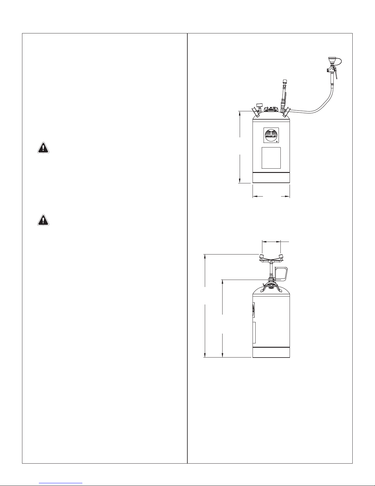
Installation S19-690
Step 1: Install eyewash and hose spray
1. Remove the plastic dust plug from the bottom
of the yoke assembly and discard. Attach the
eyewash yoke assembly to the tank. Max. torque
150 in-lbs.
2. Connect the hose spray to the hose with pipe
sealant. Do not attach the body wash sprayhead
(Item 9.3) at this time.
3. Remove the plug from the eyewash yoke base
and discard. Connect the hose with pipe sealant.
4. Attach the pressure gauge to the adapter on
the pressure side of the tank with pipe sealant
(supplied by installer) as shown on page 6.
IMPORTANT: When attaching the pressure
gauge and hose spray to the tank outlet,
hold the adapter (item 3) with a wrench
to prevent stripping. Failure to do so may
damage the seal and cause leakage. Max.
torque 150 in-lbs.
Step 2: Fill tank and pressurize
1. If the tank is pressurized, relieve tank pressure by
pulling up on relief tank tab in center of cover until
pressure gauge reads “0.”
3
⁄8"
24
(619mm)
12¼"
(311mm)
IMPORTANT: DO NOT open cover until
pressure gauge reads “0”!
2. Open the tank by pulling up on the wire handle
located on top of the Quicklock cover. Push down,
rotate and remove. Fill the container with 7½
gallons of potable water. Replace the cover.
3. After filling the tank with water and before
pressurizing the unit, cycle the valve from the
closed to open and back to closed. Pressurize the
tank to 90 psi by applying air pressure to the tank
valve located beneath the pressure gauge.
NOTE: Relief valve is designed to automatically vent at
100-130 psi to prevent the tank from overpressurizing.
Step 3: Flush tank
1. Discharge the water through the eyewash and
hose spray for at least five minutes to flush the
system.
2. Attach the body wash sprayhead.
3. Refill the tank and pressurize as explained in Step
2 outlined above.
NOTE: Let unit stand for one hour. If there is a
noticeable pressure drop, repressurize and let
stand for one hour. If problems persist, consult the
Troubleshooting guide found on page 5.
NOTE: This unit will provide 15 minutes of cleansing
action. Take the injured person immedi ately to a
normal emergency station for additional cleansing and
treatment.
6"
(152mm)
34"
(864mm)
26"
(660mm)
Bradley Corporation • 215-321C Rev. N; ECM 09-05-0003 4/14/09
3
S19-690, S19-690LHS Installation
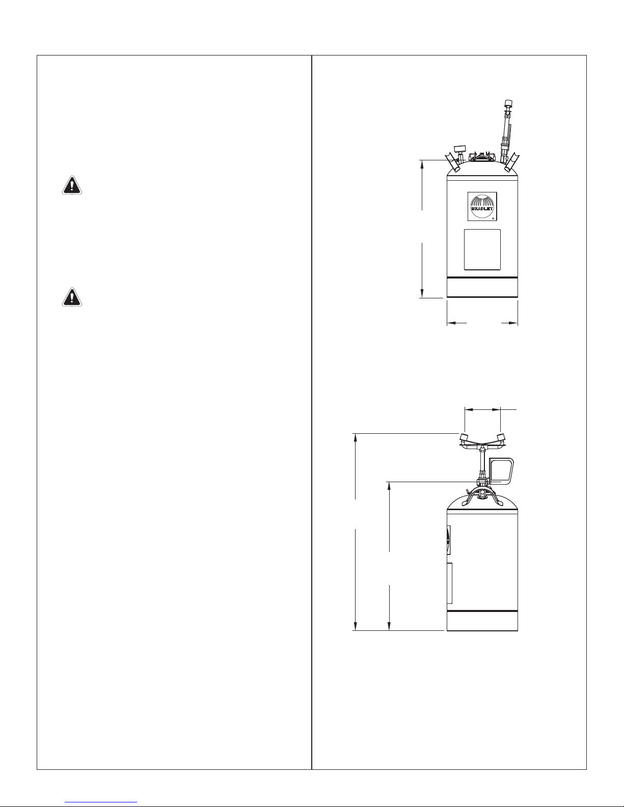
Installation S19-690LHS
Step 1: Install eyewash
1. Remove the plastic dust plug from the bottom
of the yoke assembly and discard. Attach the
eyewash yoke assembly to the tank. Max. torque
150 In-Lbs.
2. Attach the pressure gauge to the adapter on
the pressure side of the tank with pipe sealant
(supplied by installer) as shown, page 7.
IMPORTANT: When attaching the pressure
gauge to the tank outlet, hold the adapter
(item 3) with a wrench to prevent stripping.
Failure to do so may damage the seal and
cause leakage. Max. torque 150 in-lbs.
Step 2: Fill tank and pressurize
1. If the tank is pressurized, relieve tank pressure by
pulling up on relief tank tab in center of cover until
pressure gauge reads “0.”
IMPORTANT: DO NOT open cover until
pressure gauge reads “0”!
2. Open tank by pulling up on wire handle located on
top of the Quicklock cover. Push down, rotate and
remove. Fill container with 7½ gallons of potable
water. Replace cover.
3. After filling the tank with water and before
pressurizing the unit, cycle the valve from the
closed to open and back to closed. Pressurize
tank to 90 psi by applying air pressure to the tank
valve located beneath the pressure gauge.
NOTE: Relief valve is designed to automatically vent at
100-130 psi to prevent the tank from overpressurizing.
3
24
⁄8"
(619mm)
12¼"
(311mm)
6"
(152mm)
Step 3: Flush tank
1. Discharge the water through the eyewash for at
least five minutes to flush the system.
2. Refill the tank and pressurize as explained in Step
2 outlined above.
NOTE: Let unit stand for one hour. If there is a
noticeable pressure drop, repressurize and let
stand for one hour. If problems persist, consult the
Troubleshooting guide found on page 5.
NOTE: This unit will provide 15 minutes of cleansing
action. Take the injured person immedi ately to a
normal emergency station for additional cleansing and
treatment.
34"
(864mm)
26"
(660mm)
4
4/14/09 Bradley Corporation • 215-321C Rev. N; ECM 09-05-0003

Installation S19-690, S19-690LHS
Maintenance
WARNING: Water preservatives protect potable water from bacteria, fungi and algae growth for up to
four months. If a water preservative is not used with this eyewash, it is recommended that the tank
be cleaned weekly or as often as needed. Infection, loss of vision or other serious injury may result
from misuse of this eyewash. DO NOT use expired, cloudy, colored or contaminated solution. DO
NOT open preservative bottle if safety seal is broken. DO NOT save unused solution.
Step 1: Inspect eyewash unit
1. Visually inspect the pressure gauge weekly to ensure the unit is maintaining the proper pressure. If the unit is not
working properly, remove it from the hazard area immediately and refer to the troubleshooting instructions. For further
assistance, contact the Bradley Corporation.
Step 2: Clean eyewash unit
When using potable water only:
1. Empty the tank any time from once per week to once per month, depending on the quality of your water supply. The
manufacturer is not responsible for variations in the water supply.
2. Clean the inside of the tank using warm water and mild soap. Rinse the tank thoroughly with warm water.
3. Refill the eyewash tank following the procedure outlined in Step 2 found on page 3.
When using potable water and water preservative (recommended):
1. Empty the tank at least once every 120 days.
2. Clean the inside of the tank using warm water and mild soap. Rinse the tank thoroughly with warm water.
3. Refill the eyewash tank with potable water and the contents of an 8-ounce bottle of water preservative (refer to the
procedure outlined in Step 2 found on page 3).
• To order potable water preservative, contact your Bradley representative or local distributor and ask for part number
S19-865.
Troubleshooting
1. If pressure relief valve relieves prior to the required pressure, do the following (when in the unpressurized condition):
• Tighten the valve completely into the cap by turning the gray hex head portion of the pressure relief valve
clockwise. Do not use a wrench.
• Pull up on the relief valve ring and ensure that the ring is not preventing the valve from closing completely. Push on
the center pin of the relief valve to ensure that it is completely closed. Repressurize tank to required pressure. This
may have to be done several times to get the valve to seat completely.
2. If the pressurized tank loses pressure over time, check the connections with diluted liquid dish soap or children’s
bubbles to identify the leak location. Tighten the connection slightly and test again.
Bradley Corporation • 215-321C Rev. N; ECM 09-05-0003 4/14/09
5
S19-690, S19-690LHS Installation
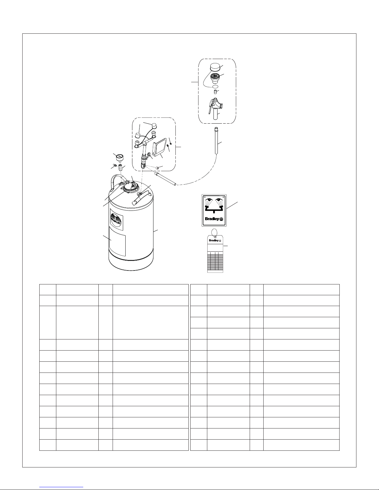
Assembly of Components and Parts List - S19-690
9.4
9.3
9
9.2
9.1
2.1
2.3
8
2
4
3
5
1.22
2.4
2.5
2.2
2.6
1.3, 1.4
1.3, 1.5
7
1.2, 1.21
P.O. BOX 309, MENOMONEE FALLS, WI 53052-0309 USA
TEL: 1-800-BRADLEY FAX: (262-251-5817)
http://www.bradleycorp.com
114-051
1
1.1
R
P.O. Box 309, Menomonee Falls, WI 53051
TEST THIS UNIT EACH WEEK
DIESES GERÄT 1ST WÖCHENTLICH ZU PRÜFEN.
ESSAI HEBDOMADAIRE
Test-operate valve(s) each week and sign below.
Report any malfunctions immediately.
Ventil(e) wöchentlich im Testbetrieb prüfen, bestätigt
durch Unterschrift. Jegliche Störung sofort melden.
Test le fonctionnement des valves chaque semaine et
signe en bas. S'il y à quelque chose qui ne va pas fait
un rapport immédiatement.
Date
Datum
Date
6
Signed
Date Signed
Unterschrift
Date
Signed
Signe
Date
Signed
Item Part No. Qty. Description Item Part No. Qty. Description
1 S39-785 1 Tank, 10-Gallon
1.1 204-641 1 Operating Instr. Label, English
2.4 153-372R 1 Adapter
2.5 142-002DA 1 Lockwasher
204-641FC 1 Operating Instr. Label, French
204-641M 1 Operating Instr. Label, Spanish
1.2 S44-024 1 Lid Assembly
1.21 269-1410 1 Gasket
1.22 269-1642 1 Relief Valve
1.3 269-1411 2 O-Ring
1.4 269-1516 1 Draw Tube
1.5 269-1515 1 Level Indicator Tube
2 S05-182 1 Eyewash Valve Assembly
2.1 107-371 2 Tethered Dust Cover
2.2 S08-336 1 Handle/Label Assembly
2.3 110-215 1 Nut
S45-2410 includes Items 1.21, 1.3
6
4/14/09 Bradley Corporation • 215-321C Rev. N; ECM 09-05-0003
2.6 169-043 1 Plug (do not save)
3 153-451 1 Adapter
4 169-786 1 Pressure Gauge
5 S27-320 1 Tank Valve Assembly
6 204-421 1 Emergency Inspection Tag
7 114-051 1 Safety Sign
8 S89-002 1 3/8" Yellow Tube
9 S19-787 1 Hose Spray
9.1 S27-265 1 Valve, Hose Spray
9.2 113-544A 1 Close Nipple, Plated
9.3 S05-158 1 Body Wash Sprayhead
9.4 S53-063 1 Tethered Dust Cover
 Loading...