

Bradley S19-671, S19-672 Installation Manual
P.O. BOX 309
MENOMONEE FALLS, WI 53052-0309 USA
TEL: 1-800-BRADLEY FAX: (262-251-5817)
http://www.bradleycorp.com
Installation
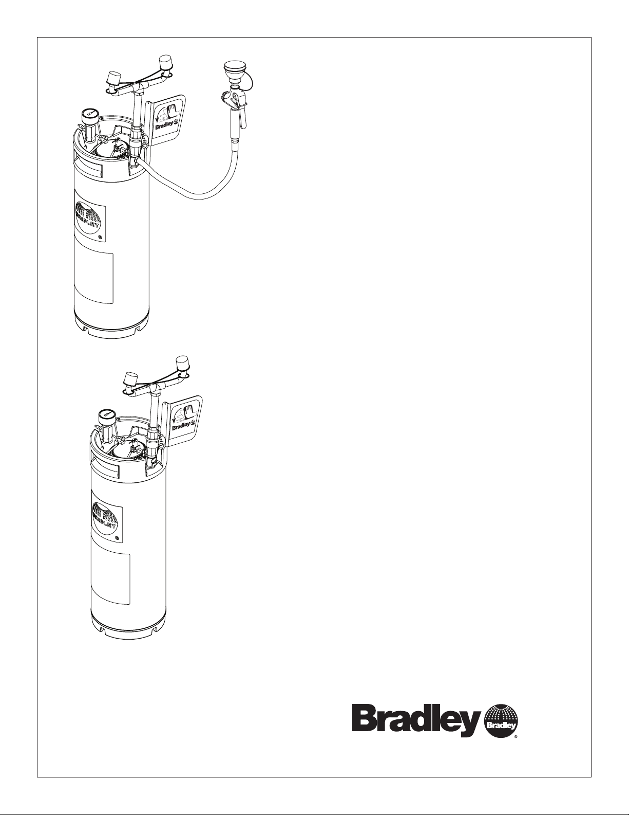
S19-672
5-Gallon Tank with Eyewash and
Hose Spray
Réservoir de 5 gallons avec douche
oculaire et douchette
P.O. BOX 309
MENOMONEE FALLS, WI 53052-0309 USA
TEL: 1-800-BRADLEY FAX: (262-251-5817)
http://www.bradleycorp.com
S19-672
S19-671
Depósito de 5 galones con lavaojos
y manguera de aspersión
S19-671
5-Gallon Tank with Eyewash
Réservoir de 5 gallons avec
douche oculaire
Depósito de 5 galones con lavaojos
Table of Contents
Pre-Installation Information ........................... 2
Dimensions ........................................3
Eyewash Installation ................................ 3
Filling the Tank......................................4
Maintenance & Troubleshooting ....................... 5
S19-672 Components & Parts List ..................... 6
S19-671 Components & Parts List ..................... 7
Table des matières
Avant l’installation .................................. 8
Dimensions ........................................9
Installation de la douche oculaire ...................... 9
Remplissage du réservoir ............................10
Entretien et dépannage ............................. 11
S19-672 Composantes et liste des pièces .............. 12
S19-671 Composantes et liste des pièces .............. 13
215-321B Rev. V; ECN 12-05-003C
© 2012 Bradley
Page 1 of 19 10/19/2012
Contenido
Información previa a la instalación .................... 14
Dimensiones ......................................15
Instalación del lavaojos ............................. 15
Llenar el tanque....................................16
Mantenimiento y resolución de problemas .............. 17
S19-672 Componentes y lista de piezas................ 18
S19-671 Componentes y lista de piezas................ 19
P.O. Box 309, Menomonee Falls, WI USA 53052-0309
PHONE 800.BRADLEY (800.272.3539) FAX 262.251.5817
bradleycorp.com
S19-672, S19-671 Installation
IMPORTANT
Installation
P.O. Box 309, Menomonee F
UNIT EACH
TEST THIS
DIESES GERÄT 1ST
ESSAI HEBDOMA
Test-operate valv
Report any malfunctions immediatel
Ventil(e) wöc
durch Unterschrift. Jegliche Störung sofor
60˚ F
R
WI 53051
alls,
WEEK
WÖCHENTLICH ZU
DAIRE
e(s) each week and sign
hentlich im
Test le fonctionnement des v
signe en bas. S'il y à quelqu
un rappor
Date
below.
PRÜFEN.
y.
Testbetrieb prüfen, bestätigt
alves chaque semaine et
e chose qui ne v
t immédiatement.
Signed
Unterschrift
Signe
Datum
Date
THIS
SIDE
UP
t melden.
a pas fait
Signed
Signed
Date Signed
Date
Date
Fisher Safety
A Fisher Scientific Company
1-800-772-6733
Packing List
100˚ F
Read this installation manual completely to ensure proper installation, then file it with the
owner or maintenance department. Compliance and conformity to drain requirements and
other local codes and ordinances is the responsibility of the installer.
Separate parts from packaging and make sure all parts are accounted for before discarding
any packaging material. If any parts are missing, do not begin installation until you obtain
the missing parts.
The inspection and testing results of this equipment should be recorded weekly to verify
proper operation. This equipment should be inspected annually to ensure compliance with
ANSI Z358.1.
Workers who may come in contact with potentially hazardous materials should be trained
regarding the placement and proper operation of emergency equipment per ANSI Z358.1.
For questions regarding the operation or installation of this product, visit www.bradleycorp.
com or call 800.BRADLEY (800.272.3539).
Product warranties and service parts information may also be found under ”Products” on our
web site at www.bradleycorp.com.
This unit is to be used with tepid, potable water as defined by ANSI Z358.1. (Note: avoid
prolonged exposure to ambient heat sources above 100° F, or below 60° F).
NOTICE! Avoid cleaners containing organic solvents, alcohols, and hydrocarbons.
Rinse with water after cleaning.
Supplies and Tools Required:
Pipe sealant
Air pressure equipment or supply (clean and free of oil and contaminants) capable of up to 100 psi.
Sign-mounting hardware
Adjustable wrench
2
10/19/2012 Bradley•215-321B Rev. V; ECN 12-05-003C
Installation S19-672, S19-671
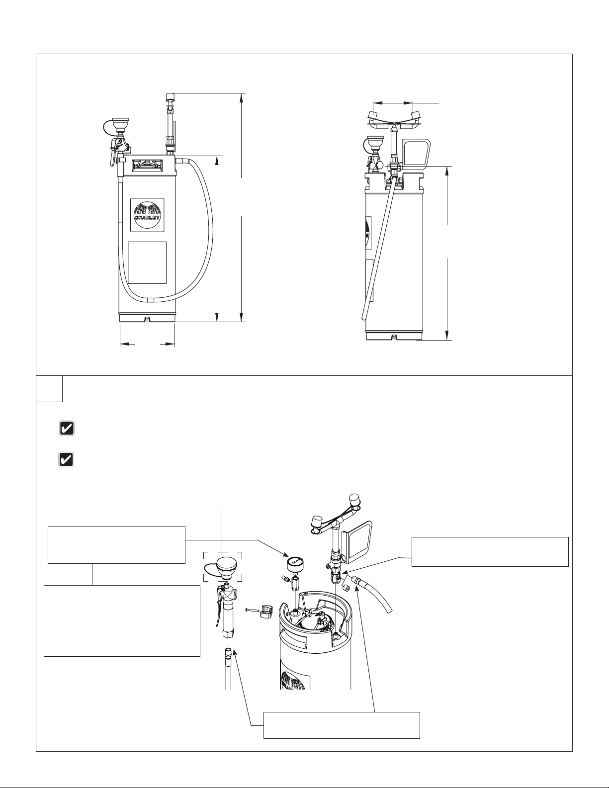
Dimensions
6"
(152mm)
35⁵⁄₈"
(905mm)
27½"
(699mm)
25"
(635mm)
8½"
(216mm)
1
Eyewash installation
Remove the plastic dust plug from the bottom of
the yoke assembly and discard.
Hose spray for S19-672 model only. Do not attach
body wash spray head at this time.
Body Wash Spray Head
Attach the pressure gauge to
the adapter on the pressure
side of the tank with pipe
C
sealant (by installer).
NOTICE: When attaching the pressure
gauge and hose spray to the tank
outlet, hold the adapter (item 3) with a
wrench to prevent stripping. Failure to
do so may damage the seal and cause
leakage. Max. torque 150 in-lbs.
Attach the eyewash yoke assembly
A
to the tank. Max. torque 150 In-Lbs.
Connect the hose with pipe sealant.
(by installer)
B
Bradley•215-321B Rev. V; ECN 12-05-003C 10/19/2012
3

S19-672, S19-671 Installation
2
Filling the Tank
Fill tank and pressurize
CAUTION! DO NOT open the cover until the pressure gauge reads “0.”
1. Open the tank by pulling up on the wire handle located on top of the Quick-lock cover. Push down, rotate and remove. Make
sure that the interior of the container is clean. Fill the container with 4 gallons of tepid potable water.
2. Replace the cover and secure by pulling up on the cover and down on the wire handle.
3. After filling the tank with tepid water and before pressurizing the unit, open the activation valve to the full open position and
remove the dust covers from the eyewash heads.
4. Located beneath the pressure gauge is an air valve. Remove protective cover and begin to pressurize the unit by applying
pressured air through the valve. As soon as water begins discharging from the eyewash heads, close the activation lever
completely. Finish pressurizing the tank to 90 psi and replace the air valves protective cover.
If this is the initial startup of this unit or if the unit has been unfilled and/or un-pressurized for a prolonged period of time the
unit should be flushed out per the procedure below.
Prior to placing unit in service let unit stand for one hour. If there is a noticeable pressure drop, re-pressurize and let
stand for an additional hour. If unit continues to exhibit pressure loss DO NOT place unit in service and consult the
Troubleshooting guide found on page 6 of this manual.
CAUTION! Relief valve is designed to vent automatically at 100-130 psi to prevent the tank from over pressurizing.
If the gauge ever reads more then 130 psi immediately open the pressure relief valve manually by pulling
up on the relief valve tab until the pressure reads zero. Remove the unit from service and consult the
troubleshooting guide found on page 6 in this manual for steps to correct the problem. Return the unit to
service only when over-pressurization issue is corrected.
Flush tank
1. Be sure the unit is assembled, filled and pressurized according to Steps 1 & 2 above, (If this is the initial start up of the unit
the body wash spray head will not be attached to the drench hose activation valve at this time.)
2. Discharge the water through the eyewash and hose spray (if provided with unit) for at least five minutes to flush the system.
3. Flush all remaining fluid in the tank.
4. Attach the body wash sprayhead (S19-672).
5. Refill the tank and pressurize as described in Step 2 above.
4
10/19/2012 Bradley•215-321B Rev. V; ECN 12-05-003C
 Loading...