

Page 1
Installation
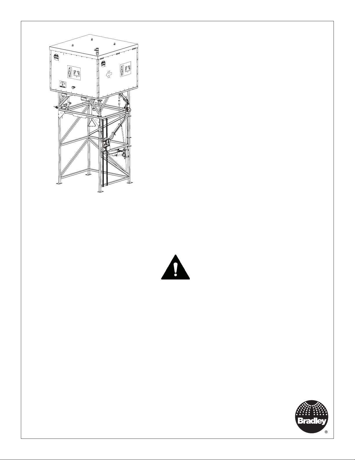
S19390 Series
Gravity Fed Safety Shower
General Area
Table of Contents
Safety Information ...............................2
Dimensions .................................. 3-4
Shipping and Handling Instructions..................5
Gravity Fed Safety Shower Preconstruction Guide ......6
Storage and Preservation Guide ....................7
Secure Frame to Concrete Pad .....................7
Prepare Enclosure...............................8
Electrical Connections ............................9
Filling Water Tank ..............................10
Signaling System Maintenance ....................11
Energizing the Unit .............................11
Test the Signaling System ........................11
Start-Up Check List .............................12
Weekly Inspection Checklist ......................13
Troubleshooting ................................14
Read the instructions in this manual before
beginning installation. Save these instructions
and refer to them for inspection, maintenance
and troubleshooting information.
For questions regarding the operation, installation or maintenance of this product, visit bradleycorp.com
or call 800.BRADLEY (800.272.3539).
Product warranties and parts information may also be found under ”Products” on our web site at bradleycorp.com.
P.O. Box 309
+1 262 251 6000
bradleycorp.com
215-1871 Rev. A; ECN 17-05-055
© 2018 Bradley
Page 1 of 14 2/13/2018
Menomonee Falls, WI 53052 USA
800 BRADLEY (800 272 3539)
Page 2

S19390 Series Installation
Safety Information
To reduce the risk of serious injury or death:
Installation
The installation and location of all safety drench showers, eye and eye/face washes must comply with the
requirements of ANSI/ISEA Z358.1.
Before installation make sure that this equipment will meet the requirements of potential hazardous contaminants in
your location.
Workers who may come in contact with potentially hazardous materials should be trained regarding the placement
and proper operation of emergency equipment per ANSI/ISEA Z358.1.
Installation of this system must be completed by a qualified plumber and electrician in compliance with all national
and local codes. Compliance and conformity to drain requirements and other local codes and ordinances is the
responsibility of the installer.
This unit is to be used with clean, potable water as defined by ANSI/ISEA Z358.1. Bradley recommends the use of
water preservative with this unit. Water preservative may be purchased from various distributors; please contact your
local distributor. If algae or other containments are allowed into the tank or develop in the tank the shower may not
function properly.
Weekly Inspections
Make sure the shower and face wash fixtures are ready to be used when needed by performing regular checks
and maintenance. Weekly inspections must be conducted on all self-contained safety equipment to make sure a
suitable flushing fluid supply is present, check if fluid needs to be changed or supplemented, and to make sure the
equipment is in good operating condition. See page 13 for additional information.
Water Temperature
ANSI/ISEA Z358.1 requires tepid water. Suitable range is 60°F to 100°F (16°C to 38°C). Personal injury is possible
outside this temperature range. If ambient temperature may drop below 60°F (16°C), install a heater with a
continuous power supply. If model selected does not include tank water heater, the ambient temperature will affect
the tank temperature and must be placed in an appropriate location.
Moving the Tank
Drain the tank completely before moving. Lifting or moving a tank with water may cause damage to the unit or a loss
of stability when in motion.
To avoid product or property damage:
• Unit is designed to be installed indoors or in locations above freezing (32°F (0°C)).
• Make all water and electrical connections at temperatures above freezing (32°F (0°C)).
2
2/13/2018 Bradley • 215-1871 Rev. A; ECN 17-05-055
Page 3
Installation S19390 Series
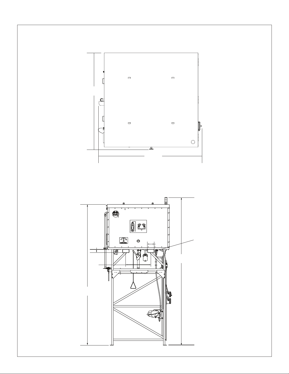
Dimensions
Top View
(mm)
77"
(1956)
82"
(2083)
Front View
3-1/2"
(762)
168-7/8"
(4290)
(89)
30"
7-1/2"
(191)
Fork Truck
Slots
177-3/8"
(4506)
Bradley • 215-1871 Rev. A; ECN 17-05-055 2/13/2018
3
Page 4
S19390 Series Installation
Dimensions
Left Side View Right Side View
Warning
Light
Beacon
Light
Optional
Tank Water
Heater (Inside
Enclosure)
Water Inlet
(mm)
92-3/8"
(2346)
Area Light
with Motion
Sensor Option
See water heater manual
to adjust temperature.
4
2/13/2018 Bradley • 215-1871 Rev. A; ECN 17-05-055
Page 5
Installation S19390 Series
Shipping and Handling Instructions
Approximate Total Weight
Base Model No. Description
S19390 Gravity Fed Safety Shower 2200 lbs.*
*Weight will vary depending on options selected.
Transporting the Gravity Fed Safety Shower
Bradley Safety Showers are transported within the continental United States and Canada via commercial truck. Unit
ships in two pieces (steel frame and enclosed water tank). See page 8.
WARNING Always use proper lifting techniques when moving the safety shower. Weight distribution is
unbalanced, and the product may tip over if lifted improperly. Make sure lifting equipment is
properly rated for this load. Overloading could cause serious injury or death from tip over.
Bottom Lift: Locate lifting points at base of tank enclosure or shipping pallet. Notice: Lifting eyelets on top of tank
enclosure are only for lifting the cover. Do not use to lift the entire tank enclosure.
If immediate destination of the unit is storage, refer to the Storage and Preservation Guide.
Each shower will be accompanied by document packaging that includes the installation instructions and electrical
schematics, if applicable. Store safety enclosure documents for reference.
If equipment is relocated, always perform a functional test before returning to service.
(less shipping skids)
WARNING Drain the tank completely before moving. Lifting or moving a tank with water may cause a loss
of stability and tipover.
Storage and Preservation Guide
Keep Bradley Gravity Fed Safety Shower stored in original packaging until installation.
• Store Bradley Safety Shower where temperatures are above 35°F (5°C) at all times.
• Indoor storage is recommended.
• Minimize excessive transportation around a job site to reduce risk of damage.
If the Bradley Safety Shower is stored in an outdoor environment, care should be taken to protect the Safety Shower
from rain or other falling precipitation via tarp or other waterproof material and from runoff and accumulation of
ground water from any source that may exceed 3” depth.
Bradley • 215-1871 Rev. A; ECN 17-05-055 2/13/2018
5
Page 6

S19390 Series Installation
Gravity Fed Safety Shower Preconstruction Guide
Thank you for your business. The purpose of Bradley’s Gravity Fed Safety Shower preconstruction guide is to provide
important pre-installation information to the customer that has determined their product specification needs are met
by a Gravity Fed Safety Shower configuration. For system details refer to Bradley’s Product Technical Data sheets. If
additional information is still required contact the Bradley Corporation Technical Service Department.
Technical Documents Available
• Product Technical Data Sheets
• Storage and Preservation Guide
• Installation Instructions
Recommended Equipment, Materials and Supplies to be provided by Installer
• Concrete slab rated to support a minimum 6000 psi vertical static load. The slab should be sufficiently
anchored to resist upheaval or movement due to environmental causes such as wind loads on the
shower.
• Drain able to accommodate 30 gpm discharge for shower and eye/face wash.
• (8) 1/2” diameter Anti-Corrosion Expansion Anchors (2 per mounting plate)
• Properly rated lifting equipment which exceeds the total weight of the shower unit
• Electrical supply materials (if applicable)
• Plumbing supply materials (if applicable)
Pre-installation Instructions
IMPORTANT: Separate parts from packaging and make sure all parts are accounted for before discarding
any packaging material. If any parts are missing, do not begin installation until you obtain the
missing parts.
• Survey the facility to ensure that the appropriate flushing system is installed per the ANSI/ISEA Z358.1
requirements. Identify a location that is capable of delivering a supply of power which will meet system
electrical requirements (if applicable).
• Review minimum electrical requirements based on the unit and options selected. Refer to wiring
schematic or system rating labels provided with unit.
• Confirm that the installation area is level.
• If concrete is not already present, pour a 6000 psi-rated concrete pad 80” x 72” minimum. The thickness
and foundation for this pad should be designed and constructed to meet the requirements of each site.
• Make allowances to ensure the electrical system is grounded prior to connecting power.
6
2/13/2018 Bradley • 215-1871 Rev. A; ECN 17-05-055
Page 7

Installation S19390 Series
Secure Frame to Concrete Pad
1. Place the frame in position, centering the unit on the concrete pad.
65-1/2"
(1664)
59"
(1499)
50"
(1270)
2. Secure the frame to the concrete using suitable concrete anchoring devices supplied by the installer.
Anchoring devices must be a minimum 6” long and 1/2” diameter, with 2 per corner of the frame.
WARNING Follow anchor manufacturer’s instructions and local requirements to make sure frame is
securely connected to the concrete pad.
Bradley • 215-1871 Rev. A; ECN 17-05-055 2/13/2018
7
Page 8

S19390 Series Installation
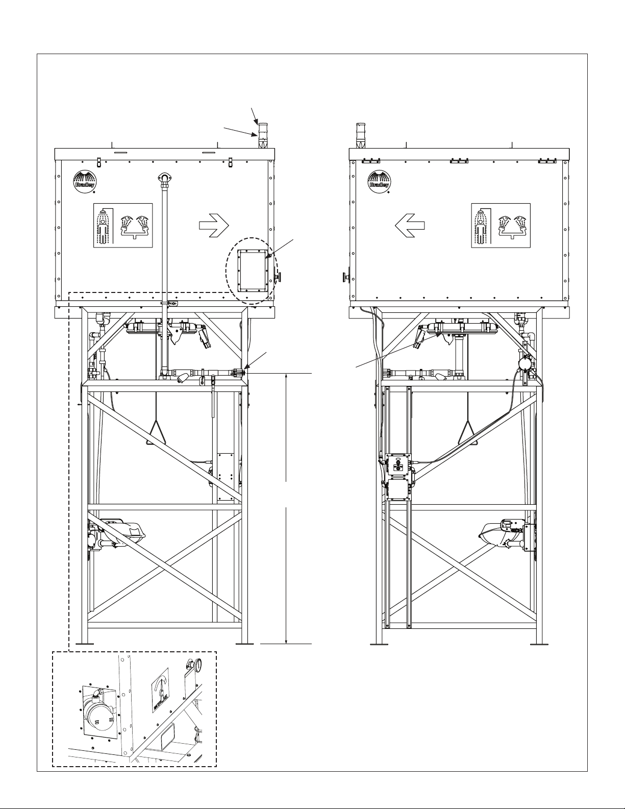
Prepare Enclosure
3. Use a properly sized fork truck to place the empty tank enclosure onto the frame (secured to the concrete pad in
Secure Frame to Concrete Pad, pg. 7). Locate the tank enclosure on the frame, aligning the two guide pins on
the top of the frame with the corresponding holes in the bottom of the tank enclosure. Notice: The 4 eyelets are
only for lifting off the cover to maintain or repair the water tank or other components in the enclosure.
4. Fasten the two components together with the supplied fasteners(8 sets of 3/8" fasteners). Tighten nut securely.
5. Attach the pipe unions that connect the optional eye/face wash and the tank drain to the corresponding pipe
fittings below the tank.
6. Attach the shower’s pull rod to the lever on the ball valve.
3
4
2
3
6
2
4
5
4
3
8
2/13/2018 Bradley • 215-1871 Rev. A; ECN 17-05-055
Page 9

Installation S19390 Series
Electrical Connections
Some steps apply to optional components. Review and follow if applicable.
WARNING To prevent personal injury or damage to the electrical components, electrical connections
should be made be a qualified electrician. Make sure electrical supply is disconnected
(circuit protection to be provided by installer) and follow all lockout/tagout procedures when
performing any electrical maintenance or installation/connection to the system.
NOTICE:
• It is recommended that installation be completed when ambient temperature is above freezing.
• To avoid damage to the water heater, do not power the water heater unless the tank is filled with water.
1. Verify that the electrical supply is
disconnected.
2. Connect the optional signal system light
4-pin cable to the signal system box.
3. Connect the optional signal system
sensor 3-pin cable to the signal system
box. Connect the 3-pin cable from the face
wash sensor to the junction box.
4. Connect the optional water heater/light
conduit cable to the fuse box.
5. Install incoming power conduit to the
electrical box (installer must provide
suitable disconnect and circuit protection
devices).
6. Refer to the system’s electrical wiring
drawings for proper connections.
Optional Signal
System Light
(4-Pin Cable)
Optional Water
Heater Conduit
Cable
Fuse Box for
Water Heater
and/or Area
Light Options
Optional
Signaling
System
Power Inlet Port,
Optional Signal
System Sensor
(3-Pin Cable)
3/4"
Bradley • 215-1871 Rev. A; ECN 17-05-055 2/13/2018
9
Page 10

S19390 Series Installation
Filling Water Tank
1. Ensure the shower, eye/face wash and drain
valves are in the closed position.
2. At the side of the tank where the water inlet
plumbing is located, verify that the water inlet
drain valve is closed. Remove the 1-1/2” cam
lock plug from the fitting and connect a potable
water source, then fill the tank with water. A
float valve should limit the water allowed into a
full tank, but care should be taken to not overfill
the tank. The water level indicator on the front of
the tank will show the water level.
3. When the tank has been at least partially
filled (approximately 100 gallons or 350 liters
minimum), or when the tank is full, the shower
and eye/face wash should be activated briefly
(10-20 seconds) to flush water through the
fixtures and remove trapped air.
If the water flow pattern from the showerhead or
eye/face wash is not stable or fully shaped, verify
that there are no obstructions. The showerhead
and the eye/face wash head can be removed for
inspection and cleaning.
Water Inlet
Water Inlet
Drain Valve
4. Add water preservative (not included) to the
water tank by opening the tank enclosure cover
and the inner tank lid. Follow the preservative
manufacturer’s instructions for proper use of
their product.
Some water may need to be added to the tank to
achieve full capacity after testing the fixtures.
5. Check for leaks at all connections throughout
the system.
6. With the water supply turned off, open the water
inlet drain valve to empty the water inlet piping,
then disconnect the water supply. Replace the
cam lock plug in the water inlet fitting and lock
the cam levers in the closed position.
10
2/13/2018 Bradley • 215-1871 Rev. A; ECN 17-05-055
Page 11

Installation S19390 Series
Energizing the Unit
1. Verify that all water and electrical connections have been properly made.
WARNING To reduce the risk of electrical shock close all electrical boxes before energizing the unit.
2. Turn on the power at the electrical disconnect switch (supplied by installer).
3. Complete Startup Checklist and the Weekly Visual Inspection Checklist (included in this manual) at this time.
Test the Signaling System
1. Apply power to the alarm branch circuit. The alarm
should remain in the OFF position and the beacon and
area light illuminate (if applicable). The signal light will
not illuminate.
2. Open the eye/face wash valve. The horn should sound
and the signal light flash shortly after water flows from
the system. If there is the optional beacon light, this
beacon light will turn off once the fixture is activated
(the signal light will stay on, flashing). The area light will
always stay on.
Horn
3. If present, use the auto reset on/ off switch to silence
the horn during a water-flow event. Toggling the switch
to silence mode will shut off the horn but allow the
signal light to keep flashing. All units can be silenced by
deactivating the flow.
4. Shut off the eye/face wash flow valve. If applicable, the
signal light should stop flashing and the beacon light
will turn back on.
Discontinuing the flow will automatically reset the silence feature.
5. Repeat steps 1 through 4, this time using the drench shower only.
The alarm signaling system is designed to work properly even if both the eye/face wash and drench shower are used
simultaneously. The alarm will continue to operate so long as either the eye/face wash or drench shower is still in use.
Auto Reset On/Off Switch
Bradley • 215-1871 Rev. A; ECN 17-05-055 2/13/2018
11
Page 12

S19390 Series Installation
S19390 Gravity Fed Safety Shower Start-up Checklist
(some items refer to optional components)
System Flush (All Electrical Power off for System Flush)
• System has been flushed using the emergency fixture.
• Water is clear and free of any contamination, particles or discoloration.
• Check all system fittings for water leaks.
Bradley drench shower and eye/face wash activation checklist
• The horn and warning lights have been activated when the shower and/or eye/face wash are running.
• The alarm silences and the warning light continues to flash when the horn silence button is depressed.
• All system fittings have been checked for water leaks.
• The water temperature at the drench shower and eye/face wash is tepid (per ANSI/ISEA Z358.1). If cold water is initially added to the tank, allow up to 20 hours
for the water heater to warm the water.
• The proper spray pattern is maintained for the drench shower and eye/face wash for the duration of the test.
Bradley drench shower and eye/face wash deactivation checklist
• After the shower and eye/face wash are all turned off, the warning light is turned off and the system is reset when the horn silence button is depressed for the
second time.
Verify other enclosure system checks
•
The interior light is always on, if present, or turns on with motion, if motion sensor is present. (See motion sensor manual for adjustment to motion sensor timer).
• The control panel is not damaged (no cracks, voids, holes or other functional or structural issues).
Complete OKInspector
Initials
• The certification and serial number labels are present.
System Start-up and Test Checklist Completion & Approval
System Serial Number:
Inspection Date:
Inspector Signature:
S19390 Gravity Fed Safety Shower
12
2/13/2018 Bradley • 215-1871 Rev. A; ECN 17-05-055
Page 13

Installation S19390 Series
Weekly Inspection Checklist
Survey the facility to ensure that the appropriate flushing system is installed per the ANSI/ISEA Z358.1 requirement.
Safety Data sheets can help determine what flushing system is appropriate for your hazards.
S19390 Gravity Fed Safety Shower
Weekly Inspection Checklist
Inspect water tank.
• Verify tank is full.
• Tank water should be changed per preservative manufacturer's instructions.
Visually inspect lights.
• Power disconnect switch is in the "ON" position (if applicable).
• Beacon light is "steady on." If this light is blinking, troubleshooting may be needed to determine what is out of normal limits (if applicable).
Inspect all eye/face wash and drench shower systems to ensure they are compliant and operational in case of an emergency.
• Replace any broken or missing parts immediately.
• Remove any obstructions or trip hazards
• Ensure the system is on the same plane as the hazard and within the minimum distance to the hazard.
• Evaluate if the equipment needs to be protected against freezing.
• Inspect the tank's water temperature to ensure it is tepid per ANSI/ISEA Z358.1.
Document inspection on the unit's inspection tag and in any centrally-controlled documentation log.
Complete OKInspector
Initials
S19390 Gravity Fed Safety Shower
Monthly Inspection Checklist
Activate all eye/face wash and drench shower systems to ensure they are compliant and operational in case of an emergency.
• Use a Bradley drench shower tester with a bucket to contain the water released from the drench shower. Measure the water released from the shower to ensure it
complies with the 20 gpm ANSI minimum flow requirements.
• Activate the shower and eye/face wash (if present) whenever the water tank is filled, or monthly, to verify normal water flow and spray pattern.
• Turn OFF all water fixtures (shower and eye/face wash). Press the silence button to reset the system.
Complete OKInspector
Initials
Signaling System Maintenance
The Bradley Emergency Signaling System is designed to be virtually maintenance free. An occasional damp cloth wiping
of the clear dust cover is all that is needed to ensure maximum visual attention-getting ability.
Bradley • 215-1871 Rev. A; ECN 17-05-055 2/13/2018
13
Page 14

S19390 Series Installation
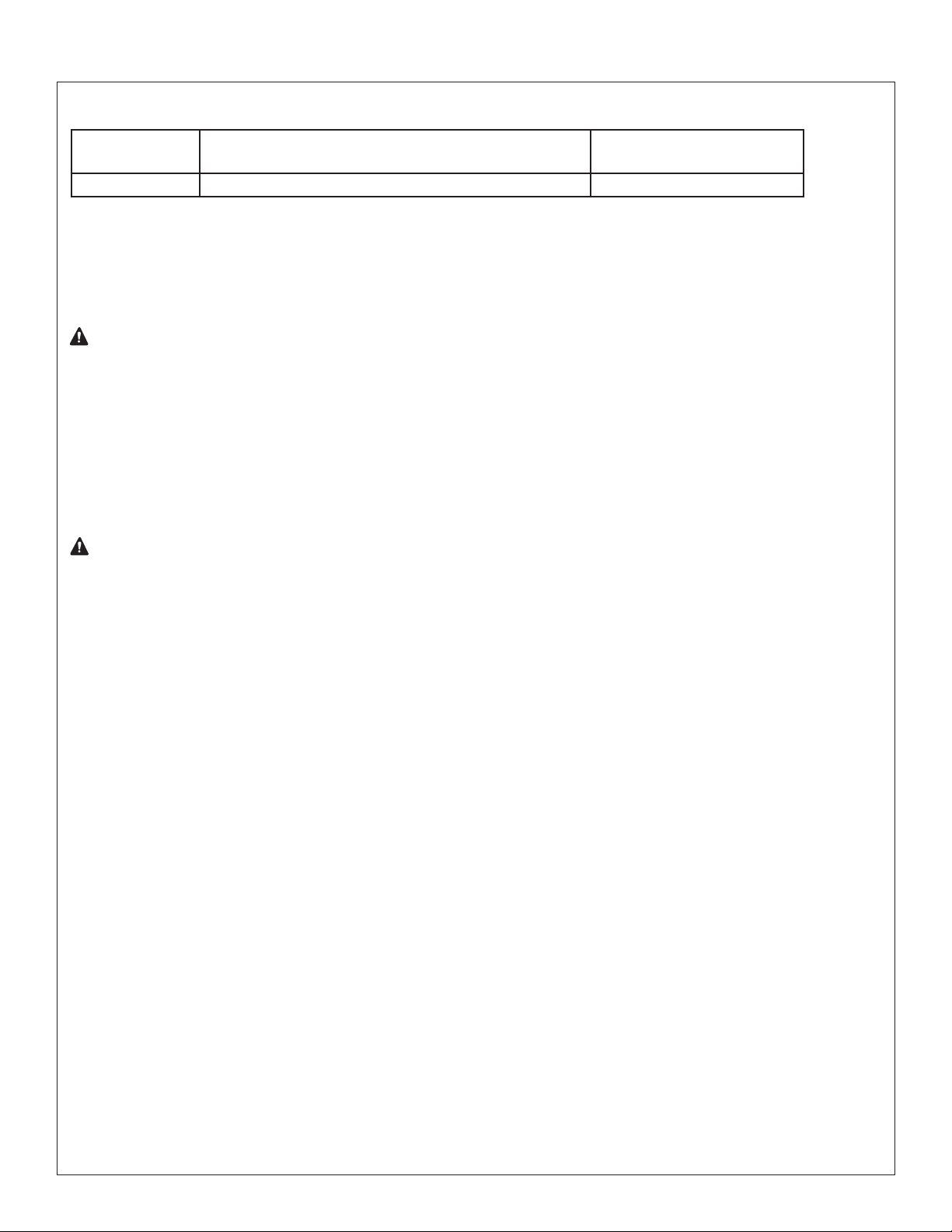
Troubleshooting
Should damage occur to the unit, it is recommended to contact the factory for repair instructions. Cleaning should be
conducted using rinse down water, DO NOT USE STEAM TO CLEAN.
Problem Cause Solution
Low water flow at drench
shower and/or eye/face wash
Difficulty filling the water tank. Wye strainer is plugged with
Water thermometer is not
reading true temperature.
Water level gage is not
reading the true water level.
Water tank interior is dirty. Cover of tank enclosure is not
Cover of tank enclosure is
very heavy to open.
The signal light and horn (if
applicable) does not operate
when water flows.
Debris in system. Disassemble the showerhead, clean and reassemble. Unscrew the
Empty water tank. Fill the tank with clean, potable water.
sediment or algae.
Component failure. Drain the tank of water and replace the thermometer.
Exterior arrow is loose on
shaft.
Interior cable mechanism is
loose, broken or jammed.
Water float inside the water
tank contains water and does
not float.
latched securely.
One or both gas springs has
failed. (Storage temperature
inside the tank enclosure
must be above -13°F.)
No power to the signal station. Check that the circuit breaker or fuse is supplying power to the
Component function. Check the two 3 Amp 24VDC fuses on the printed circuit board in
eye/face wash heads from the yoke, clean and reassemble. If still
clogged, replace the heads.
Remove the strainer screen, clean and replace.
Verify tank is full of water and fasten the arrow to the shaft so that it
points to the "full" mark.
Inspect and adjust the cable mechanism by opening the cover of the
tank enclosure or by opening the water heater access panel on the
side of the tank enclosure.
Replace the water float.
Inspect the two cover latches for proper movement and that the
hook is adjusted and tightened to make the latch toggle closed while
holding the cover snugly.
Open the cover so that there is no weight on the gas springs and
prop open the cover with a suitably strong and secure object.
Replace the gas spring(s). Carefully apply the cover weight and
verify that it is properly balanced by the gas springs.
signal station
the signal system enclosure.
Check the limit switches on the shower and the eye/face wash.
No input power. Check that there is 24VDC being supplied from the power supply
mounted on the printed circuit board in the signal system enclosure.
Installation error Check all electrical connections, including power supply at the quick-
connect cable, from the signal system to the switch.
Horn sounds and signal light
does not light.
Beacon light does not operate.
(This light should turn off
when the signal light turns on
and back on when the signal
light turns off.)
Area light does not operate. No power to the fuse panel. Check the incoming power.
14
Component function. Check light connections and filament in the light.
Fixture in use. Make sure that the switch contacts are open (horn and/or signal light
are not ON).
Power disconnected in error. Check that the circuit breaker or fuse is supplying power to the
signal station.
Component function. Check the 3 Amp 24VDC fuses on the print circuit board in the
signal station enclosure.
No input power. Check that there is 24VDC being supplied from the power supply
mounted on the print circuit board in the signal station enclosure.
Component failure. Check light connections and LED module in the light.
Component failure. Check the 1/2 amp fuses in the fuse panel. If one or more fuses are
blown, open and carefully check the circuit for shorts or electrical
faults.
Component failure. Check the LED for functionality and replace if necessary.
2/13/2018 Bradley • 215-1871 Rev. A; ECN 17-05-055
 Loading...