

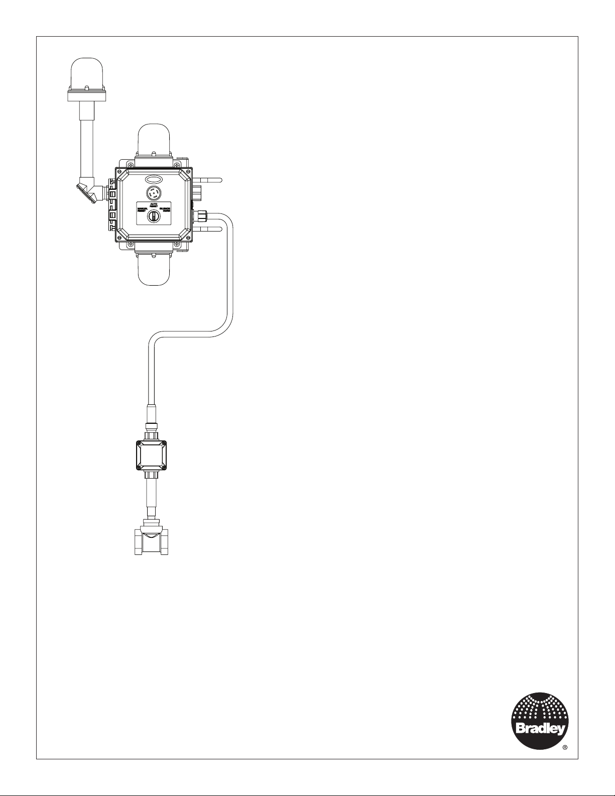
Bradley S19-323, S19-324DGW, S19-324 Wiring Diagram
Installation
S19-323
NEMA 3R
S19-324
NEMA 4X
Emergency Signaling System
Table of Contents
Pre-Installation Information ..........................2-3
Components......................................4-5
Install Flow Switch and Mount Assembly ................ 6
Connect Signaling Assembly to Flow Switch.............. 7
Complete Electrical Supply Connections................. 7
Test the Signaling System ............................ 8
Maintenance ...................................... 8
Remote Sensing Option.............................. 8
Servicing of Lights .................................. 9
Troubleshooting ................................... 10
Service Parts ...................................11-12
Wiring Diagram ................................... 13
Schematic ....................................... 14
S19-324DGW shown
215-1846 Rev. C; ECN 17-05-068
© 2017 Bradley
Page 1 of 14 11/21/2017
Menomonee Falls, WI 53052 USA
P.O. Box 309
800 BRADLEY (800 272 3539)
+1 262 251 6000
bradleycorp.com

S19-323, S19-324 Installation
WARNING
Power supplied to the unit should be between 90-264VAC, 50-60 Hz, 15 amp branch circuit with a
dedicated circuit breaker or fuse and should not supply power to any other device. Compliance
and conformity to local codes and ordinances is the responsibility of the installer.
Do not use this safety equipment in a location that does not match its hazardous location rating.
Verify the appropriate ratings prior to installation.
When making electrical connections be sure to follow all lockout–tagout safety procedures.
Flush the water supply lines before beginning installation and after installation is complete. Test
the unit for leaks and adequate water flow. Main water supply should be “ON” at all times unless
system is being serviced. Provisions shall be made to prevent unauthorized shutoff.
CAUTION
Supply the unit with clean, potable water.
NOTICE
Before installing this product, ensure that there are adequate clearances around the product and
activation of the product does not interfere with other products or obstructions.
It is recommended that all water supply and electrical connections be made at temperatures above
freezing. Failure to do so may result in major product and/or property damage.
Constant power supply to safety equipment is necessary for it to function.
Avoid cleaners containing organic solvents, alcohols and hydrocarbons. Rinse with potable water
after cleaning.
2
11/21/2017 Bradley • 215-1846 Rev. C; ECN 17-05-068

Installation S19-323, S19-324
IMPORTANT
The installation and location of all safety drench showers, eye and eye/face washes must comply
with the requirements of ANSI/ISEA Z358.1.
Read this installation manual completely to ensure proper installation, then file it with the owner
or maintenance department. Compliance and conformity to local codes and ordinances is the
responsibility of the installer.
Separate parts from packaging and make sure all parts are accounted for before discarding any
packaging material. If any parts are missing, do not begin installation until you obtain the missing
parts.
Installation and maintenance of this system must be completed by a qualified plumber and
electrician according to the information contained in this installation manual and in compliance
with all national and local codes.
The ANSI/ISEA Z358.1 standard requires an uninterrupted supply of flushing fluid. Bradley
plumbed emergency fixtures require a minimum of 30 PSI (0.21MPa) flowing pressure.
Weekly activation must be conducted on all plumbed emergency equipment to ensure a suitable
flushing fluid supply is present and any sediment build up in the supply line is cleared. Inspect
safety equipment monthly to address any maintenance issues ensuring the equipment is in good
operating condition and that there are no signs of wear.
Perform functional test upon relocation of safety equipment.
Workers who may come in contact with potentially hazardous materials should be trained
regarding the placement and proper operation of emergency equipment per ANSI/ISEA Z358.1.
For questions regarding the operation or installation of this product, visit www.bradleycorp.com or
call 800-BRADLEY (272.3539).
Product warranties and parts information may also be found under ”Products” on our web site at
bradleycorp.com.
Supplies Required
• Teflon tape or pipe sealant
• Black, white and green AWG 18 minimum (14 AWG maximum) wire to connect signaling system to electric
power supply
• 3/4" hubs and fittings for electrical wiring (all customer supplied hubs and fittings must match the electrical
rating of the enclosures)
Bradley • 215-1846 Rev. C; ECN 17-05-068 11/21/2017
3
S19-323, S19-324 Installation
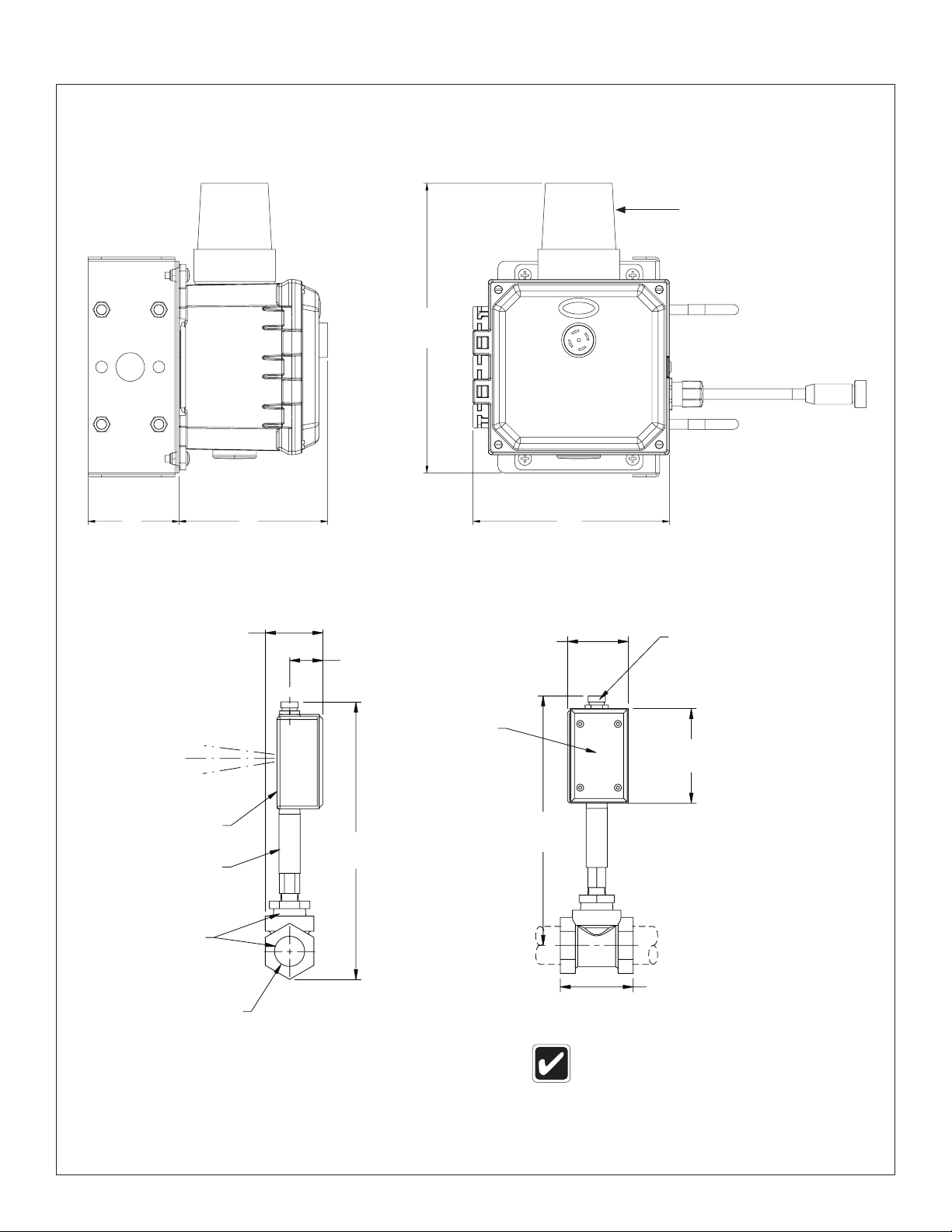
S19-323 Components
Signal Light
Type-3R Shown
(Standard)
10-3/4"
(273mm)
3-3/8"
(86mm)
Sensing
Blue
Black
¾" NPT Hub,
Plugged
Brass
Adapter
and Tee
1/2" (eyewash)
or 1-1/4" (drench
shower) NPT Inlet
and Outlet
2-7/8"
(73mm)
Remote
Red
Brass
Sensor
Body
5-1/2"
(140mm)
1-5/8"
(41mm)
13-13/16"
(351mm)
NEMA 3R
Junction Box
and Cover
3" (76mm)
12-3/8"
(315mm)
7-5/16"
(185mm)
Electrical Quick
Disconnect Male
4-11/16"
(119mm)
2-3/8" (60mm) for
eyewash or
3-9/16" (91mm) for
drench shower
System is prewired. Installer connects
ONLY ground black and white wires.
4
11/21/2017 Bradley • 215-1846 Rev. C; ECN 17-05-068
Installation S19-323, S19-324
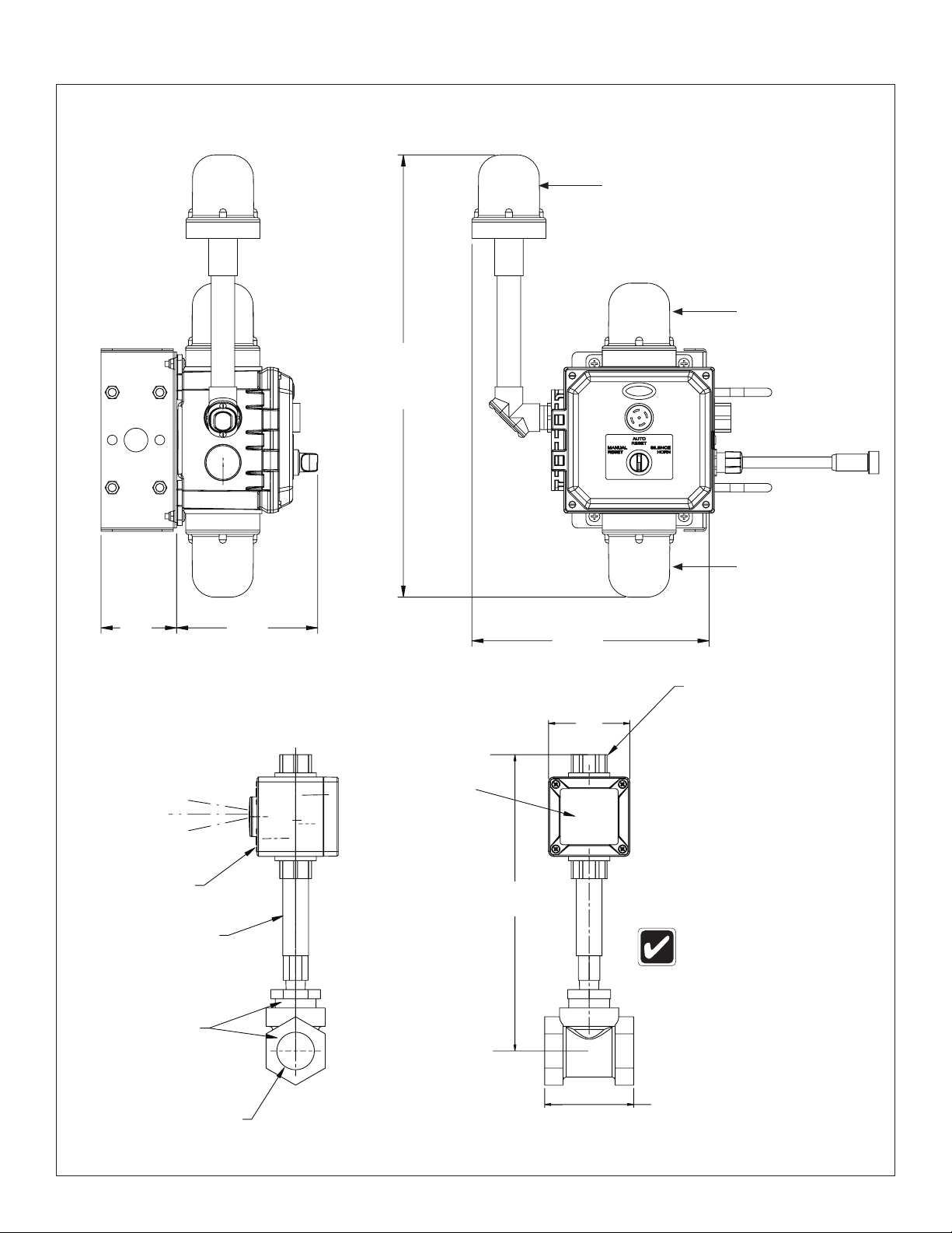
S19-324 Components
Beacon Light
Type-4X Shown
(Optional)
Signal Light
Type-4X Shown
(Standard)
19-3/4"
(501mm)
3-3/8"
(86mm)
Remote
Sensing
Red
Blue
Black
¾" NPT Hub,
Plugged
Brass
Sensor
Body
6-5/16"
(160mm)
Area Light
Type-4X Shown
(Optional)
10-9/16"
(269mm)
Electrical Quick
Disconnect Male
3-5/16"
(84mm)
NEMA 4X
Junction Box
and Cover
12-1/16"
(306mm)
System is prewired. Installer
connects ONLY ground black
and white wires.
Brass
Adapter
and Tee
1/2" (eyewash)
or 1¼" (drench
shower) NPT Inlet
and Outlet
Bradley • 215-1846 Rev. C; ECN 17-05-068 11/21/2017
2-3/8" (60mm) for
eyewash or
3-9/16" (91mm) for
drench shower
5
 Loading...