

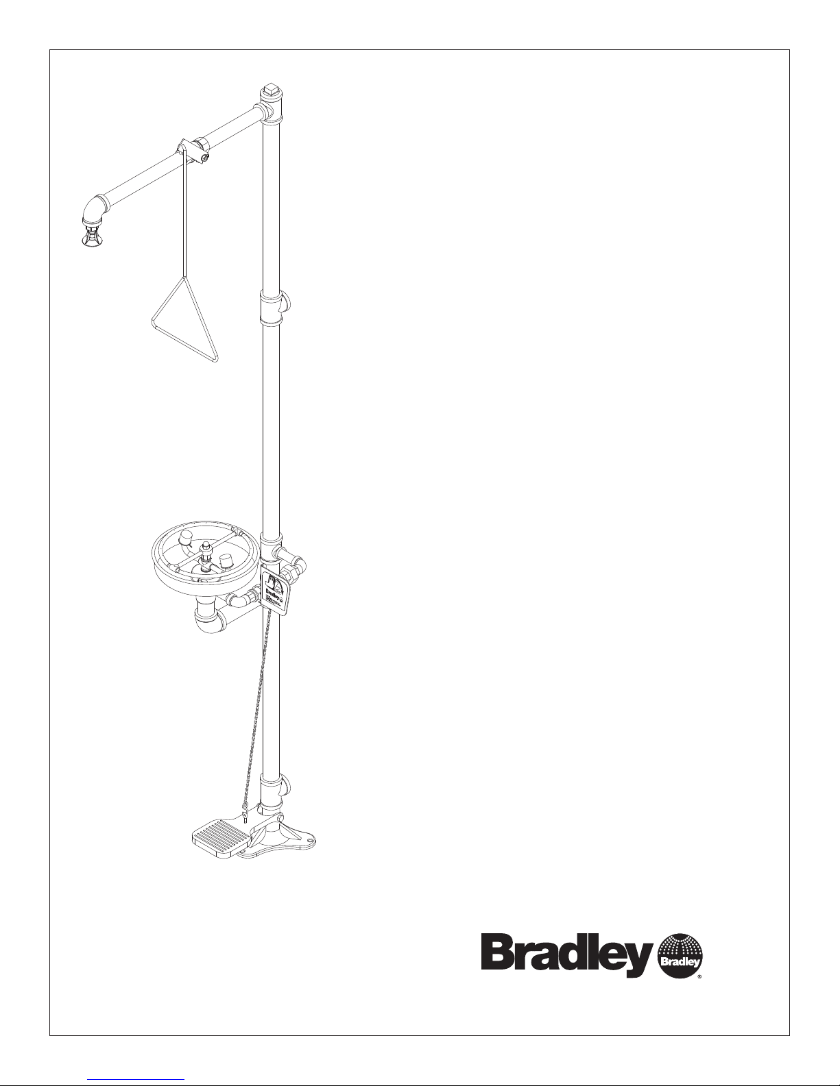
Bradley S19-310SS Installation Instructions Manual
Installation
S19-310SS
Combination Drench Shower and
Eyewash
Combiné douche oculaire
Combinación de ducha de
aspersión y lavaojos
Table of Contents
Pre-Installation Information . . . . . . . . . . . . . . 2
Installation Instructions. . . . . . . . . . . . . . . . . . 3
Assembly of Components . . . . . . . . . . . . . . . 4
Parts List . . . . . . . . . . . . . . . . . . . . . . . . . . . . 5
Table des matières
Avant l’installation. . . . . . . . . . . . . . . . . . . . . . 6
Instructions d’installation . . . . . . . . . . . . . . . . 7
Assemblage des composantes . . . . . . . . . . . 8
Liste des pièces . . . . . . . . . . . . . . . . . . . . . . . 9
Contenido
Información previa a la instalación. . . . . . . . 10
Instrucciones de instalación. . . . . . . . . . . . . 11
Armado de los componentes . . . . . . . . . . . . 12
Lista de piezas . . . . . . . . . . . . . . . . . . . . . . . 13
215-533 Rev. W; ECM 10-05-022
© 2010 Bradley Corporation
Page 1 of 13 3/15/10
P.O. Box 309, Menomonee Falls, WI USA 53052-0309
PHONE 800.BRADLEY (800.272.3539) FAX 262.251.5817
bradleycorp.com
S19-310SS Installation
IMPORTANT
Installation
R
1
5
0
3
I 5
W
,
s
ll
a
F
e
e
n
o
R
P
m
o
U
n
Z
e
H
M
,
IC
9
L
0
K
T
3
E
N
E
x
E
eek an
o
H
W
C
B
H
.
Ö
h w
C
O
c
E
.
W
A
P
R
I
T
E
s immed
S
A
T
I
D
1
Testbe
N
A
T
e(s) ea
U
Ä
M
R
S
O
I
alv
h im
E
D
H
eglic
T
B
G
alfunction
tlic
E
S
T
E
S
H
I
S
E
y m
hen
T
A
E
hrift. J
I
perate v
S
D
öc
S
E
nnem
'il y
ntersc
Test-o
eport an
m
R
as. S
fonctio
Ventil(e) w
t im
durch U
e en b
Test le
rappor
sign
un
Date
Datum
Date
114-051
.
N
E
F
Ü
belo
d sign
.
y
el
prüfen,
iat
b
g s
trie
törun
es
he S
alv
e c
es v
ent d
ent.
à quelqu
édiatem
Signed
Unterschrift
Signe
.
w
ätigt
est
elden.
b
aine et
t m
as fait
or
a p
of
e v
chaque sem
se qui n
ho
Date
Date
Date
P.O. BOX 309, MENOMONEE FALLS, WI 53052-0309 USA
TEL: 1-800-BRADLEY FAX: (262-251-5817)
Read this installation manual completely to ensure proper installation, then file it
with the owner or maintenance department. Compliance and conformity to drain
requirements and other local codes and ordinances is the responsibility of the installer.
Separate parts from packaging and make sure all parts are accounted for before
Packing List
•
•
•
THIS
SIDE
UP
discarding any packaging material. If any parts are missing, do not begin installation
•
until you obtain the missing parts.
Flush the water supply lines before beginning installation and after installation is
complete. Test the unit for leaks and adequate water flow. Main water supply to the
eyewash should be “ON” at all times. Provisions shall be made to prevent unauthorized
shutoff.
The ANSI Z358.1 standard requires an uninterruptible supply of flushing fluid at a
minimum 30 PSI (0.21 MPa) flowing pressure. Flushing fluid should be tepid per ANSI
Z358.1.
Signed
Signed
Signed
The inspection and testing results of this equipment should be recorded weekly to verify
proper operation. This equipment should be inspected annually to ensure compliance
with ANSI Z358.1.
Workers who may come in contact with potentially hazardous materials should be
trained regarding the placement and proper operation of emergency equipment per ANSI
http://www.bradleycorp.com
Z358.1.
For questions regarding the operation or installation of this product, visit www.
bradleycorp.com or call 1-800-BRADLEY.
Product warranties and service parts information may also be found under ”Products”
on our web site at www.bradleycorp.com.
2
3/15/10 Bradley Corporation • 215-533 Rev. W; ECM 10-05-022
Installation S19-310SS
Installation
Supplies Required:
• (3) 3⁄8" floor anchors and bolts
• Pipe sealant
• Piping to 1¼" NPT water supply inlet and 1¼" NPT
drain outlet on unit
• Adequate supply pipe supports
• Minimum 4" (102mm) drain to accommodate 30
gallons (115 liters) per minute discharge for shower
waste
• OPTIONAL: sign-mounting hardware
NOTE: Local codes may require the installation
of a backfl ow prevention valve to complete proper
installation. Compliance with local codes is the
responsibility of the installer. Valve must be tested
annually to verify that it is functioning properly. Backfl ow
prevention valves are not included with the fi xture and
may be supplied by the contractor or purchased from
Bradley Corporation.
Step 1: Secure base to floor
1. Install three suitable anchors (supplied by installer)
3
for
⁄8" bolts in the floor.
2. Bolt the base to the floor anchors using 3/8" bolts
(supplied by installer).
Step 2: Assemble components
1. Assemble the remaining unit components as
shown on page 4.
• Apply pipe sealant (by installer) to all male-
threaded pipe joints.
• Use the rubber grip pad provided or a strap
wrench around pipes when tightening to prevent
marring. Place the grip pad on the pipe, then
put the wrench over the grip pad and turn the
pipe with the wrench.
• When connecting the steel chain, first connect
the chain to the “S” hook on the foot treadle.
Then, with the foot treadle raised up, straighten
the chain and connect a link to the “S” hook on
the valve handle. Make sure the chain is pulled
tight. The length of chain will vary.
• The bottom edge of the showerhead should be
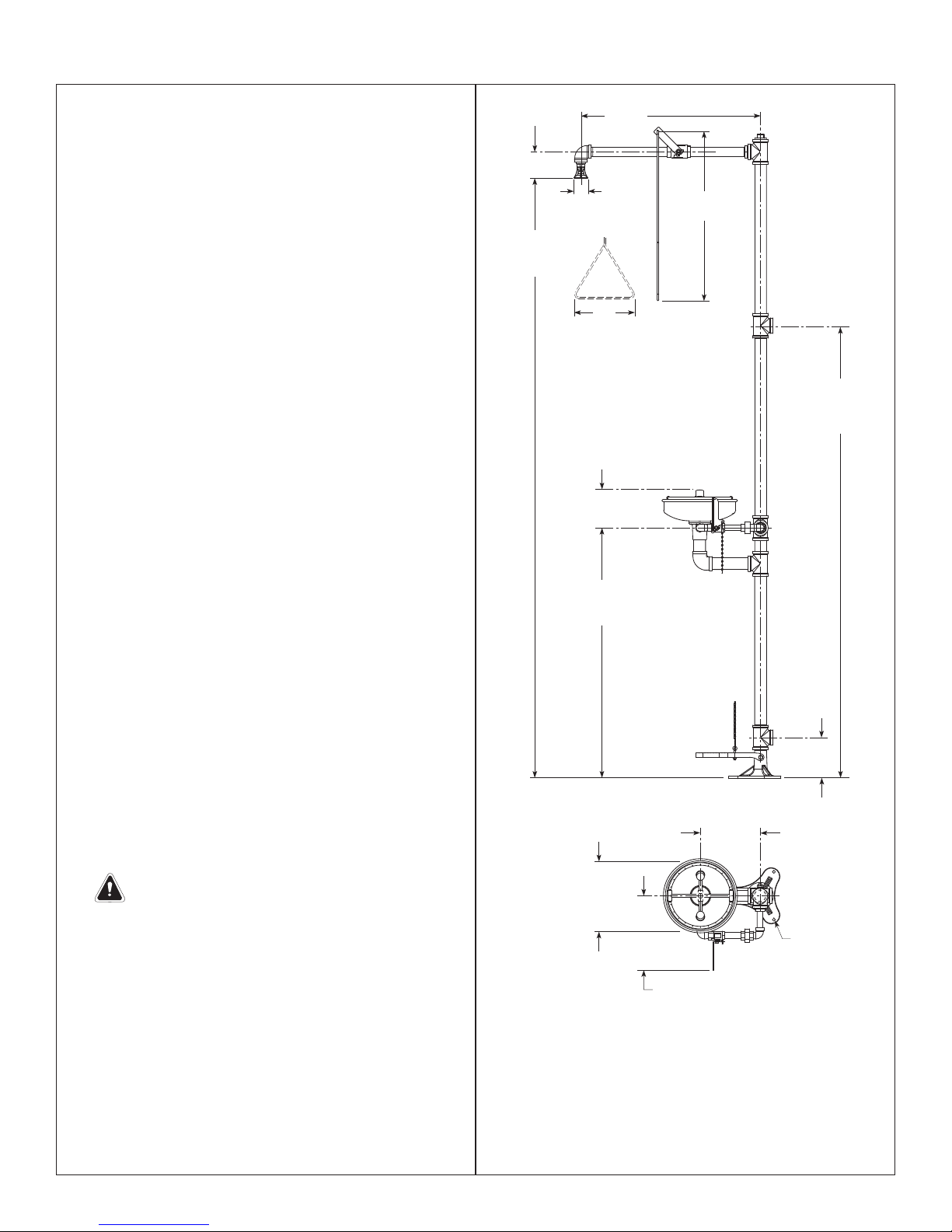
86¾" (2203mm) from the floor.
Step 3: Connect water supply
3¾" (95mm)
86¾"
(2203mm)
to Floor
(670mm)
Ø 2"
(51mm)
9"
(229mm)
6"
(152mm)
3
⁄8"
36
(924mm)
263⁄8"
25½"
(648mm)
66"
(1676mm)
to Floor
6"
(152mm)
9"
(229mm)
IMPORTANT: Do not rely on Bradley’s
Combination Unit to support supply piping.
1. Connect water supply piping to 1¼" NPT inlet
on unit (piping by installer). Provide adequate
supports (by installer) for supply pipe using pipe
hangers or other means.
2. Connect drain piping to 1¼" NPT drain outlet on
unit (piping by installer).
3. Hang the safety sign from the unit with the curtain
hooks provided (or mount it to the wall using signmounting hardware by installer).
Bradley Corporation • 215-533 Rev. W; ECM 10-05-022 3/15/10
Ø 10¾"
(273mm)
Ø 9" (229mm)
Flange with (3) Ø
(10mm) Holes on
Ø 8" (203mm) Bolt
10½"
(267mm)
Circle
Top View From Bowl
NOTE: All dimensions assume standard thread
engagement. Variations in manufacturing allow for
+/- 1⁄8" (3mm) per threaded joint. To fi nd the tolerance
of a dimension, add the number of thread joints in
between a dimension and multiply it by 1⁄8" (3mm).
3
⁄8"
3
S19-310SS Installation
P.O. BOX 309, MENOMONEE FALLS, WI 53052-0309 USA
TEL: 1-800-BRADLEY FAX: (262-251-5817)
http://www.bradleycorp.com
114-052
Assembly of Components
NOTE: If tee (Item 2) is used as a supply
inlet, use plug (Item 6) on tee (Item 2)
6
2
Optional 1-1/4" NPT
Supply Inlet (best for
rigid support)
25.7
25.6
25.5
25.4
2
1-1/4" NPT
Supply Inlet
25.12
25.11
25.10
5
25.9
25.8
Flow
control
this end
2
13
12
13.1
11
7
9
9.1
8
3
9.2
9.11
10
14
27
P.O. Box 309, Menomonee Falls, WI 53051
TEST THIS UNIT EACH WEEK
DIESES GERÄT 1ST WÖCHENTLICH ZU PRÜFEN.
ESSAI HEBDOMADAIRE
Test-operate valve(s) each week and sign below.
Report any malfunctions immediately.
Ventil(e) wöchentlich im Testbetrieb prüfen, bestätigt
durch Unterschrift. Jegliche Störung sofort melden.
Test le fonctionnement des valves chaque semaine et
signe en bas. S'il y à quelque chose qui ne va pas fait
un rapport immédiatement.
Date
Signed
Datum
Unterschrift
Date
Signe
P.O. BOX 309, MENOMONEE FALLS, WI 53052-0309 USA
TEL: 1-800-BRADLEY FAX: (262-251-5817)
http://www.bradleycorp.com
114-052
Date Signed
Date
Date
28
R
Signed
Signed
NOTE: Items 9.1–9.2 come preassembled as Item 9.
Items 25.1–25.12 come preassembled as Item 25.
25
25.3
25.2
25.1
24
23
22
17
19
1-1/4" NPT
Drain Outlet
15
16
17
18
20
16
21
4
30
20.1
2
26.1
3
4
3/15/10 Bradley Corporation • 215-533 Rev. W; ECM 10-05-022
26.3
26.2
26.1
26.6
26.5
26.7
26.8
2
1
26.4
 Loading...