

Bradley S19-210FW Installation Manual
Installation
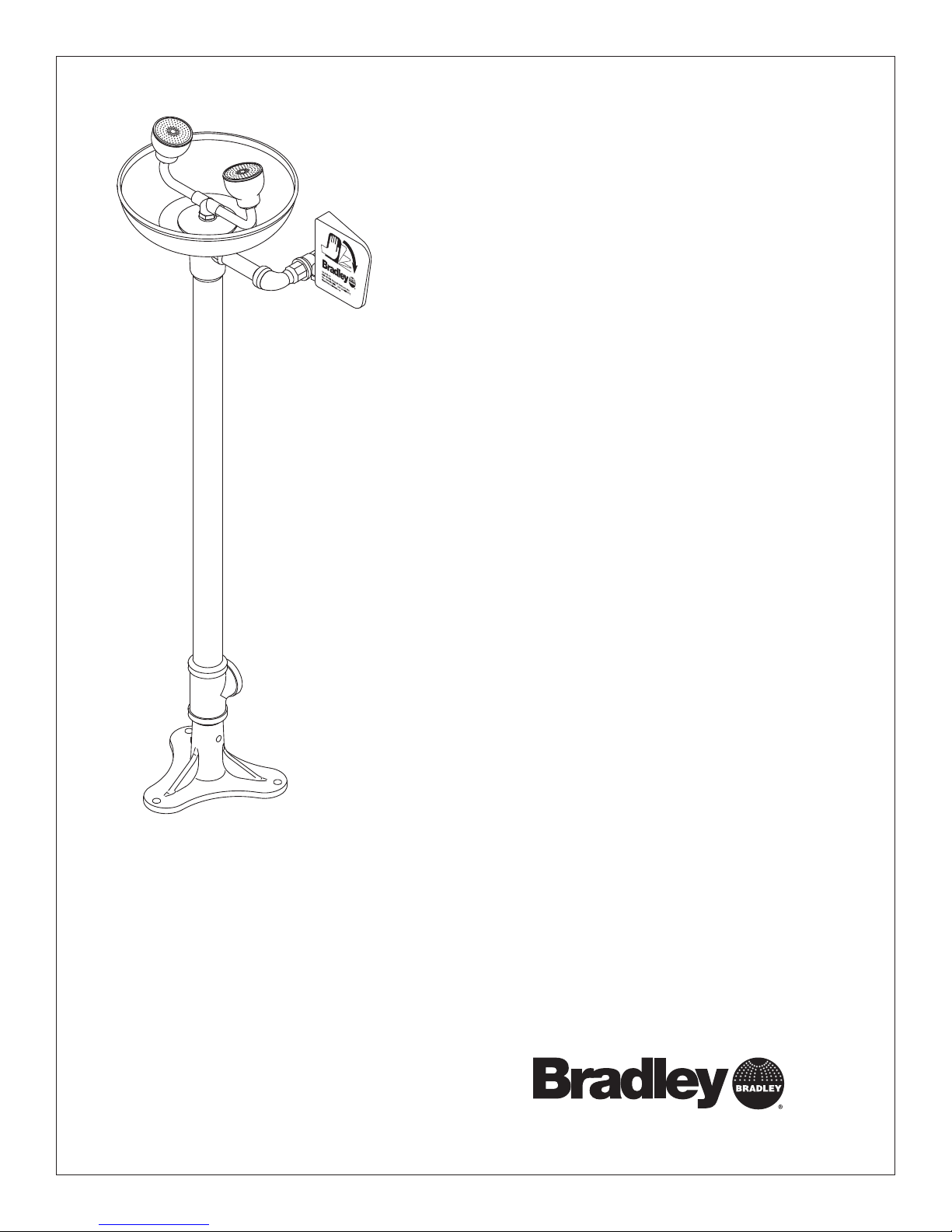
S19-210FW
Pedestal-Mounted Eye/Face Wash
Douche oculaire/faciale sur pied
Lavaojos/rostro montado en
pedestal
Table of Contents
Pre-Installation Information . . . . . . . . . . . . . . . . . . . 2
Installation Instructions . . . . . . . . . . . . . . . . . . . . . . 3
Assembly of Components . . . . . . . . . . . . . . . . . . . . 4
Parts List . . . . . . . . . . . . . . . . . . . . . . . . . . . . . . . . . 4
Table des matières
Avant l’installation . . . . . . . . . . . . . . . . . . . . . . . . . . 5
Instructions d’installation . . . . . . . . . . . . . . . . . . . . . 6
Assemblage des composantes . . . . . . . . . . . . . . . . 7
Liste des pièces . . . . . . . . . . . . . . . . . . . . . . . . . . . . 7
Contenido
Información previa a la instalación . . . . . . . . . . . . . 8
Instrucciones de instalación. . . . . . . . . . . . . . . . . . . 9
Montaje de los componentes. . . . . . . . . . . . . . . . . 10
Lista de piezas. . . . . . . . . . . . . . . . . . . . . . . . . . . . 10
215-155FW Rev. G; ECM 08-539
© 2009 Bradley Corporation
Page 1 of 10 6/9/09
P.O. Box 309, Menomonee Falls, WI USA 53052-0309
PHONE 1-800-BRADLEY FAX (262) 251-5817
bradleycorp.com
S19-210FW Installation
WARNING
Installation
R
1
5
0
3
I 5
W
,
s
ll
a
F
e
e
n
o
R
P
m
o
U
n
Z
e
H
M
,
IC
9
L
0
K
T
3
E
N
E
x
E
eek an
o
H
W
C
B
H
.
Ö
h w
C
O
c
E
.
W
A
P
R
I
T
E
s immed
S
A
T
I
D
1
Testbe
N
A
T
e(s) ea
U
Ä
M
R
S
O
I
alv
h im
E
D
H
eglic
T
B
G
alfunction
tlic
E
S
T
E
S
H
I
S
E
y m
hen
T
A
E
hrift. J
I
perate v
S
D
öc
S
E
nnem
'il y
ntersc
Test-o
eport an
m
R
as. S
fonctio
Ventil(e) w
t im
durch U
e en b
Test le
rappor
sign
un
Date
Datum
Date
114-051
.
N
E
F
Ü
belo
d sign
.
y
el
prüfen,
iat
b
g s
trie
törun
es
he S
alv
e c
es v
ent d
ent.
à quelqu
édiatem
Signed
Unterschrift
Signe
.
w
ätigt
est
elden.
b
aine et
t m
as fait
or
a p
of
e v
chaque sem
se qui n
ho
Date
Date
Date
P.O. BOX 309, MENOMONEE FALLS, WI 53052-0309 USA
TEL: 1-800-BRADLEY FAX: (262-251-5817)
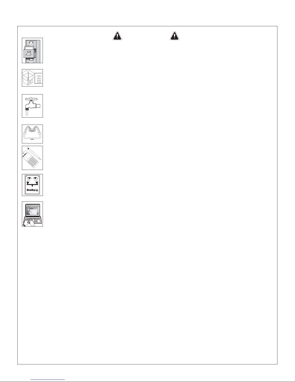
Read this installation manual completely to ensure proper installation, then file it
with the owner or maintenance department. Compliance and conformity to drain
requirements and other local codes and ordinances is the responsibility of the installer.
Separate parts from packaging and make sure all parts are accounted for before
Packing List
•
•
•
THIS
SIDE
UP
discarding any packaging material. If any parts are missing, do not begin installation
•
until you obtain the missing parts.
Flush the water supply lines before beginning installation and after installation is
complete. Test the unit for leaks and adequate water flow. Main water supply to the
eye/face wash should be “ON” at all times. Provisions shall be made to prevent
unauthorized shutoff.
The ANSI Z358.1 standard requires an uninterruptible supply of flushing fluid at a
minimum 30 PSI (0.21 MPa) flowing pressure. Flushing fluid should be tepid per ANSI
Z358.1.
Signed
Signed
Signed
The inspection and testing results of this equipment should be recorded weekly
to verify proper operation. This equipment should be inspected annually to ensure
compliance with ANSI Z358.1.
Workers who may come in contact with potentially hazardous materials should be
trained regarding the placement and proper operation of emergency equipment per
http://www.bradleycorp.com
ANSI Z358.1.
For questions regarding the operation or installation of this product, visit www.
bradleycorp.com or call 1-800-BRADLEY.
Product warranties and service parts information may also be found under ”Products”
on our web site at www.bradleycorp.com.
2
6/9/09 Bradley Corporation • 215-155FW Rev. G; ECM 08-539
Installation S19-210FW
Installation
Supplies Required:
• (3) 3⁄8" floor anchors and bolts
• Pipe sealant
• Piping to ½" NPT water supply inlet
• Piping to 1¼" NPT drain outlet
• Sign-mounting hardware
NOTE: Local codes may require the installation of
a backfl ow prevention valve to complete proper
installation. Compliance with local codes is the
responsibility of the installer. Valve must be tested
annually to verify that it is functioning properly.
Backfl ow prevention valves are not included with
the fi xture and may be supplied by the contractor
or purchased from Bradley Corporation.
3
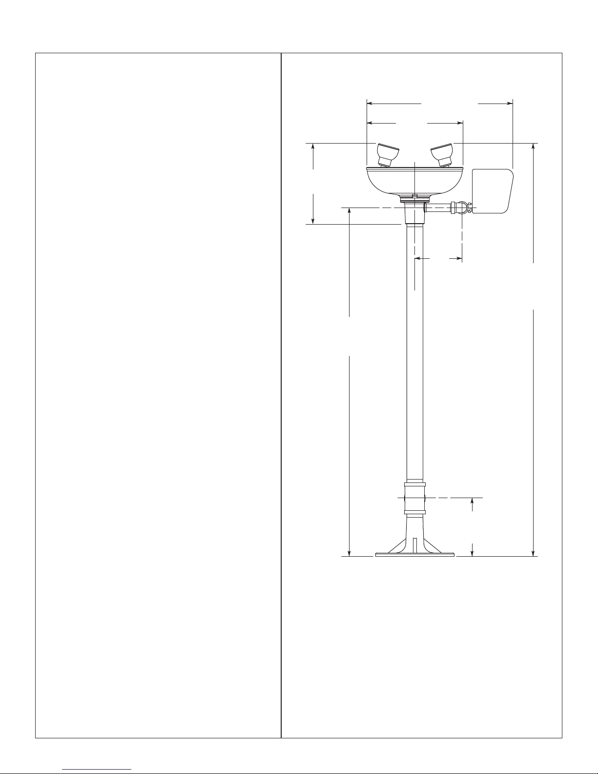
⁄8"
8
(212mm)
(254mm)
15½" (394mm)
Ø 10"
Step 1: Secure base to floor
1. Install three suitable anchors (supplied by
installer) for
3
⁄8" bolts in the floor.
2. Bolt the base to the floor anchors using
bolts (supplied by installer).
Step 2: Assemble eye/face wash
1. Assemble eye/face wash components as
shown on page 4
• Apply pipe sealant (supplied by installer) to
all male-threaded pipe joints.
• Use the rubber grip pad provided or a
strap wrench around pipes when tightening
to prevent marring the Bradtect®
protective, safety yellow coating. Place the
grip pad on the pipe, then put the wrench
over the grip pad and turn the pipe with
the wrench.
.
Step 3: Connect water supply
1. Connect the water supply piping (supplied by
installer) to the ½" NPT inlet on the eye/face
wash.
2. Connect the drain piping (supplied by
installer) to the 1¼" NPT drain outlet on the
eye/face wash.
3. Mount the safety sign to the wall using signmounting hardware (supplied by installer).
5¼"
(133mm)
3
⁄8"
36"
(914mm)
to Bottom
of Base
6"
(152mm)
5
⁄8"
42
(1082mm)
to Bottom
of Base
Bradley Corporation • 215-155FW Rev. G; ECM 08-539 6/9/09
NOTE: All dimensions assume standard thread engagement.
Variations in manufacturing allow for +/- 1⁄8" (3mm) per
threaded joint. To find the tolerance of a dimension,
add the number of thread joints in between a
dimension and multiply it by 1⁄8" (3mm).
3
 Loading...