

Bradley EFX8/S19-2000 Series, S19-2000EFX Series, S19-2000EFX, S19294JB, S19-2000 Installation Instructions Manual
...Page 1
Installation
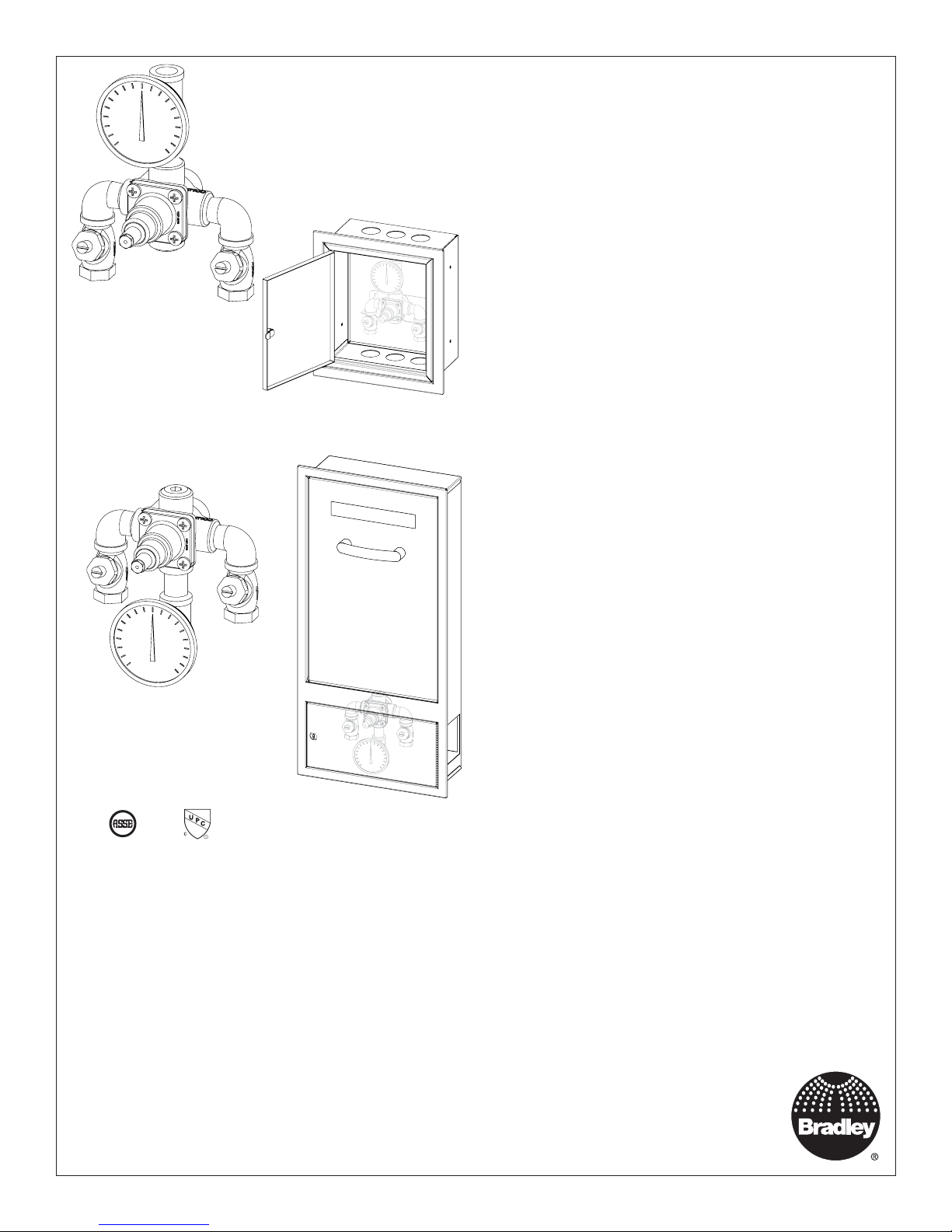
EFX8/S19-2000,
S19-2000EFX Series
Thermostatic Mixing Valve
S19-2000
S19-2000EFX
ASSE 1071 & cUPC Certified
®
S19294JB, S19294JBT
(Cabinet Only)
S19294JB, S19294JBT
(Cabinet Only)
with Optional Cabinet
Robinet thermostatique
mélangeur avec cabinet facultatif
Válvula mezcladora termostática
con armario opcional
Table of Contents
Supplies Required .......................................................................... 3
Optional Equipment Installation ..................................................... 3
Dimensions..................................................................................... 4
Installation Instructions ................................................................... 5
Troubleshooting .............................................................................. 7
Sommaire
Fournitures requises .................................................................... 11
Installation de l’équipement optionnel ...........................................11
Dimensions................................................................................... 12
Instructions relatives à l’installation .............................................. 13
Dépannage ................................................................................... 15
Tabla de contenidos
Materiales necesarios .................................................................. 19
Instalaciones de equipos opcionales ........................................... 19
Dimensiones................................................................................. 20
Instrucciones de instalación ......................................................... 21
Solución de problemas ................................................................. 23
Inlet Connections: 1/2" NPT
Outlet Connection: 1/2" NPT
Temperature Range: 65° – 90° F
Maximum Pressure: 125 PSI
Inlet Temperature Hot: 120° – 180° F
Inlet Temperature Cold: 33° – 80° F
Minimum Temperature Differential
(from valve set point): 20° F
Flow at 30 psi: 7.3 gpm
Minimum Cold Water Bypass at 30 psid: 5.6 gpm
Minimum Flow: 1.5 gpm
Maximum Flow with Cold Water Shut-Off: 0.5 gpm
215-1291 Rev. S; ECN 17-09-009
© 2017 Bradley
Page 1 of 25 12/7/2017
Raccords d’arrivée : 1/2 po NPT
Raccord de sortie : 1/2 po NPT
Plage de température : 65 – 90 °F
Pression maximum : 125 lb/po
Température d’arrivée, eau chaude : 120 – 180 °F
Température d’arrivée, eau froide : 33 – 80 °F
Différence de température minimum
(à partir de valeur de consigne de robinet) : 20 °F
Débit à 30 psi : 7.3 gpm
Dérivation d’eau froide minimum à 30 psid : 5.6 gpm
Débit minimum : 1.5 gpm
Débit maximum avec arrêt d’eau froide : 0.5 gpm
2
Menomonee Falls, WI 53052 USA
800 BRADLEY (800 272 3539)
Conexiones de entrada: NPT de 1/2 pulg.
Conexión de salida: NPT de 1/2 pulg.
Rango de temperaturas: 65 – 90 °F
Presión máxima: 125 PSI
Temperatura de entrada, caliente: 120 – 180 °F
Temperatura de entrada, fría: 33 – 80 °F
Diferencial de temperatura mínima
(desde el punto de ajuste de la válvula): 20 °F
Flujo a 2,1 bar: 7.3 gpm
Derivación mínima de agua fría a 2,1 bar: 5.6 gpm
Flujo mínimo: 1.5 gpm
Flujo máximo con retención de agua fría: 0.5 gpm
P.O. Box 309
+1 262 251 6000
bradleycorp.com
Page 2

S19-2000, S19-2000EFX Installation
WARNING
Failure to comply with proper installation and maintenance instructions could contribute to the valve failure
resulting in severe bodily injury including scalding, chilling, and/or death depending upon system water
pressure changes and/or supply water temperature changes.
Use this thermostatic mixing valve in accordance with ASSE standard 1071. Operation of emergency
thermostatic mixing valves and fixtures must be tested weekly per ANSI/ISEA Z358.1. This valve does not
provide protection from pipe freezing.
Output temperature of the valve must be checked and adjusted at initial installation and on a quarterly basis.
Make sure that all water supply lines have been flushed and then completely turned off before beginning
installation. Debris in supply lines can cause valves to malfunction.
If shut-off valves are installed for maintenance purposes, provisions shall be made to prevent unauthorized
shut-off.
NOTICE
Regular checking and cleaning of the valve’s internal components and check stops is necessary for
maximum life and proper product function. Periodic Inspection and Yearly Maintenance by a licensed
contractor is required. Corrosive water conditions, and/or unauthorized adjustments or repairs could render
the valve ineffective for its intended service. Frequency of cleaning and inspection depends upon local
water conditions.
IMPORTANT
Read this entire installation manual to ensure proper installation. When finished with the installation, file
this manual with the owner or maintenance department. Compliance and conformity to local codes and
ordinances is the responsibility of the installer.
Consult local building and plumbing codes prior to installation. Should these codes differ from the
information in the Manual, follow the local codes. Inquire with governing authorities for additional local
requirements.
Valve shall be accessible for testing, adjusting and maintenance in the installed position.
Separate parts from packaging and make sure all parts are accounted for before discarding packaging
material. If any parts are missing, do not begin installation until you obtain the missing parts.
Product warranties may be found under “Products” on our web site at bradleycorp.com.
2 12/7/2017 Bradley • 215-1291 Rev. S; ECN 17-09-009
Page 3
Installation S19-2000, S19-2000EFX
Supplies recommended for installation
• Lockable shut-off on the outlet if tempered water is supplied to one or more emergency fixtures
• Lockable shut-off on the inlets/supplies
• (6) 1/4" wall anchors and fasteners for surface-mounted cabinet
• (4) 1/4" fasteners (and wall anchors, if necessary) for recess-mounted cabinet
• Unions on all connections to facilitate removal of valve
Tools required for temperature adjustment
• 5/64" Allen wrench
• Blade screwdriver
1
Install Optional Cabinet (If not installing cabinet, skip to Step 2)
If installing S19-2000EFX into Dropdown Eyewash Cabinet S19294JB,
S19294JBT, please see mounting instructions supplied with cabinet.
Recessed Cabinet:
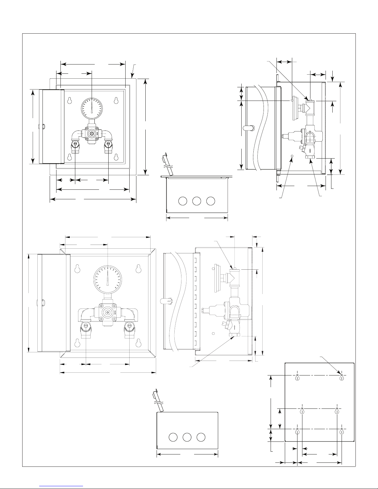
1. Rough-in wall opening 11-1/2" W x 13" H.
2. Insert the cabinet and secure to wall with four 1/4"
fasteners properly anchored (supplied by installer.)
3. Install two anchors and screws through the valve bracket
in back of the cabinet into a secure brace (supplied by
installer) or into wall. This will support the valve.
4. Install the valve nipples and one-half of the union ball
valve using pipe sealant or teflon tape. Install the other
half of the union ball valve onto inlet and outlet pipe.
5. Insert the valve into the bracket in the cabinet (right
side goes in first). Continue with the valve installation
procedure.
6. Position the wall flange tight to the wall and caulk in
place.
Surface-Mounted Cabinet:
1. Measure and mark the cabinet mounting hole
locations at the dimensions shown on next
page. Install six 3/8" wall anchors (supplied by
installer).
2. Position the cabinet onto the wall and secure
into place with six 3/8" wall fasteners (supplied
by installer).
3. Install the valve nipples and one-half of the
union ball valve using pipe sealant or teflon tape.
Then install the other half of the union ball valve
onto the inlet and outlet piping.
4. Insert the valve into the bracket in the cabinet
(right side of the valve goes in first). Continue
with the valve installation procedure.
Bradley • 215-1291 Rev. S; ECN 17-09-009 12/7/2017 3
Page 4
S19-2000, S19-2000EFX Installation
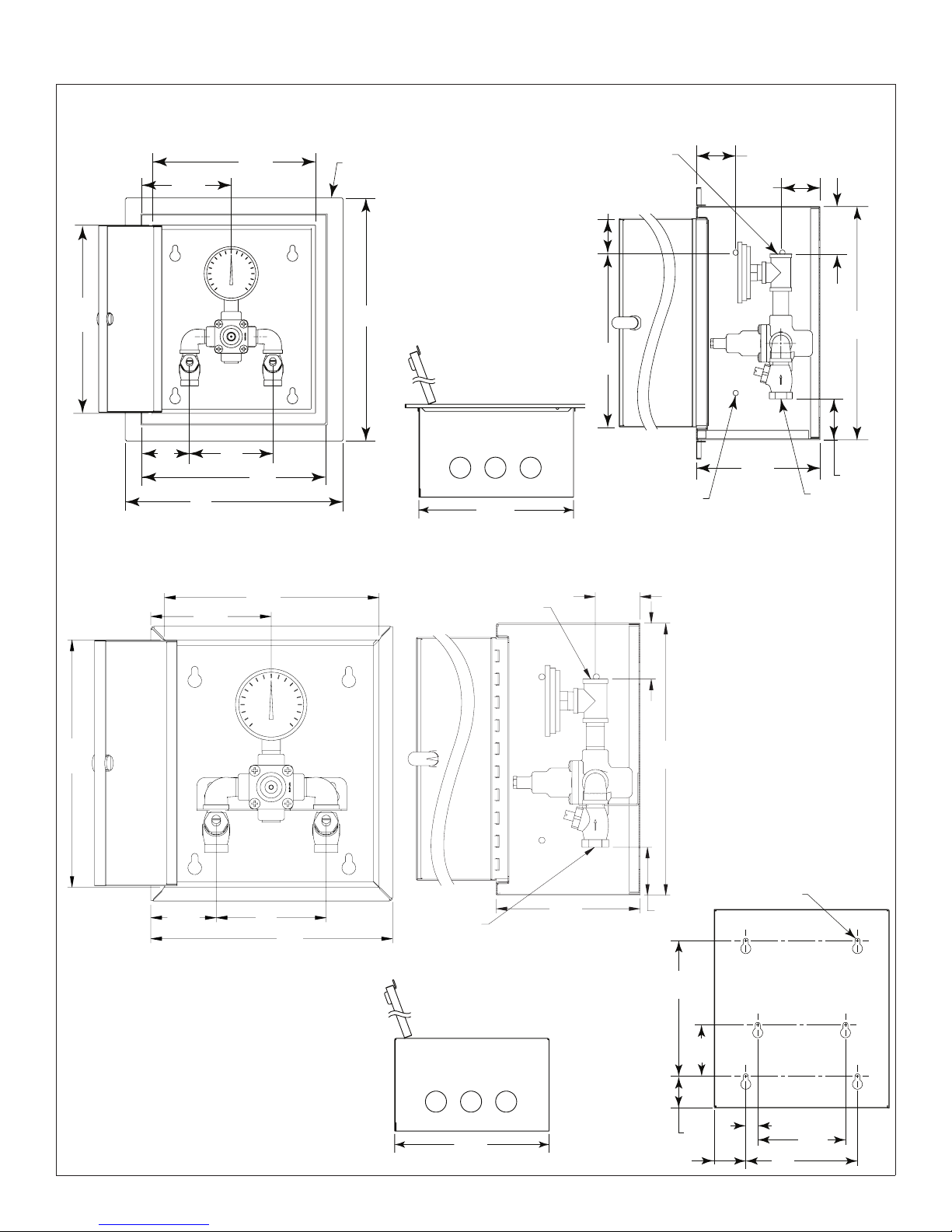
Optional Recessed Cabinet
11¼"
(286)
Door
Front View
(76)
5³⁄₈"
(137)
3"
13"
(330)
5"
(127)
9¾"
(248)
Door
11"
(279)
Box
Wall
Flange
14½"
(368)
Optional Surface-Mounted Cabinet
9¾"
(248)
5½"
(140)
Door
Bottom View
11"
(279)
½" NPT
Outlet
2½"
(64)
7-1/2"
(190)
2"
(51)
½" NPT
Outlet
⁹⁄₃₂" Dia. Holes
(4) each side,
(8) Total
Side View
2"
(51)
(51)
6½"
(165)
(mm)
2"
2½"
(64)
12½"
(318)
2¼"
(57)
½" NPT
Inlets
11¼"
(286)
Door
(76)
2½"
(64)
12½"
(318)
Mounting Hole
Locations
⁵⁄₁₆" (8) Dia. Holes
3"
5"
(127)
11"
(279)
Box
½" NPT
Inlets
6½"
(165)
2¼"
(57)
8½"
(216)
3¼"
(83)
(6) Total
4 12/7/2017 Bradley • 215-1291 Rev. S; ECN 17-09-009
11"
(279)
(51)
¾"
2"
(19)
(51)
2"
7"
(178)
5½"
(140)
Page 5
Installation S19-2000, S19-2000EFX
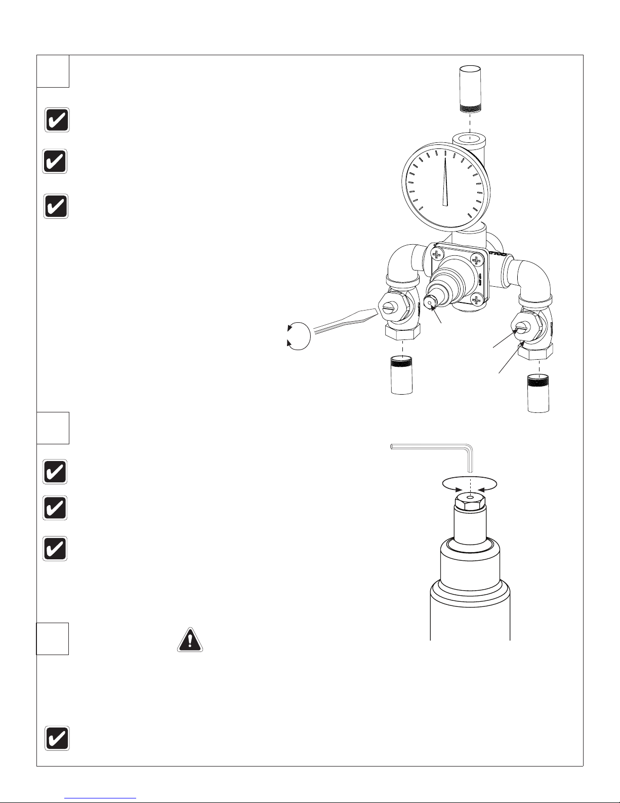
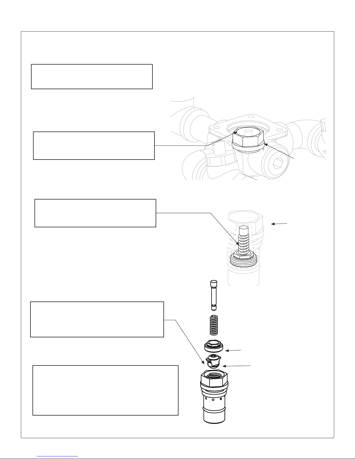
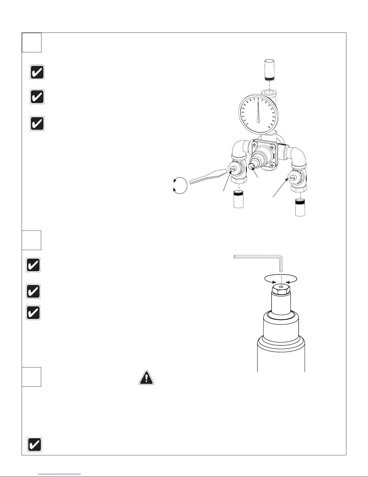
2
Connect Supply Lines and Install Thermometer
Check for leaks by pressurizing unit SLOWLY.
Check the temperature when approx. 3-5 gpm water flow
is reached (equivalent to one eye wash or face wash)
and adjust if necessary.
When the check stops are in the fully open (opera ting)
position, the stem will extend approximately 1/2" (13mm)
from the stem nut.
Open
Close
Hole In Cap
Tempered Water
(to Fixture)
Stem
3
4
S19-2000 Shown
Adjust Temperature with Water Running
Check the temperature when approximately 3 – 5 gpm
water flow is reached (equivalent to one eye wash).
No single emergency fixture supplied by this device shall
have a minimum flow rate less then 1.5 gpm.
This device must be checked for final temperature and adjusted as
necessary. The standard preset factory temperature setting is 85°F
(29°C) [the range of the valve is 65°F–90°F (18°C–32°C)]. Insert
Allen Wrench through the hole in the cap and into the set screw
to adjust. Consult proper medical and/or safety authorities for the
optimum temperature recommended for your particular application.
Test Unit
DO NOT SKIP THIS STEP!!!
HOT
5/64" Allen Wrench
Stem Nut
COLD
H
C
Shut the hot water supply off by closing hot water inlet valve or supply check valve. While the hot water supply is turned off, check
to make sure the cold water continues to flow. If the cold water is flowing properly, reopen the hot water supply.
Shut the cold water supply off by closing the cold water inlet valve or supply check valve. While the cold water supply is off, check
to make sure that the hot water flow has shut down to less then 0.5 gpm. If hot water is shut down, fully reopen cold water supply.
Test the system weekly (turn on the water supply and check for constant control of the desired set
temperature).
Bradley • 215-1291 Rev. S; ECN 17-09-009 12/7/2017 5
Page 6
S19-2000, S19-2000EFX Installation
5
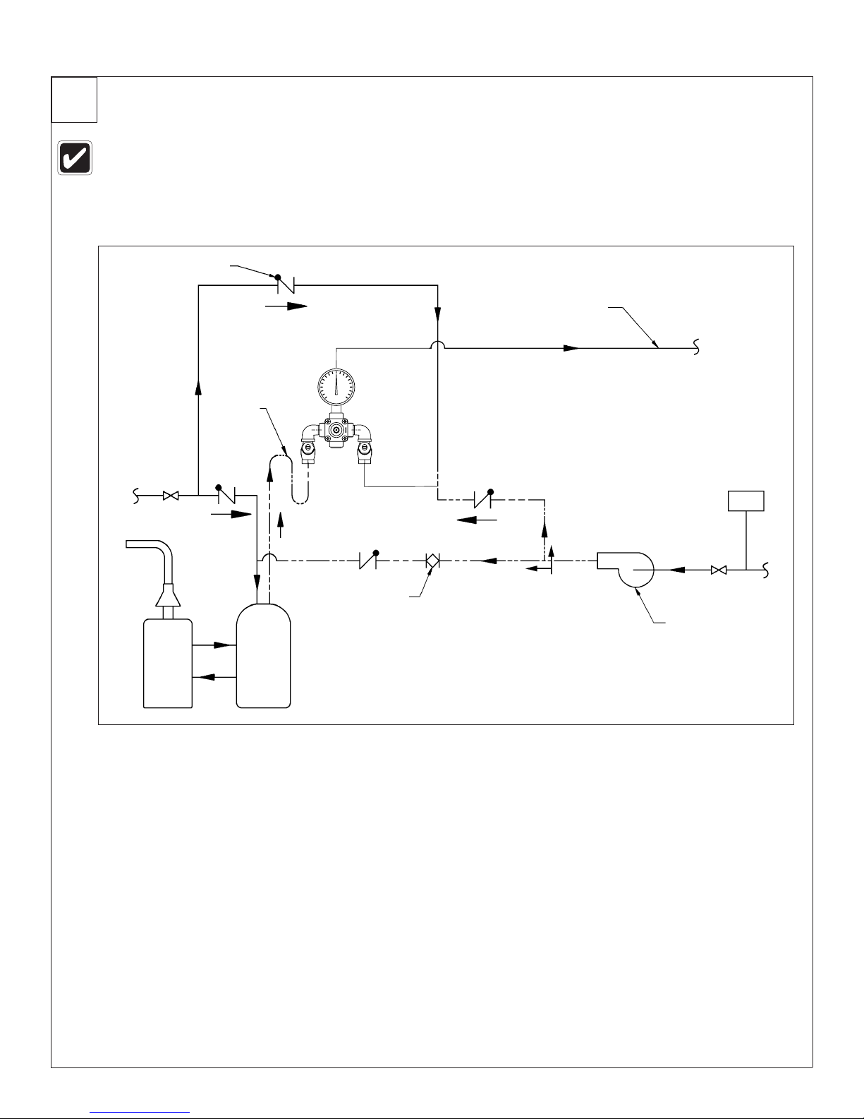
Optional Water Recirculation Setup
Recirculating the water in the system provides constant regulation of the water temperature. Flush the supply
lines thoroughly after completing installation. Close off all fixtures and label them as not available for use durin g
the recirculating process.
Check Valve
(Typ)
Cold
Water
COLD
Heat Trap
28" Drop
Tempered Water Flow
Temperature Switch
Recirculated
Tempered
Water
Recirculating Pump
Water
Heater
Storage
Tank
HOT
Return Flow
Balancing Valve (Typ)
1. Turn off the recirculating pump and turn on the water supply at emergency fixture (a water flow rate of 3 – 5 gpm is
required).
2. Let the water run through the system until a consistent temperature is obtained. If you do not obtain the required
temperature, refer to step #3 on previous page for temperature readjustment.
3. As soon as the water reaches the proper temperature, turn on the recirculating pump (make certain the proper system
temperature has been achieved before proceeding).
4. Check the water temperature at the return pump. If the temperature exceeds the appropriate level by 2°F, adjust the
temperature high-limit switch (this will turn off the pump). Wait until the return water temperature is 5°F below the
appropriate level and adjust the low-limit switch (this will turn the pump back on).
5. Open the balancing valve completely.
6. Turn off all fixtures and make sure there is no water running through the system (the cold inlet pipe should feel warm to the
touch).
7. Let the system run for 30 minutes or longer without water. If, after thirty minutes, the water temperature increases, you may
readjust the temperature by slowly closing the balancing valve until the appropriate temperature is reached.
6 12/7/2017 Bradley • 215-1291 Rev. S; ECN 17-09-009
Page 7
Installation S19-2000, S19-2000EFX
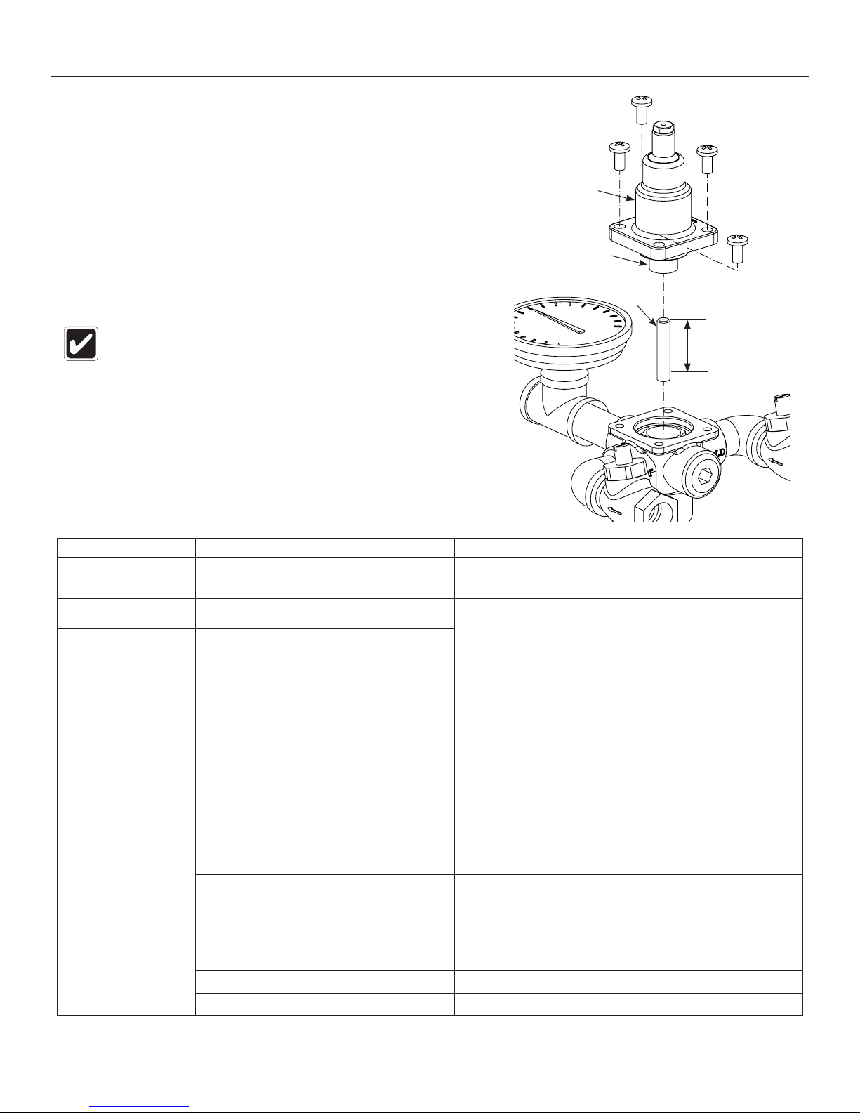
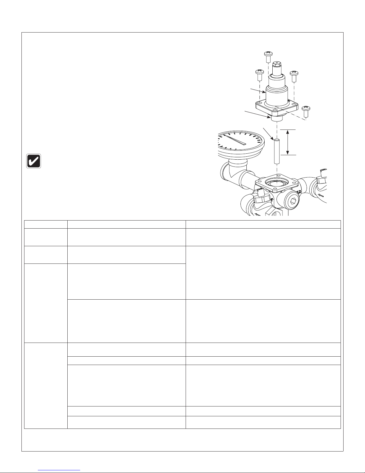
Troubleshooting Thermostatic Mixing Valve
Before attempting to troubleshoot the valve or disassemble the
components, check for the following:
• Stop/check valves are fully open (the slotted stem
extends approximately 1/2" from the stem nut) and that
all inlet and outlet shut-off valves are open
• Hot and cold inlet pipes are connected properly, and
that there are no cross-connectio ns or leaking stop/
check valves
• Water heater output is at least 20° F above the set
temperature.
Top Cap &
Thermostat
Thermostat
Bellows
5/16" Push
Rod
Be sure to close the appropriate shut-off valves
prior to disassembly of the valve and reopen the
valves after inspection and repair is complete.
Push Rod length
should extend
15/16" – 1-3/16"
into Bellows
Problem Cause Solution
External leaks in the system Either the NPT joints or the o-rings have been damaged. Replace the NPT joints and/or o-rings where necessary. For replacement
No hot water flow (cold water
flow only)
Limited water flow The inlet shut-off valve may be partially closed or there
Temperature fluctuation or
improper Temperature
The thermostat has failed and, subsequently, the safety
shut-off has engaged.
has been a significant decrease in water pressure.
Dirt and debris have collected on the check screen or
seat, limiting the movement of the stop and checks.
The stop and check sections of the valve do not move
freely.
Thermostat is slowly failing. Check Thermostat as described above, or replace.
Inlet supply line to the mixing valve is being shared by
other pieces of equipment that are used only periodically,
such as laundry appliances or washdown stations. It may
reduce the inlet pressure to the mixing valve to less than
3 PSI. The supply line size may not be large enough to
supply both the valve and the other appliances.
of o-rings, contact your Bradley representative and ask for O-Ring Seal Kit
(S65-170).
Inspect Thermostat:
1. Remove the top cap and thermostat.
2. Insert the 5/16" dia. push rod into the thermostat bellows.
3. Mark the length the push rod extends into the bellows (at room
temperature, with 10 lb. of force. the length should be approx. 15/16"
– 1-3/16").
4. If the push rod length is not in the proper range, the thermostat
must be replaced (it cannot be repaired). Contact your Bradley
representative and ask for Thermostat Kit (S65-171).
Clean Stop and check Valves:
Remove the stop and checks, clean the seat and reassemble the valve. Do
not remove the seat. The components may be brushed with a small wire
brush to remove debris. A pair of tweezers works well for pulling debris
out from the seat. If the stop and checks need to be replaced, contact your
Bradley representative and ask for Check/Stop Kit (S27-102-Rough Brass, or
S27-292A-Chrome).
Clean Stop and Check Valves as described above.
Enlarge the supply line size, reconfigure the supply line or regulate the supply
usage.
Recirculation is not balanced. Review recirculation set up on page 6.
Piston does not move freely and must be cleaned. See next page for piston disassembly and cleaning directions.
Bradley • 215-1291 Rev. S; ECN 17-09-009 12/7/2017 7
Page 8
S19-2000, S19-2000EFX Installation
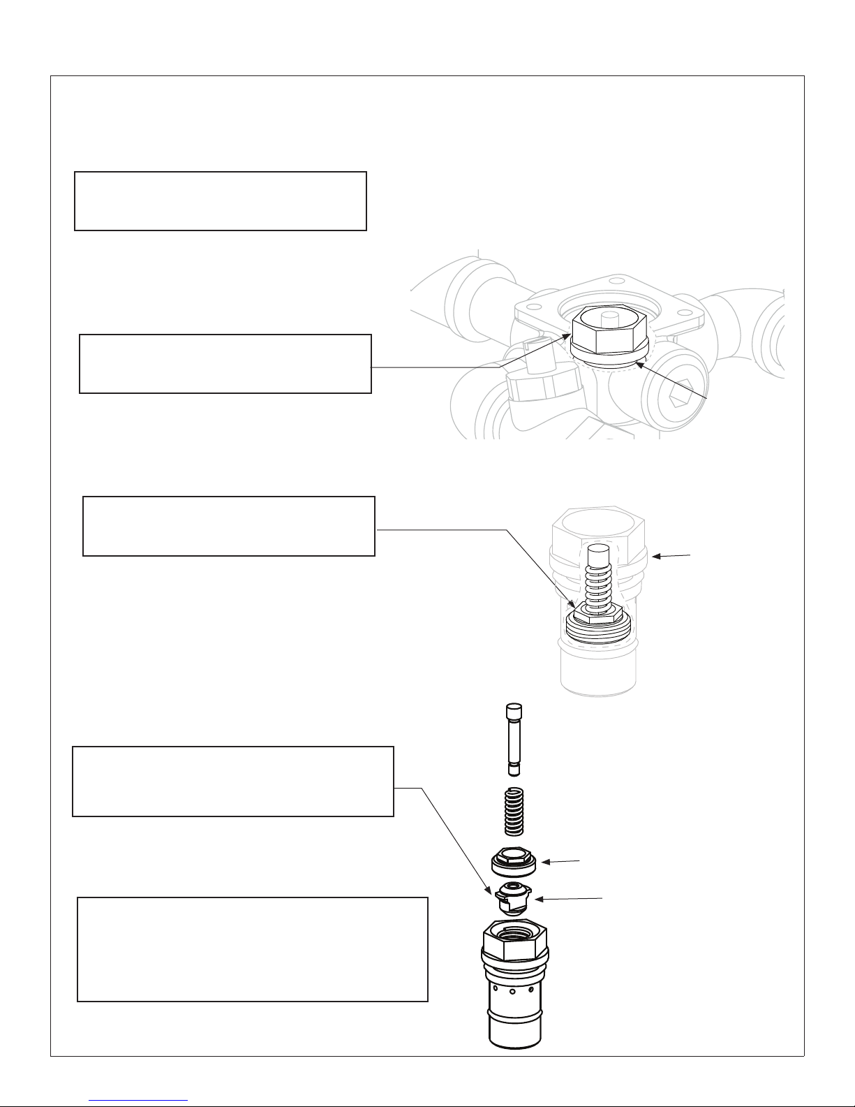
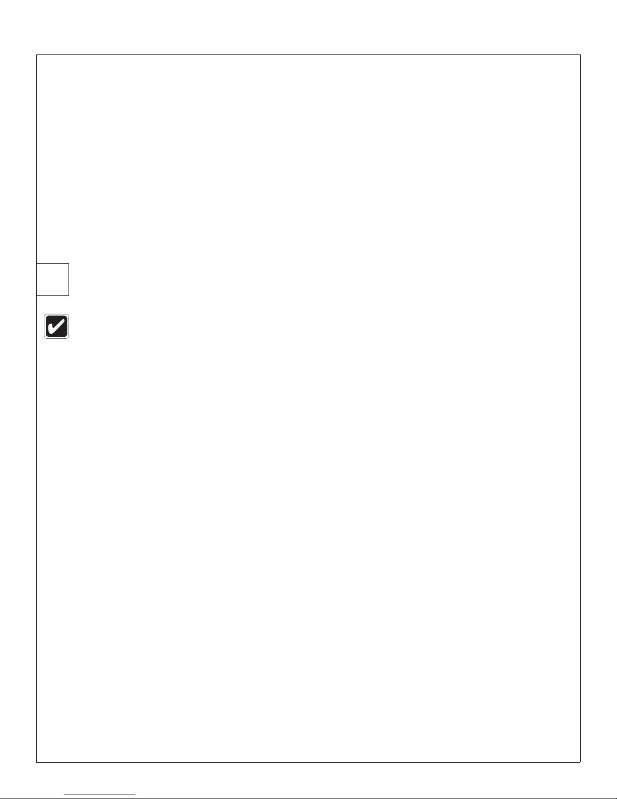
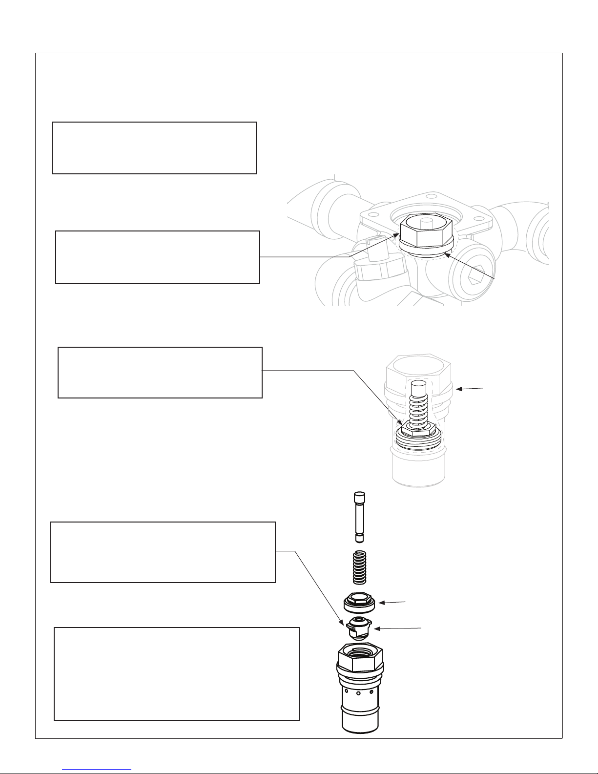
Troubleshooting: Piston Disassembly and Cleaning
Remove the Top Cap and Thermostat
Assembly as shown on Page 6. Set the
A
5/8" Push Rod aside.
Using a 15/16" socket wrench, loosen the
piston liner from the valve body and lift
B
out with a needle-nose pliers.
Piston Liner
Using a 1/2 deep socket wrench, loosen
the piston upper seat from the piston liner
C
and lift out parts with a needle-nose pliers.
Dissamble and clean the piston assembly parts
with any cleaner suitable for brass and stainless
D
steel. (if necessary, use a 400-grit sandpaper to
polish and hone the piston and liner.)
Re-assemble the piston assembly. Push the
mechanism up and down several times to make sure
the piston moves smoothly and consistently. If it is not
E
consistent, repeat Procedure D until it moves freely,
or replace. Contact your Bradley representative and
ask for Piston/Liner Kit (part number S65-172).
Piston Liner
Piston Upper Seat
Piston
8 12/7/2017 Bradley • 215-1291 Rev. S; ECN 17-09-009
Page 9
Installation S19-2000, S19-2000EFX
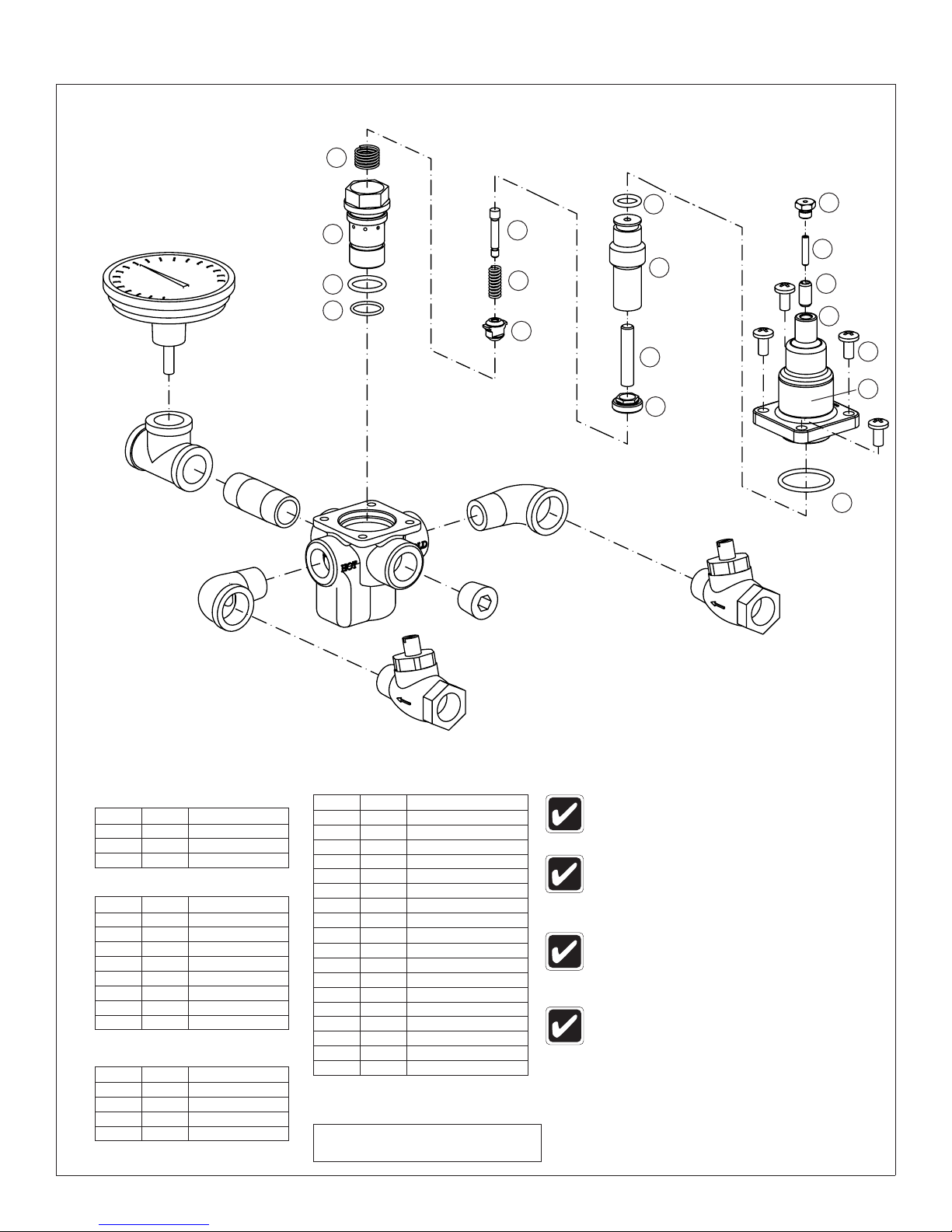
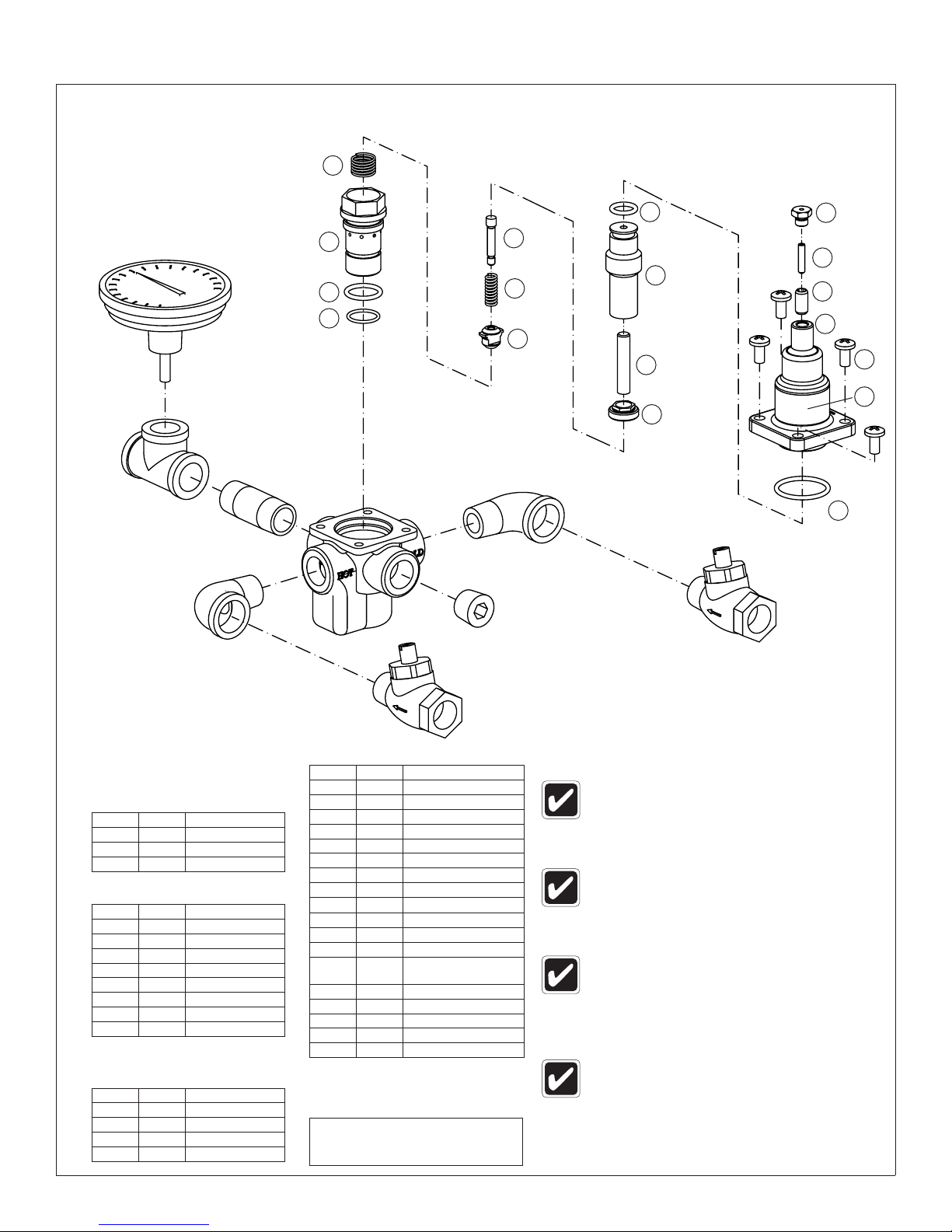
Parts Breakdown
5
1/2" Street Ell
Thermometer
1/2" Brass
Tee
1/2" x 2"
Brass Nipple
12
4
3
2
Valve Body
8
7
6
1/2" Pipe
Plug
11
10
9
1/2" Street Ell
19
17
15
14
18
16
13
Check Stop
Thermostat Kit S65-171
Item Qty. Description
11 1 Thermostat
12 1 O-Ring
13 1 O-Ring
Piston & Liner Kit S65-172
Item Qty. Description
2 1 O-Ring
3 1 O-Ring
4 1 Liner
5 1 Spring
6 1 Piston
7 1 Spring
8 1 Overheat Screw
9 1 Upper Seat
O-Ring Kit S65-170
Item Qty. Description
2 1 O-Ring
3 1 O-Ring
12 1 O-Ring
13 1 O-Ring
NOTICE! Some threaded joints are
Check Stop
Center Section Kit S65-303
Item Qty. Description
2 1 O-Ring
3 1 O-Ring
4 1 Liner
5 1 Spring
6 1 Piston
7 1 Spring
8 1 Overheat Screw
9 1 Upper Seat
10 1 Push Rod
11 1 Thermostat
12 1 O-Ring
13 1 O-Ring
14 1 Control Cap
15 1 Set Screw
16 1 Label
17 1 Set Screw
18 4 1/4 Screw
19 1 Cap
Kit numbers for rough brass finish.
Contact Bradley for other configurations.
As of November 2001, the piston (Item
7) has replaced the seal holder and
seal as a direct replacement.
As of June 2008, the brass control cap
(item 15) has been replaced by a plastic
cap. All internal components are identical.
As of July 2012, the Temperature
Adjustment Control (items 15, 17 and 19)
have been updated and are compatible
with all units using the plastic Control
Cap (June 2008 to present).
Flexible Connection Lines for S19-2000EFX
When used with S19294JB, S19294JBT, order
Part No. 269-653 (3 supplied with unit).
assembled using high strength
thread lock and may require the use
of heat to loosen the connection.
Use caution to not damage o-rings
or other components.
Bradley • 215-1291 Rev. S; ECN 17-09-009 12/7/2017 9
Page 10

S19-2000, S19-2000EFX Installation
AVERTISSEMENT
Tout manquement à respecter les instructions d’installation et d’entretien peut contribuer à une défaillance
du mitigeur entraînant des blessures corporelles graves telles que brûlure, refroidissement et/ou décès suite
à des changements de pression d’eau du circuit et/ou de la température d’arrivée de l’eau.
Utiliser ce mitigeur thermostatique conformément à la norme ASSE 1071. Le fonctionnement des mitigeurs
thermostatiques et appareils d’urgence doit être vérifié chaque semaine suivant ANSI Z3358.1. Ce mitigeur
ne protège pas contre le gel des conduites d’eau.
La température de sortie du mitigeur doit être contrôlée et ajustée lors de l’installation initiale puis tous les
trois mois.
Veiller à bien vidanger et fermer toutes les conduites d’eau avant de commencer l’installation. Tout débris
dans les conduites d’alimentation risque de provoquer un mauvais fonctionnement des soupapes.
Si des vannes d’arrêt sont installées à des fins d’entretien, prendre les mesures nécessaires pour empêcher
les fermetures non autorisées.
AVIS
Le contrôle et le nettoyage régulier des pièces internes et des clapets du mitigeur sont nécessaires pour
assurer un bon fonctionnement et une durabilité maximale du produit. Le contrôle périodique et l’entretien
annuel par un professionnel agréé sont obligatoires. Une eau corrosive et/ou des réglages ou réparations
non autorisés peuvent rendre le mitigeur inopérant quant à l’emploi prévu. La fréquence de nettoyage et de
contrôle dépend des conditions locales d’alimentation en eau.
IMPORTANT
Lire ce manuel d’installation dans son intégralité pour garantir une installation appropriée. Une fois celle-ci
terminée, classer ce manuel auprès du service à la clientèle ou d’entretien. L’installateur est responsable de
respecter la conformité aux codes et ordonnances locaux.
Consulter les codes du bâtiment et de la plomberie en vigueur préalablement à l’installation. Si ces codes
diffèrent des informations figurant dans le manuel, veiller à suivre les codes en vigueur. S’informer auprès
des autorités compétentes s’il existe des exigences locales supplémentaires.
La vanne doit être accessible en position installée pour les essais, les réglages et l’entretien.
Séparer les pièces de l’emballage et veiller à bien avoir toutes les pièces avant de jeter le matériau
d’emballage. Le cas échéant, ne pas commencer l’installation avant d’avoir obtenu les pièces manquantes.
Les garanties du produit se trouvent sous la rubrique « Products » (Produits) sur notre site Web à
bradleycorp.com
10 12/7/2017 Bradley • 215-1291 Rev. S; ECN 17-09-009
Page 11

Installation S19-2000, S19-2000EFX
Fournitures requises pour l’installation :
• Robinet d’arrêt verrouillable sur la sortie en cas d’alimentation d’eau tempérée vers un ou plusieurs appareils
d’urgence
• Robinet d’arrêt verrouillable sur les arrivées/alimentations
• (6) Ancrages muraux et fixations 3/8 po pour armoire montée en surface
• (4) Fixations 1/4 po (et ancrages muraux, si nécessaire) pour armoire encastrée
• Raccords sur toutes les connexions pour faciliter la dépose du robinet
Outils requis pour réglage de température
• Clé Allen 5/64 po
• Tournevis à lame
1
Armoire encastrée :
pas requise, passer à l’étape 2).
En cas de pose du S19-2000EFX dans l’armoire de douche oculaire escamotable
S19-294JB, S19284JBT, voir les instructions de montage fournies avec l’armoire.
1. Ouverture murale pour plomberie brute 292 mm L x
330 mm H (11-1/2 po L x 13 po H).
2. Insérer l’armoire et la fixer au mur avec quatre
fixations 1/4 po adéquatement ancrées (fournies par
l’installateur).
3. Installer deux ancrages et vis à travers le support de
robinet à l’arrière de l’armoire et dans un contrevent
sécuritaire (fourni par l’installateur) ou dans un mur.
Cela soutiendra le robinet.
4. Installer les raccords filetés du robinet et la moitié
du clapet à bille du raccord en utilisant un produit
d’étanchéité pour tuyaux ou du ruban téflon. Installer
l’autre moitié du clapet à bille du raccord sur le tuyau
d’entrée et de sortie.
5. Insérer le robinet dans le support dans l’armoire
(le côté droit entre en premier). Continuer avec la
procédure d’installation du robinet.
Installer l’armoire en option (si l’installation d’une armoire n’est
Armoire montée en surface :
1. Mesurer et marquer les emplacements des trous
de montage de l’armoire selon les dimensions
indiquées à la page suivante. Installer six ancrages
muraux de 3/8 po (fournis par l’installateur).
2. Positionner l’armoire dans le mur et fixer en place
avec six fixations murales de 3/8 po (fournies par
l’installateur).
3. Installer les raccords filetés du robinet et la moitié
du clapet à bille du raccord en utilisant un produit
d’étanchéité pour tuyaux ou du ruban téflon. Puis
installer l’autre moitié du clapet à bille du raccord
sur le tuyau d’entrée et de sortie.
4. Insérer le robinet dans le support dans l’armoire (le
côté droit du robinet entre en premier). Continuer
avec la procédure d’installation du robinet.
6. Positionner la rosace murale tout contre le mur et
colmater en place.
Bradley • 215-1291 Rev. S; ECN 17-09-009 12/7/2017 11
Page 12

S19-2000, S19-2000EFX Installation
Armoire encastrée en option
11¼"
(286)
Porte
(76)
3"
Vue de face
5³⁄₈"
(137)
13"
(330)
5"
(127)
9¾"
(248)
Porte
(279)
Boîtier
11"
Bride
murale
14½"
(368)
Vue de dessous
11"
(279)
2½"
(64)
7½"
(190)
Sortie
½" NPT
Trous de Ø ⁹⁄₃₂" (7)
(4) de chaque côté,
(8) au total
Vue latérale
2"
(51)
2"
(51)
6½"
(165)
2½"
(64)
Arrivées
½" NPT
(mm)
12½"
(318)
2¼"
(57)
Armoire montée en surface en option
9¾"
(248)
Porte
(127)
5"
11"
(279)
Boîtier
11¼"
(286)
Porte
(76)
5½"
(140)
3"
Arrivées
½" NPT
Sortie
½" NPT
6-1/2"
(165)
(51)
2"
2½"
(64)
12½"
(318)
Emplacements de
trous de montage
Trous de Ø ⁵⁄₁₆" (8)
2¼"
(57)
8½"
(216)
(6) au total
12 12/7/2017 Bradley • 215-1291 Rev. S; ECN 17-09-009
11"
(279)
(51)
3¼"
(83)
¾"
2"
(19)
(51)
2"
7"
(178)
5½"
(140)
Page 13

Installation S19-2000, S19-2000EFX
Connecter les conduites d’alimentation et installer le thermostat
2
Eau tempérée
(vers l’appareil)
Mettre LENTEMENT sous pression
pour vérifier l’étanchéité.
Contrôler la température lorsque le débit d’eau atteint
11 à 19 l/min (3 à 5 gal/min) (équivalent à une douche
oculaire ou faciale) et l’ajuster le cas échéant.
Lorsque les clapets de non-retour sont
complètement ouverts (en marche), la tige
dépasse du capuchon d’environ 13 mm (1/2 po).
Ouvrir
Fermer
S19-2000 représenté
Régler la température avec l’eau qui s’écoule
3
Contrôler la température lorsque le débit d’eau atteint 11 à
19 l/min (3 à 5 gal/min) (équivalent à une douche oculaire).
Aucun dispositif d’urgence fourni par ce dispositif a n’a un
débit minimum inférieur à 1,5 GPM (5,7 L/min).
Contrôler la température finale du dispositif et l’ajuster le cas échéant.
La température de consigne standard préréglée à l’usine est de 29 °C
(85 °F) [la plage du robinet est de 18 à 32 °C (65 à 90 °F)]. Insérez
la clé Allen à travers l’orifice du capuchon et dans la vis de calage
pour régler. Consulter les autorités médicales et/ou de sécurité
appropriées pour connaître la température optimale recommandée
pour l’application en question.
Tige de clapet
de non-retour
CHAUD
5/64" Clé Allen
Orifice du
capuchon
C
Capuchon
de tige
FROID
F
4
Fermer l’alimentation d’eau chaude en fermant le clapet ou le robinet d’arrivée d’eau chaude. Pendant que l’alimentation d’eau
chaude est coupée, vérifier que l’eau froide continue de s’écouler. Si l’eau froide s’écoule correctement, rouvrir l’alimentation d’eau
chaude.
Fermer l’alimentation d’eau froide en fermant le clapet ou le robinet d’arrivée d’eau froide. L'arrivée d'eau froide étant coupée,
s'assurer que le débit d'eau chaude a été réduit jusqu'à moins de 0,5 gal/min (1,9 l/min). Si l’eau chaude est coupée, rouvrir
complètement l’arrivée d’eau froide.
Bradley • 215-1291 Rev. S; ECN 17-09-009 12/7/2017 13
Tester unité
Effectuer un essai du système chaque semaine (ouvrir l’arrivée d’eau et vérifier la bonne régulation à la
température de consigne souhaitée).
NE PAS SAUTER CETTE ÉTAPE !!!
Page 14

S19-2000, S19-2000EFX Installation
5
Configuration de recirculation d’eau optionnelle
La recirculation de l’eau dans le circuit assure une régulation constante de la température de l’eau. Purger
les conduites d’alimentation avec soin après avoir terminé l’installation. Fermer tous les appareils et les
condamner provisoirement durant le processus de recirculation.
Clapet de non-retour
(typ.)
Eau froide
FROID
Piège à chaleur
Chute de 28"
(711 mm)
Flux d’eau tempérée
Rupteur thermique
Eau tempérée
recirculée
Pompe de recirculation
Chauffe-eau
CHAUD
Flux de retour
Robinet d’équilibrage (typ.)
Réservoir
1. Couper la pompe de recirculation et ouvrir l’alimentation d’eau au niveau de l’appareil d’urgence (un débit d’eau de 11 à
19 l/min [3 à 5 gal/min] est requis).
2. Laisser l’eau s’écouler à travers le système jusqu’à obtenir une température constante. Si la température souhaitée n’est
pas obtenue, réajuster la température comme indiqué à l’étape 3 à la page précédente.
3. Dès que l’eau atteint la bonne température, activer la pompe de recirculation (vérifier que la température correcte a été
obtenue dans le système avant de poursuivre).
4. Contrôler la température de l’eau au niveau de la pompe de retour. Si la température dépasse le niveau approprié de 1 °C
(2 °F), ajuster le rupteur thermique haut (pour arrêter la pompe). Attendre que la température de retour de l’eau soit de
3 °C (5 °F) en dessous du niveau approprié puis ajuster le rupteur thermique bas (pour remettre la pompe en marche).
5. Ouvrir complètement le robinet d’équilibrage.
6. Couper tous les appareils et vérifier qu’aucune eau ne circule à travers le système (le tuyau d’arrivée d’eau froide doit être
tiède au toucher).
7. Laisser le système fonctionner pendant 30 minutes ou plus sans eau. Si, au bout de trente minutes, la température de
l’eau augmente, elle peut être réajustée en fermant lentement le robinet d’équilibrage jusqu’à atteindre la température qui
convient.
14 12/7/2017 Bradley • 215-1291 Rev. S; ECN 17-09-009
Page 15

Installation S19-2000, S19-2000EFX
Dépannage du robinet mélangeur thermostatique
Avant d’essayer de dépanner le robinet ou de démonter les
composantes, vérifier ce qui suit :
• Les clapets de non-retour sont totalement ouverts
(la tige fendue dépasse d’environ 13 mm (1/2 po) du
capuchon et tous les robinets d’arrêt d’arrivée et de
sortie sont ouverts.
• Les conduites d’arrivée d’eau chaude et froide
sont correctement raccordées et il n’existe ni de
raccordements croisés ni de fuite des clapets de nonretour.
• La sortie du chauffe-eau est d’au moins 11 °C (20 °F)
au-dessus de la température de consigne.
Veiller à bien fermer les robinets d’arrêt adéquats
avant de démonter le robinet et de les rouvrir après
inspection et une fois la réparation terminée.
Capuchon supérieur
et thermostat
Soufflet de
thermostat
Tige-poussoir
de 5/16"
La tige-poussoir doit
s’enfoncer d’une longueur
de 15/16" à 1-3/16" (24 à
30 mm) dans le soufflet
Problème Cause Solution
Fuites externes
dans le système
Pas de circulation
d’eau chaude
(eau froide
seulement)
Débit d’eau limité Le robinet d’arrêt d’arrivée est partiellement
Fluctuation de
température ou
température
incorrecte
Les joints NPT ou les joints toriques sont
endommagés.
Défaillance du thermostat suivie de l’activation
de la vanne d’arrêt de sécurité.
fermé ou la pression d’eau a fortement chuté.
Accumulation de saleté et de débris sur le tamis
ou le siège de clapet, ce qui limite le mouvement
des clapets de non-retour.
Les sections de clapet de non-retour du robinet
ne bougent pas librement.
Lente défaillance du thermostat. Contrôler le thermostat comme décrit plus haut ou le changer.
La conduite d’alimentation d’arrivée vers
le robinet mélangeur est partagée avec
d’autres machines qui ne sont utilisées que
périodiquement, telles que des machines
à laver ou des stations à grand débit. Cela
peut réduire la pression d’arrivée au robinet
mélangeur à moins de 3 PSI. La section de la
conduite d’alimentation peut être insuffisante
pour alimenter à la fois le robinet et les autres
appareils.
La recirculation est déséquilibrée. Examiner la configuration de recirculation à la page 12.
Le piston ne bouge pas librement et doit être
nettoyé.
Remplacer les joints NPT et/ou joints toriques le cas échéant. Pour tout remplacement de
joints toriques, contacter le représentant Bradley et lui demander un Kit de joint torique
(S65-170).
Contrôler le thermostat :
1. Déposer le capuchon supérieur et le thermostat.
2. Enfiler la tige-poussoir de Ø 5/16 po dans le soufflet de thermostat.
3. Marquer la longueur dont la tige s’enfonce dans le soufflet (à température ambiante, sous
une force de 45 N [10 lb], cette longueur doit être d’environ 24 à 30 mm [15/16 à 1-3/16 po]).
4. Si la longueur de tige-poussoir n’est pas dans l’intervalle correct, le thermostat doit être
changé (il n’est pas réparable). Contacter le représentant Bradley et lui demander un Kit de
thermostat (S65-171).
Nettoyer les clapets de non-retour :
démonter les clapets de non-retour, nettoyer le siège et remonter. Ne pas déposer le siège.
Brosser les pièces avec une petite brosse métallique pour éliminer les débris. Utiliser une
pince à épiler pour extraire les débris du siège. Si le clapet de non-retour doit être changé,
contacter le représentant Bradley et lui demander un Kit de clapet de non-retour (S27-102 Laiton brut ou S27-292A - Chrome).
Nettoyer les clapets de non-retour comme décrit ci-dessus.
Augmenter la section de la conduite d’alimentation, reconfigurer l’alimentation ou réguler
l’usage de l’alimentation.
Voir les instructions de démontage et de nettoyage du piston à la page suivante.
Bradley • 215-1291 Rev. S; ECN 17-09-009 12/7/2017 15
Page 16
S19-2000, S19-2000EFX Installation
Dépannage : Démontage du piston et nettoyage
Déposer le capuchon supérieur et le
thermostat comme indiqué à la page 13.
A
Mettre la tige-poussoir de 5/8 po de côté.
À l’aide d’une clé à douille de 15/16 po,
desserrer la chemise de piston du corps de
B
robinet et l’extraire avec une pince à becs
fins.
Chemise de piston
À l’aide d’une clé à douille longue de 1/2
po, desserrer le siège supérieur du piston
de la chemise de piston et extraire les
C
pièces avec une pince à becs fins.
Démonter et nettoyer les pièces du piston avec
tout produit nettoyant convenant pour le laiton
et l’acier inoxydable (le cas échéant, utiliser du
D
papier de verre 400 grains pour polir et rectifier
le piston et la chemise).
Remonter le piston. Pousser le mécanisme vers le
haut et la bas à plusieurs reprises pour vérifier que
le piston bouge régulièrement et sans grippage. Si le
mouvement n’est pas régulier, répéter la procédure
E
D jusqu’à ce qu’il bouge librement ou le changer.
Contacter le représentant Bradley et lui demander un
Kit de piston/chemise (réf. S65-172).
Chemise de piston
Siège supérieur du piston
Piston
16 12/7/2017 Bradley • 215-1291 Rev. S; ECN 17-09-009
Page 17
Installation S19-2000, S19-2000EFX
Liste des pièces
5
Thermomètre
Té en laiton
1/2"
Mamelon en laiton
1/2" x 2"
Coude mâle-femelle
1/2"
Kit Thermostat S65-171
Repère Qté Désignation
11 1 Thermostat
12 1 Joint torique
13 1 Joint torique
Kit Piston et chemise S65-172
Repère Qté Désignation
2 1 Joint torique
3 1 Joint torique
4 1 Chemise
5 1 Ressort
6 1 Piston
7 1 Ressort
8 1 Vis de surchauffe
9 1 Siège supérieur
Kit Joint torique S65-170
Repère Qté Désignation
2 1 Joint torique
3 1 Joint torique
12 1 Joint torique
13 1 Joint torique
4
3
2
Corps de
robinet
Clapet de non-retour
Kit Portion centrale S65-303
Repère Qté Désignation
2 1 Joint torique
3 1 Joint torique
4 1 Chemise
5 1 Ressort
6 1 Piston
7 1 Ressort
8 1 Vis de surchauffe
9 1 Siège supérieur
10 1 Tige-poussoir
11 1 Thermostat
12 1 Joint torique
13 1 Joint torique
14 1 Capuchon de
15 1 Vis calante
16 1 Étiquette
17 1 Vis calante
18 4 Vis 1/4
19 1 Capuchon
commande
Conduites de raccordement
flexibles pour S19-2000EFX
Pour une utilisation avec S19294JB,
S19294JBT, commander réf. 269-653 (3
fournis avec le robinet).
8
7
6
Bouchon de tuyau
1/2"
Coude mâle-femelle
1/2"
12
11
10
9
19
17
15
14
Clapet de
non-retour
AVIS! Certains raccords filetés sont assemblés
avec du frein-filet de haute résistance et
peuvent nécessiter l’utilisation de chaleur
pour les desserrer. Faire preuve de
précaution pour ne pas endommager les
joints toriques et autres pièces.
Numéros de kit pour la finition en
laiton brut. Contacter Bradley pour
toute autre configuration.
À compter de novembre 2001, le
piston (repère 7) remplace directement
le support de joint et le joint.
À compter de juin 2008, le capuchon
de commande en laiton (repère 15) est
remplacé par un capuchon en plastique.
Toutes les pièces internes sont identiques.
À compter d’juillet 2012, la commande
de réglage de température (repères 15,
17 et 19) est reconfigurée et compatible
avec tous les modèles à capuchon de
commande en plastique (juin 2008 à
actuel).
18
16
13
Bradley • 215-1291 Rev. S; ECN 17-09-009 12/7/2017 17
Page 18

S19-2000, S19-2000EFX Installation
ADVERTENCIA
No realizar una instalación correcta ni seguir las instrucciones de mantenimiento podría contribuir a la
falla de la válvula, lo que puede provocar lesiones corporales graves como quemaduras, enfriamiento o la
muerte, dependiendo de los cambios de presión del agua del sistema y los cambios de temperatura del agua
del sistema.
Use esta mezcladora termostática de acuerdo con la norma ASSE 1071. El funcionamiento de las válvulas y
los accesorios de la mezcladora termostática se deben probar semanalmente según la norma ANSI Z3358.1.
Esta válvula no ofrece protección contra el congelamiento de las tuberías.
La temperatura de salida de la válvula se debe revisar y ajustar en la instalación inicial y luego, cada tres
meses.
Asegúrese de purgar todas las tuberías de suministro de agua y que estén completamente cerradas antes
de comenzar la instalación. Los desechos acumulados en las tuberías de suministro pueden provocar
defectos en el funcionamiento de las válvulas.
Si se instalan válvulas de retención para fines de mantenimiento, se deben tomar medidas para evitar el
corte no autorizado.
AVISO
Es necesario revisar y limpiar regularmente los componentes internos y los topes de retención de la válvula
para extender al máximo la vida útil de esta y el funcionamiento adecuado del producto. Se requiere que
un contratista certificado realice las inspecciones periódicas y el mantenimiento anual. Las condiciones
corrosivas del agua y los ajustes o reparaciones no autorizados podrían dejar a la válvula inutilizada
para el servicio que debe proporcionar. La frecuencia de la limpieza y las inspecciones dependen de las
condiciones locales del agua.
IMPORTANTE
Lea en su totalidad este manual de instalación para garantizar una instalación adecuada. Al completar la
instalación, entregue este manual al propietario o al Departamento de Mantenimiento. Es responsabilidad del
instalador cumplir a cabalidad los códigos y las ordenanzas locales.
Consulte los códigos locales de edificación y plomería antes de la instalación. Si estos códigos difieren de
la información de este manual, siga los códigos locales. Pregunte los requisitos locales adicionales a las
autoridades gubernamentales.
Deberá ser posible acceder a las válvulas para realizar pruebas, ajustes y mantenimiento en la posición
instalada.
Saque las piezas del embalaje y asegúrese de haberlas sacado todas antes de desecharlo. Si falta alguna
pieza, no comience la instalación hasta obtenerla.
Las garantías del producto se pueden encontrar en la sección “Products” (Productos) del sitio Web,
bradleycorp.com.
18 12/7/2017 Bradley • 215-1291 Rev. S; ECN 17-09-009
Page 19
Installation S19-2000, S19-2000EFX
Materiales recomendados para la instalación
• Cierre bloqueable en la salida si se suministra agua temperada a uno o más accesorios de emergencia.
• Cierre bloqueable de las entradas o de los suministros.
• (6) anclajes y sujetadores de pared de 1/4 pulg. para el gabinete montado en la superficie.
• (4) sujetadores de 1/4 pulg. (y anclajes de pared, si fuera necesario) para el gabinete empotrado.
• Uniones en todas las conexiones para facilitar el retiro de la válvula.
Herramientas necesarias para el ajuste de temperatura
• Llave Allen de 5/64 pulg.
• Destornillador de paleta.
1
Gabinete empotrado:
con el Paso 2)
Si se instala el modelo S19-2000EFX en el gabinete lavaojos desplegable S19294JB, S19294JBT, consulte
las instrucciones de montaje que se suministran con el gabinete.
1. Orificio de colocación en la pared de 292 mm (11-1/2 pulg.) de
ancho x 330 mm (13 pulg.) de alto.
2. Inserte y fije el gabinete con cuatro sujetadores de 1/4 pulg.
(proporcionado por el instalador) anclados apropiadamente a
la pared.
3. Instale los dos anclajes y tornillos a través del soporte de la
válvula en la parte trasera del gabinete en una abrazadera
firme (proporcionada por el instalador) o en la pared. Esto
servirá de apoyo a la válvula.
4. Instale los niples de la válvula y la mitad de la válvula de
bolas de la unión, usando sellador para tubos o cinta de teflón.
Instale la otra mitad de la válvula de bolas de la unión en el
tubo de entrada y salida.
5. Inserte la válvula en el soporte del gabinete (primero el lado
derecho). Continúe con el procedimiento de instalación de la
válvula.
6. Ponga firmemente la brida de pared en la pared y aplique
masilla para fijarla en su lugar.
Instale el gabinete opcional (si no va a instalar el gabinete, siga
Gabinete montado en la superficie:
1. Mida y marque la ubicación de los orificios de
montaje del gabinete en las dimensiones que
se muestran en la siguiente página. Instale seis
anclajes de pared de 3/8 pulg. (proporcionados
por el instalador).
2. Ponga el gabinete en la pared y fíjelo en su
lugar con seis sujetadores de pared de 3/8
pulg. (proporcionados por el instalador).
3. Instale los niples de la válvula y la mitad de la
válvula de bolas de la unión, usando sellador
para tubos o cinta de teflón. Luego, instale la
otra mitad de la válvula de bolas de la unión en
el tubo de entrada y salida.
4. Inserte la válvula en el soporte del gabinete
(primero el lado derecho de la válvula).
Continúe con el procedimiento de instalación
de la válvula.
Bradley • 215-1291 Rev. S; ECN 17-09-009 12/7/2017 19
Page 20
S19-2000, S19-2000EFX Installation
Gabinete empotrado opcional
Vista frontal
9¾"
(248)
5"
(127)
Puerta
(279)
Caja
11"
11¼"
(286)
Puerta
(76)
5³⁄₈"
(137)
3"
13"
(330)
Brida de
pared
14½"
(368)
Vista inferior
11"
(279)
2½"
(64)
7½"
(190)
Salida de
NPT de ½"
⁹⁄₃₂"(7) de diá.
Orificios
(4) a cada lado,
(8) Total
Vista lateral
2"
(51)
2"
(51)
6½"
(165)
(mm)
2½"
(64)
2¼"
(57)
Entradas de
NPT de ½"
12½"
(318)
Gabinete opcional montado en la superficie
9¾"
(248)
Puerta
5"
(127)
11"
(279)
Caja
Entradas de
NPT de ½"
11¼"
(286)
Puerta
(76)
5½"
(140)
3"
Salida de
NPT de 1/2"
6½"
(165)
(51)
2"
2½"
(64)
12½"
(318)
Ubicación de los orificios
de montaje
⁵⁄₁₆" (8) de diá. Orificios
(6) en total
2¼"
(57)
8½"
(216)
20 12/7/2017 Bradley • 215-1291 Rev. S; ECN 17-09-009
11"
(279)
(51)
3¼"
(83)
¾"
2"
(19)
(51)
2"
7"
(178)
5½"
(140)
Page 21
Installation S19-2000, S19-2000EFX
2
Conecte las tuberías de suministro e instale el termómetro
Tuerca del
vástago
Agua temperada
(para el accesorio)
FRÍA
Revise si hay filtraciones, presurizando
la unidad LENTAMENTE.
Revise la temperatura cuando se alcance un caudal de
agua de 11 a 19 LPM (3 a 5 gpm) (lo equivalente a un
lavado ocular o facial) y ajuste de ser necesario.
Cuando los topes de retención se encuentran en
la posición de abertura completa (funcionamiento),
el vástago se extenderá aproximadamente 13 mm
(1/2 pulg.) desde la tuerca.
Abrir
Cerrar
Se muestra el modelo
S19-2000
Vástago de tope
de retención
Orificio en la tapa
CALIENTE
3
4
Cierre la válvula de entrada de agua caliente o la válvula de retención de suministro para cortar el suministro de agua caliente.
Con el suministro de agua caliente cerrado, verifique que siga fluyendo agua fría. Si el agua fría fluye correctamente, vuelva a abrir
el suministro de agua caliente.
Ajuste la temperatura con el agua corriendo
Revise la temperatura cuando se alcance
aproximadamente un caudal de agua de 11 a 19 LPM
(3 a 5 gpm) (lo equivalente a un lavado ocular).
Ningún accesorio de emergencia que proporcione este
dispositivo tiene un caudal mínimo inferior a 5,7 L/min.
Se debe revisar la temperatura final de este dispositivo y ajustarla,
según sea necesario. La configuración estándar de la temperatura
predeterminada de fábrica es de 29 °C (85 °F) (el rango de
la válvula es de 18 °C a 32 °C [65 °F a 90 °F]). Para ajustar,
inserte la llave Allen a través del orificio en la tapa, en el tornillo
de ajuste. Consulte a las autoridades médicas o de seguridad
correspondientes sobre la temperatura óptima recomendada para
la aplicación en particular.
Unidad de prueba
¡NO SE SALTE ESTE PASO!
5/64" Llave Allen
C
F
Cierre la válvula de entrada de agua fría o la válvula de retención de suministro para cortar el suministro de agua fría. Con el
suministro de agua fría cerrado, verifique que se haya detenido el flujo de agua caliente a menos de 1,9 LPM (0,5 gpm). Si se
detiene el agua caliente, vuelva a abrir completamente el suministro de agua fría.
Pruebe el sistema semanalmente (abra el suministro de agua y verifique que el control de la temperatura
establecida que se desea sea constante).
Bradley • 215-1291 Rev. S; ECN 17-09-009 12/7/2017 21
Page 22

S19-2000, S19-2000EFX Installation
5
Instalación de recirculación opcional de agua
La recirculación del agua en el sistema proporciona regulación constante de la temperatura del agua. Purgue
las tuberías de suministro completamente antes de terminar la instalación. Cierre todos los accesorios y
etiquételos como no disponibles para usarse durante el proceso de recirculación.
Válvula de
retención (Típ.)
Flujo de agua temperada
Interruptor de temperatura
Agua fría
FRÍA
Bajada de
trampa de
calor de 28"
(711 mm)
Agua
temperada
recirculada
Bomba de recirculación
Calentador
de agua
Tanque de
almacenamiento
CALIENTE
Flujo de retorno
Válvula de equilibrio (Típ.)
1. Apague la bomba de recirculación y abra el suministro de agua en los accesorios de emergencia (se requiere un caudal de
agua de 11 a 19 LPM [3 – 5 GPM]).
2. Deje que el agua corra a través del sistema hasta que alcance una temperatura constante. Si no obtiene la temperatura
necesaria, consulte el paso n.° 3 en la página anterior para volver a ajustar la temperatura.
3. Tan pronto como el agua alcance la temperatura apropiada, encienda la bomba de recirculación (antes de proceder,
asegúrese de que se haya alcanzado la temperatura adecuada en el sistema).
4. Revise la temperatura del agua en la bomba de retorno. Si la temperatura excede el nivel apropiado en 1 °C (2 °F), ajuste
el interruptor del límite superior de temperatura (esto apagará la bomba). Espere hasta que la temperatura del agua de
retorno esté a 3 °C (5 °F) por debajo del nivel apropiado y ajuste el interruptor del límite inferior (esto volverá a encender la
bomba).
5. Abra completamente la válvula de equilibrio.
6. Desconecte todos los accesorios y asegúrese de que no fluya agua por el sistema (el tubo de entrada de agua fría debe
sentirse tibio al tacto).
7. Deje que el sistema funcione sin agua durante 30 minutos o más. Si, después de treinta minutos, aumenta la temperatura
del agua, puede volver a ajustar la temperatura cerrando lentamente la válvula de equilibrio hasta que se alcance la
temperatura adecuada.
22 12/7/2017 Bradley • 215-1291 Rev. S; ECN 17-09-009
Page 23
Installation S19-2000, S19-2000EFX
Solución de problemas de la válvula mezcladora termostática
Antes de intentar solucionar problemas de la válvula o desensamblar
los componentes, revise lo siguiente:
• Que las válvulas de cierre o retención estén
completamente abiertas (el vástago ranurado se extienda
aproximadamente 13 mm (1/2 pulg.) a partir de la tuerca
del vástago) y que estén abiertas todas las válvulas de
retención de entrada y salida
• Que los tubos de entrada de agua caliente y fría estén
conectados correctamente y que no existan conexiones
cruzadas ni válvulas de cierre o retención con filtraciones.
• La salida del calentador de agua esté al menos a 11 °C
(20 °F) por sobre la temperatura establecida.
Asegúrese de cerrar las válvulas de retención
correspondientes antes de desensamblar la válvula,
y vuelva a abrir las válvulas después de completar la
inspección y la reparación.
Tapa superior
y termostato
Fuelle del
termostato
Varilla de empuje
de 5/16"
La longitud de la varilla de
empuje se debiera extender
de 15/16" a 1-3/16" (24 a
30 mm) dentro del fuelle
Problema Causa Solución
Filtraciones externas
en el sistema
No fluye agua
caliente (fluye
solamente agua fría)
Flujo limitado de
agua
Fluctuación de
la temperatura
o temperatura
incorrecta
Es posible que se hayan dañado las juntas NPT o las juntas
tóricas.
Falló el termostato y, en consecuencia, se activó la retención
de seguridad.
Es posible que la entrada de la válvula de retención esté
parcialmente cerrada o haya disminuido significativamente la
presión de agua.
Se acumuló suciedad y desechos en la rejilla o asiento de
retención, limitando el movimiento de cierre y retenciones.
Las secciones de cierre y retención de la válvula no se
mueven libremente.
El termostato lentamente comienza a fallar. Revise el termostato como se describe anteriormente o reemplácelo.
La tubería de suministro de entrada hacia la válvula
mezcladora se comparte con otras piezas del equipo que
se usan solamente en forma periódica, tales como aparatos
de lavandería o estaciones de flujo. Esto puede reducir la
presión de entrada hacia la válvula mezcladora a menos de
3 PSI. Es posible que el tamaño de la tubería de suministro
no sea lo suficientemente grande para dar suministro a la
válvula y a los otros aparatos.
La recirculación no está equilibrada. Revise la instalación de la recirculación en la página 19.
El pistón no se mueve libremente y se debe limpiar. Consulte la página siguiente para ver las instrucciones de desensamble y
Remplace las juntas NPT o las juntas tóricas, donde sea necesario. Para el
reemplazo de las juntas tóricas, comuníquese con el representante local de
Bradley y consulte por el kit (S65-170) de sellos de juntas tóricas.
Inspección del termostato:
1. Retire el termostato y la tapa superior.
2. Inserte una varilla de empuje de 5/16 pulg. de diá. en el fuelle del termostato.
3. Marque la distancia en que la varilla de empuje se extiende dentro del fuelle
(a temperatura ambiente, con 45 N [10 lb] de fuerza, la distancia debiera ser
aproximadamente de 24 a 30 mm [15/16 pulg. a 1-3/16 pulg.]).
4. Si la longitud de la varilla de empuje no está en el rango apropiado, se
debe reemplazar el termostato (no se puede reparar). Comuníquese con el
representante local de Bradley y consulte por el Kit (S65-171) del termostato.
Limpie las válvulas de cierre y retención:
Retire el cierre y las retenciones, limpie el asiento y vuelva a ensamblar la
válvula. No retire el asiento. Los componentes se pueden cepillar con un cepillo
de alambre de tamaño pequeño para eliminar los desechos. Un par de pinzas
funciona bien para sacar los desechos del asiento. Si es necesario reemplazar
el cierre y las retenciones, comuníquese con el representante local de Bradley y
consulte por el kit (S27-102: Bronce áspero o S27-292A: Cromo) de retención/
cierre.
Limpie las válvulas de cierre y retención como se describe anteriormente.
Aumente el tamaño de la tubería de suministro, vuelva a configurar la tubería de
suministro o regule el uso del suministro.
limpieza.
Bradley • 215-1291 Rev. S; ECN 17-09-009 12/7/2017 23
Page 24
S19-2000, S19-2000EFX Installation
Solución de problemas: Desensamble y limpieza del pistón
Retire la tapa superior y el conjunto del
termostato según se muestra en la Página
A
20. Ponga la varilla de empuje de 5/8 pulg.
a un costado.
Con una llave de cubo de 15/16 pulg.,
afloje el revestimiento del pistón del
B
cuerpo de la válvula y saque las piezas
con un alicate de punta de aguja.
Revestimiento
del pistón
Con una llave de cubo de 1/2 pulg.,
afloje el asiento superior del pistón del
C
revestimiento del pistón y saque las
piezas con un alicate de punta de aguja.
Desmonte y limpie las piezas del conjunto del
pistón con cualquier limpiador adecuado para
la limpieza de bronce y acero inoxidable (de ser
D
necesario, use una lija de grano 400 para pulir y
afinar tanto el pistón como el revestimiento).
Vuelva a ensamblar el conjunto del pistón. Empuje
el mecanismo hacia arriba y hacia abajo varias
veces para asegurarse de que el pistón se mueva
suave y constantemente. Si es constante, repita el
Procedimiento D hasta que se mueva libremente
E
o cámbielo. Comuníquese con el representante
local de Bradley y consulte por el Kit del pistón y
revestimientos (número de pieza S65-172).
Asiento superior del pistón
Pistón
Revestimiento
del pistón
24 12/7/2017 Bradley • 215-1291 Rev. S; ECN 17-09-009
Page 25

Installation S19-2000, S19-2000EFX
Desglose de piezas
5
Termómetro
T de bronce
de 1/2"
Niple de bronce
de 1/2" x 2"
Codo de rosca macho y
hembra de 1/2"
Kit S65-171 del termostato
Artículo Cantidad Descripción
11 1 Termostato
12 1 Junta tórica
13 1 Junta tórica
Kit S65-172 del pistón y revestimientos
Artículo Cantidad Descripción
2 1 Junta tórica
3 1 Junta tórica
4 1 Revestimiento
5 1 Resorte
6 1 Pistón
7 1 Resorte
8 1 Tornillo de sobre-
9 1 Asiento superior
Kit S65-170 de juntas tóricas
Artículo Cantidad Descripción
2 1 Junta tórica
3 1 Junta tórica
12 1 Junta tórica
13 1 Junta tórica
calentamiento
4
3
2
Cuerpo de la
válvula
Tope de
retención
Kit S65-303 de la sección central
Artículo Cantidad Descripción
2 1 Junta tórica
3 1 Junta tórica
4 1 Revestimiento
5 1 Resorte
6 1 Pistón
7 1 Resorte
8 1 Tornillo de sobre-
9 1 Asiento superior
10 1 Varilla de empuje
11 1 Termostato
12 1 Junta tórica
13 1 Junta tórica
14 1 Tapa de control
15 1 Tornillo de ajuste
16 1 Etiqueta
17 1 Tornillo de ajuste
18 4 Tornillo de 1/4
19 1 Tapa
Tuberías flexibles de conexión para el
modelo S19-2000EFX
Cuando se usa con el modelo S19294JB,
S19294JBT, el n.° de solicitud de pieza es
269-653 (se suministran 3 con la unidad).
calentamiento
12
8
7
6
Tapón de tubo
de 1/2"
Codo de rosca macho
y hembra de 1/2"
11
10
9
AVISO! Algunas juntas roscadas se montan
con cierre de roscas de alta resistencia
y se puede necesitar el uso de calor
para soltar la conexión. Tenga cuidado
de no dañar las juntas tóricas y otros
componentes.
Números de kit para acabado de bronce
áspero. Comuníquese con Bradley para
consultar por otras configuraciones.
A partir de noviembre de 2001, el pistón
(artículo 7) reemplaza al soporte del
sello y al sello como un repuesto directo.
A partir de junio de 2008, la tapa de
control de bronce (artículo 15) se
reemplazó por una tapa de plástico. Todos
los componentes internos son idénticos.
A partir de julio de 2012, se ha
actualizado el control de ajuste de
temperatura (artículos 15, 17 y 19) y con
compatibles con todas las unidades que
usen la tapa de control plástica (junio de
2008 hasta la actualidad).
19
15
14
Tope de
retención
17
18
16
13
Bradley • 215-1291 Rev. S; ECN 17-09-009 12/7/2017 25
 Loading...