

Page 1
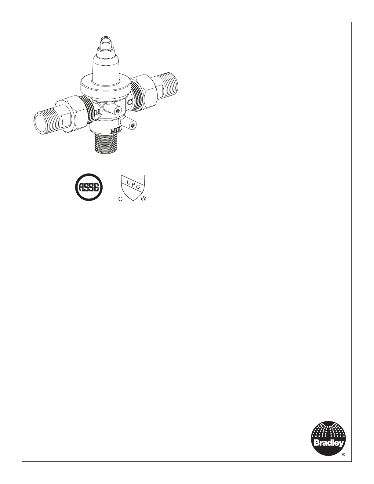
ASSE 1070 & cUPC certified
®
Inlet Connections: 1/2" NPT
Outlet Connection: 1/2" NPT
Temperature Range: 95 – 125°F
Maximum Pressure: 125 PSIG
Inlet Temperature, Hot: 120 – 180°F
Inlet Temperature, Cold: 33 – 80°F
Minimum Temperature Differential (from valve set point): 10°F
Installation
S59-4007
Navigator® Thermostatic Mixing
Valve for Sinks/Faucets
Pre-Installation Information ........................2
Supplies and Tools Required.......................2
Installation .....................................3
Troubleshooting .................................4
Parts List ......................................4
215-1852 Rev. C; ECN 18-09-011
© 2018 Bradley
Page 1 of 4 2/1/2018
Menomonee Falls, WI 53052 USA
P.O. Box 309
800 BRADLEY (800 272 3539)
+1 262 251 6000
bradleycorp.com
Page 2

S59-4007 Installation
WARNING
Failure to comply with proper installation and maintenance instructions could contribute to the valve failure
resulting in severe bodily injury including scalding, chilling, and/or death depending upon system water
pressure changes and/or supply water temperature changes.
Use this Thermostatic Mixing Valve in accordance with ASSE standard 1070. This valve does not provide
protection from pipe freezing.
Output temperature of the valve must be checked and adjusted at initial installation and on a quarterly basis.
Make sure that all water supply lines have been flushed and then completely turned off before beginning
installation. Debris in supply lines can cause valves to malfunction.
NOTICE
Regular checking and cleaning of the valve’s internal components is necessary for maximum life and proper
product function. Periodic inspection and yearly maintenance by a licensed contractor is required. Corrosive
water conditions, and/or unauthorized adjustments or repairs could render the valve ineffective for its
intended service. Frequency of cleaning and inspection depends upon local water conditions.
IMPORTANT
Read this entire installation manual to ensure proper installation. When finished with the installation, file
this manual with the owner or maintenance department. Compliance and conformity to local codes and
ordinances is the responsibility of the installer.
Consult local building and plumbing codes prior to installation. Should these codes differ from the
information in the Manual, follow the local codes. Inquire with governing authorities for additional local
requirements.
Separate parts from packaging and make sure all parts are accounted for before discarding packaging
material. If any parts are missing, do not begin installation until you obtain the missing parts.
Product warranties may be found under “Products” on our web site at bradleycorp.com.
Supplies Required
• Shut-off on the outlet if tempered water is
supplied to a remote location
• Shut-off on the inlets/supplies
• (2) #10 fasteners (and wall anchors, if
necessary) for wall bracket
Tools Required
• Adjustable Wrench
• Needle-Nose Pliers
• Phillips-Head Screwdriver
2 2/1/2018 Bradley • 215-1852 Rev. C; ECN 18-09-011
Page 3

Installation S59-4007
Assemble the Valve
1
Install check valves into valve assembly
A
as shown in the Parts List.
Observe direction of arrow on check
valve when assembling.
Slide tailpiece nuts over tailpieces.
B
Connect Supply Lines
2
Thread hot and cold supplies to
tailpieces. Thread mix outlet line to the
A
valve body outlet.
NOTICE! If tailpieces need to be soldered to
the hot and cold supplies, detach the
tailpieces from valve assembly or the
valve may be damaged.
Pressurize the thermostatic mixing
B
valve and check for pipe leaks.
Insert fiber washers between tailpieces
and hot and cold inlets on the valve
C
assembly. Tighten tailpiece nuts onto
valve body.
Hot
Mix
(to Faucet)
Cold
Adjust Temperature with Water Running
3
This valve is NOT factory preset. Upon installation, the temperature of this valve must be checked and adjusted
to ensure delivery of a safe water temperature. Water in excess of 110°F (43°C) may cause scalding.
Loosen cap screw about
1/4" (4-6 turns) and lift up
A
cover (do not remove)
H
Using cover, turn cartridge gently
until desired water temperature is
reached. Do not turn past stops as
B
this may damage unit. Push cover
down and tighten screw.
Test Unit
4
Shut the hot water inlet off by closing hot water inlet valve. While the hot water supply is turned off, check to make
sure the cold water flow is reduced. If the cold water is reduced properly, reopen the hot water supply.
Shut the cold water inlet off by closing the cold water inlet valve. While the cold water supply is off, check to make
sure that the hot water flow has shut down.
DO NOT SKIP THIS STEP!!!
C
Bradley • 215-1852 Rev. C; ECN 18-09-011 2/1/2018 3
Page 4

S59-4007 Installation
Thermostatic Mixing Valve Troubleshooting
Before attempting to troubleshoot the valve or disassemble the components, check for the following conditions:
• If stop valves are used, make sure that they are fully open.
• Make sure that the hot and cold inlet pipes are connected properly, and that there are no crossconnections or leaking stop valves.
• Check the hot water heater output to make sure that it is at least 10° F above the set temperature.
Be sure to close the appropriate shut-off valves prior to disassembly of the valve and reopen the valves after
inspection and repair is complete.
Problem Cause Solution
External leaks. Damaged cartridge or O-rings. Replace cartridge with part number 269-1927
Improper water temperature
or temperature fluctuation.
Hot water supply is not 10° above desired set
point.
Valve temperature is not properly set. Adjust the temperature as shown on page 3 step 2.
Increase hot water supply temperature
Limited water flow. Dirt and debris have built up in the valve or
strainer.
Parts List
Item Part No. Description Qty
1 118-333 Valve Body 1
5
4
3
2 269-1927 Thermostatic Cartridge 1
3 107-646 Hex Cap 1
4 107-582A Cover, Lead Free Valve 1
5 160-463 Screw, M4X8 PN 1
6 198-012 Check Valve, 16mm 2
7 124-001AF Rubber Washer 2
8 129-007 Tailpiece, Unplated 2
9 110-005 Nut, 1-1/16-14 Hex 2
10 S45-2976 Mounting Bracket Kit (Optional) 1
1. Check to make sure both hot and cold supplies are
connected to the Navigator mixing valve and that they
have water flow.
2. Remove cover and U-clip. Remove the cartridge
and clean the strainer. It is not required to grease
cartridge, however if desired, use silicone grease only.
Do not use grease on check valves.
10
4 2/1/2018 Bradley • 215-1852 Rev. C; ECN 18-09-011
2
6
1
7
8
9
 Loading...