

Bradley LavCare LC500 L/F, LavCare LC500 L/W Installation And Maintenance Instructions Manual
Page 1
Bradleys
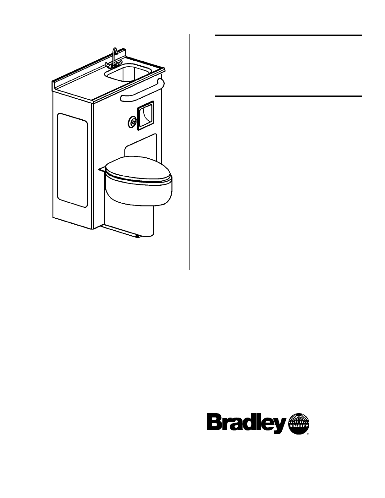
LavCare 500
Series Patient
Care Module
Models LC500 L/F
and L/W)
Installation and
Maintenance
Instructions
215-857 Rev. B; EN 97-1016
Page 1 of 11
Table of Contents
Pre-Installation Information . . . . . . . . . . . . . . .2
LC500 Components and Dimensions . . . . . . . .3
LC500 L/F Rough-Ins . . . . . . . . . . . . . . . . . . .4
LC500 L/W Rough-Ins . . . . . . . . . . . . . . . . . . .5
Installation Instructions . . . . . . . . . . . . . . . .6-10
Cleaning and Maintenance . . . . . . . . . . . . . . .11
P.O. Box 309, Menomonee Falls, WI 53052-0309
Phone (262) 251-6000 Fax (262) 251-5817
http://www.bradleycorp.com
Page 2

Pre-Installation Information
Overview
The Bradley LavCare module is a patient water closet and lavatory station in one unit. The unit
has three access panels for ease of installation and maintenance. The LC500 countertop is made
from cultured marble and the water closet is stainless steel.
Supplies required for installation:
(6) wall anchors and bolts to secure cabinet to wall at 3/4 mounting holes
Steel angles and hardware for anchoring the water closet (if concrete is lightweight or
less than 4 thick)
4 floor/wall closet waste connection fittings
Shims (for water closet or cabinet installation, if necessary)
Supply piping to water closet and faucet or foot valve
Waste outlet piping to water closet
P-trap and drain piping
Silicone caulk
Bradley LavCare 500 Series Patient Care Module
Model LC500 L/F and L/W Installation Instructions
2 Bradley Corporation 215-857 Rev. B; EN 97-1016
Bradley LavCare 500 Module Warranty Information
Bradley Corporation warrants to commercial and institutional purchasers only each unit free from defects in material and workmanship under normal use and service upon the following terms and conditions:
1. This warranty is limited to replacing or repairing, at our option, transportation charges prepaid by the purchaser, any Bradley unit or
part thereof which our inspection shall show to have been defective within the limitations of this warranty.
2. The period during which LC500 components are warranted is one (1) year, measured from the date of our invoice.
3. This warranty does not cover installation or any other labor charges and does not apply to any units which have been damaged by
accident, abuse, improper installation or improper maintenance.
4. The replacement or repair of defective units as stated in this warranty shall constitute the sole remedy of the purchaser and the sole
liability of Bradley Corporation under this warranty. Bradley Corporation shall not otherwise be liable under any indirect damages
caused by defects in the repair or replacement thereof.
5. This warranty extends only to commercial and institutional purchaser and does not extend to any others, including consumer customers of
commercial institutional purchasers.
6. This warranty is in lieu of all other warranties, expressed or implied, including any implied warranty of merchantability or fitness for
a particular purpose or otherwise.
IMPORTANT
Read this entire instruction sheet to ensure proper installation.
Flush all the water supply lines before making connections.
File these instructions with the owner or maintenance department.
Page 3
Bradley LavCare 500 Series Patient Care Module
Installation Instructions Model LC500 L/F and L/W
3Bradley Corporation 215-857 Rev. B; EN 97-1016
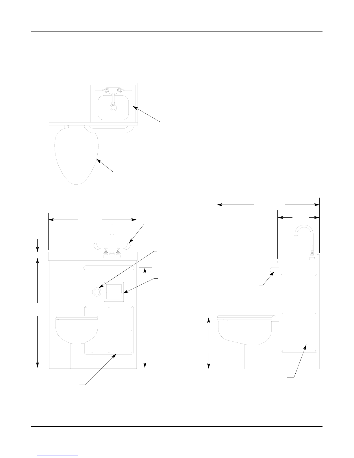
LC500 Components and Module Dimensions
4 WRISTBLADE
CENTERSET FAUCET
FLUSH
ACTUATOR
RECESSED
TOILET
TISSUE
HOLDER
15 (381) X 15 (381)
ACCESS PANEL
2
(51)
(MM)
36-1/8
(918)
29 (737)
32-7/8
(835)
CULTURED
MARBLE
COUNTERTOP
WATER CLOSET
WITH HINGED SEAT
GRAB BAR
10 (254) X 24 (610)
ACCESS PANEL
17
(432)
13-7/8
(352)
33-1/4 (845)
Page 4
Bradley LavCare 500 Series Patient Care Module
Model LC500 L/F and L/W Installation Instructions
4 Bradley Corporation 215-857 Rev. B; EN 97-1016
Installation Instructions
Step 1: Rough-in supply, drain and waste piping
NOTE: Use the submittal drawing when roughing in the LC500.
IMPORTANT: Flush the supply lines before making connections. Debris in supply
lines can cause the valves to malfunction.
1. Rough in supply, drain and waste piping to the LC500 module as required for your installation.
NOTE: For modules with foot pedal option or for retrofit installations, refer to special rough-ins
included with your LC500 module.
Figure 1a
LC500 L/F (floor waste)
Installation Instructions continue . . .
1/2 NPT HOT WATER
INLET TO LAVATORY
1/2 NPT COLD WATER
INLET TO LAVATORY
1-1/2 NPT
LAVATORY DRAIN
1 NPT WATER
CLOSET INLET
(6) WALL ANCHORS
AND BOLTS (SUPPLIED
BY INSTALLER
(MM)
Page 5

Bradley LavCare 500 Series Patient Care Module
Installation Instructions Model LC500 L/F and L/W
5Bradley Corporation 215-857 Rev. B; EN 97-1016
Installation Instructions continue . . .
Figure 1b
LC500 L/W (wall waste)
1/2 NPT HOT WATER
INLET TO LAVATORY
1/2 NPT COLD WATER
INLET TO LAVATORY
1-1/2 NPT
LAVATORY DRAIN
1 NPT WATER
CLOSET INLET
5-1/2 FLANGED
WASTE OUTLET
(6) WALL ANCHORS
AND BOLTS (SUPPLIED
BY INSTALLER
(MM)
NOTE: For modules with foot pedal option or for retrofit installations,
refer to special rough-ins included with your LC500 module.
Page 6

Bradley LavCare 500 Series Patient Care Module
Model LC500 L/F and L/W Installation Instructions
6 Bradley Corporation 215-857 Rev. B; EN 97-1016
Installation Instructions continue . . .
Figure 3
Installation Instructions continued . . .
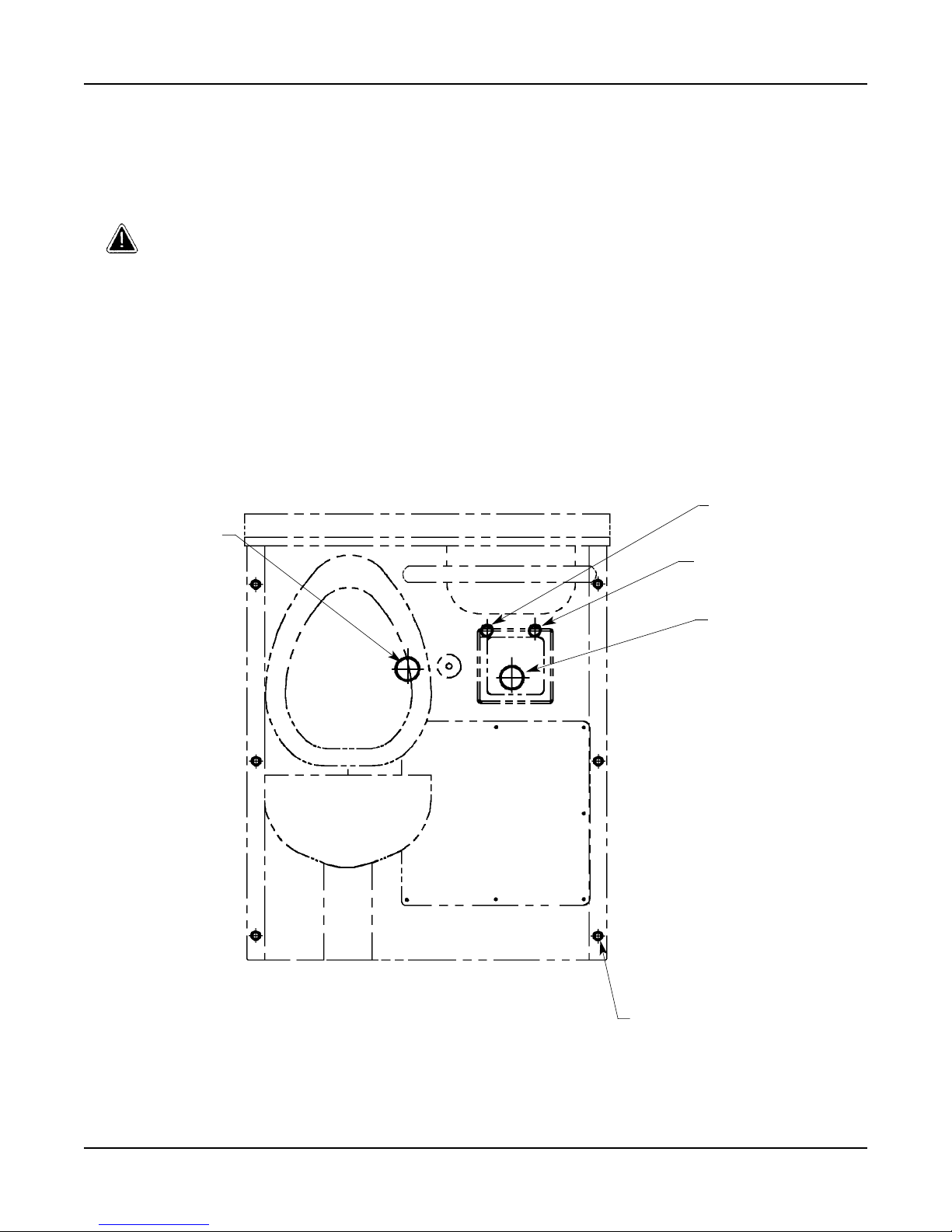
Step 2: Install wall and floor anchors
WARNING:
All mounting hardware provided is
essential in properly anchoring the
fixture. Bradley cannot assume any
responsibility for personal injury or
damage to equipment due to an
improperly installed LC500 module.
1. Remove the #10-24 screws from the three
access panels (one on each side and one on the
front) and lift off the panels (see Figure 2a/2b).
Set the screws and access panels aside.
2. Position the LC500 module in place against
the wall and piping. Mark the locations for the
six wall anchors on the wall and the two water
closet anchors on the floor (see Figure 2a/2b).
3. Set the LC500 module aside and install six
wall anchors (supplied by installer) at the
locations marked in #2 above.
4. Using a 5/8 concrete drill bit, drill two 2-1/8
deep holes into the water closet anchoring
locations (see Figures 2a/2b and 3). Holes
must be clean and free of debris.
5. Drive the two 2-1/8 anchors provided into the
drilled holes for the water closet using the
setting tool (provided) and a hammer. The
anchor should be driven in flush with the floor
(see Figure 3).
NOTE: If the floor concrete is lightweight or less
than 4 thick, Bradley recommends through-bolting
to steel angles under the floor (hardware supplied
by installer) (see Figure 4).
6. Install the 2 threaded studs provided into the
four 2-1/8 anchors installed in #5 above.
Figure 2a
Figure 4
(6) MOUNTING HOLES
FOR SECURING TO WALL
(6) #10-24
SCREWS
ACCESS
PANEL
(2) MOUNTING
HOLES FOR
SECURING TO
FLOOR
5/8 (16) DIAMETER
DRIVE ANCHOR IN
FLUSH WITH FLOOR
2-1/8 (54)
DEEP
(MM)
WATER CLOSET
PEDESTAL BASE
Figure 2b
(6) MOUNTING HOLES
FOR SECURING TO WALL
(6) #10-24
SCREWS
ACCESS
PANEL
(2) MOUNTING
HOLES FOR
SECURING TO
FLOOR
Page 7

Bradley LavCare 500 Series Patient Care Module
Installation Instructions Model LC500 L/F and L/W
7Bradley Corporation 215-857 Rev. B; EN 97-1016
Figure 6
Installation Instructions continued . .
.
Step 3: Install the LC500 cabinet
1. Position the module against the wall and align
the mounting holes in the frame with the wall
anchors. The water closet floor mounting holes
should be placed over the threaded studs
installed in Step 2 on page 6 (see Figure 5a/5b).
2. Secure the cabinet to the back wall using six
bolts (supplied by installer).
3. Bolt the water closet to the threaded studs on
the floor using the security nuts and driver
provided (see Figures 5a/5b and 6).
Figure 5a
Installation Instructions continue . . .
(6) WALL MOUNTING HOLES
(2) WATER CLOSET
FLOOR MOUNTING HOLES
LC500 FRAME
(2) THREADED
STUDS
NUT
DRIVER
SECURITY
NUT
Figure 5b
(6) WALL MOUNTING HOLES
(2) WATER CLOSET
FLOOR MOUNTING HOLES
LC500 FRAME
(2) THREADED
STUDS
Page 8

Installation Instructions continue . . .
Bradley LavCare 500 Series Patient Care Module
Model LC500 L/F and L/W Installation Instructions
8 Bradley Corporation 215-857 Rev. B; EN 97-1016
Figure 7
Step 4: Make water closet supply inlet
and waste connections
NOTE: If the waste outlet goes through the back
wall, a no-hub-type connector may be used (the
connector is available as an option from your
Bradley representative) (see Figure 7).
1. Connect the flush valve water supply piping to
the flush valves 1 NPT inlet (piping supplied
by installer).
2. Connect the water closet waste piping to the
floor waste outlet or wall waste outlet (using a
waste outlet connection fitting supplied by
installer) (see Figure 8a/8b).
FINISHED WALL
LC500
CABINET
NO-HUB
CONNECTOR
Figure 8a
WATER CLOSET
WASTE FLANGE
WASTE
PIPE
GASKET
Figure 8b
GASKET
WASTE
PIPE
WATER CLOSET
WASTE FLANGE
Page 9

9Bradley Corporation 215-857 Rev. B; EN 97-1016
Bradley LavCare 500 Series Patient Care Module
Installation Instructions Model LC500 L/F and L/W
Installation Instructions continued . . .
Step 5: Install the countertop to the
cabinet
1. Apply a bead of silicone caulk (supplied
by installer) around the top edge of the
cabinet and between the countertop and
the wall (see Figure 9).
2. Set the countertop in place on the cabinet.
3. Clean up any excess caulk around the
edge of the countertop.
Step 6a: Install faucet (with wristblade faucet valve) and connect
water supply
NOTE: On LC500 models with the foot valve
faucet, refer to step 6b found on page 10. On
LC500 models with the optional Futura
faucet, use installation instructions specifically
for the Futura faucet when installing the
faucet and making the electrical connections.
NOTE: To make supply connections easier,
remove the access panels first.
1. Place the faucet onto the countertop,
gently inserting the two faucet supply
shanks through the holes provided in the
lavatory bowl (see Figure 10).
2. Install the two washers provided onto
the supply shanks from beneath the
countertop. Secure the washers and the
faucet to the countertop with the two
wingnuts provided (see Figure 10).
3. Connect the hot and cold water supplies
to the faucets 1/2 NPT hot and cold
supply inlets (piping supplied by
installer) (see Figure 10).
4. Install the P-trap (supplied by installer)
to the sinks 1-1/4 O.D. drain pipe
5. Connect the P-trap to the 1-1/4 NPT
drain pipe from the wall (piping supplied
by installer).
Figure 9
Figure 10
COUNTERTOP
SILICONE CAULK
WINGNUT
COUNTERTOP
1/2 NPT
HOT INLET
1/2 NPT
COLD INLET
WASHER
LAVATORY
BOWL
Installation Instructions continue . . .
Page 10

Bradley LavCare 500 Series Patient Care Module
Model LC500 L/F and L/W Installation Instructions
10 Bradley Corporation 215-857 Rev. B; EN 97-1016
Installation Instructions continued . . .
Step 6b: Install faucet (with foot valve)
and connect water supply
NOTE: On LC500 models with the wristblade
faucet valve, refer to step 6a found on page 9.
On LC500 models with the optional Futura
faucet, use installation instructions specifically
for the Futura faucet when installing the
faucet and making the electrical connections.
NOTE: To make supply connections easier,
remove the access panels first.
1. Place the faucet onto the countertop, gently
inserting the two faucet supply shanks
through the holes provided in the lavatory
bowl (see Figure 11).
2. Install the two washers provided onto the
supply shanks from beneath the countertop.
Secure the washers and the faucet to the
countertop with the two wingnuts provided
(see Figure 11).
3. Connect one end of the flexible supply
hose provided to the supply shank (see
Figure 11).
4. Connect the other end of the supply hose
to the foot valve outlet connection (see
Figure 12).
5. Secure the foot valve to the floor using
anchors and bolts (supplied by installer).
6. Connect the hot and cold water supply
(piping supplied by installer) to the 1/2
NPT inlet connectors on the foot valve
(see Figure 12).
Step 7: Complete installation
1. Turn on the water supplies to your
LC500 module and check for leaks.
2. Activate the faucet and flush the valve
several times to purge the air from the
supply lines.
3. Secure the three access panels to the
LC500 with the screws provided.
Figure 11
Figure 12
Installation Instructions continue . . .
GOOSENECK
SPOUT
LAVATORY
BOWL
SUPPLY
SHANK
SUPPLY
HOSE
SUPPLY
HOSE
FOOT
VALVE
FOOT VALVE
OUTLET
CONNECTION
HOT
INLET
COLD
INLET
FOOT VALVE INLET
CONNECTORS
Page 11

11Bradley Corporation 215-857 Rev. B; EN 97-1016
Bradley LavCare 500 Series Patient Care Module
Installation Instructions Model LC500 L/F and L/W
LC500 Module Cleaning and Maintenance
Regular cleaning greatly prolongs the service life of stainless steel and Brad-glazed fixtures and, at the
same time, helps to maintain a pleasing surface appearance. The amount and frequency of cleaning
depends on the service conditions involved. For best results, fixtures should be cleaned as often as
films or deposits become apparent. This will remove built-up deposits which may eventually cause
concentration cells to set on the surface.
CAUTION: USING CLEANERS THAT CONTAIN HARSH CHEMICALS,
ABRASIVES, ACIDS OR DISINFECTANTS, OR CLEANING
WITH STEEL WOOL OR BRUSHES, WILL RESULT IN DAMAGE
TO THE FIXTURES SURFACE. ALWAYS READ THE LABEL
ON ANY CLEANING PRODUCT BEFORE APPLYING TO YOUR
BRAD-GLAZED OR STAINLESS STEEL FIXTURE.
Cleanliness is of utmost importance. Ordinary deposits of dirt and grease can be quickly removed with
soap and water. To properly clean your LC500,
give the Brad-glazed fixture a thorough cleaning with a non-abrasive liquid tub-and-tile
cleaner to remove soil and maintain the glossy finish
You may safely use the following cleaners*:
Formula 409® Spic and Span® Powder
Liquid Comet® Mr. Clean®
Soft Scrub® Windex®
Glass Plus®
DO NOT use the following:
Whitecap® Lysol® Disinfectant Spray
Lestoil® Dow® Disinfectant Bathroom Cleaner
Pinesol® acetone
alcohol steel wool/steel brushes
remove all material and deposits that tend to adhere to the Brad-glazed surface, taking special
note of crevices and corners
remove all material and deposits that tend to adhere to the stainless steel surface with stainless
steel polishing powder (always rub in the direction of the polishing lines)
check for rust spots or streaks on the stainless steel surface and look for the source of the rust
(a steel nail located in some iron or steel not actually a part of the stainless steel fixture may
be the cause)
rinse the Brad-glazed and stainless steel surfaces thoroughly and dry completely after washing.
*NOTE: Use of proprietary cleanser names is intended only to suggest a type of cleanser and
does not constitute endorsement. Omission of any proprietary cleanser name is not
meant to imply its inadequacy.
 Loading...