

Page 1
Installation
Instructions
215-1299 Rev. H; EN 06-909
© 2007 Bradley Corporation
Page 1 of 10 1/29/07
P.O. Box 309, Menomonee Falls, WI 53052-0309
Phone: 1-800-BRADLEY Fax: 262-251-5817
http://www.bradleycorp.com
Table of Contents
Pre-Installation Information . . . . . . . . . . . . . . . .2
Installation Instructions . . . . . . . . . . . . . . . . . . .3
Recess-Mounted Cabinet Installation . . . . . . . . .4
Surface-Mounted Cabinet Installation . . . . . . . .5
Recirculation Instructions . . . . . . . . . . . . . . . . . 6
Maintenance . . . . . . . . . . . . . . . . . . . . . . . . . .7-8
Troubleshooting . . . . . . . . . . . . . . . . . . . . . . . .8-9
Parts Breakdown and Service Kits . . . . . . . . . .10
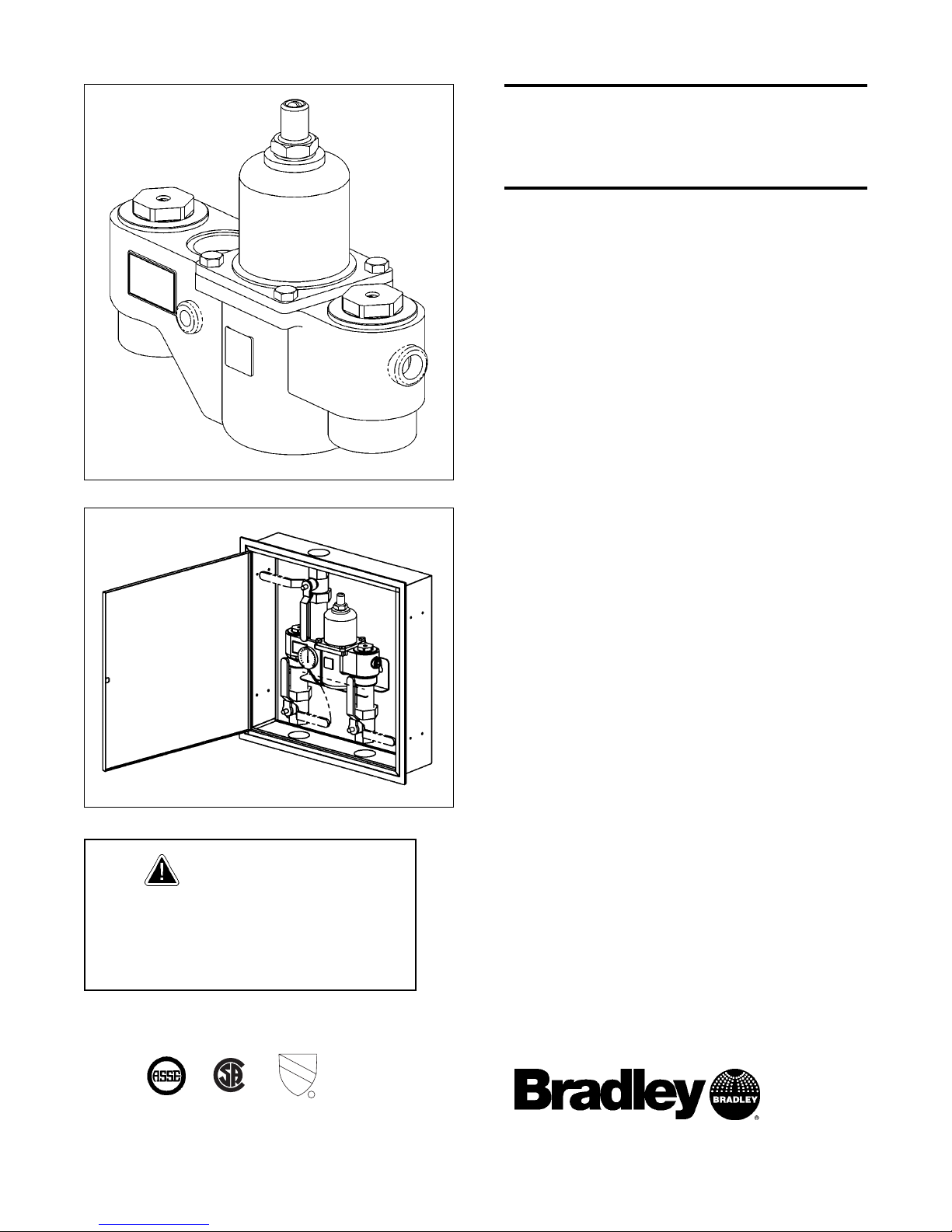
Thermostatic Mixing
Valve (HL 200) with
Optional Cabinet
Model S59-3200 (Valve only)
Model S59-3200RE (with Recess-Mounted
Enamel Cabinet)
Model S59-3200RS (with Recess-Mounted
Stainless Steel Cabinet)
Model S59-3200SE (with Surface-Mounted
Enamel Cabinet)
Model S59-3200SS (with Surface-Mounted
Stainless Steel Cabinet)
Inlet Connections: 2" NPT
Outlet Connections: 2" NPT
Temperature Range: 90–120°F
Maximum Pressure: 125 PSIG
Inlet Temperature, Hot: 120°–200°F
Inlet Temperature, Cold: 33°–80°F
Minimum Temperature Differential
(from valve set point): 20°F
IMPORTANT
Installation and final temperature
adjustment are the responsibility
of the installer.
ASSE 1017, CSA & UPC Certified
U
®
US
C
P
C
C
R
Page 2

Bradley Thermostatic Mixing Valve (HL 200) with Optional Cabinet
Model S59-3200 Series Installation and Maintenance Instructions
2 Bradley Corporation • 215-1299 Rev. H; EN 06-9091/29/07
Bradley Thermostatic Mixing Valve Warranty
Bradley Corporation warrants to commercial and institutional purchasers only each fixture free from defects
in material and workmanship under normal use and service upon the following terms and conditions:
1. We will replace, without charge, any part which proves to be defective within one year from the date of
our invoice at our option, F.O.B. Menomonee Falls, Wisconsin.
2. This warranty does not cover installation or any other labor charge and does not apply to fixtures which
have been damaged by accident, abuse or improper maintenance.
3. The repair or replacement of the defective fixtures as stated in this warranty shall constitute the sole
remedy of the purchaser, and the sole liability of the Bradley Corporation under this warranty. Bradley
Corporation shall not otherwise be liable under any circumstances for incidental, consequential or indirect
charges caused by defects in fixtures or any delay in the repair or replacement thereof.
4. This warranty extends only to commercial and institutional purchases and does not extend to any others,
including consumer, customers of commercial and institutional purchasers.
5. This warranty is in lieu of all other warranties expressed or implied, including any implied warranty of
merchants ability or fitness for a particular purpose, or otherwise.
Pre-Installation Information
Overview
The Model HL 200 Thermostatic Mixing Valve consists of a liquid-filled thermal motor and a
piston control mechanism with positive shut-off of hot when there is a loss of cold water supply
or thermostat failure. The valve body and cap is constructed of bronze with replaceable corrosionresistant components, including a stainless steel piston and liner. The valve comes equipped with
integral check stops that have removable strainers. The valve may be mounted in any position.
The valve controls temperature within ±3° from a low flow to a maximum flow rate for a given
pressure differential. The maximum inlet temperature of the valve is 200°F (93°C), and the
maximum operating pressure is 125 PSI (860 kPA).
Cabinet: The optional recess-mounted or surface-mounted cabinet is constructed of 18-gauge
stainless steel with a 16-gauge stainless steel door. The cabinet finish is either stainless steel or
baked white enamel. The optional cabinet window is made of Plexiglass.
Supplies recommended for installation:
• lockable shut-off on the outlet if tempered water is supplied to one or more
remote showers
• lockable shut-off on the inlets/supplies
• (6) 3/8" wall anchors and fasteners for surface-mounted cabinet
• (4) 1/4" fasteners (and wall anchors, if necessary) for recess-mounted cabinet
• unions on all connections to facilitate removal of valve
Tools required for temperature adjustment:
• 5/32" Allen key
• blade screwdriver
Page 3
Bradley Thermostatic Mixing Valve (HL 200) with Optional Cabinet
Installation and Maintenance Instructions Model S59-3200 Series
3Bradley Corporation • 215-1299 Rev. H; EN 06-909 1/29/07
Installation Instructions for Valve
CAUTION: If optional cabinet is to be used, the cabinet must be mounted
before the valve is installed. Please refer to the cabinet mounting
instructions on pages 4-5.
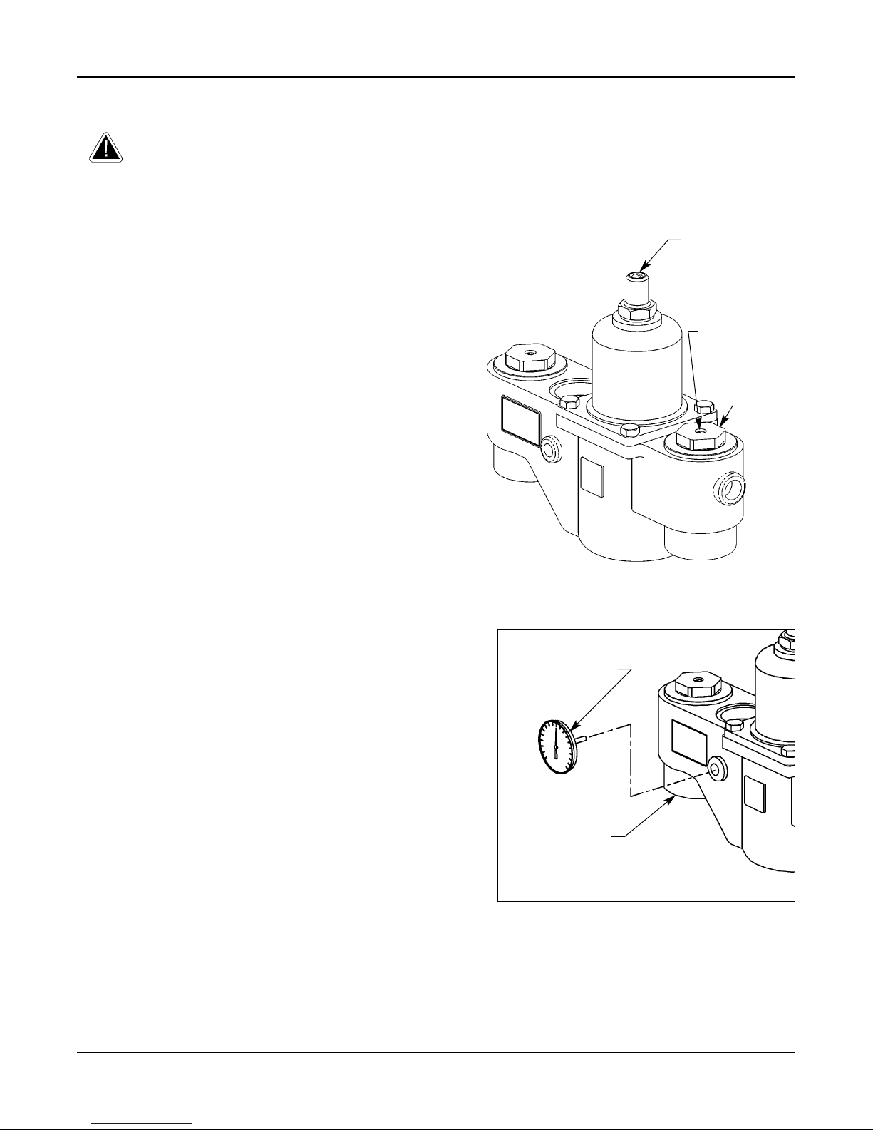
NOTE: Flush the supply lines before beginning
installation.
NOTE: When the check valves are in the OPEN
(operating) position, the cover screw for the
stop/check stem will be flush with the valve cap
(see Figure 1).
1. Connect the hot and cold valve supply inlets
to the appropriate hot and cold supply piping.
2. Connect the mixed valve supply outlet from
the valve to the tempered supply piping.
3. Screw the thermometer into the hole in the
valve body (see Figure 2). The thermometer
provides a readout of the outlet water
temperature.
4. Pressurize the thermostatic mixing valve and
check for pipe leaks.
5. Slowly open the outlet valve to fill the piping
system.
6. Check the temperature when approximately
10 GPM water flow is reached (equivalent to
four standard showers) and adjust if necessary
(the range of the valve is 90°F–120°F
(32°C–49°C). To adjust the temperature, follow
the procedure below:
• remove the slotted cover screw to expose the
set screw
• using a 5/32" hex-head Allen key, turn the set
screw counterclockwise to increase the temperature or clockwise to decrease the temperature.
7. Shut the hot water inlet off by closing either the
hot water check valve or inlet valve. While the
hot water supply is turned off, check to make
sure the cold water is reduced to less than 2
GPM. If the cold water is reduced properly,
reopen the hot water supply.
8. Shut the cold water inlet off by closing either the cold water check valve or inlet valve.
While the cold water supply is off, check to make sure that the hot water flow has shut down.
THERMOMETER
VALVE BODY
Figure 2
VALVE
CAP
Figure 1
STOP/CHECK
COVER SCREW
SLOTTED
COVER SCREW
Page 4

Bradley Thermostatic Mixing Valve (HL 200) with Optional Cabinet
Model S59-3200 Series Installation and Maintenance Instructions
4 Bradley Corporation • 215-1299 Rev. H; EN 06-9091/29/07
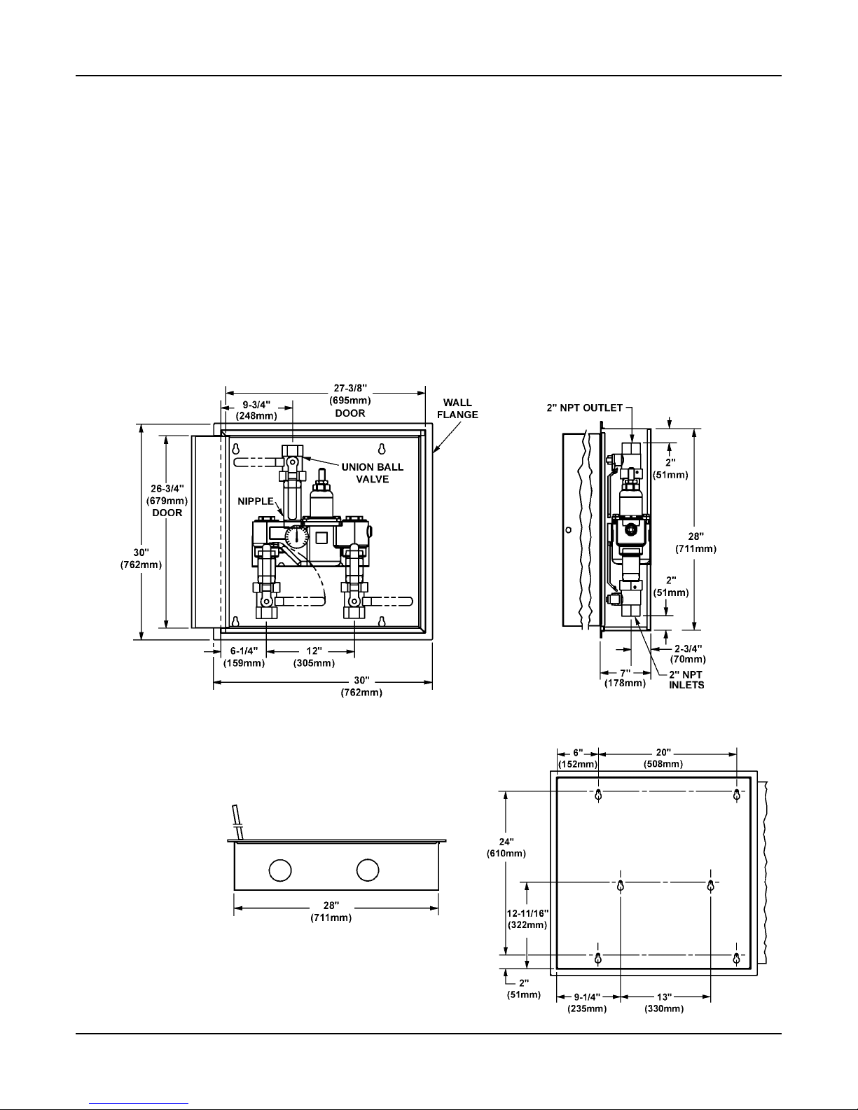
Figure 3
BOTTOM VIEW
SIDE VIEW
FRONT VIEW
Installation Instructions for Optional Recess-Mounted Cabinet
NOTE: Flush the supply lines before beginning installation.
1. Rough in a 28-1/2" W x 28-1/2" H hole in the wall for the cabinet (see Figure 3).
2. Measure and mark the cabinet mounting hole locations at the dimensions shown in Figure 3.
Install four 1/4" wall anchors, if required (anchors supplied by installer).
3. Insert the cabinet into the wall opening and secure into place with four 1/4" wall fasteners
(supplied by installer).
4. Install two anchors and screws through the valve bracket in back of the cabinet into a secure
brace (supplied by installer) or into the wall. This must be done to provide adequate support
for the valve.
5. Install the valve nipples and one-half of the union ball valve using pipe dope or teflon tape.
Then install the other half of the union ball valve onto the inlet and outlet piping.
6. Insert the valve into the bracket in the cabinet (right side of the valve goes in first). Continue
with the valve installation procedure found on page 3.
7. Position the wall flange tight to the wall and caulk in place.
Page 5
Bradley Thermostatic Mixing Valve (HL 200) with Optional Cabinet
Installation and Maintenance Instructions Model S59-3200 Series
5Bradley Corporation • 215-1299 Rev. H; EN 06-909 1/29/07
Figure 4
BOTTOM VIEW
SIDE VIEWFRONT VIEW
Installation Instructions for Optional Surface-Mounted Cabinet
NOTE: Flush the supply lines before beginning installation.
1. Measure and mark the cabinet mounting hole locations at the dimensions shown in Figure 4.
Install six 3/8" wall anchors (supplied by installer).
2. Position the cabinet onto the wall and secure into place with six 3/8" wall fasteners (supplied
by installer).
3. Install the valve nipples and one-half of the union ball valve using pipe dope or teflon tape.
Then install the other half of the union ball valve onto the inlet and outlet piping.
4. Insert the valve into the bracket in the cabinet (right side of the valve goes in first). Continue
with the valve installation procedure found on page 3.
MOUNTING HOLE LOCATIONS
Page 6

Bradley Thermostatic Mixing Valve (HL 200) with Optional Cabinet
Model S59-3200 Series Installation and Maintenance Instructions
6 Bradley Corporation • 215-1299 Rev. H; EN 06-9091/29/07
Recirculation Diagram
Recirculation Instructions
NOTE: Recirculating the water in the system provides constant regulation of the water temperature.
Flush the supply lines thoroughly after completing installation. Close off all fixtures and label
them as not in use during the recirculating process.
1. Turn off the recirculating pump and turn on the water supply (a water flow rate of 10-15
GPM is required).
2. Let the water run through the system until a consistent temperature is obtained. If you do not
obtain the required temperature, refer to procedure #6 on page 3 for temperature readjustment.
3. As soon as the water reaches the proper temperature, turn on the recirculating pump (make
certain the proper system temperature has been achieved before proceeding).
4. Check the water temperature at the return pump. If the temperature exceeds the appropriate
level by 2°F, adjust the temperature high-limit switch (this will turn off the pump). Wait until
the return water temperature is 5°F below the appropriate level and adjust the low limit
switch (this will turn the pump back on).
5. Turn the balancing valve until it is completely open.
6. Turn off all fixtures and make sure there is no water running through the system (the cold
inlet pipe should feel warm to the touch).
7. Let the system run for thirty minutes or longer without water. If, after thirty minutes, the
water temperature increases, you may readjust the temperature by slowly closing the balancing
valve until the appropriate temperature is reached.
Page 7

Bradley Thermostatic Mixing Valve (HL 200) with Optional Cabinet
Installation and Maintenance Instructions Model S59-3200 Series
7Bradley Corporation • 215-1299 Rev. H; EN 06-909 1/29/07
Thermostatic Mixing Valve Maintenance
For maximum efficiency, your thermostatic mixing valve requires a minimum amount of maintenance.
Follow the procedures outlined below to achieve highest performance.
Check the piston for smooth movement
To check the valve's piston for free and smooth move-
ment, follow the procedures outlined below:
1. Remove the valve's top cap and pull out the push rod
and then the thermostat (see Figure 5). You may use
a needlenose pliers to remove the thermostat from
the valve body if desired.
2. Insert a 7/16" dia. rod into the valve and into the piston overheat chamber. Mark the length of the rod
inside the valve (see Figure 6).
3. Push the rod until the piston stops and mark the new
length of the dowel (the new length should be
approximately 9/16" longer than the original length)
(see Figure 6). If the length of the dowel is not as it
should be, the piston is not moving freely and needs
to be cleaned along with the piston liner. Clean the
piston and liner following the method outlined
below:
• remove the control section assembly from the
valve body
• remove the top cap and thermostat
• unthread the liner from the cap (it is glued
together; the O-rings must be removed and a
propane torch may be required to melt the glue
and loosen the liner)
• any cleaner suitable for brass and stainless steel
may be used (if cleaning with suitable cleaner is
not sufficient to remove debris, a 400-grit sandpaper may be used to polish and hone the piston
and liner).
4. If the piston moves freely, push the mechanism up
and down several times to make sure the piston
moves smoothly and consistently. If movement of
the piston is not consistent, recheck the piston and
liner for dirt and debris as described in procedure #3.
• if the piston parts need to be replaced, contact
your Bradley representative and ask for
Piston/Liner Kit (part number S65-196).
WARNING: To prevent injuries, use proper protective equipment for eyes
and skin when using a propane torch.
THERMOSTAT
Figure 5
TOP CAP
w/PUSHROD
7/16"
ROD
The second mark
should be 9/16"
higher on the rod
than the first mark.
PISTON
OVERHEAT
CHAMBER
Figure 6
Page 8

Bradley Thermostatic Mixing Valve (HL 200) with Optional Cabinet
Model S59-3200 Series Installation and Maintenance Instructions
8 Bradley Corporation • 215-1299 Rev. H; EN 06-9091/29/07
Thermostatic Mixing Valve Maintenance continued . . .
Check the thermostat for proper operation
To check the valve's thermostat for proper operation,
follow the procedures outlined below.
1. Remove the top cap and pull out the push rod and
thermostat (see Figure 5 on page 7).
2. Insert a 7/16" dia. rod into the thermostat bellows.
Mark the length of the rod inside the bellows (see
Figure 7).
3. Use a marking pen to mark the thermostat bellows
length (at room temperature, with 10 lb. of force,
the bellows length should be approximately 2.6")
(see Figure 7).
4. If the thermostat bellows length is not in the proper
range, the thermostat must be replaced (it cannot be
repaired). Contact your Bradley representative and
ask for Thermostat Kit (part number S65-194).
Adjust the temperature
To adjust the valve's temperature to other than the factory
preset, follow the procedures outlined below.
1. Turn on the water and let it run until at least 10
GPM is flowing through the valve.
2. Remove the slotted cover screw to expose the set
screw.
3. Using a 5/32" hex-head Allen key, turn the set screw counterclockwise to increase the
temperature or clockwise to decrease the temperature.
4. When the adjustment is complete, replace the cover screw and turn off the water.
Thermostatic Mixing Valve Troubleshooting
NOTE: Before attempting to troubleshoot the valve or disassemble the components, check for the
following conditions:
• make sure that the check valves are fully open (the slotted stem must be flush with the
stop/check cap) (see Figure 1 on page 3) and that all inlet and outlet shut-off valves are open
• make sure that the hot and cold inlet pipes are connected properly, and that there are no
cross-connections or leaking stop/check valves
• check the hot water heater output to make sure that it is at least 15° F above the set
temperature.
Be sure to close the appropriate shut-off valves prior to disassembly of the valve and reopen the
valves after inspection and repair is complete.
Problem: No water flow
Cause: The thermostat has failed and subsequently, the safety shut-off has engaged.
Solution: See "Check the thermostat for proper operation" above and follow the step-by-step
procedure.
7/16"
ROD
Bellows length
should be 2-1/2"
to 2-3/4"
Figure 7
THERMOSTAT
Page 9

Bradley Thermostatic Mixing Valve (HL 200) with Optional Cabinet
Installation and Maintenance Instructions Model S59-3200 Series
9Bradley Corporation • 215-1299 Rev. H; EN 06-909 1/29/07
Thermostatic Mixing Valve Troubleshooting continued . . .
Problem: Limited water flow
Cause: The stop and check sections of the valve do not
move freely.
Solution: Dirt and debris have collected on the check
screen or seat, limiting the movement of the
stop and checks. Remove the stop and checks,
clean the screen and seat and reassemble the
valve (see Figure 8). Do not remove the seat.
The components may be scraped with a screwdriver to remove debris. Apair of tweezers
works well for pulling debris out from the seat.
If the stop and checks need to be replaced,
contact your Bradley representative and ask for
Check/Stop Kit (part number S65-190).
Problem: Improper water temperature
Cause: Valve temperature is not properly set.
Solution: See "Adjust the temperature" on page 8 and
follow the step-by-step procedure.
Problem: External leaks in the system
Cause: Either the NPT joints or O-rings have been damaged.
Solution: Replace the O-rings where necessary. For
replacement of O-rings, contact your Bradley
representative and ask for O-Ring/Seal Kit (part
number S65-195).
Problem: Temperature fluctuation
Cause: Thermostat is slowly failing.
Solution: See "Check the thermostat for proper operation" on page 8 and follow the step-by-step
procedure.
Cause: Recirculation is not balanced.
Solution: See "Recirculation instructions" on page 6 and follow the step-by-step procedure.
Cause: Inlet supply line to the mixing valve is being shared by other pieces of equipment that are
used only periodically, such as laundry appliances or washdown stations. It may reduce
the inlet pressure to the mixing valve to less than 10 PSI. The supply line size may not be
large enough to supply both the valve and the other appliances.
Solution: Enlarge the supply line size, reconfigure the supply line or regulate the supply usage.
STOP AND
CHECKS
Figure 8
VALVE SEAT
VALVE
SCREEN
Page 10

Bradley Thermostatic Mixing Valve (HL 200) with Optional Cabinet
Model S59-3200 Series Installation and Maintenance Instructions
10 Bradley Corporation • 215-1299 Rev. H; EN 06-9091/29/07
S59-3200 Parts Breakdown and Service Kits
O-Ring Kit S65-195
Item Qty. Description
2 1 O-Ring
14 1 O-Ring
15 1 O-Ring
16 1 O-Ring
19 1 O-Ring
23 2 O-Ring
31 2 O-Ring
33 2 O-Ring
Piston & Liner Kit S65-196
Item Qty. Description
2 1 O-Ring
3 1 Liner
4 1 Washer
5 1 Screw
6 1 Spring
7 1 Lower Chamber
8 1 Spring
9 1 Washer
10 1 Piston
11 1 Upper Chamber
Thermostat Kit S65-194
Item Qty. Description
12 1 Thermostat
14 1 O-Ring
19 1 O-Ring
Center Section Kit S65-302
Item Qty. Description
2 1 O-Ring
3 1 Liner
4 1 Washer
5 1 Screw
6 1 Spring
7 1 Lower Overheat
Chamber
8 1 Spring
9 1 Washer
10 1 Piston
11 1 Upper Overheat
Chamber
12 1 Thermostat
13 1 Pushrod
14 1 O-Ring
15 1 O-Ring
16 1 O-Ring
17 1 Control Cap
18 4 Bolt
19 1 O-Ring
20 1 Top Cap
21 1 Set Screw
22 1 Screw
Check/Stop Kit S65-190
Item Qty. Description
23 2 O-Ring
24 2 Seat
25 2 Nut
26 2 Washer
27 2 Seal
28 2 Holder (for Seal)
29 2 Spring
30 2 Strainer
31 2 O-Ring
32 2 Stem
33 2 O-Ring
34 2 Cap
NOTE: Kit numbers for rough brass finish
and standard range thermostat. Contact
Bradley for other configurations.
Washer/Seal Kit S65-321
Item Qty. Description
4 1 Washer
9 1 Washer
26 2 Washer
27 2 Seal
 Loading...