

Page 1
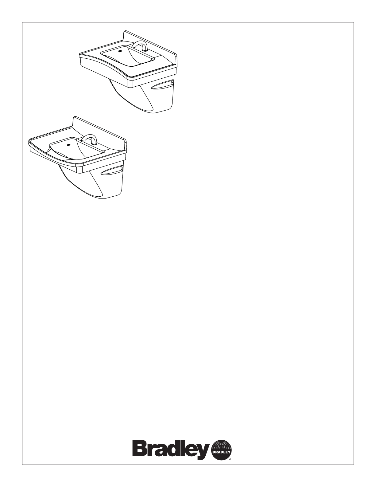
Installation
FL-1L
FL-1H
FL-1H, FL-1L
Frequency® Lavatory System
Système de lavabos Frequency
Sistema de lavabo Frequency
U.S. Pat. No. Des. 507,634
Table of Contents
Pre-Installation Information . . . . . . . . . . . . . . . . . . . . . . . . . . . . . . 2
Components . . . . . . . . . . . . . . . . . . . . . . . . . . . . . . . . . . . . . . . . . 3
Dimensions . . . . . . . . . . . . . . . . . . . . . . . . . . . . . . . . . . . . . . . . 4–5
Rough-ins . . . . . . . . . . . . . . . . . . . . . . . . . . . . . . . . . . . . . . . . . . . 6
Lavatory Mounting . . . . . . . . . . . . . . . . . . . . . . . . . . . . . . . . . . . . . 7
Drain and Tailpiece . . . . . . . . . . . . . . . . . . . . . . . . . . . . . . . . . . . . 8
Faucet Battery Box . . . . . . . . . . . . . . . . . . . . . . . . . . . . . . . . . . . . 8
Optional Tankless Water Heater . . . . . . . . . . . . . . . . . . . . . . . . . . 8
P-trap and Trap Cover . . . . . . . . . . . . . . . . . . . . . . . . . . . . . . . . . . 9
Cleaning and Maintenance Instructions for Terreon . . . . . . . . . . . 9
Table des matières
Avant l’installation . . . . . . . . . . . . . . . . . . . . . . . . . . . . . . . . . . . . 10
Composants . . . . . . . . . . . . . . . . . . . . . . . . . . . . . . . . . . . . . . . . 11
Dimensions . . . . . . . . . . . . . . . . . . . . . . . . . . . . . . . . . . . . . . 12–13
Mises en place des canalisations . . . . . . . . . . . . . . . . . . . . . . . . 14
Lavabo . . . . . . . . . . . . . . . . . . . . . . . . . . . . . . . . . . . . . . . . . . . . . 15
Drain et raccord droit de vidange . . . . . . . . . . . . . . . . . . . . . . . . 16
Compartiment des piles de robinets . . . . . . . . . . . . . . . . . . . . . . 16
Chauffage d’eau sans réservoir en option . . . . . . . . . . . . . . . . . . 16
Siphon et Couvercles . . . . . . . . . . . . . . . . . . . . . . . . . . . . . . . . . 17
Instructions de nettoyage et d’entretien pour Terreon . . . . . . . . . 17
®
®
215-1511 Rev. E; ECM 09-11-0006
© 2009 Bradley Corporation
Page 1 of 25 7/14/09
Contenido
Información previa a la instalación . . . . . . . . . . . . . . . . . . . . . . . 18
Componentes . . . . . . . . . . . . . . . . . . . . . . . . . . . . . . . . . . . . . . . 19
Dimensiones . . . . . . . . . . . . . . . . . . . . . . . . . . . . . . . . . . . . . 20–21
Colocación de tuberías empotradas . . . . . . . . . . . . . . . . . . . . . . 22
Montaje del lavabo . . . . . . . . . . . . . . . . . . . . . . . . . . . . . . . . . . . 23
Desagüe y pieza inferior . . . . . . . . . . . . . . . . . . . . . . . . . . . . . . . 24
Caja de batería de la llave . . . . . . . . . . . . . . . . . . . . . . . . . . . . . . 24
Calentador de agua sin tanque opcional . . . . . . . . . . . . . . . . . . . 24
Sifón y cubiertas . . . . . . . . . . . . . . . . . . . . . . . . . . . . . . . . . . . . . 24
Instrucciones de limpieza y mantenimiento para Terreon . . . . . . 25
P.O. Box 309, Menomonee Falls, WI USA 53052-0309
PHONE 800.BRADLEY (800.272.3539) FAX 262.251.5817
bradleycorp.com
Page 2
FL-1H, FL-1L Installation
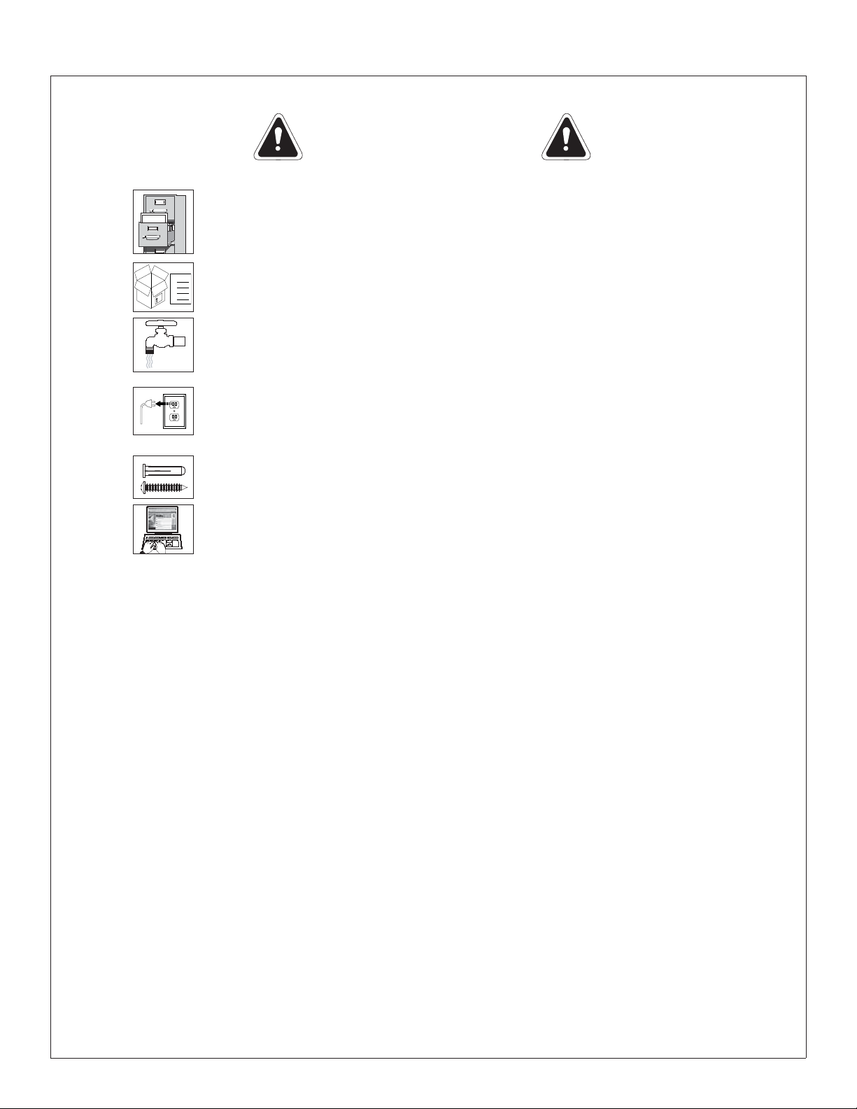
IMPORTANT!
Read this entire installation manual to ensure proper installation.
Installation
THIS
SIDE
UP
When finished with the installation, file this manual with the owner or
maintenance department. Compliance and conformity to local codes
and ordinances is the responsibility of the installers.
Packing List
Separate parts from packaging and make sure all parts are accounted
•
•
for before discarding any packaging material. If any parts are
•
•
missing, do not begin installation until you obtain the missing parts.
Make sure that all water supply lines have been flushed and then
completely turned off before beginning installation. Debris in supply
lines can cause valves to malfunction.
Turn OFF electrical power to the electrical outlets, then unplug all
electrical units prior to installation. Electrical power MUST remain off
until installation is complete. After installation is complete, turn on
the water supply fi rst, then turn on the electrical power.
Hardware provided by installer must be appropriate for wall
construction. Wall anchors must have a minimum pull-out rating of
1,000 lbs.
Product warranties may be found under “Products” on our Web site
at bradleycorp.com.
Supplies Required:
• (4) 3/8" wall anchors, bolts and 1" min. O.D. washers to mount main frame and bowl to wall (minimum pull-out rating of
1,000 lbs.)
• (2) #10 wall anchors (for optional mixing valve/bracket mounting)
• 1/2" NPT hot/cold or tempered supply piping
• 1-1/2" NPT drain piping
• OPTIONAL: 110 volt GFCI protected electrical outlet for 100–120 VAC plug-in transformer (for Bradley Faucets)
• OPTIONAL: 240/208 or 277 volts for electric tankless water heater
2 7/14/09 Bradley Corporation • 215-1511 Rev. E; ECM 09-11-0006
Page 3
Installation FL-1H, FL-1L
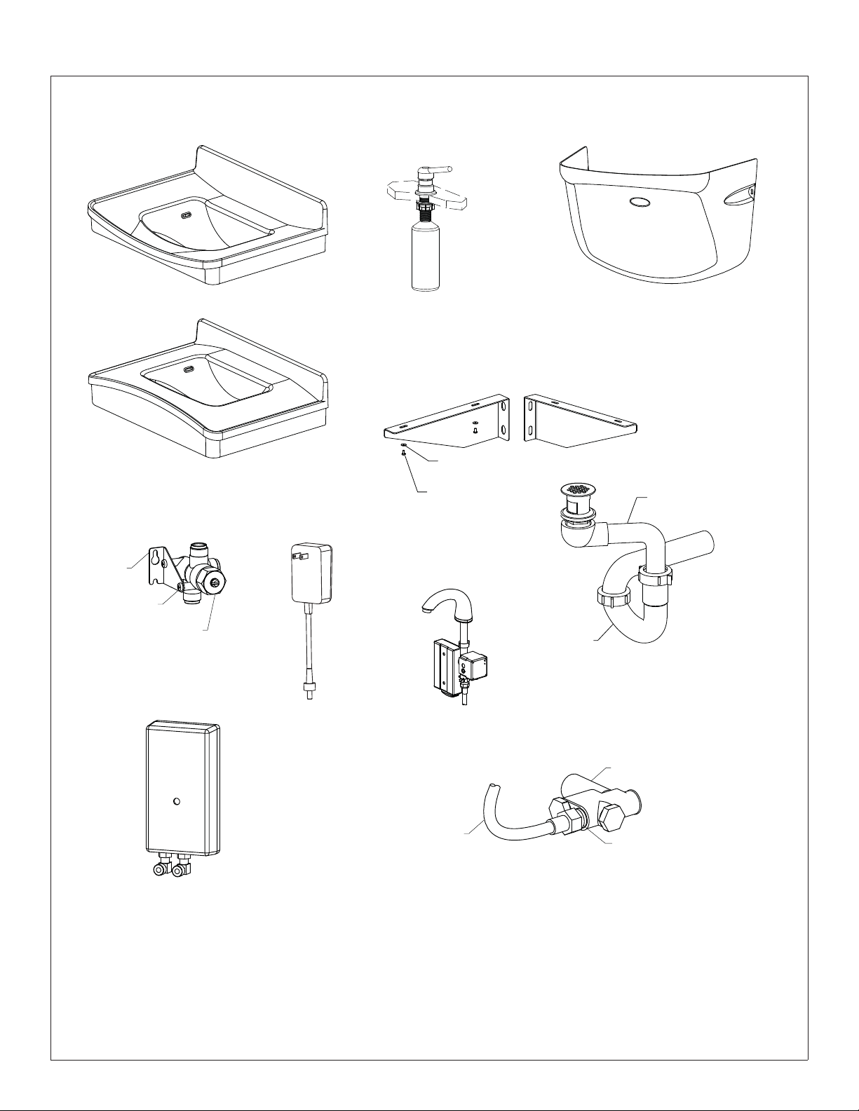
Components
Bowl FL-1L (187-273)
Contact Bradley for
color options
Soap Dispenser
Model 6334
Prepack Trap Cover FL-1
(S45-2108 - Gray)
(S45-2108A - Putty)
(S45-2108B - Coal)
Bowl FL-1H (187-274)
Contact Bradley for
color options
Vernatherm™
TMV Assembly
Bracket
(140-934)
Screw
(P18-054)
(S01-524)
Valve
Optional
Single-Unit
Adapter
(153-443)
Support Bracket
(140-823L)
#10 Washer
(142-002AT)
#10-24 Screw
(P18-054)
Aerada™ 1200 Series
CS Faucet
Model S53-315
Optional
Tempered Line
Support Bracket
(140-823R)
Offset Strainer
(269-1751)
P-Trap
(269-1697)
Stop/Strainer/Check
Valve (S60-003)
1/2" Flex Hose
(269-653)
1/2" Nipple
(113-006DH)
Optional Tankless Water Heater
(269-1765 - EX55TMLB, 240/208 volts)
(269-1766 - EX60TMLB, 277 volts)
Bradley Corporation • 215-1511 Rev. E; ECM 09-11-0006 7/14/09 3
Page 4
FL-1H, FL-1L Installation
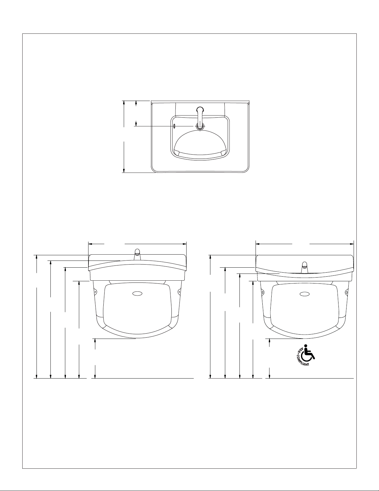
Dimensions - Front and Top Views
FL-1H shown
FL-1L is similar
7¾"
(197mm)
22"
(559mm)
FL-1L FL-1H
30"
(762mm)
37¾"
(959mm)
36"
(914mm)
34"
(864mm)
30"
(762mm)
12¼"
(311mm)
(959mm)
30"
(762mm)
37¾"
34" ADA
(864mm)
32"
(813mm)
30" ADA
(762mm)
12¼" ADA
(311mm)
4 7/14/09 Bradley Corporation • 215-1511 Rev. E; ECM 09-11-0006
Page 5
Installation FL-1H, FL-1L
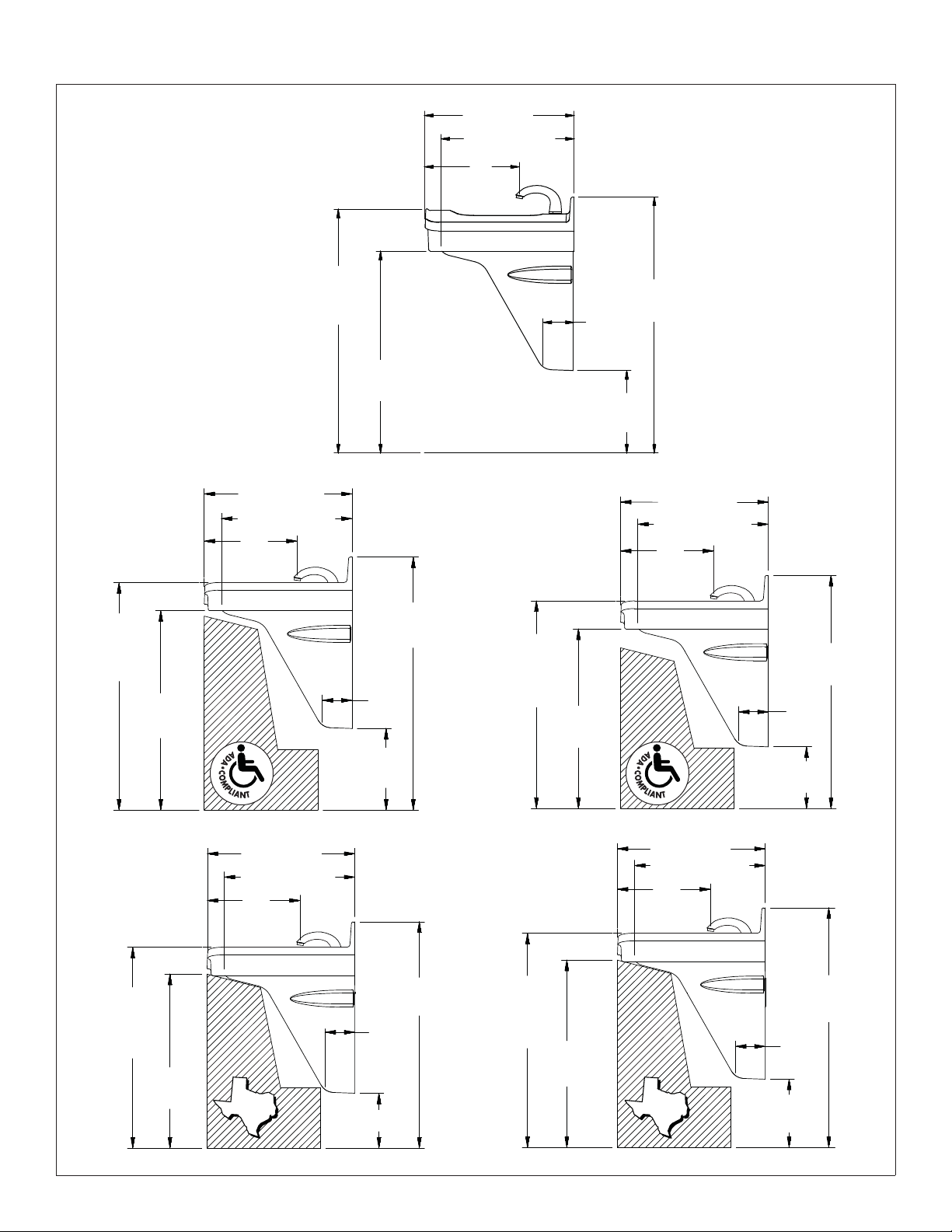
Dimensions - Side Views
FL-1L
Standard
Height
22" (559mm)
19¾" (502mm)
14"
(356mm)
FL-1H
36"
(914mm)
Rim Height
30"
(762mm)
22" (559mm)
19¾" (502mm)
14"
(356mm)
Juvenile
Height
Ages 6–12
5
⁄8"
4
(117mm)
(311mm)
37¾"
(959mm)
12¼"
22" (559mm)
19¾" (502mm)
14"
(356mm)
34"
(864mm)
Rim
Height
(762mm)
TAS Height
Grades Pre-K
through 5 or 6
30"
(762mm)
Rim
Height
30"
26"
(660mm)
22" (559mm)
19¾" (502mm)
14"
(356mm)
TAS
(959mm)
45⁄8"
(117mm)
12¼"
(311mm)
(857mm)
5
⁄8"
4
(117mm)
8¼" (210mm)
37¾"
33¾"
31"
(787mm)
Rim
Height
(686mm)
TAS Height
Grades 6 through
8 or 9
32"
(813mm)
Rim
Height
28"
(711mm)
27"
22" (559mm)
19¾" (502mm)
14"
(356mm)
TAS
45⁄8"
(117mm)
9¼"
(235mm)
5
⁄8"
4
(117mm)
10¼"
(260mm)
34¾"
(883mm)
35¾"
(908mm)
Bradley Corporation • 215-1511 Rev. E; ECM 09-11-0006 7/14/09 5
Page 6
FL-1H, FL-1L Installation
1
FL-1H
FL-1L
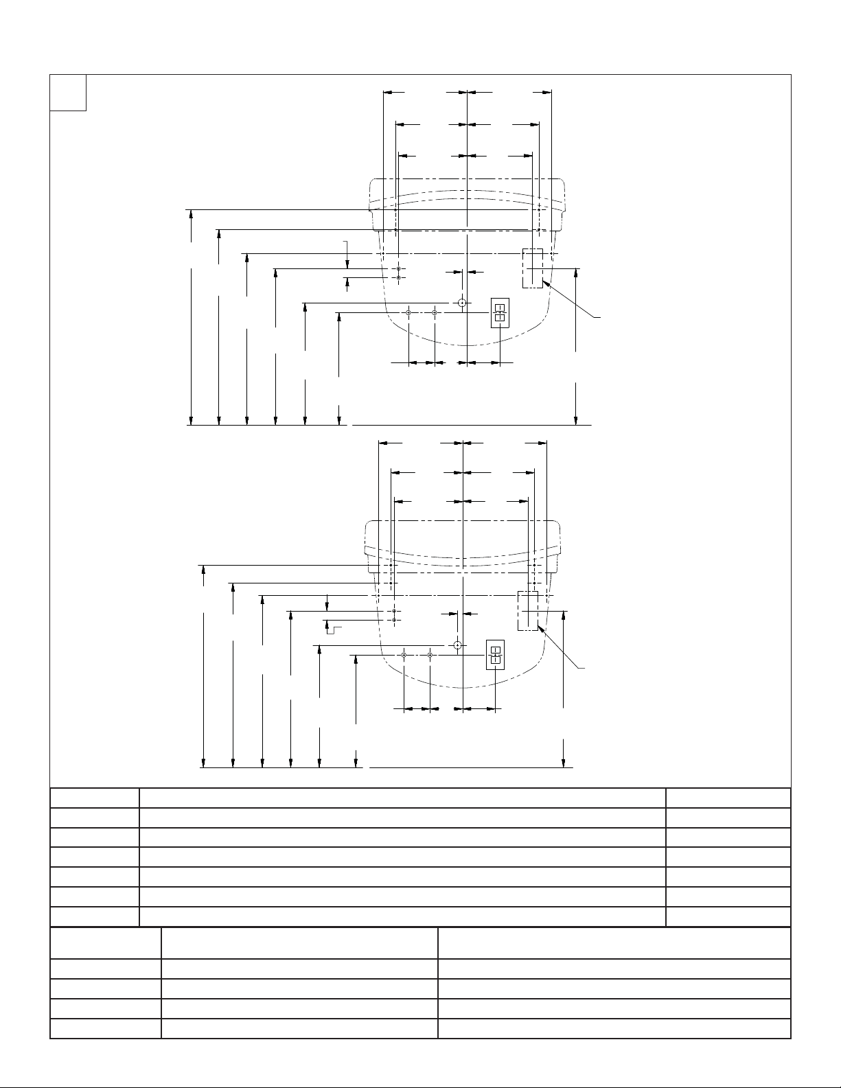
Rough-Ins
33"
(838mm)
(762mm)
30"
(670mm)
26
3
⁄8"
(610mm)
1
24"
(476mm)
3
⁄8" (35mm)
18¾"
(432mm)
17"
A
A
B
4"
(102mm)
7
12
⁄8"
(327mm)
11"
(279mm)
10½"
(267mm)
D
D
HC
(127mm)
7
⁄8"
12
(327mm)
11"
(279mm)
10½"
(267mm)
W
5"
12
(327mm)
11"
(279mm)
10"
(254mm)
¾"
(19mm)
(127mm)
127⁄8"
(327mm)
11"
(279mm)
10"
(254mm)
7
⁄8"
A
A
B
E
Recommended 240v/208v
or 277v electrical rough-in
location (approx. 3" x 6")
5"
24"
(610mm)
A
A
B
E
Recommended 240v/208v
or 277v electrical rough-in
location (approx. 3" x 6")
5"
24"
(610mm)
31"
(787mm)
28"
(711mm)
(670mm)
26
3
⁄8"
24"
(610mm)
18¾"
(476mm)
B
3
1
⁄8" (35mm)
(102mm)
17"
A
A
D
D
H
W
C
4"
(127mm)
¾"
(19mm)
5"
(127mm)
(432mm)
CODE DESCRIPTION QTY.
A 3/8" Lav Deck Anchors with a Minimum Pull-Out Force of 1,000 lbs. 4
B #10 Wall Anchors/Fasteners for Mounting Trap Covers 2
H, C 1/2" NPT Hot/Cold Supplies, Stub-Out 2" From Wall 1
D #10 Wall Anchors/Fasteners for Valve Mounting 2
E 110v GFI Protected Electrical Outlet 1
W 1-1/2" NPT Drain, Stub-Out 2" from Wall 1
RIM HEIGHT
VERTICAL HEIGHT ADJUSTMENTS FOR CODES
A–E, H, C and W
FIXTURE STYLE
34" None Standard Height
32" Subtract 2" TAS, Grades 6 through 8 or 9
31" Subtract 3" TAS, Pre-K through Grades 5 or 6
30" Subtract 4" Juvenile Height
6 7/14/09 Bradley Corporation • 215-1511 Rev. E; ECM 09-11-0006
Page 7
Installation FL-1H, FL-1L
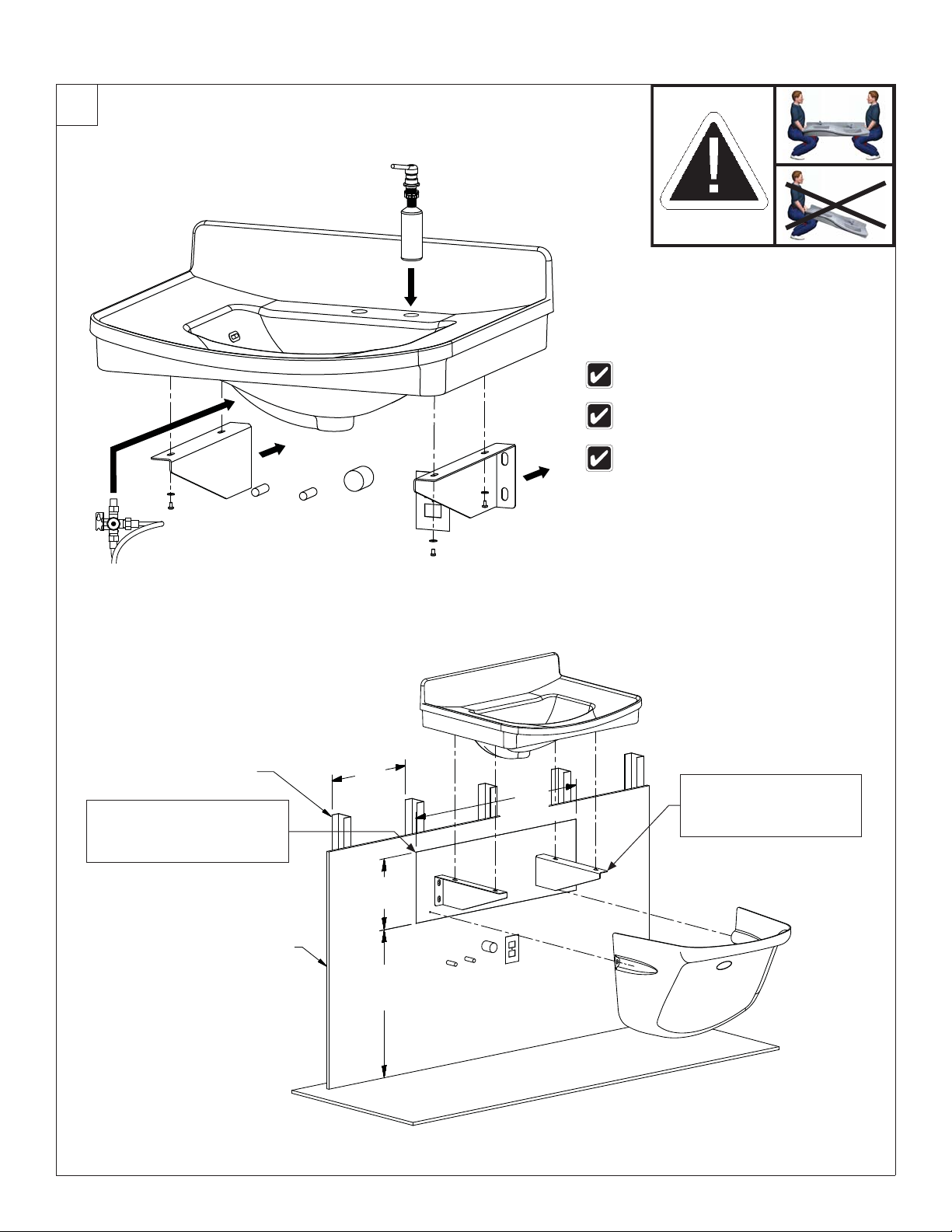
2
Lavatory Mounting
Refer to the rough-ins to determine wall
mounting location for optional mixing valve.
Installer may prefer to install the faucet
before mounting the fi xture to the wall.
If necessary, adjust the fi xture height
before securing to the support brackets.
Backing Information
Metal Studs
Securely fasten the plywood
to at least (3) metal studs
A
(plywood to equal thickness
of drywall, ½" minimum)
Drywall
16"
(406mm)
12"
(305mm)
25"
(635mm)
35"
(889mm)
Use 3⁄8" toggle bolts and
washers to secure the
B
support brackets to the
plywood (2) places.
Bradley Corporation • 215-1511 Rev. E; ECM 09-11-0006 7/14/09 7
Page 8
FL-1H, FL-1L Installation
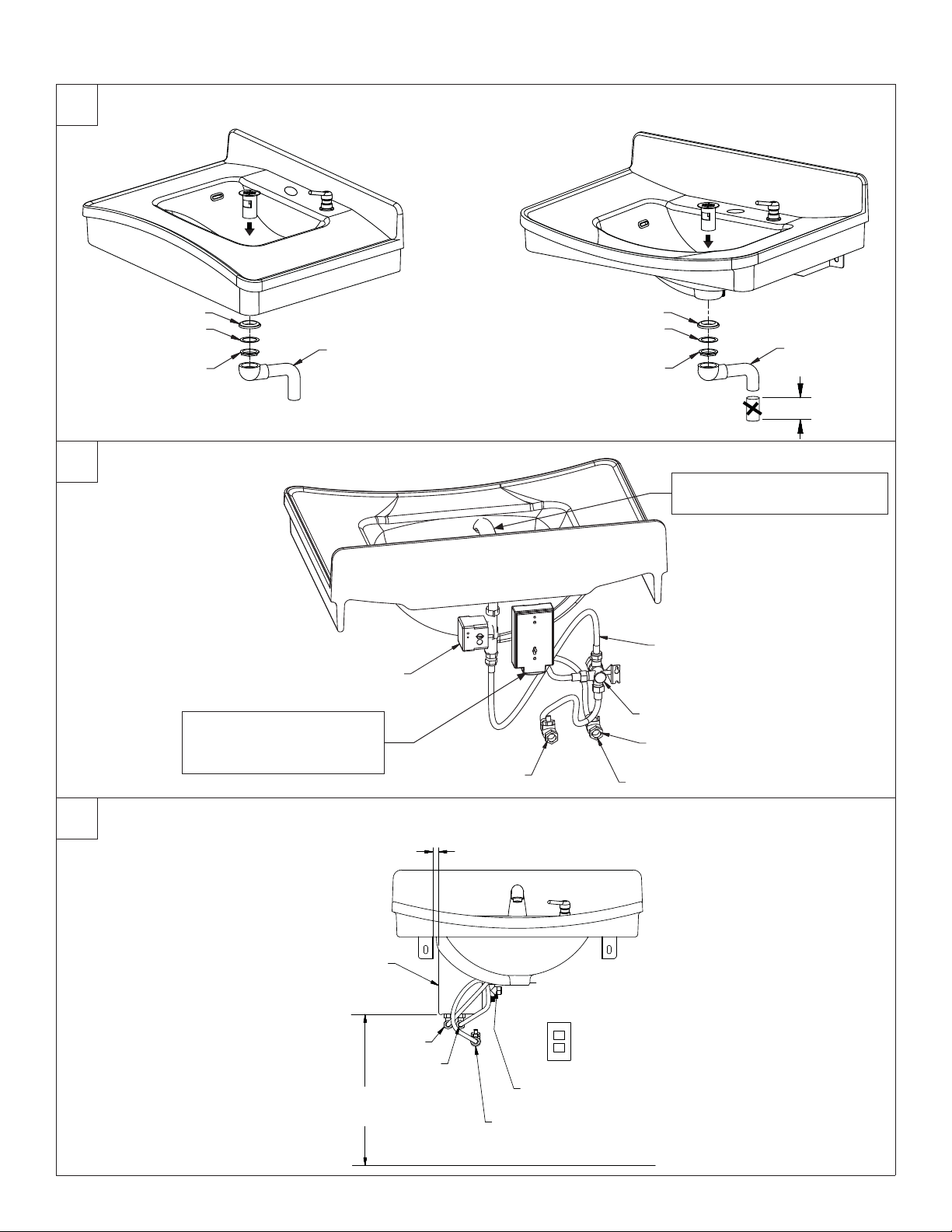
3
Drain and Tailpiece
FL-1LFL-1H
Rubber
Friction
Nut
4
Faucet Battery Box
FL-1L shown
FL-1H is similar
Mount the Faucet Battery
Box to the wall at the
A
desired location.
Tailpiece
Faucet Valve
Control Module
Cold
Rubber
Friction
Nut
B
1/2" Flexible Hose (qty. 3)
(269-1735)
Mixing Valve
Hot
Stop/Check Valve
Tailpiece
4" (102mm)
Install the faucet according to
manufacturer’s instructions.
5
Optional Tankless Water Heater
¾" (19mm)
FL-1L shown
FL-1H is similar
Electric Tankless
Water Heater
Outlet
Inlet
20"
(508mm)
Faucet Inlet
Stop/Check Valve,
Cold Supply Outlet
8 7/14/09 Bradley Corporation • 215-1511 Rev. E; ECM 09-11-0006
Page 9

Installation FL-1H, FL-1L
6
P-Trap and Trap Cover
FL-1L shown
FL-1H is similar
Cleaning and Maintenance for Terreon
Material Description: Terreon is an NAHB Certifi ed densifi ed solid surface material composed of polyester resin and is resistant
to chemicals, stains, burns and impact. Surface damage can be easily repaired with everyday cleansers or fi ne grit abrasives.
Routine Cleaning: Clean daily or as often as conditions require using a standard commercial or household cleaner such as
Formula 409
Stubborn Stains: Remove tough stains with Ajax
circular motion with 240 grit wet/dry sandpaper. The fi nish can be renewed with a maroon Scotch-Brite
®
or Windex®.
®
, Comet®, or Soft-Scrub® and a green Scotch-Brite® pad or lightly sand in a
®
pad.
Special Situations for Terreon Material
Scratches: Remove scratches with a green Scotch-Brite® pad. The fi nish can then be renewed with a maroon Scotch-Brite®
pad, followed by a white Scotch-Brite
Hard Water Deposits: Remove hard water deposits with a mild solution of vinegar and water. Always rinse the unit
thoroughly after cleaning.
Restoring the surface: Use Hope’s
material. Bradley recommends additional care and maintenance for the darker colored Terreon. For additional information,
visit bradleycorp.com.
Do not use strong acid or alkaline chemicals and cleansers to clean Terreon. If these chemicals come in
contact with the surface, wipe them off immediately and rinse with soapy water. Avoid contact with harsh
chemicals such as paint remover, bleach, acetone, etc. Avoid contact with hot pans and objects.
Repair Kits: Terreon repair kits are available. Contact your Bradley representative or distributor for part numbers and pricing
Repair kits are made to order and have a shelf life of 30 days.
Terreon is a unique, cast solid surface material. Aggregate fl ow and distribution as well as shades of color can vary from
product to product creating natural characteristics.
Brand Names: Use of brand names is intended only to indicate a type of cleaner. This does not constitute an endorsement,
nor does the omission of any brand name cleaner imply inadequacy. Many products named are regional in distribution, and
can be found in local supermarkets, department and hardware stores, or through your cleaning service. It is emphasized that
all products should be used in strict accordance with package instructions.
®
pad or 30-micron sandpaper.
®
Solid Surface cleaner and polish to refresh and protect the Terreon Solid Surface
Bradley Corporation • 215-1511 Rev. E; ECM 09-11-0006 7/14/09 9
Page 10

FL-1H, FL-1L Installation
IMPORTANT !
Lire ce manuel d’installation dans son intégralité pour garantir une installation
Installation
THIS
SIDE
UP
appropriée. Une fois celle-ci terminée, classer ce manuel auprès du service à
la clientèle ou d’entretien. L’installateur est responsable de la conformité de
l’installation aux codes pour des drain et codes et règlements en vigueur.
Packing List
Assurez-vous que toutes les pièces sont incluses dans l’emballage et qu’il n’en
•
•
manque aucune avant de jeter l’emballage. Ne commencez pas l’assemblage avant
•
•
de recevoir les pièces manquantes.
Veiller à bien vidanger et fermer toutes les conduites d’eau avant de commencer
l’installation. Tout débris dans les conduites d’alimentation risque de provoquer un
mauvais fonctionnement des soupapes.
Couper toute alimentation électrique aux prises électriques puis débrancher
toutes les unités électriques avant l’installation. L’alimentation électrique DOIT
être coupée jusqu’à ce que l’installation soit terminée. Une fois l’installation
terminée, ouvrir d’abord l’alimentation en eau puis mettre en marche l’alimentation
électrique.
La quincaillerie fournie par l’installateur doit être appropriée pour la construction
des murs. Les dispositifs d’ancrage muraux doivent avoir un indice d’arrachement
minimum de 1,000 lb (453,6 kg).
Les garanties de produits figurent sous la rubrique « produits » sur notre site
Internet à bradleycorp.com.
Equipements nécessaires :
• (4) dispositifs d’ancrage muraux de 3⁄8", boulons et rondelles de D.E. de 1" mini. pour monter bâti principal et lavabo
sur le mur (indice d’arrachement minimum de 453,6 kg/1 000 lb)
• (2) dispositifs d’ancrage muraux n° 10 (pour robinet mitigeur/support de fi xation en option)
• Conduites d’alimentation d’eau chaude et d’eau froide ou d’eau tempérée ½" NPT
• Canalisation de drain 1½" NPT
• EN OPTION : Prise électrique protégée 110 volts GFCI pour transformateur à brancher 100–120 V c.a. (pour
robinets Bradley)
• EN OPTION : 240/208 ou 277 volts pour chauffage d’eau électrique sans réservoir
10 7/14/09 Bradley Corporation • 215-1511 Rev. E; ECM 09-11-0006
Page 11

Installation FL-1H, FL-1L
Composants
Lavabo FL-1L (187-273)
contacter Bradley pour
les options de couleur
Distributeur de savon
Modèle 6334
Patte de support
(140-823L)
Paquet de couvercle de siphon FL-1
(S45-2108 - Gray)
(S45-2108A - Putty)
(S45-2108B - Coal)
Patte de support
(140-823R)
Lavabo FL-1H (187-274)
contacter Bradley pour
les options de couleur
Vernatherm™ TMV
Support
(140-934)
Vis
(P18-054)
Soupape
(S01-524)
Ensemble
Adaptateur
d’unité simple
en option
(153-443)
Rondelle #10
(142-002AT)
Vis #10-24
(P18-054)
Robinet Aerada™
1200 Série CS
Modèle S53-315
Tuyau fl exible 1/2"
(269-653)
Crépine en déport
(269-1751)
Siphon en P
(269-1697)
Conduite trempée
en option
Arrêt/Crépine/Non-retour
(S60-003)
Raccord 1/2"
(113-006DH)
Chauffage d’eau sans réservoir en option
(269-1765 - EX55TMLB, 240/208 volts)
(269-1766 - EX60TMLB, 277 volts)
Bradley Corporation • 215-1511 Rev. E; ECM 09-11-0006 7/14/09 11
Page 12

FL-1H, FL-1L Installation
Dimensions - Vues de face et de dessus
FL-1H est montrée
FL-1L est similaire
7¾"
(197mm)
22"
(559mm)
FL-1L FL-1H
30"
(762mm)
37¾"
(959mm)
36"
(914mm)
34"
(864mm)
30"
(762mm)
12¼"
(311mm)
(959mm)
30"
(762mm)
37¾"
34" ADA
(864mm)
32"
(813mm)
30" ADA
(762mm)
12¼" ADA
(311mm)
12 7/14/09 Bradley Corporation • 215-1511 Rev. E; ECM 09-11-0006
Page 13

Installation FL-1H, FL-1L
Dimensions - Vues latérales
36" (914mm)
FL-1L
Hauteur
standard
22" (559mm)
19¾" (502mm)
14"
(356mm)
FL-1H
Hauteur de
bord
30"
(762mm)
22" (559mm)
19¾" (502mm)
14"
(356mm)
Hauteur
enfant
5
⁄8"
4
(117mm)
(311mm)
37¾"
(959mm)
12¼"
22" (559mm)
19¾" (502mm)
14"
(356mm)
34"
(864mm)
Hauteur
de bord
30"
(762mm)
Hauteur TAS
Niveaux scolaires
Pre-K à 5 ou 6
30"
(762mm)
Hauteur
de bord
26"
(660mm)
22" (559mm)
19¾" (502mm)
14"
(356mm)
TAS
(959mm)
45⁄8"
(117mm)
12¼"
(311mm)
(857mm)
5
⁄8"
4
(117mm)
8¼" (210mm)
37¾"
33¾"
31"
(787mm)
Hauteur
de bord
27"
(686mm)
Hauteur TAS
Niveaux scolaires 6
à 8 ou 9
32"
(813mm)
Hauteur
de bord
28"
(711mm)
22" (559mm)
19¾" (502mm)
14"
(356mm)
TAS
45⁄8"
(117mm)
9¼"
(235mm)
5
⁄8"
4
(117mm)
10¼"
(260mm)
34¾"
(883mm)
35¾"
(908mm)
Bradley Corporation • 215-1511 Rev. E; ECM 09-11-0006 7/14/09 13
Page 14

FL-1H, FL-1L Installation
1
Mises en place des canalisations
FL-1H
33"
(838mm)
30"
(762mm)
3
⁄8"
26
(670mm)
24"
(610mm)
FL-1L
3
1
⁄8" (35mm)
18¾"
(476mm)
17"
(432mm)
A
A
B
4"
(102mm)
7
⁄8"
12
(327mm)
11"
(279mm)
10½"
(267mm)
D
D
HC
(127mm)
7
12
⁄8"
(327mm)
11"
(279mm)
10½"
(267mm)
W
5"
12
(327mm)
11"
(279mm)
10"
(254mm)
¾"
(19mm)
(127mm)
12
(327mm)
11"
(279mm)
10"
(254mm)
7
⁄8"
A
A
B
E
Emplacement des mises en place
des canalisations électriques
recommandé 240 v/208 v ou 277 v
5"
7
⁄8"
24"
(610mm)
(approximativement 3" x 6")
A
A
B
E
Emplacement des mises en place
des canalisations électriques
recommandé 240 v/208 v ou 277 v
5"
24"
(approximativement 3" x 6")
(610mm)
31"
(787mm)
28"
(711mm)
(670mm)
26
3
⁄8"
24"
(610mm)
18¾"
(476mm)
B
3
1
⁄8" (35mm)
(102mm)
17"
A
A
D
D
H
W
C
4"
(127mm)
¾"
(19mm)
5"
(127mm)
(432mm)
Code Description Qté.
A Dispositifs d’ancrage 3⁄8" d’unité de lavabo avec une force d’arrachement minimum de 453,6 kg. (1 000 lb.) 4
B Dispositifs d’ancrage muraux n° 10/Fixations pour monter siphon/Couvercles 2
H, C Conduites d’alimentation d’eau froide/chaude ½" NPT, tubulures de raccordement 2" du mur 1
D Dispositifs d’ancrage muraux n° 10/Fixations pour montage de robinet 2
E Prise électrique protégée 110 v GFI 1
W Drain 1½" NPT, tubulure de raccordement 2" du mur 1
Hauteur de bord
Réglages de hauteur verticale pour codes A–E, H,
C et W
Style d’appareils sanitaires
34" 0 Hauteur standard
32" Soustraire 2" Hauteur TAS Niveaux scolaires 6 à 8 ou 9
31" Soustraire 3" Hauteur TAS Niveaux scolaires Pre-K à 5 ou 6
30" Soustraire 4" Hauteur enfant
14 7/14/09 Bradley Corporation • 215-1511 Rev. E; ECM 09-11-0006
Page 15

Installation FL-1H, FL-1L
2
Lavabo
Consulter les mises en place de canalisations
pour déterminer l’emplacement de fi xation sur le
mur pour un robinet mitigeur en option.
L’installateur peut préférer installer le robinet
avant de monter l’appareil sanitaire sur le mur.
Le cas échéant, ajuster la hauteur de l’appareil
sanitaire avant de fi xer aux pattes de support.
Information relative au support
Poteaux métalliques
Solidement fi xer le contreplaqué à au
moins trois (3) poteaux métalliques
A
(contreplaqué égal à épaisseur de
cloison sèche, ½" [1,3 cm] minimum)
Cloison sèche
16"
(406mm)
12"
(305mm)
25"
(635mm)
35"
(889mm)
Utiliser les boulons à ailettes
3
⁄8" et les rondelles pour
fi xer les pattes de support
B
au contreplaqué deux (2)
emplacements.
Bradley Corporation • 215-1511 Rev. E; ECM 09-11-0006 7/14/09 15
Page 16

FL-1H, FL-1L Installation
3
Drain et raccord droit de vidange
FL-1LFL-1H
CaoutchoucCaoutchouc
Friction
Raccord droit de vidange
Écrou
4
Compartiment des piles de robinets
FL-1L est montrée
Friction
Écrou
Installer les robinets
conformément aux
B
instructions du fabricant.
Raccord droit
de vidange
4" (102mm)
FL-1H est similaire
Module de contrôle de
soupapes de robinets
Monter les compartiments des
piles de robinets sur le mur aux
A
emplacements souhaités.
5
Chauffage d’eau sans réservoir en option
FL-1L est montrée
FL-1H est similaire
Chauffage d’eau
sans réservoir
20"
(508mm)
Sortie
Entrée
Sol fi ni
Froid
¾" (19mm)
Entrée de robinet
Arrêt/crépine/non-retour, sortie
d’alimentation en eau froide
Tuyau flexible ½" (qté 3)
Robinet thermostatique mélangeur
(269-1735)
Chaud
Arrêt/crépine/non-retour
16 7/14/09 Bradley Corporation • 215-1511 Rev. E; ECM 09-11-0006
Page 17

Installation FL-1H, FL-1L
6
Siphon et Couvercles
FL-1L est montrée
FL-1H est similaire
Instructions de nettoyage/d’entretien pour Terreon
Description du matériau : Terreon est un matériau de surface massif densifi é certifi é NAHB composé de résine de polyester et résistant
aux produits chimiques, aux taches, aux brûlures et à l’impact. Les dommages de surface peuvent être facilement réparés à l’aide de produits
nettoyants ordinaires ou d’abrasifs à grains fi ns.
Nettoyage de routine : Nettoyer tous les jours ou aussi souvent que les conditions l’exigent à l’aide d’un nettoyant ménager ou commercial
standard tel que Formula 409® ou Windex®.
Taches incrustées : Éliminer les taches incrustées avec Ajax®, Comet® ou Soft-Scrub® et un tampon vert Scotch-Brite® ou poncer légèrement
d’un mouvement circulaire avec du papier de verre mouillé/sec 240 grains. Le fi ni peut être renouvelé avec un tampon bordeaux Scotch-Brite.
Situations spéciales de matériau
Rayures : Retirer les rayures avec un tampon vert Scotch-Brite. Le fi ni peut être renouvelé avec un tampon bordeaux Scotch-Brite.
Dépôts d’eau dure : Retirer les dépôts d’eau dure avec une solution douce d’eau et de vinaigre. Toujours rincer l’unité à fond après tout
nettoyage.
Restauration de la surface : Utiliser le nettoyant pour surfaces massives Hope’s® et polir pour rafraîchir et protéger le matériau de
surface massive Terreon. Bradley recommande des soins et un entretien supplémentaires pour le Terreon de couleur plus foncée, pour des
instructions complètes sur cet entretien additionnel, consulter www.bradleycorp.com.
Ne pas utiliser de produits chimiques ou de nettoyants acides forts ou alcalins pour nettoyer le Terreon. Si ces produits
chimiques entraient en contact avec la surface en Terreon, les essuyer immédiatement et rincer à l’eau savonneuse. Éviter
tout contact avec des produits chimiques durs tels que du décapant, de l'eau de javel, de l’acétone, etc. éviter tout contact
avec des casseroles et des objets chauds.
Kits de réparation : Des kits de réparation Terreon sont disponibles. Contacter le représentant ou le distributeur Bradley pour obtenir des
références et des prix. Les kits de réparation sont faits sur commande et ont une durée de validité de 30 jours.
Terreon est un matériau de surface unique fondu massif. La coulée et la répartition des granulats ainsi que les nuances de couleur
peuvent varier d'un produit à l'autre créant ainsi des caractéristiques naturelles.
Marques commerciales : L’utilisation de marques commerciales n’est destinée qu’à indiquer un type de nettoyant. Ceci ne constitue
aucunement un témoignage publicitaire de même que toute omission d’un nettoyant d’une marque commerciale quelconque n’implique
son ineffi cacité. De nombreux produits sont distribués par région et peuvent se trouver dans les supermarchés locaux, grands magasins et
quincailleries, ou par le biais d’un service de nettoyage. Il est à souligner que tous les produits doivent être utilisés en stricte conformité avec
les instructions fi gurant sur l’emballage.
Bradley Corporation • 215-1511 Rev. E; ECM 09-11-0006 7/14/09 17
Page 18

FL-1H, FL-1L Installation
¡IMPORTANTE!
Lea en su totalidad este manual de instalación para garantizar una instalación
Installation
THIS
SIDE
UP
adecuada. Una vez que termine la instalación, entregue este manual al propietario
o al Departamento de Mantenimiento. Es responsabilidad de quien instale el
equipo cumplir con los códigos para desagüe y otra códigos y ordenanzas locales.
Separar todas las piezas del material de embalaje y asegurarse que todas las
Packing List
•
piezas estén incluídas antes de desechar cualquier material de embalaje. Si faltase
•
•
alguna pieza, no intentar instalar la unidad combinada Bradley hasta obtener las
•
piezas faltantes.
Asegúrese de purgar todas las tuberías de suministro de agua; luego, ciérrelo
completamente antes de comenzar la instalación. Los desechos acumulados en
las tuberías de suministro pueden provocar el funcionamiento defectuoso de las
válvulas.
Corte la energía eléctrica de los tomacorrientes, luego desconecte todas las
unidades eléctricas antes de realizar la instalación. La energía eléctrica DEBE
permanecer cortada hasta que finalice la instalación. Después de finalizar la
instalación, abra el suministro de agua primero y luego encienda la energía
eléctrica.
Las piezas metálicas del instalador deben ser las apropiadas para la construcción
de paredes. Los anclajes para la pared deben tener una clasificación de extracción
mínima de1,000 lb (453.6 kg).
Las garantías del producto se pueden encontrar e n “e n “Información del
producto” o en nuestro sitio Web, bradleycorp.com.
Materiales necesarios:
• (4) anclajes para pared de 3⁄8", pernos y arandelas con un diámetro exterior mínimo de 1" para el montaje de la
estructura principal y la palangana en la pared (clasifi cación de extracción mínima de 453,6 kg [1.000 lb.])
• (2) anclajes para pared N° 10 (para la válvula mezcladora opcional/montaje de los soportes)
• Tubería de suministro de agua caliente/fría o temperada NPT de ½"
• Tubo de desagüe NPT de 1½"
• OPCIONAL: Tomacorriente eléctrico protegido por interruptor de circuito con pérdida a tierra (GFCI, por sus
siglas en inglés) de 110 voltios, para transformador conectable de 100 a 120 V CA (para llaves Bradley)
• OPCIONAL: 240/208 ó 277 voltios para calentador de agua eléctrico sin tanque
18 7/14/09 Bradley Corporation • 215-1511 Rev. E; ECM 09-11-0006
Page 19

Installation FL-1H, FL-1L
Componentes
Lavabo FL-1L (187-273)
comuníquese con Bradley
para saber las opciones
de colores
Dispensador de jabón
Modelo 6334
Escuadra de soporte
(140-823L)
Conjunto preempaquetado de la cubierta del sifón FL-1
(S45-2108 - Gray)
(S45-2108A - Putty)
(S45-2108B - Coal)
Escuadra de soporte
(140-823R)
Lavabo FL-1H (187-274)
comuníquese con Bradley
para saber las opciones
de colores
Conjunto TMV
Vernatherm™
Soporte
(140-934)
Tornillo
(P18-054)
Válvula
(S01-524)
Adaptador
opcional de
unidad única
(153-443)
Arandela #10
(142-002AT)
Tornillo #10-24
(P18-054)
Llave CS serie 1200
Aerada™
Modelo S53-315
Manguera fl exible 1/2"
(269-653)
Filtro acodado
(269-1751)
Sifón en P
(269-1697)
Tubería temperada
opcional
Tope/Filtro/Válvula de retención
(S60-003)
Niple 1/2"
(113-006DH)
Calentador de agua sin tanque opcional
(269-1765 - EX55TMLB, 240/208 volts)
(269-1766 - EX60TMLB, 277 volts)
Bradley Corporation • 215-1511 Rev. E; ECM 09-11-0006 7/14/09 19
Page 20

FL-1H, FL-1L Installation
Dimensiones - Vista frontal y superior
FL-1H se muestra
FL-1L es similar
7¾"
(197mm)
22"
(559mm)
FL-1L FL-1H
30"
(762mm)
37¾"
(959mm)
36"
(914mm)
34"
(864mm)
30"
(762mm)
12¼"
(311mm)
(959mm)
30"
(762mm)
37¾"
34" ADA
(864mm)
32"
(813mm)
30" ADA
(762mm)
12¼" ADA
(311mm)
20 7/14/09 Bradley Corporation • 215-1511 Rev. E; ECM 09-11-0006
Page 21

Installation FL-1H, FL-1L
Dimensiones - Vistas laterales
36" (914mm)
Altura del
borde
FL-1L
Altura
estándar
22" (559mm)
19¾" (502mm)
14"
(356mm)
FL-1H
(762mm)
30"
22" (559mm)
19¾" (502mm)
14"
(356mm)
(117mm)
Altura para
menores
5
4
⁄8"
(311mm)
37¾"
(959mm)
12¼"
22" (559mm)
19¾" (502mm)
14"
(356mm)
34"
(864mm)
Altura del
borde
30"
(762mm)
Altura TAS
Desde Pre-kinder
hasta 5º ó 6º grado
30"
(762mm)
Altura del
borde
26"
(660mm)
22" (559mm)
19¾" (502mm)
14"
(356mm)
TAS
(959mm)
45⁄8"
(117mm)
12¼"
(311mm)
(857mm)
5
⁄8"
4
(117mm)
8¼" (210mm)
37¾"
33¾"
31"
(787mm)
Altura del
borde
27"
(686mm)
Altura TAS
Desde 6º grado
hasta 8º ó 9º grado
32"
(813mm)
Altura del
borde
28"
(711mm)
22" (559mm)
19¾" (502mm)
14"
(356mm)
TAS
45⁄8"
(117mm)
9¼"
(235mm)
5
⁄8"
4
(117mm)
10¼"
(260mm)
34¾"
(883mm)
35¾"
(908mm)
Bradley Corporation • 215-1511 Rev. E; ECM 09-11-0006 7/14/09 21
Page 22

FL-1H, FL-1L Installation
1
Colocación de tuberías empotradas
FL-1H
33"
(838mm)
30"
(762mm)
3
⁄8"
26
(670mm)
24"
(610mm)
FL-1L
3
1
⁄8" (35mm)
18¾"
(476mm)
17"
(432mm)
A
A
B
4"
(102mm)
7
⁄8"
12
(327mm)
11"
(279mm)
10½"
(267mm)
D
D
HC
(127mm)
7
12
⁄8"
(327mm)
11"
(279mm)
10½"
(267mm)
W
5"
12
(327mm)
11"
(279mm)
10"
(254mm)
¾"
(19mm)
(127mm)
12
(327mm)
11"
(279mm)
10"
(254mm)
7
⁄8"
A
A
B
E
Para la ubicación de tuberías
empotradas eléctricas se
recomienda 240/208 voltios o
5"
7
⁄8"
24"
(610mm)
277 voltios (aprox. 3" x 6")
A
A
B
E
Para la ubicación de tuberías
empotradas eléctricas se
recomienda 240/208 voltios o
5"
24"
277 voltios (aprox. 3" x 6")
(610mm)
31"
(787mm)
(711mm)
28"
(670mm)
26
3
⁄8"
(610mm)
24"
18¾"
(476mm)
B
3
1
⁄8" (35mm)
(102mm)
17"
A
A
D
D
H
C
4"
(127mm)
¾"
(19mm)
W
5"
(127mm)
(432mm)
Código Descripción Cant.
A Anclaje Lav Deck de 3⁄8" con una fuerza de extracción mínima de 453,6 kg. (1.000 lb.) 4
B Anclajes de pared/sujetadores N° 10 para el montaje del sifón/las cubiertas 2
H, C Suministros de agua fría/caliente NPT de ½", salen 5,1 cm (2") de la pared 1
D Anclajes de pared N° 10/Sujetadores para montaje de válvula 2
E Tomacorriente protegido por interruptor accionado por corriente de pérdida a tierra (GFI, por sus siglas en inglés) de 110 voltios 1
W Desagüe NPT de 1½", sale 5,1 cm (2") de la pared 1
Altura del borde
Ajustes de altura vertical para los códigos A–E, H,
C y W
Estilo del accesorio
34" 0 Altura estándar
32" Sustraer 2" Altura TAS Desde 6º grado hasta 8º ó 9º grado
31" Sustraer 3" Altura TAS Desde Pre-kinder hasta 5º ó 6º grado
30" Sustraer 4" Altura para menores
22 7/14/09 Bradley Corporation • 215-1511 Rev. E; ECM 09-11-0006
Page 23

Installation FL-1H, FL-1L
2
Montaje del lavabo
Consulte la colocación de tuberías empotradas,
a fi n de determinar la ubicación del montaje de
pared para la válvula mezcladora opcional.
El instalador podría preferir instalar la llave
antes de montar el accesorio a la pared.
De ser necesario, ajuste la altura del accesorio
antes de fi jar las escuadras de soporte.
Información de respaldo
Pernos de metal
Apriete bien la madera contrachapada
contra al menos (3) pernos de metal
(la madera contrachapada es para
A
igualar el grosor de la pared de yeso,
mínimo de ½" [1,3 cm] minimum)
Pared de yeso
16"
(406mm)
12"
(305mm)
25"
(635mm)
35"
(889mm)
Utilice pernos acodillados de
3
⁄8" y arandelas para fi jar las
escuadras de soporte para
B
los (2) lugares de madera
contrachapada.
Bradley Corporation • 215-1511 Rev. E; ECM 09-11-0006 7/14/09 23
Page 24

FL-1H, FL-1L Installation
3
Desagüe y pieza inferior
FL-1LFL-1H
GomaGoma
Fricción
Tuerca
4
Caja de batería de la llave
FL-1L se muestra
Pieza inferior
Fricción
Tuerca
Instale las llaves según
las instrucciones del
B
fabricante.
Pieza inferior
4" (102mm)
FL-1H es similar
Módulo de control de la
válvula de la llave
Monte las cajas de batería
de la llave en la pared en las
A
ubicaciones que desee.
5
Calentador de agua sin tanque opcional
FL-1L se muestra
FL-1H es similar
Calentador de agua
sin tanque opcional
20"
(508mm)
Salida
Entrada
Piso terminado
Frío
¾" (19mm)
Entrada del llave
Tope/fi ltro/válvula de retención,
salida de suministro en agua fría
Manguera flexible ½" (cant. 3)
Válvula mezcladora termostática
(269-1735)
Caliente
Tope/fi ltro/válvula de retención
24 7/14/09 Bradley Corporation • 215-1511 Rev. E; ECM 09-11-0006
Page 25

Installation FL-1H, FL-1L
6
Sifón y Cubiertas
FL-1L se muestra
FL-1H es similar
Instrucciones de limpieza/mantenimiento de Terreon
Descripción del material: Terreon es un material de superfi cie sólida densifi cada con certifi cación NAHB compuesto de resina poliéster que es
resistente a los productos químicos, las manchas, las quemaduras y los golpes. Los daños a las superfi cies se pueden reparar fácilmente con
productos de limpieza de uso diario o abrasivos de polvo fi no.
Limpieza de rutina: Limpie a diario o con la frecuencia que las condiciones demanden usando un producto de limpieza comercial o doméstico
estándar como Formula 409® o Windex®.
Manchas rebeldes: Elimine las manchas difíciles con Ajax®, Comet®, o Soft-Scrub® y una almohadilla Scotch-Brite® verde o lije ligeramente con
movimientos circulares usando papel de lija húmedo/seco grano 240. El acabado puede renovarse con una almohadilla Scotch-Brite granate.
Situaciones especiales del material
Rayones: Elimine los rayones con una almohadilla Scotch-Brite® verde. El acabado puede renovarse con una almohadilla Scotch-Brite®
granate.
Depósitos de agua dura: Elimine los depósitos de agua dura con una solución suave de vinagre y agua. Siempre enjuague completamente
la unidad después de la limpieza.
Restauración de la superfi cie: Use el producto de limpieza y pulimento de superfi cies sólidas Hope’s® para renovar y proteger el material
de superfi cie sólida Terreon. Bradley recomienda cuidado y mantenimiento adicionales para Terreon de colores oscuros. Para obtener
instrucciones completas sobre este mantenimiento adicional, consulte www.bradleycorp.com.
No use productos químicos ácidos o alcalinos fuertes ni productos de limpieza para limpiar Terreon. Si estos
productos químicos entran en contacto con la superfi cie de Terreon. Límpielos de inmediato y enjuague con
agua jabonosa. Evite el contacto con productos químicos abrasivos como quitapinturas, blanqueador, acetona,
etc. Evite el contacto con sartenes y objetos calientes.
Equipos de reparación: Se encuentran disponibles equipos de reparación Terreon. Comuníquese con el representante o distribuidor de
Bradley para obtener los números de pieza y los precios. Los equipos de reparación se deben pedir y tienen una duración de almacenado de
30 días.
Terreon es un material único, con una superfi cie fundida sólida. El fl ujo y la distribución de áridos, así como también, las tonalidades de
color, pueden variar de producto en producto, lo que crea características naturales.
Nombres de marcas: El uso de los nombres de marca está previsto sólo para indicar un tipo de producto de limpieza. Ello no constituye una
aprobación ni la omisión del nombre de marca del producto de limpieza signifi ca que sea inadecuado. Muchos productos nombrados son de
distribución regional y pueden encontrarse en supermercados, tiendas de departamentos y ferreterías locales o en el servicio de limpieza. Se
enfatiza que todos los productos deben usarse en estricta conformidad con las instrucciones del paquete.
Bradley Corporation • 215-1511 Rev. E; ECM 09-11-0006 7/14/09 25
 Loading...