

Bradley Express SS Series, Express SS-2N, Express SS-IR, Express SS-STD, Express SS-2N-WH Installation Manual
...Page 1
Installation
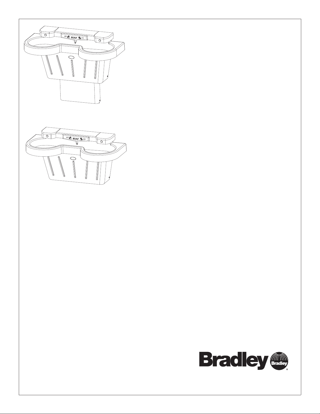
SS-2N/IR/STD
SS-2N/IR-WH
SS-2N/IR/STD/LSD-2
SS-2N/IR-WH/LSD-2
Express® Lavatory System SS-Series
Express Lavatory Systems are ADA and TAS compliant
U.S. Pat. Nos. 5,611,093, D447,224
Other Patents Pending
Table of Contents
Pre-Installation Information .........................2
Components .......................................3
Supplies Required .................................4
Dimensions..................................... 4–5
Rough-Ins .........................................6
Installation .................................... 7–10
Sensor Assembly and Solenoid Valve Access ........11
Solenoid Valve Troubleshooting .....................12
Navigator
Stop Valve Troubleshooting ........................14
Cleaning and Maintenance for Terreon
Soap Dispenser Maintenance ......................15
®
Mixing Valve Troubleshooting ............13
®
.............14
215-1497 Rev. G; ECM 11-08-011
© 2011 Bradley Corporation
Page 1 of 15 10/19/11
P.O. Box 309, Menomonee Falls, WI USA 53052-0309
PHONE 800.BRADLEY (800.272.3539) FAX 262.251.5817
bradleycorp.com
Page 2
SS-2N/IR/STD, SS-2N/IR/WH Installation
IMPORTANT!
Installation
Read this entire installation manual to ensure proper installation. When fi nished with the
installation, fi le this manual with the owner or maintenance department. Compliance and
conformity to local codes and ordinances is the responsibility of the installer.
Separate parts from packaging and make sure all parts are accounted for before discarding any
Packing List
•
•
packaging material. If any parts are missing, do not begin installation until you obtain the missing
•
S
I
H
T
E
ID
S
P
•
U
parts.
Make sure that all water supply lines have been fl ushed and then completely turned off before
beginning installation. Debris in supply lines can cause valves to malfunction.
Turn OFF electrical power to the electrical outlets, then unplug all electrical units prior to
installation. Electrical power MUST remain off until unit and optional water heater have been
plumbed. After installation is complete, turn on the water supply fi rst, then turn on the electrical
power.
Hardware supplied by installer must be appropriate for wall construction. Wall anchors must have
a minimum pull-out rating of 1,000 lbs. Follow appropriate dimensions for standard or juvenile
height based on confi guration and required rim height. Overtightening fasteners can damage the
Terreon® material. Use caution when tightening bowl and sprayhead fasteners.
Product warranties may be found in the “Products” section on our Web site at bradleycorp.com.
2 10/19/11 Bradley Corporation • 215-1497 Rev. G; ECM 11-08-011
Page 3
Installation SS-2N/IR/STD, SS-2N/IR/WH
Components
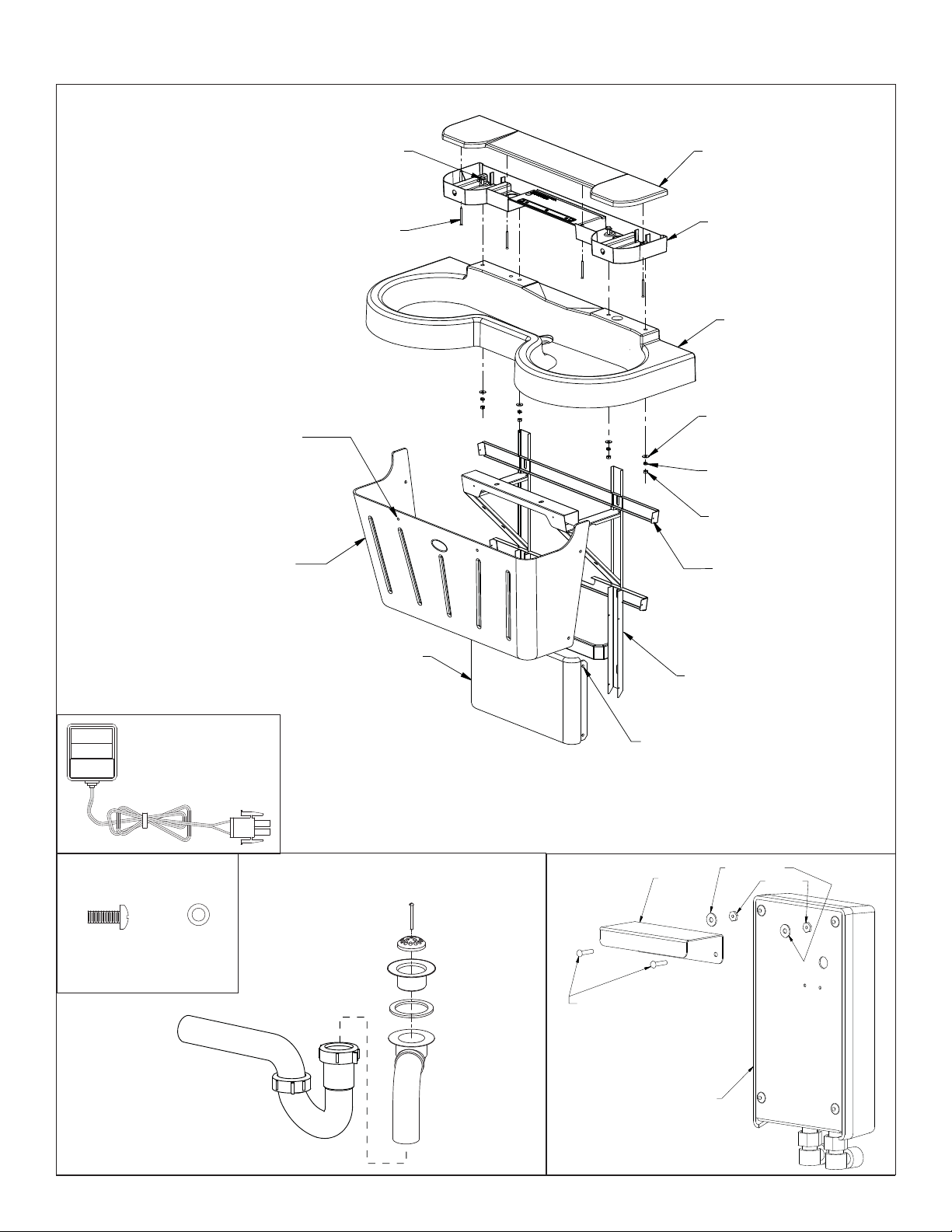
PA NE L
FASTENERS
(160-450)
WASHERS
(142-002CA)
(6) PLACES
ACCESS PANEL
GRAY (186-1455)
PUTTY (186-1455A)
COAL (186-1455B)
BOLT 5/16-18
160-371
SCREW 10-24
160-386
SPRAYHEAD COVER
(PART NUMBER VARIES WITH
COLOR OF UNIT. CONTACT
YOUR LOCAL BRADLEY REP.
FOR ASSISTANCE).
SPRAYHEAD BODY
(PART NUMBER VARIES WITH
COLOR OF UNIT. CONTACT
YOUR LOCAL BRADLEY REP.
FOR ASSISTANCE).
BOWL
(PART NUMBER VARIES
WITH COLOR OF UNIT.
CONTACT YOUR LOCAL
BRADLEY REP. FOR
ASSISTANCE).
WASHER
142-002BJ
LOCKWASHER
142-002BK
NUT 5/16-18
161-036
MAIN FRAME
S17-325
CLASS II PLUG-IN
TRANSFORMER
BOWL MOUNTING
HARDWARE
1/4"-20 x 1/2"
PAN HEAD
SCREW (qty. 2)
(160-389)
P-TRAP (POLYPROPYLENE)
(CHROME-PLATED BRASS)
(142-002DB)
(269-1697)
OPTIONAL P-TRAP
(S29-094)
110/24 VAC
S83-152
1/4"-20
WASHER
(qty. 2)
SCUFF BASE PANEL
GRAY (185-034)
PUTTY (185-034A)
COAL (185-034B)
DRAIN
ASSEMBLY
#8-32 SCREW
(160-319)
DRAIN PLUG
(P16-072)
STRAINER
(P16-075)
1/8" RUBBER
WASHER
(125-001DP)
TAILPIECE
(129-056)
SCUFF PANEL FASTENERS (160-450)
WASHERS (142-002CA)
(4) PLACES
#8-32 x 3/4"
ROUND HEAD
MACHINE SCREW
(160-276)
OPTIONAL WATER HEATER
EX95TMLB, 240/208 volts
EX100TMLB, 277 volts
SCUFF FRAME S17-326
USED WITH STANDARD
HEIGHT FRAME ONLY
BRACKET
(140-950)
(269-1767)
(269-1768)
#8 WASHER
#8 NUT
Bradley Corporation • 215-1497 Rev. G; ECM 11-08-011 10/19/11 3
Page 4
SS-2N/IR/STD, SS-2N/IR/WH Installation
Supplies Required:
• (6) ³⁄₈" wall anchors, bolts and 1" min. O.D. washers to mount main frame and bowl to wall (minimum pull-out rating of 1,000 lbs.)
• STD. HEIGHT ONLY: (2) ³⁄₈" wall anchors, bolts and 1" min. O.D. washers to mount scuff base to wall
• ½" nominal copper tubing for hot and cold supplies and 1½" NPT drain piping
• 110 volt GFCI protected electrical outlet for 1110/24 VAC plug-in transformer (supplied)
• OPTIONAL: 240/208-volt or 277-volt electrical box for electric tankless water heater
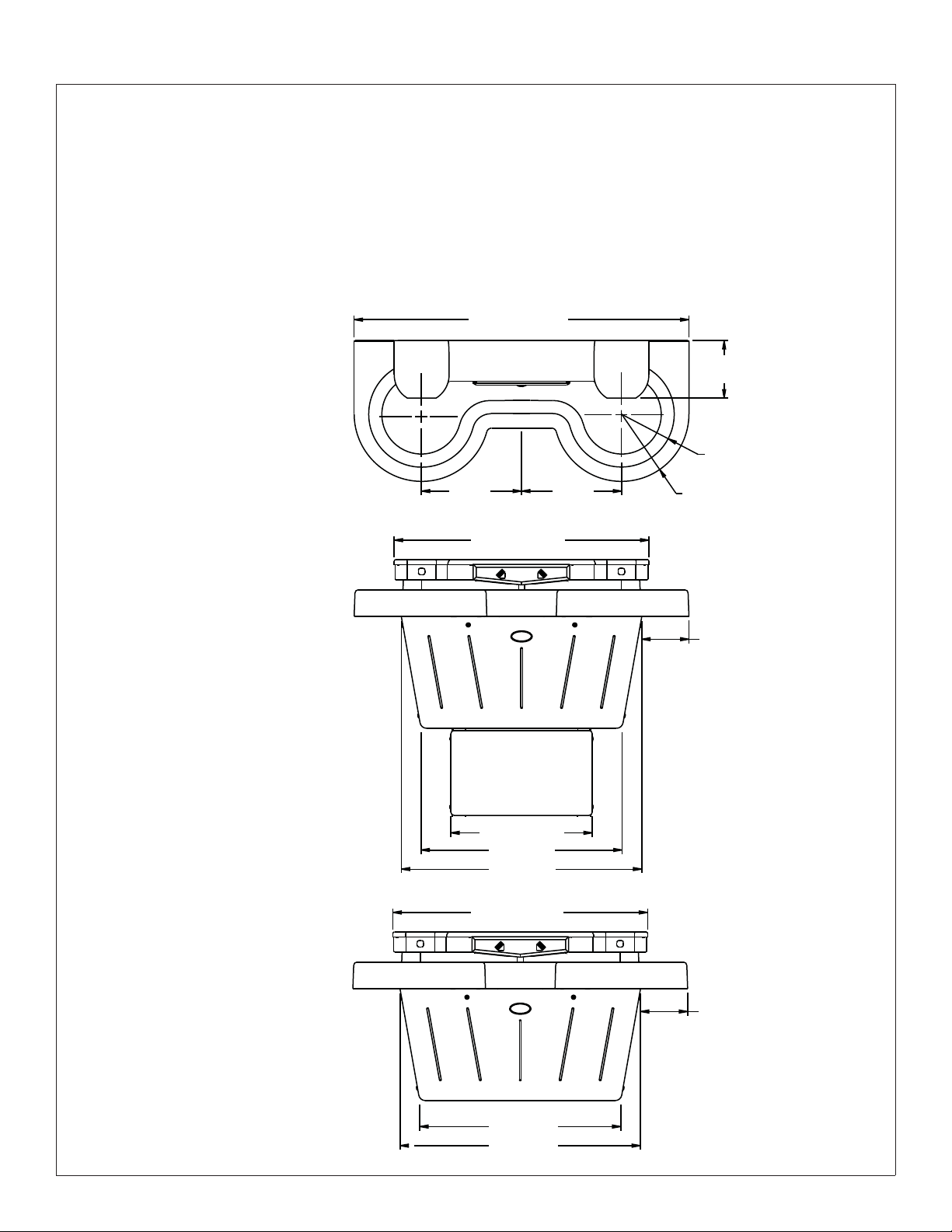
Dimensions - Front and Top Views
50" (1270mm)
Top View
85⁄8
" (219mm)
8" (203mm) Radius
Front View
Standard Frame
Front View
Wall-Hung Frame
15"
(381mm)
38¼" (972mm)
21¼" (540mm)
30" (762mm)
36" (914mm)
38¼" (972mm)
15"
(381mm)
10" (254mm) Radius
7" (178mm)
7" (178mm)
30" (762mm)
36" (914mm)
4 10/19/11 Bradley Corporation • 215-1497 Rev. G; ECM 11-08-011
Page 5
Installation SS-2N/IR/STD, SS-2N/IR/WH
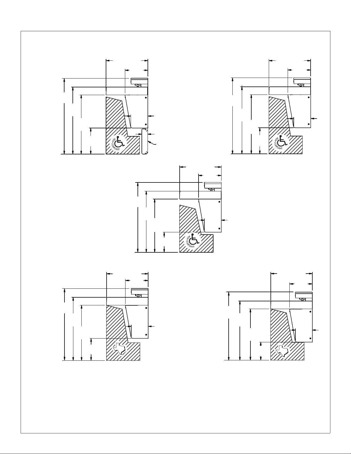
Dimensions - Side Views
Standard
Height
38½"
(978mm)
34"
(864mm)
30"
(762mm)
13¼"
(311mm)
Wall Hung Mounted
at Juvenile Height
Ages: 6 through 12
211⁄8" (537mm)
11½"
(292mm)
(219mm)
(902mm)
8
35½"
5
⁄8"
31"
(787mm)
3" (76mm)
Standard Height Only
27"
(686mm)
Scuff Base on
Wall Hung Mounted
at Standard Height
(978mm)
1
21
⁄8" (537mm)
11½"
(292mm)
5
⁄8"
8
(219mm)
38½"
34"
(864mm)
30"
(762mm)
13¼"
(311mm)
1
⁄8" (537mm)
21
11½"
(292mm)
8
(219mm)
5
⁄8"
Wall Hung Mounted
at TAS Height
Grades: 6
through
8 or 9
36½"
(927mm)
32"
(813mm)
(711mm)
28"
11¼"
(286mm)
211⁄8" (537mm)
11½"
(292mm)
(219mm)
TAS
85⁄8"
10¼"
(260mm)
Wall Hung Mounted
at TAS Height
Grades: Pre-K
through 5 or 6
34½"
(876mm)
30"
(762mm)
26"
(660mm)
9¼"
(235mm)
211⁄8" (537mm)
(292mm)
TAS
11½"
85⁄8"
(219mm)
Bradley Corporation • 215-1497 Rev. G; ECM 11-08-011 10/19/11 5
Page 6
SS-2N/IR/STD, SS-2N/IR/WH Installation
1
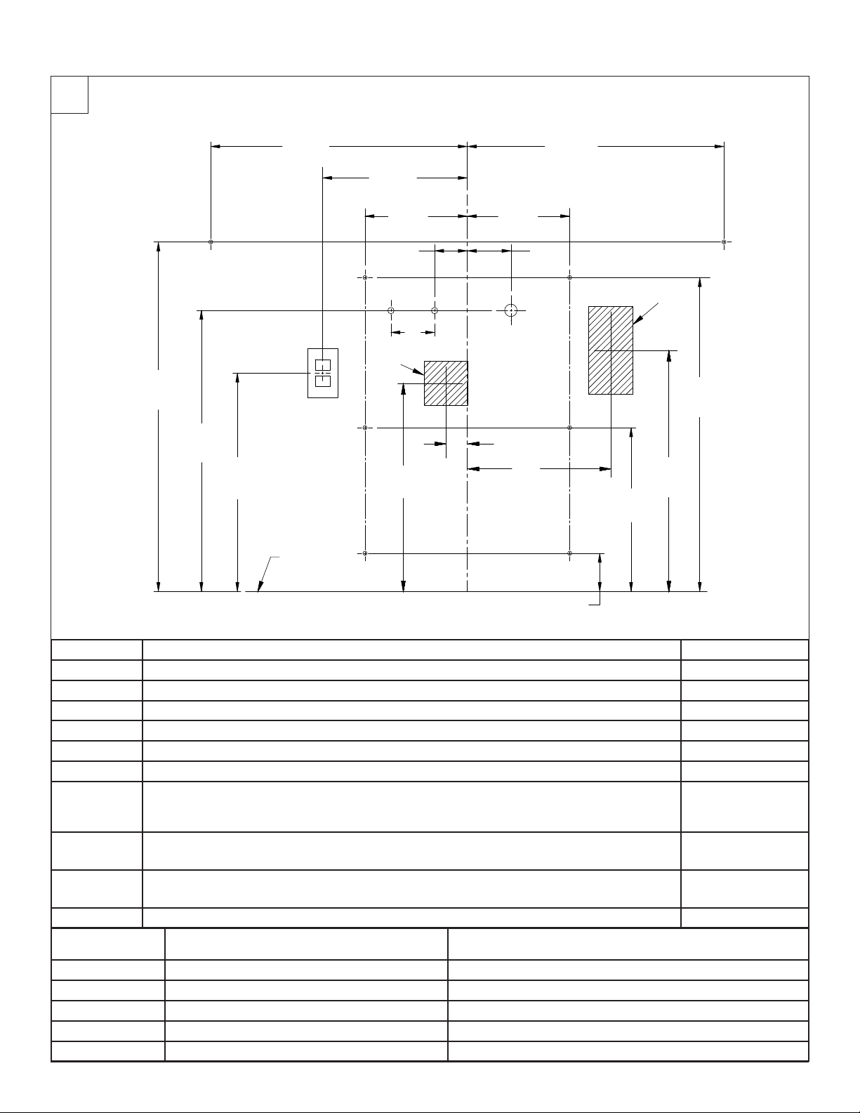
Rough-Ins
C
23-1/2"
(597mm)
13-1/4"
(337mm)
L
23-1/2"
(597mm)
32"
(813mm)
A
25-3/4"
(654mm)
20"
(508mm)
J
FLOOR
B
9-3/8"
(238mm)
(76mm)
D1
(102mm)
H
B
19"
(483mm)
C
3"
4"
D2
9-3/8"
(238mm)
4"
(102mm)
E
2" (51mm)
13"
(330mm)
B
B
C
3-1/2"
(89mm)
15"
(381mm)
G
(730mm)
22"
(559mm)
A
28-3/4"
CODE DESCRIPTION QTY.
A
B
C
D1 ½" nominal copper tubing for Cold Supply, stub-out 2" from wall 1
D2 ½" nominal copper tubing for Hot or Tempered Supply, stub-out 2" from wall 1
E 1½" NPT Drain, stub-out 2" from wall 2
F
G
H
J 110v GFI Protected Electrical Outlet 1
RIM HEIGHT
34" None Standard Height
34" None Wall-Hung
32" Subtract 2" TAS, Grades 6 through 8 or 9
31" Subtract 3" Juvenile Height
30" Subtract 4" TAS, Pre-K through Grades 5 or 6
³⁄₈" Wall Anchors with a minimum pull-out force of 1,000 lbs. for Bowl
³⁄₈" Wall Anchors with a minimum pull-out force of 1,000 lbs. for Mainframe
³⁄₈" Wall Anchors for Base Frame, Standard Frame option only, minimum pull-out force not required
On the bowl back, measure the distance between the ¾" bowl mounting holes. Divide this measurement
in half. Measure and mark this dimension on the wall to the left and the right of the centerline. Install two
³⁄₈" wall anchors with a minimum pull-out rating of 1,000 lbs (supplied by installer) at locations marked.
Water Heater Option #1: Rough-in appropriate electrical supply per local code (recommended location for
240/208v or 277v electrical box [4" long x 4" wide x 8" high] shown)
Water Heater Option #2: Rough-in appropriate electrical supply per local code (recommended location for
240/208v or 277v electrical box [4" long x 4" wide x 4" high] shown)
VERTICAL HEIGHT ADJUSTMENTS FOR CODES
A–E, H, C and W
FIXTURE STYLE
2
4
2
2
1
1
6 10/19/11 Bradley Corporation • 215-1497 Rev. G; ECM 11-08-011
Page 7
Installation SS-2N/IR/STD, SS-2N/IR/WH
2
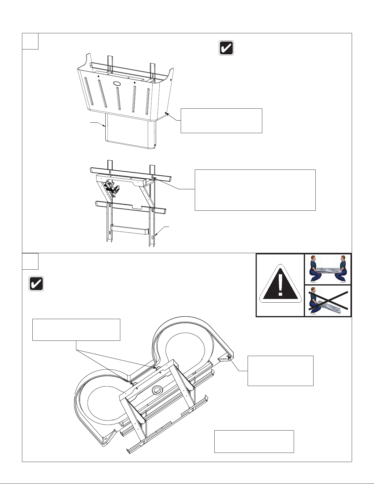
Mount Frame to Wall
SCUFF PANEL
STANDARD HEIGHT
FRAME ONLY
Using a T20 torx key, remove
the fasteners securing the
A
access panel to the main
frame, and remove the panel.
Once you have positioned the frame such that
it is level and flat against the wall or shimmed ,
mount the frame to the wall at four places using
³⁄₈" bolts and 1” min. O.D. washers.
B
NOTE: When mounting the standard height frame,
mount the scuff base to the wall at the same time
using two additional ³⁄₈" bolts and washers.
Anchoring the frame to a wall that is not
flat may cause the frame to bend, making
it difficult to reinstall the access panels. If
necessary, use shims to compensate for
wall distortion.
3
Install Bowl
A
SCUFF BASE FRAME
STANDARD HEIGHT
FRAME ONLY
The sprayhead body has slotted holes for adjusting the fit-up with the bowl and wall.
The tailpiece on the waste tee has been rotated upward for shipping purposes. Turn
the tailpiece down to its proper position before installing the bowl.
Attach the bowl to the frame with
¼"-20 x ½" pan-head screws and
washers. Do not tighten.
Secure the bowl to the
wall anchors with ³⁄₈"
bolts and 1" min. O.D.
B
washers, two places.
Do not overtighten.
Tighten the pan-head screws
Do not overtighten.
C
Bradley Corporation • 215-1497 Rev. G; ECM 11-08-011 10/19/11 7
Page 8
SS-2N/IR/STD, SS-2N/IR/WH Installation
4a
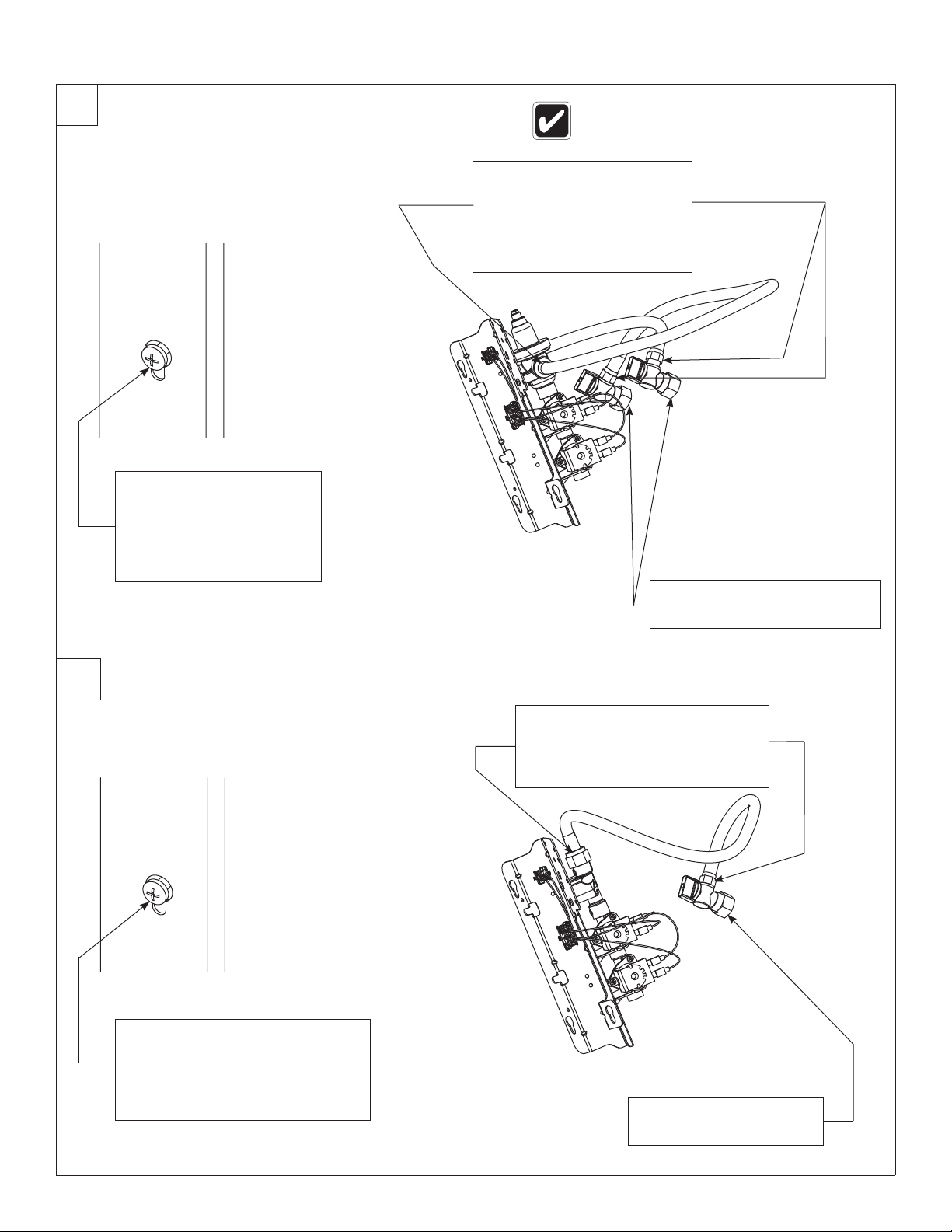
Connect the Supply — Hot and Cold Supply
C
Loosen but do not remove
the two mounting screws
holding the valve bracket
to the frame.
A
Slide the valve bracket up
and lift it from the frame.
Connect one end of each
hose to the Navigator valve
(one on the hot side, one on
the cold side).
Connect the other swivel
end to the stop valves.
The letter “H” on the Navigator Mixing
Valve indicates hot water supply inlet.
4b
Connect the Supply — Single Tempered Supply
Loosen but do not remove the two
mounting screws holding the valve
bracket to the frame.
A
Slide the valve bracket up and lift
it from the frame.
B
Connect one end of flexible hose
to the tempered line adapter.
C
Connect the other swivel end to
the stop valve.
Attach the stop to the
tempered wall stub-out.
B
Attach the stops to the hot
and cold water wall stub-outs.
8 10/19/11 Bradley Corporation • 215-1497 Rev. G; ECM 11-08-011
Page 9
Installation SS-2N/IR/STD, SS-2N/IR/WH
5
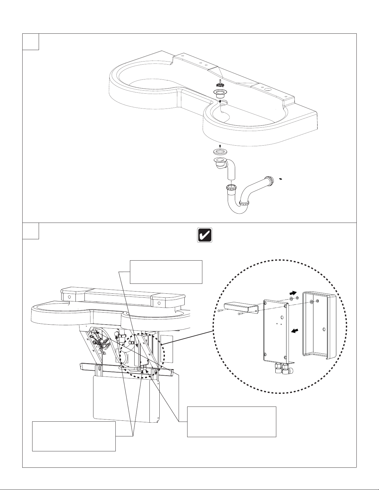
Install the Drain
To Drain
Stub-Out
6
Optional Electric Tankless Water Heater
A
240/208 or 277 voltage is required for hot water heater.
Refer to the installation manual provided with the hot
water heater for further installation information.
Hang the water heater
on the right side frame
member.
Connect the ½" flexible hose
from the hot water heater
outlet to the supply inlet on
Connect the ½" flexible
hose from the cold water
supply stub-out to the hot
B
water heater inlet.
Bradley Corporation • 215-1497 Rev. G; ECM 11-08-011 10/19/11 9
C
the solenoid valve assembly.
Page 10
SS-2N/IR/STD, SS-2N/IR/WH Installation
7
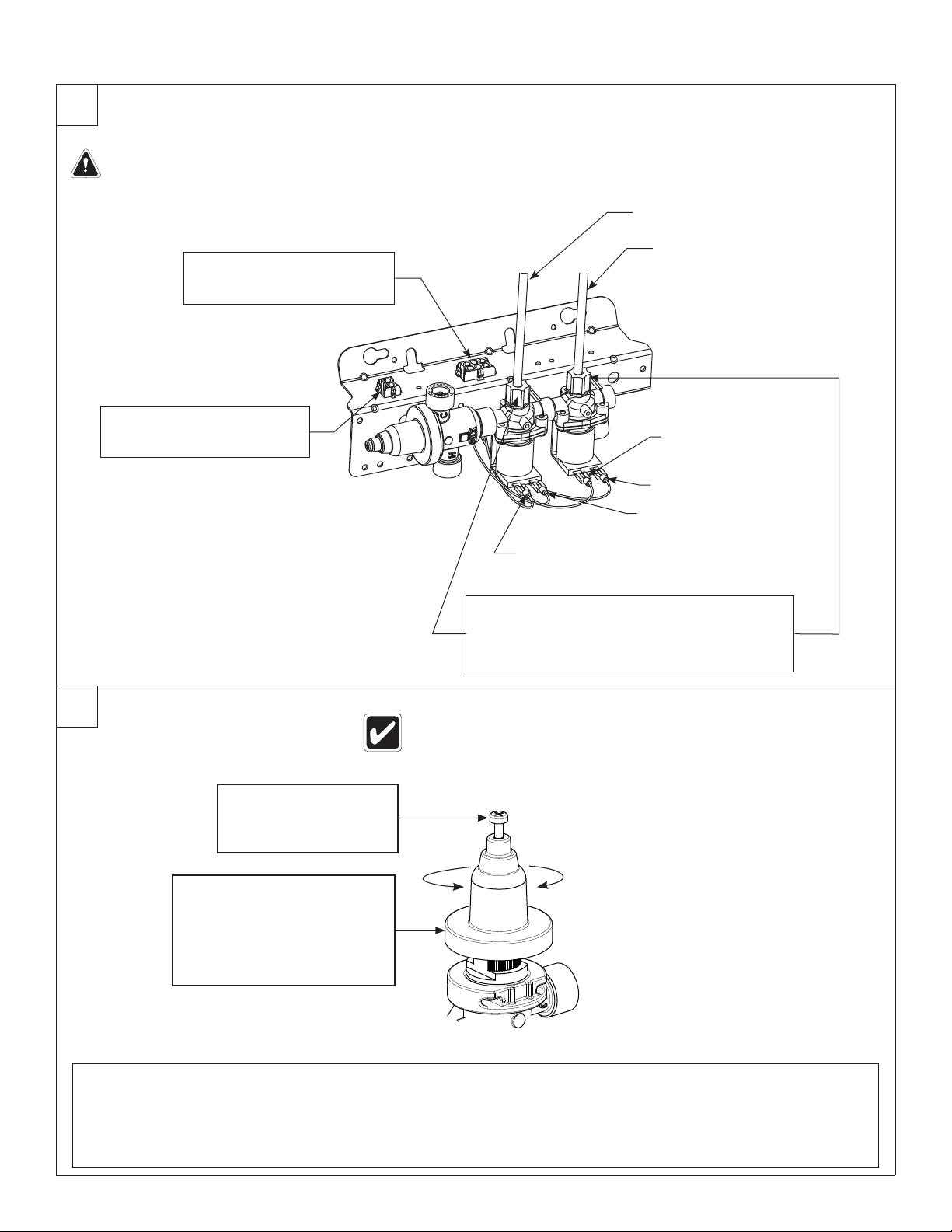
Connect Electrical and Sprayhead Supplies
WARNING: The Express® control must be connected with the 24 VAC Class II transformer provided. Connections
to 110 VAC can cause personal injury and will result in damage to the electronics. Connection of leads other than
shown may cause permanent damage to the sensor.
Green Supply Tube
(from Sprayhead)
Red Supply Tube
(from Sprayhead)
White Spade Terminal
Red Spade Terminal
A
Snap the transformer's
circuit plug into the female
B
transformer circuit plug.
Connect the sensor circuit
plug from the sprayhead to
the solenoid circuit plug.
8
Adjust the Temperature
Using the cover, turn the
cartridge gently until
desired water temperature
is reached. Do not turn past
B
stops as this may damage
the unit. Push the cover
down and tighten the screw.
Loosen the cap screw
about ¼" (4–6 turns)
and lift up the cover
A
(do not remove).
Green Spade Terminal
White Spade Terminal
Loosen the compression nuts.
Push the sprayhead supply tubes firmly into
the tube connectors until they are fully seated.
C
Tighten the compression nuts by hand.
This valve is NOT factory preset. Upon installation, the temperature of this
valve must be checked and adjusted to ensure delivery of a safe water
temperature. Water in excess of 110°F (43°C) may cause scalding.
H
C
Reinstall the valve bracket. Turn on the water supply and check for leaks. Turn on the electrical power to the electrical outlet
and pass your hand in front of each station’s sensor until all the air is purged from the lines and water is flowing smoothly.
Reinstall the access panel.
C
START-UP NOTE: Wait two full minutes after making the power connection before using the lav. The sensors will take up to
eight full minutes (while not in use) to adapt to the bowl if another object is detected during the two-minute start-up period.
10 10/19/11 Bradley Corporation • 215-1497 Rev. G; ECM 11-08-011
Page 11
Installation SS-2N/IR/STD, SS-2N/IR/WH
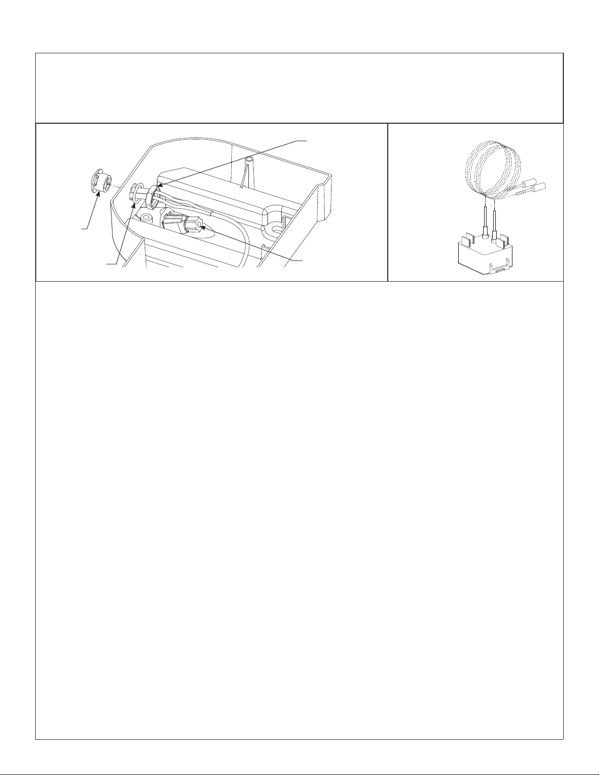
Sensor assembly and solenoid valve access
• To access sensors: Remove the Phillips-head screws located in the bottom of the sprayhead body and lift the Terreon
cover/shelf off.
• To reinstall sprayhead cover/shelf: Position the cover/shelf on the sprayhead body and secure it to the sprayhead body
using the screws provided.
Sprayhead
Components
Window
(269-1241)
O-Ring
(125-157)
Nut, ½"-14 NSPM
(110-115)
Aerator Assembly
(S05-180)
INFRARED SENSOR
269-1608HP
Bradley Corporation • 215-1497 Rev. G; ECM 11-08-011 10/19/11 11
Page 12
SS-2N/IR/STD, SS-2N/IR/WH Installation
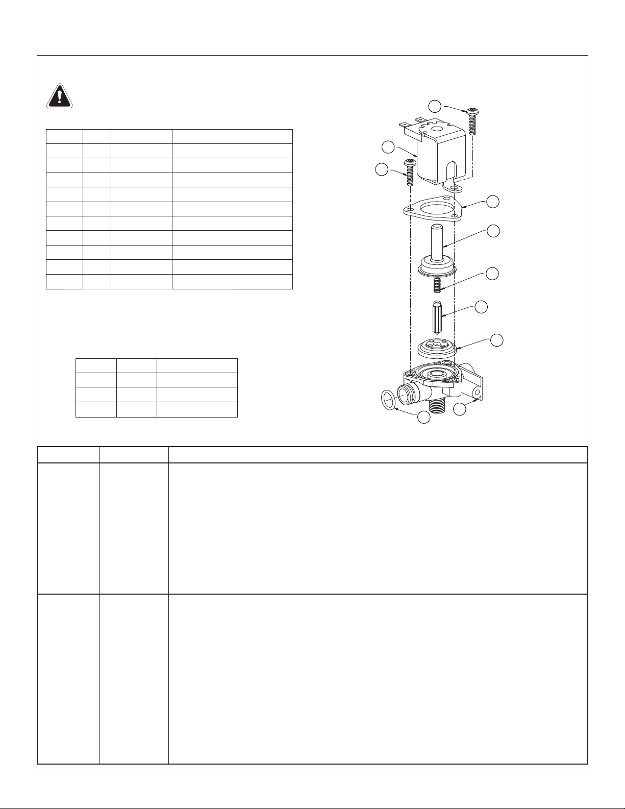
Troubleshooting – Solenoid Valve: Part nos. S07-067 (closed body) & S07-067A (thru body)
Turn off water supplies to the unit before troubleshooting.
Item Qty. Part No. Description
1 1 118-307 Valve Body, ¼" Closed
1 1 118-307A Valve Body, ¼" Thru
2 1 269-983 Diaphram
3 1 269-577 Armature
4 1 269-578 Spring
5 1 269-1729 Armature Housing
6 1 269-1730 Clamp, Armature Housing
7 1 269-579 Coil, Solenoid Valve
8 3 160-447 Screw, #8 x 5/8
9 1 125-165 O-Ring, #2-013
Repair Kit S65-113
Item Qty. Description
2 1 Diaphram
3 1 Armature
4 1 Spring
8
7
8
6
5
4
3
2
9
1
Problem Cause Solution
An individual
operating
station fails to
shut off and
drips.
An individual
operating
station fails to
turn on.
Debris is
trapped
between the
diaphragm
and the
valve seat.
A failed coil for
the valve or
loose electrical
connection to
the terminal.
Remove debris between diaphragm and the valve seat.
1. Remove the three #8 Phillips-head screws that hold the solenoid valve assembly together. Be careful not
to lose the armature or spring.
2. Remove the diaphragm. Remove any particles that have been trapped between the diaphragm and the
valve seat. Rinse off the diaphragm and inspect for damage. Make sure the center orifi ce and both small
side orifi ces are open.
3. Reassemble in reverse order (do not overtighten the Phillips-head screws or the plastic valve body may
crack). Tighten until the armature plate makes contact with the plastic body.
4. Reconnect the wiring.
Test the station to determine the cause.
1. Disconnect the wires from the coil of an adjacent valve. Disconnect the wires from the problem valve and
reconnect to the adjacent valve.
2. Turn on electrical and water supplies to the unit. Pass your hand in front of the sensor of the problem
station, and the adjacent station should turn on.
If the adjacent station turns on and cycles normally, replace the coil on the problem valve.
If the adjacent valve fails to turn on, inspect the wires from the sensor cable and do the following:
• make sure there are no breaks and that the fully insulated disconnect terminals are fi rmly crimped in place;
• turn off the electrical and water supplies;
• reconnect to the adjacent valve and turn on the water supplies to the unit;
• pass your hand in front of the sensor. If the station still fails to turn on, replace the sensor.
12 10/19/11 Bradley Corporation • 215-1497 Rev. G; ECM 11-08-011
Page 13
Installation SS-2N/IR/STD, SS-2N/IR/WH
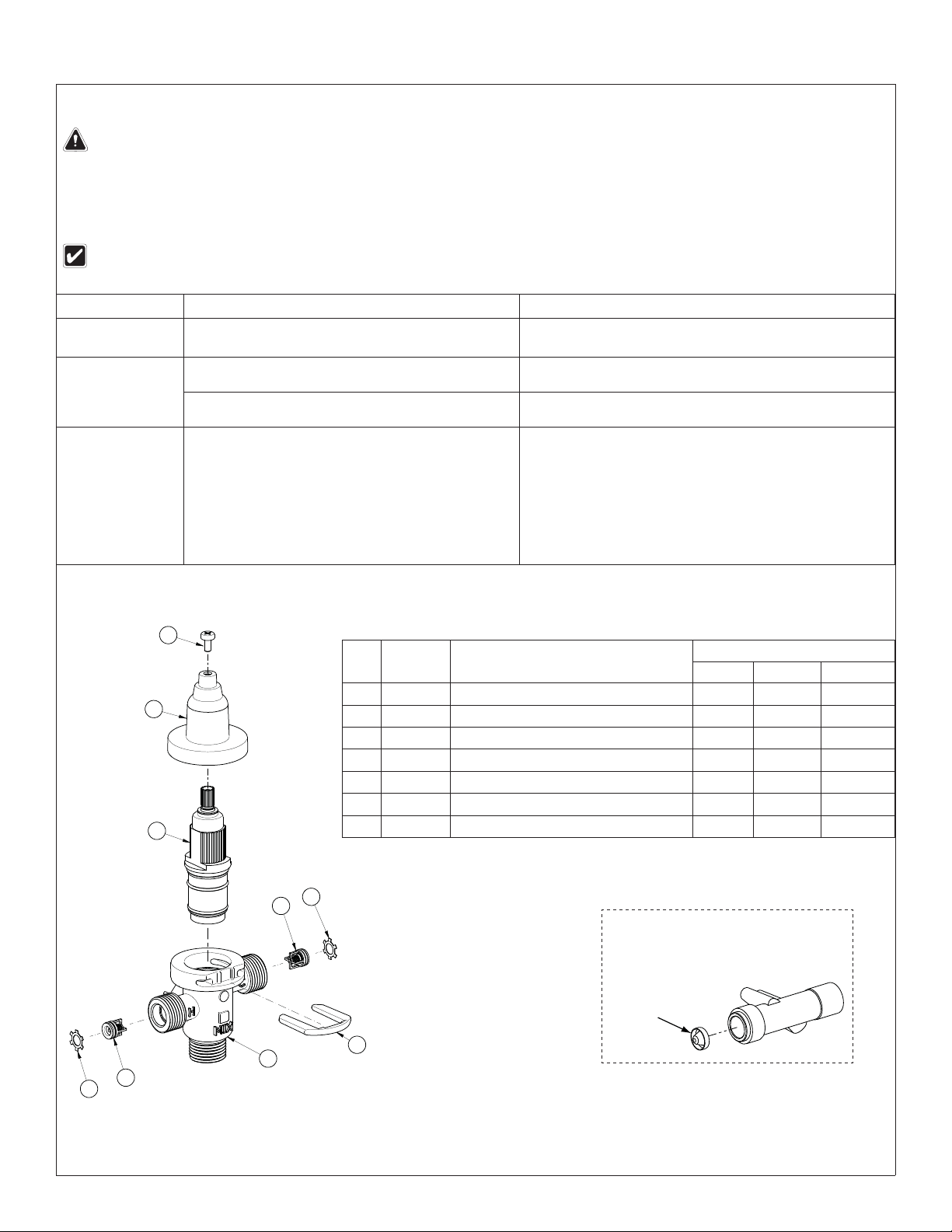
Thermostatic Mixing Valve Troubleshooting
Before attempting to troubleshoot the valve or disassemble the components, check for the following conditions:
• If stop valves are used, make sure that they are fully open.
• Make sure that the hot and cold inlet pipes are connected properly, and that there are no cross-connections or
leaking stop valves.
• Check the hot water heater output to make sure that it is at least 10° F above the set temperature.
Be sure to close the appropriate shut-off valves prior to disassembly of the valve and reopen the valves after inspection and
repair is complete.
Problem Cause Solution
External
leaks.
Improper water
temperature or
temperature
fluctuation.
Limited water
flow.
Damaged cartridge or O-rings. Replace cartridge with part number 269-1927
Hot water supply is not 10° above desired set point. Increase hot water supply temperature
Valve temperature is not properly set. Adjust the temperature as shown on page 10, step 8.
Dirt and debris have built up in the valve or strainer. 1. Check to make sure both hot and cold supplies are
connected to the Navigator mixing valve and that they
have water flow.
2. Remove cover and U-clip. Remove the cartridge and
clean the strainer. It is not required to grease cartridge,
however if desired, use silicone grease only. Do not use
grease on check valves.
1
2
3
4
Parts List
Item Part No. Description
1 160-463 Cap Screw 1 1 1
2 107-582 Cover 1 1 1
3 269-1927 Thermostatic Cartridge 1 1 1
4 198-014 Check Valve* 2 2 2
5 132-051 Retaining Ring* 2 2 2
6 118-319 Valve Body 1 1 1
7 146-079 U-Clip 1 1 1
* Included with Prepack S65-326
5
Quantity
S59-4000 S59-4000A S59-4000BY
Tempered Line Adapter Option
Part no. S39-804
(replaces S59-4000 if tempered line
is used)
Strainer
6
4
5
7
(173-028)
Bradley Corporation • 215-1497 Rev. G; ECM 11-08-011 10/19/11 13
Page 14
SS-2N/IR/STD, SS-2N/IR/WH Installation
Stop Valve Troubleshooting
Problem Cause Solution
Water dribbles or
does not fl ow from the
sprayhead.
Stop Valves may
not be functioning
properly.
1. Close the stops and inspect the valves that supply water to the lavatory
system.
2. Inspect the stop valves to see that they have been properly installed.
Sprayhead delivers
ONLY hot OR cold water.
Stop Valves may
not be functioning
1. Close the stops and inspect the valves that supply water to the lavatory
system.
properly.
2. Inspect the stop valves to see that they have been properly installed.
3. Inspect the thermostatic mixing valve for proper installation and
connection to hot and cold supplies.
Cleaning and Maintenance for Terreon
®
Material Description: Terreon is an NAHB-certifi ed densifi ed solid surface material composed of polyester resin and is resistant to
chemicals, stains, burns and impact. Surface damage can be easily repaired with everyday cleansers or fi ne grit abrasives.
Routine Cleaning: Clean daily or as often as conditions require using a standard commercial or household cleaner such as
Formula 409
Stubborn Stains: Remove tough stains with Ajax
®
or Windex®.
®
, Comet®, or Soft-Scrub® and a green Scotch-Brite® pad or lightly sand in a
circular motion with 240 grit wet/dry sandpaper. The fi nish can be renewed with a maroon Scotch-Brite pad.
Special Situations for Terreon Material
Scratches: Remove scratches with a green Scotch-Brite pad. The fi nish can then be renewed with a maroon Scotch-Brite
pad, followed by a white Scotch-Brite pad or 30-micron sandpaper.
Hard Water Deposits: Remove hard water deposits with a mild solution of vinegar and water. Always rinse the unit thoroughly
after cleaning.
Restoring the surface: Use Hope’s
material. Bradley recommends additional care and maintenance for the darker colored Terreon. For complete instructions on
this additional maintenance, visit bradleycorp.com.
®
Solid Surface cleaner and polish to refresh and protect the Terreon Solid Surface
Do not use strong acid or alkaline chemicals and cleansers to clean Terreon. If these chemicals come in contact
with the surface, wipe them off immediately and rinse with soapy water. Avoid contact with harsh chemicals such
as paint remover, bleach, acetone, etc. Avoid contact with hot pans and objects.
Repair Kits: Terreon repair kits are available. Contact your Bradley representative or distributor for part numbers and pricing.
Repair kits are made to order and have a shelf life of 30 days.
Terreon® is a unique, cast solid surface material. Aggregate fl ow and distribution as well as shades of color can vary from
product to product creating natural characteristics.
Brand Names
Use of brand names is intended only to indicate a type of cleaner. This does not constitute an endorsement, nor does the omission
of any brand name cleaner imply inadequacy. Many products named are regional in distribution, and can be found in local
supermarkets, department and hardware stores, or through your cleaning service. It is emphasized that all products should be used
in strict accordance with package instructions.
14 10/19/11 Bradley Corporation • 215-1497 Rev. G; ECM 11-08-011
Page 15
Installation SS-2N/IR/STD, SS-2N/IR/WH
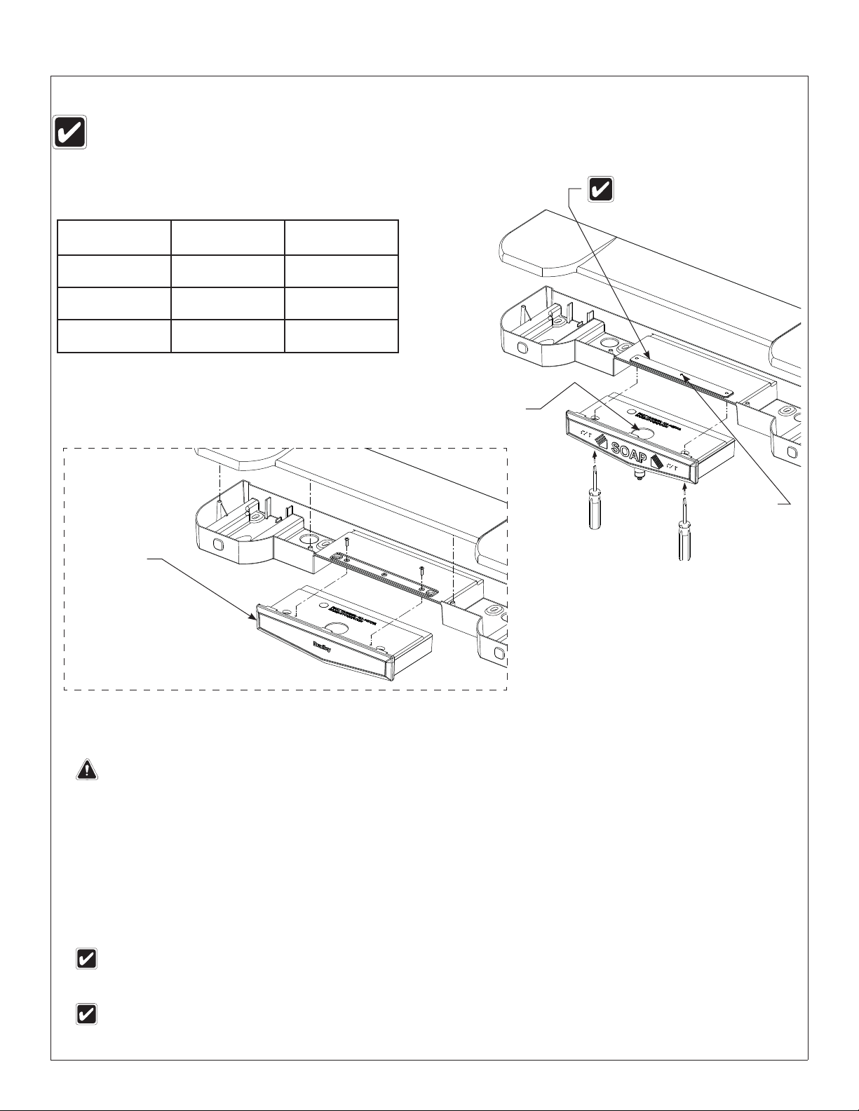
Fill Soap Dispenser
The soap valve will dispense vegetable/coconut oil liquid soaps, synthetic detergents, viscous lotion soaps, and antiseptic solutions.
A 10-15% con cen tra tion is rec om mend ed for veg e ta ble or co co nut oil liquid soaps. Before filling, rinse out each soap tank with
hot water to remove packing dust. Shake water out thor ough ly and allow to dry. DO NOT OVERFILL!
Leaf Spring will engage when
Soap Tank Kits
soap tank is pushed into place.
S65-291 (Gray)
includes:
Gray Tank w/Valve
(S11-220)
Leaf Spring
(S39-350)
Screw
(160-385)
S65-291A (Putty)
includes:
Putty Tank w/Valve
(S11-220A)
Leaf Spring
(S39-350)
Screw
(160-385)
S65-291B (Coal)
includes:
Coal Tank w/Valve
(S11-220B)
Leaf Spring
(S39-350)
(160-385)
Soap Valve Repair Kit (S65-258)
(includes Nut, Spring, Washer and Plunger)
Soap Blank
Gray (133-143)
Putty (133-143A)
Coal (133-143B)
Screw
Filler
Hole
#10 Screw
Clean Soap Dispenser
Do not use abrasive cleansers to clean the soap tank. Abrasive cleaners can damage the surface.
Regular cleaning of the soap dispenser is recommended to ensure optimum performance and maximum service life. Cleaning the
soap dispenser monthly to remove soap residue, dirt, and other accumulations should become a regular part of your washroom
cleaning routine and general maintenance program.
Clean exterior: Use warm water and soap to clean the exterior of the soap dispenser. Dry with a soft cloth.
Clean interior: Inspect the interior of the tank for residue or coagulation of soap. If necessary, clean the tank according to the
following procedure:
1. Pour out any remaining soap in the tank.
2. Full the tank half-full of hot water and shake the tank to dislodge the soap residue.
3. Empty the water from the container and repeat steps 1 and 2 until the soap container is clean.
If rinsing alone does not remove the soap residue, place a small chain (24 inches long) into the tank with hot water and
shake the container until the chain dislodges the residue. Then remove the chain and rinse out the tank.
Clean internal components: Pump hot water through the soap dispenser until a clean flow of water comes out of the valve.
To change soap, pour out all of the soap from the dispenser ans rinse with hot water several times until all residue is
removed. Pump the valve until clean water appears. Rinse the dispenser with ethyl alcohol; air dry before refilling.
Bradley Corporation • 215-1497 Rev. G; ECM 11-08-011 10/19/11 15
 Loading...