

Bradley Express SS Series, Express SS-2N, Express SS-IR, Express SS-STD, Express SS-2N-WH Installation Manual
...
Installation
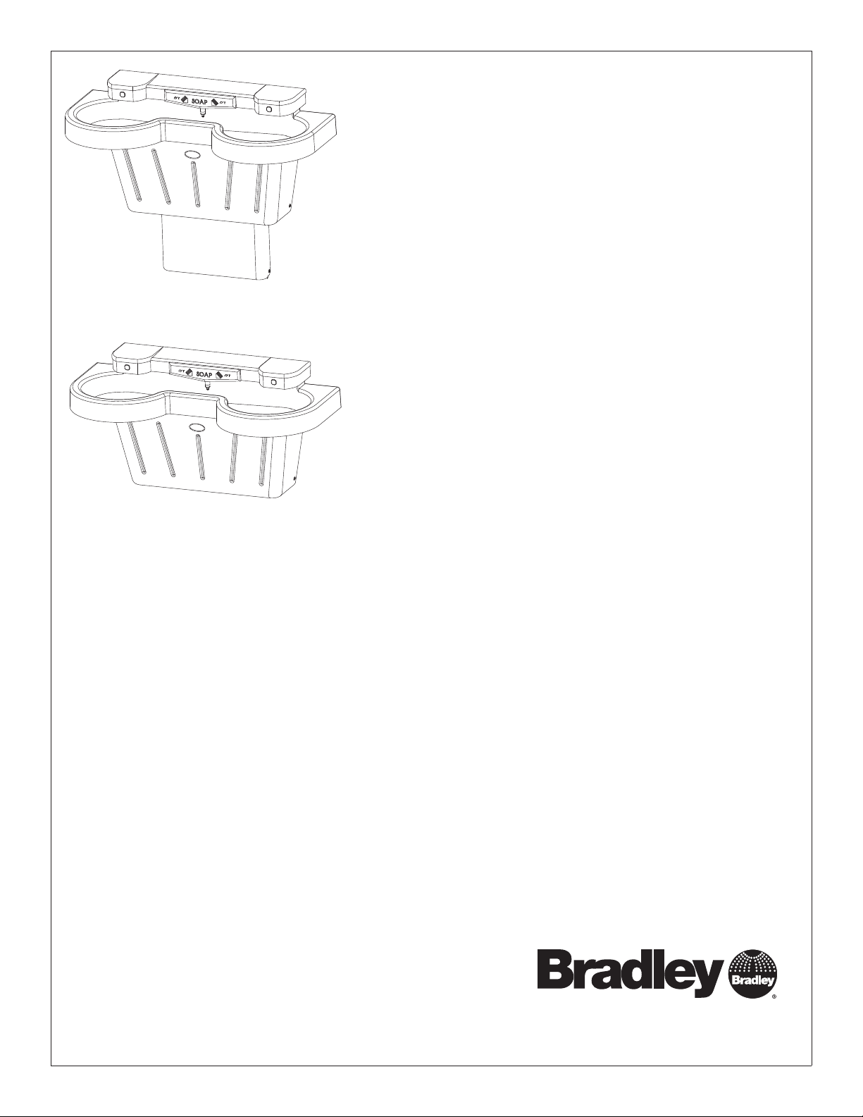
SS-2N/IR/STD
SS-2N/IR-WH
SS-2N/IR/STD/LSD-2
SS-2N/IR-WH/LSD-2
Express® Lavatory System SS-Series
Express Lavatory Systems are ADA and TAS compliant
U.S. Pat. Nos. 5,611,093, D447,224
Other Patents Pending
Table of Contents
Pre-Installation Information .........................2
Components .......................................3
Supplies Required .................................4
Dimensions..................................... 4–5
Rough-Ins .........................................6
Installation .................................... 7–10
Sensor Assembly and Solenoid Valve Access ........11
Solenoid Valve Troubleshooting .....................12
Navigator
Stop Valve Troubleshooting ........................14
Cleaning and Maintenance for Terreon
Soap Dispenser Maintenance ......................15
®
Mixing Valve Troubleshooting ............13
®
.............14
215-1497 Rev. G; ECM 11-08-011
© 2011 Bradley Corporation
Page 1 of 15 10/19/11
P.O. Box 309, Menomonee Falls, WI USA 53052-0309
PHONE 800.BRADLEY (800.272.3539) FAX 262.251.5817
bradleycorp.com
SS-2N/IR/STD, SS-2N/IR/WH Installation
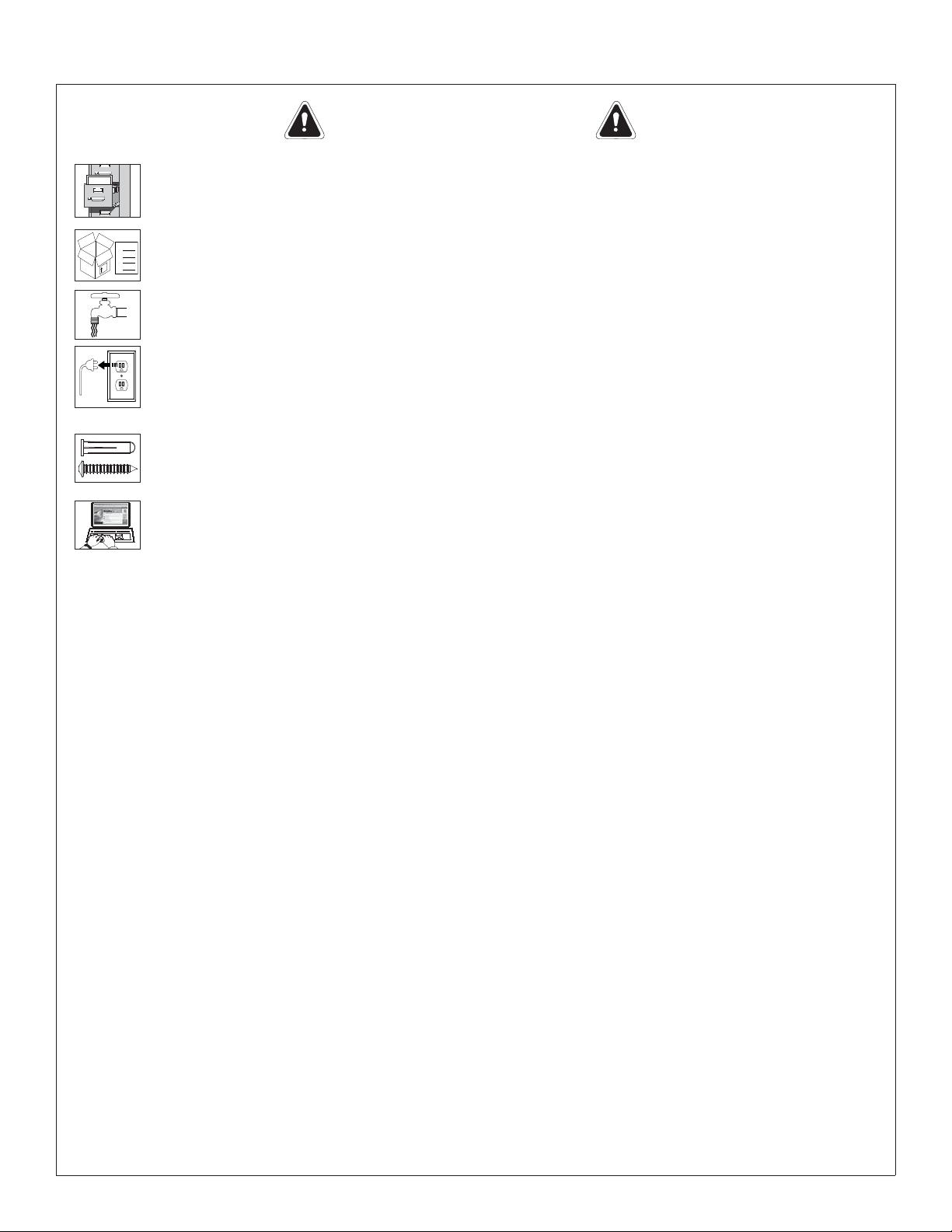
IMPORTANT!
Installation
Read this entire installation manual to ensure proper installation. When fi nished with the
installation, fi le this manual with the owner or maintenance department. Compliance and
conformity to local codes and ordinances is the responsibility of the installer.
Separate parts from packaging and make sure all parts are accounted for before discarding any
Packing List
•
•
packaging material. If any parts are missing, do not begin installation until you obtain the missing
•
S
I
H
T
E
ID
S
P
•
U
parts.
Make sure that all water supply lines have been fl ushed and then completely turned off before
beginning installation. Debris in supply lines can cause valves to malfunction.
Turn OFF electrical power to the electrical outlets, then unplug all electrical units prior to
installation. Electrical power MUST remain off until unit and optional water heater have been
plumbed. After installation is complete, turn on the water supply fi rst, then turn on the electrical
power.
Hardware supplied by installer must be appropriate for wall construction. Wall anchors must have
a minimum pull-out rating of 1,000 lbs. Follow appropriate dimensions for standard or juvenile
height based on confi guration and required rim height. Overtightening fasteners can damage the
Terreon® material. Use caution when tightening bowl and sprayhead fasteners.
Product warranties may be found in the “Products” section on our Web site at bradleycorp.com.
2 10/19/11 Bradley Corporation • 215-1497 Rev. G; ECM 11-08-011
Installation SS-2N/IR/STD, SS-2N/IR/WH
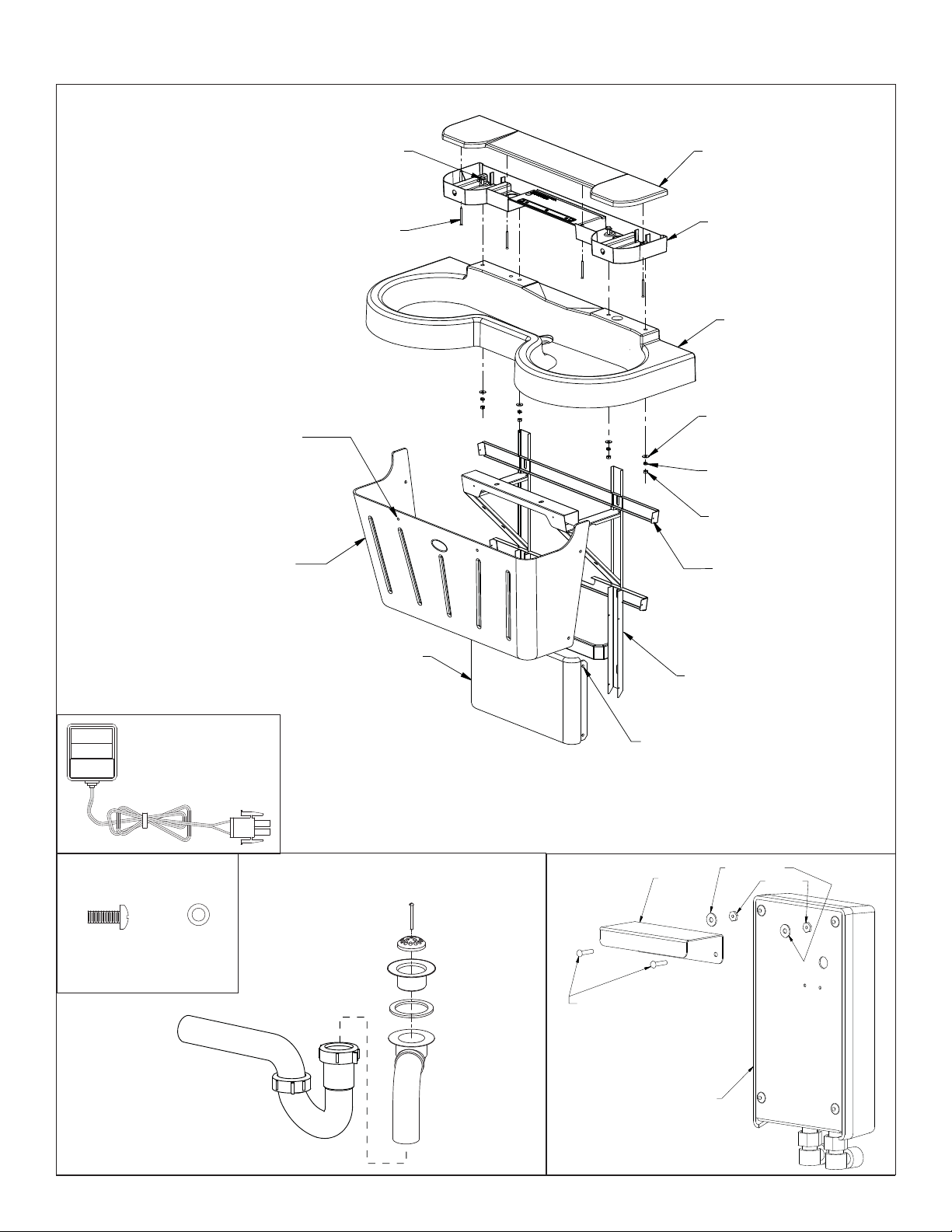
Components
PA NE L
FASTENERS
(160-450)
WASHERS
(142-002CA)
(6) PLACES
ACCESS PANEL
GRAY (186-1455)
PUTTY (186-1455A)
COAL (186-1455B)
BOLT 5/16-18
160-371
SCREW 10-24
160-386
SPRAYHEAD COVER
(PART NUMBER VARIES WITH
COLOR OF UNIT. CONTACT
YOUR LOCAL BRADLEY REP.
FOR ASSISTANCE).
SPRAYHEAD BODY
(PART NUMBER VARIES WITH
COLOR OF UNIT. CONTACT
YOUR LOCAL BRADLEY REP.
FOR ASSISTANCE).
BOWL
(PART NUMBER VARIES
WITH COLOR OF UNIT.
CONTACT YOUR LOCAL
BRADLEY REP. FOR
ASSISTANCE).
WASHER
142-002BJ
LOCKWASHER
142-002BK
NUT 5/16-18
161-036
MAIN FRAME
S17-325
CLASS II PLUG-IN
TRANSFORMER
BOWL MOUNTING
HARDWARE
1/4"-20 x 1/2"
PAN HEAD
SCREW (qty. 2)
(160-389)
P-TRAP (POLYPROPYLENE)
(CHROME-PLATED BRASS)
(142-002DB)
(269-1697)
OPTIONAL P-TRAP
(S29-094)
110/24 VAC
S83-152
1/4"-20
WASHER
(qty. 2)
SCUFF BASE PANEL
GRAY (185-034)
PUTTY (185-034A)
COAL (185-034B)
DRAIN
ASSEMBLY
#8-32 SCREW
(160-319)
DRAIN PLUG
(P16-072)
STRAINER
(P16-075)
1/8" RUBBER
WASHER
(125-001DP)
TAILPIECE
(129-056)
SCUFF PANEL FASTENERS (160-450)
WASHERS (142-002CA)
(4) PLACES
#8-32 x 3/4"
ROUND HEAD
MACHINE SCREW
(160-276)
OPTIONAL WATER HEATER
EX95TMLB, 240/208 volts
EX100TMLB, 277 volts
SCUFF FRAME S17-326
USED WITH STANDARD
HEIGHT FRAME ONLY
BRACKET
(140-950)
(269-1767)
(269-1768)
#8 WASHER
#8 NUT
Bradley Corporation • 215-1497 Rev. G; ECM 11-08-011 10/19/11 3
SS-2N/IR/STD, SS-2N/IR/WH Installation
Supplies Required:
• (6) ³⁄₈" wall anchors, bolts and 1" min. O.D. washers to mount main frame and bowl to wall (minimum pull-out rating of 1,000 lbs.)
• STD. HEIGHT ONLY: (2) ³⁄₈" wall anchors, bolts and 1" min. O.D. washers to mount scuff base to wall
• ½" nominal copper tubing for hot and cold supplies and 1½" NPT drain piping
• 110 volt GFCI protected electrical outlet for 1110/24 VAC plug-in transformer (supplied)
• OPTIONAL: 240/208-volt or 277-volt electrical box for electric tankless water heater
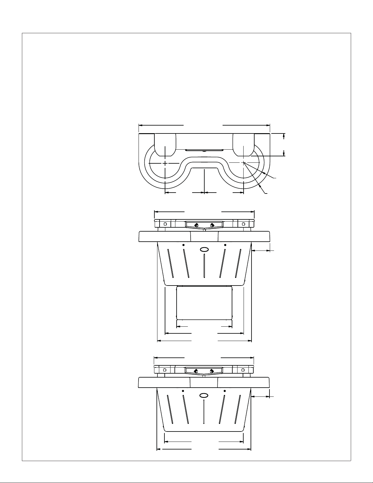
Dimensions - Front and Top Views
50" (1270mm)
Top View
85⁄8
" (219mm)
8" (203mm) Radius
Front View
Standard Frame
Front View
Wall-Hung Frame
15"
(381mm)
38¼" (972mm)
21¼" (540mm)
30" (762mm)
36" (914mm)
38¼" (972mm)
15"
(381mm)
10" (254mm) Radius
7" (178mm)
7" (178mm)
30" (762mm)
36" (914mm)
4 10/19/11 Bradley Corporation • 215-1497 Rev. G; ECM 11-08-011
Installation SS-2N/IR/STD, SS-2N/IR/WH
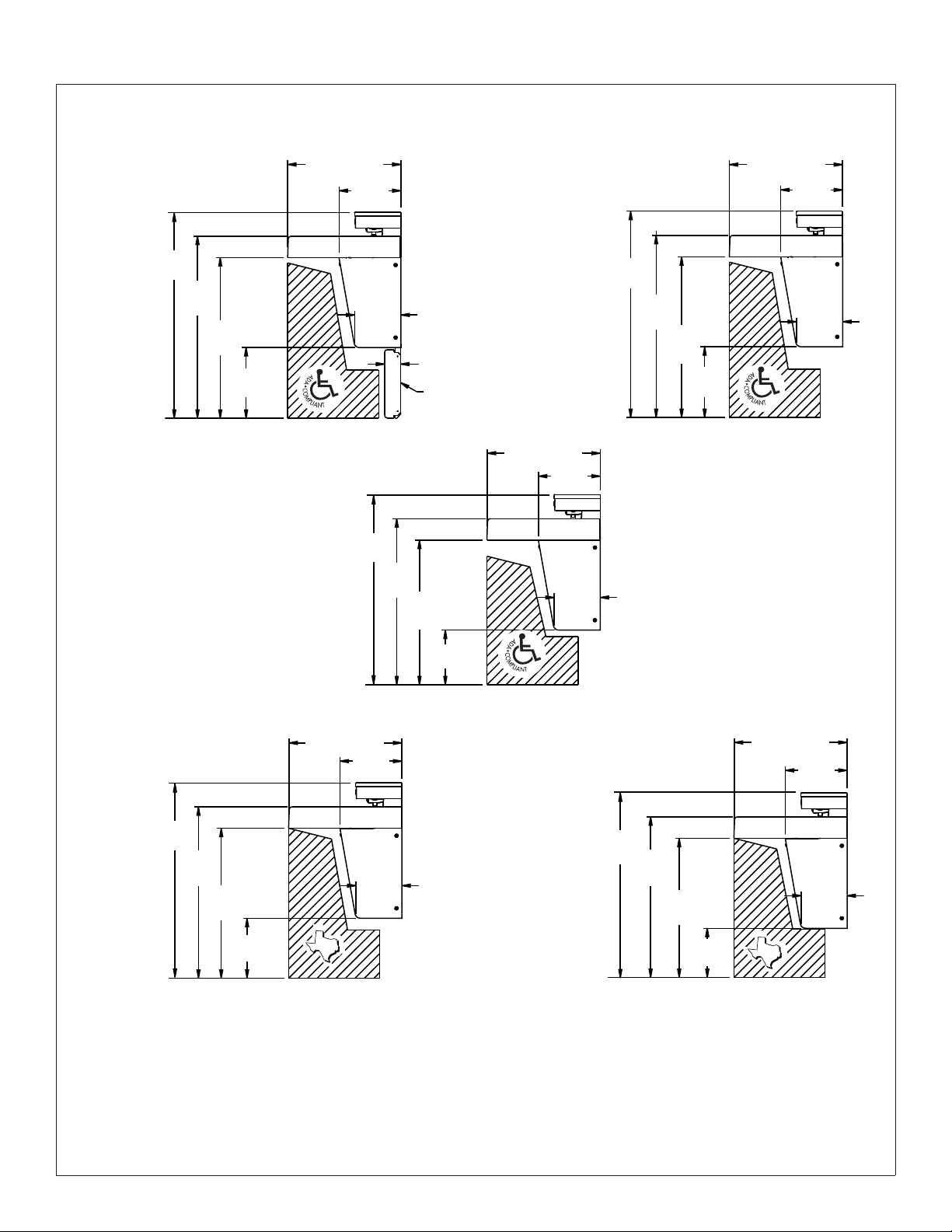
Dimensions - Side Views
Standard
Height
38½"
(978mm)
34"
(864mm)
30"
(762mm)
13¼"
(311mm)
Wall Hung Mounted
at Juvenile Height
Ages: 6 through 12
211⁄8" (537mm)
11½"
(292mm)
(219mm)
(902mm)
8
35½"
5
⁄8"
31"
(787mm)
3" (76mm)
Standard Height Only
27"
(686mm)
Scuff Base on
Wall Hung Mounted
at Standard Height
(978mm)
1
21
⁄8" (537mm)
11½"
(292mm)
5
⁄8"
8
(219mm)
38½"
34"
(864mm)
30"
(762mm)
13¼"
(311mm)
1
⁄8" (537mm)
21
11½"
(292mm)
8
(219mm)
5
⁄8"
Wall Hung Mounted
at TAS Height
Grades: 6
through
8 or 9
36½"
(927mm)
32"
(813mm)
(711mm)
28"
11¼"
(286mm)
211⁄8" (537mm)
11½"
(292mm)
(219mm)
TAS
85⁄8"
10¼"
(260mm)
Wall Hung Mounted
at TAS Height
Grades: Pre-K
through 5 or 6
34½"
(876mm)
30"
(762mm)
26"
(660mm)
9¼"
(235mm)
211⁄8" (537mm)
(292mm)
TAS
11½"
85⁄8"
(219mm)
Bradley Corporation • 215-1497 Rev. G; ECM 11-08-011 10/19/11 5
 Loading...