

Bradley Express SS Series, Express SS-2/WH97, Express SS-2/TT Installation Instructions Manual
SS-2/TT/WH97
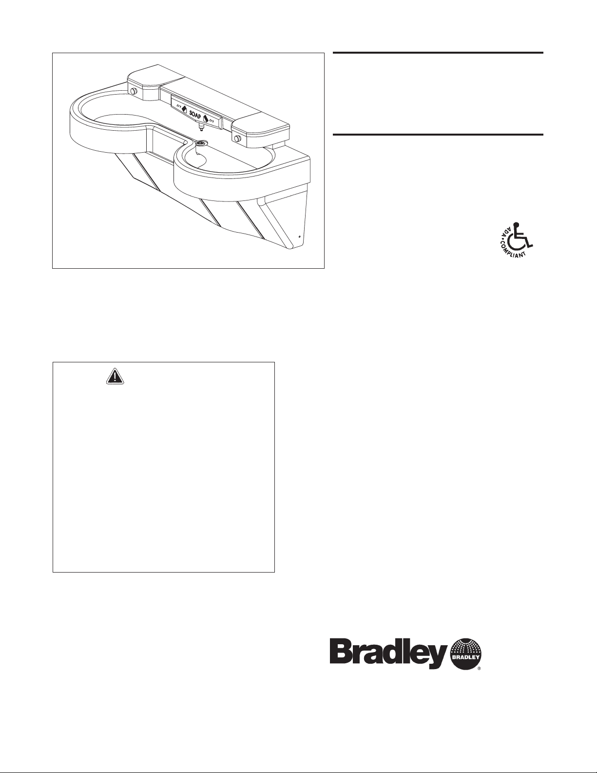
Express® Lavatory
System SS-Series
Express® Lavatory Systems
are ADA compliant.
P.O. Box 309, Menomonee Falls, WI 53052-0309
TEL. 1-800-BRADLEY FAX 262-251-5817
http://www.bradleycorp.com
Table of Contents
Pre-Installation Information . . . . . . . . . . . . . . . .2
Dimensions . . . . . . . . . . . . . . . . . . . . . . . . . . . . .3
Installation Instructions . . . . . . . . . . . . . . . . . 4-9
Cleaning and Maintenance Instructions . . . . . .10
Soap Dispenser Maintenance . . . . . . . . . . .11-12
Wiring Diagram . . . . . . . . . . . . . . . . . . . . . . . .12
Assembly of Components . . . . . . . . . . . . . .13-14
Check Valve Troubleshooting . . . . . . . . . . . . . .15
Solenoid Valve Troubleshooting . . . . . . . . .15-16
Vernatherm™ Thermostatic Mixing Valve . . . .17
IMPORTANT
Read this entire installation manual
to ensure proper installation, then
file these instructions with the
owner or maintenance department.
Flush all the water supply lines
before making connections.
Wall anchors used must have a
minimum pull-out rating of 1,000
lbs.
Product warranties may be found
under "Product Information" on our
web site at www.bradleycorp.com.
Installation
Instructions
OBSOLETE
215-1453 Rev. B; EN 08-805
© 2008 Bradley Corporation
Page 1 of 17 4/24/08

2
Express® Lavatory System SS-Series
SS-2/TT/WH97 Installation - Obsolete
4/24/08 Bradley Corporation • 215-1453 Rev. B; EN 08-805
Pre-Installation Information
Barrier-free and ADA compliant - standard height mounting
The SS-2/TT/WH97 Express® Lavatory System must have a rim height of 34" above finished floor
to be compliant with Americans with Disabilities Act (ADA). When mounted at 34" rim height,
the Express® meets ADA, ANSI and UFAS requirements for barrier-free clearances, reaches and
controls. Always check local codes and ordinances for compliance.
Barrier-free and ADA compliant - juvenile height mounting
The SS-2/TT/WH97 Express® Lavatory System must have a rim height no higher than 31" above
finished floor to be compliant with Americans with Disabilities Act (ADA) Accessibility
Guidelines for Buildings and Facilities: Building Elements Designed for Children's Use; Final
Rule.
Touch TIme™ switch and solenoid
Each sprayhead is controlled by a Touch Time™ switch, enabling each user to activate a single
flow of water. Each valve uses less than half the maximum of hot water allowed by the
ANSI/ASHRAE/IESNA 90.1-1989 Standard.
Supplies required for installation:
• (8) 3/8" wall anchors, bolts and washers to mount frame and bowl (minimum
pull-out rating of 1,000 lbs.) and bowl to wall
• 1/2" NPT tempered supply piping
• 1-1/2" NPT drain piping
• 110 volt electrical outlet for 110/24 VAC plug-in transformer (supplied)
3
Express® Lavatory System SS-Series
Installation - Obsolete SS-2/TT/WH97
Bradley Corporation • 215-1453 Rev. B; EN 08-805 4/24/08
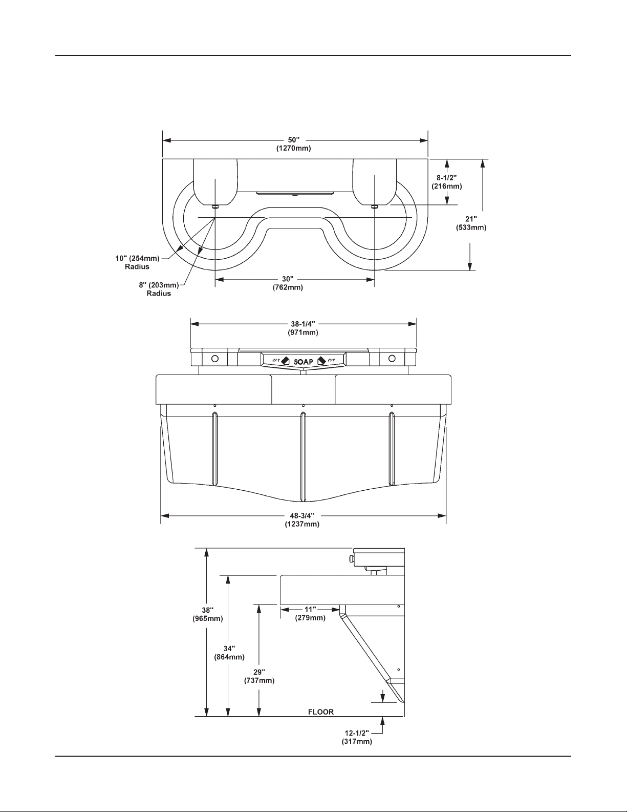
SS-2/TT/WH97 Express® Lavatory System Dimensions
Standard Height Mounting
4
Express® Lavatory System SS-Series
SS-2/TT/WH97 Installation - Obsolete
4/24/08 Bradley Corporation • 215-1453 Rev. B; EN 08-805
Installation Instructions
Step 1: Rough in
NOTE: See Figure 1a below (for Standard Height) and Figure 1b on page 5 (for Juvenile Height)
when roughing in the Express®.
IMPORTANT: Flush the supply lines before making connections. Debris in supply
lines will cause the valves to malfunction.
IMPORTANT: Turn OFF electrical power to the outlet when installing the Express®.
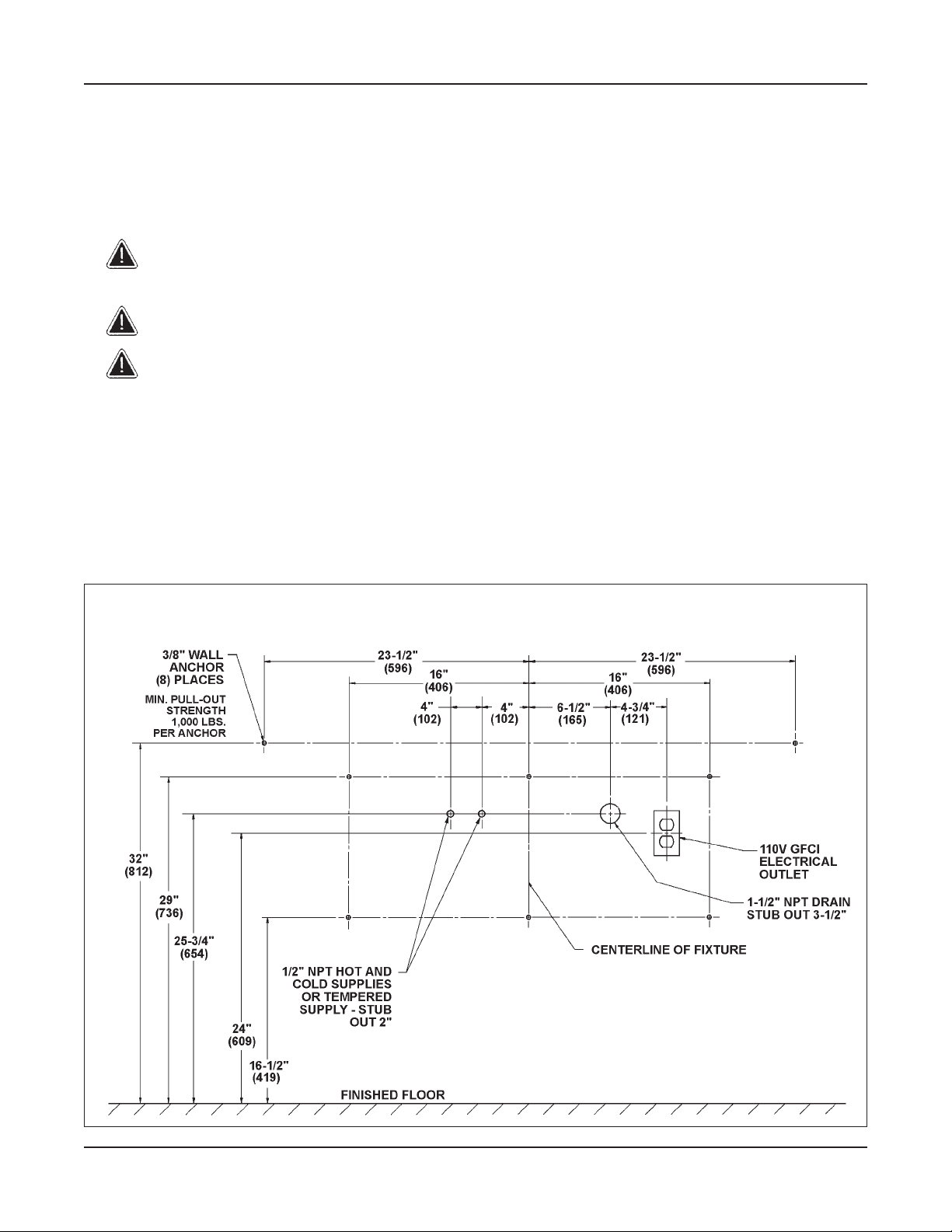
IMPORTANT: Dimensions shown in Figure 1a are for an SS-2/TT/WH97
Express® only.
1. Rough in 1/2" NPT hot and cold supply lines through wall at dimensions shown.
2. Rough in 1-1/2" NPT drain waste connection through wall at dimensions shown.
3. Install the 110 volt GFCI electrical outlet per local code at the location shown in Figure 2 on
page 5.
4. Install eight 3/8" wall anchors with a minimum pull-out rating of 1,000 lbs. (supplied by
installer) at the locations shown in Figure 1a below or Figure 1b on page 5.
Figure 1a
SS-2/TT/WH97 Express® Lavatory System Dimensions
Standard Height Mounting
5
Express® Lavatory System SS-Series
Installation - Obsolete SS-2/TT/WH97
Figure 2
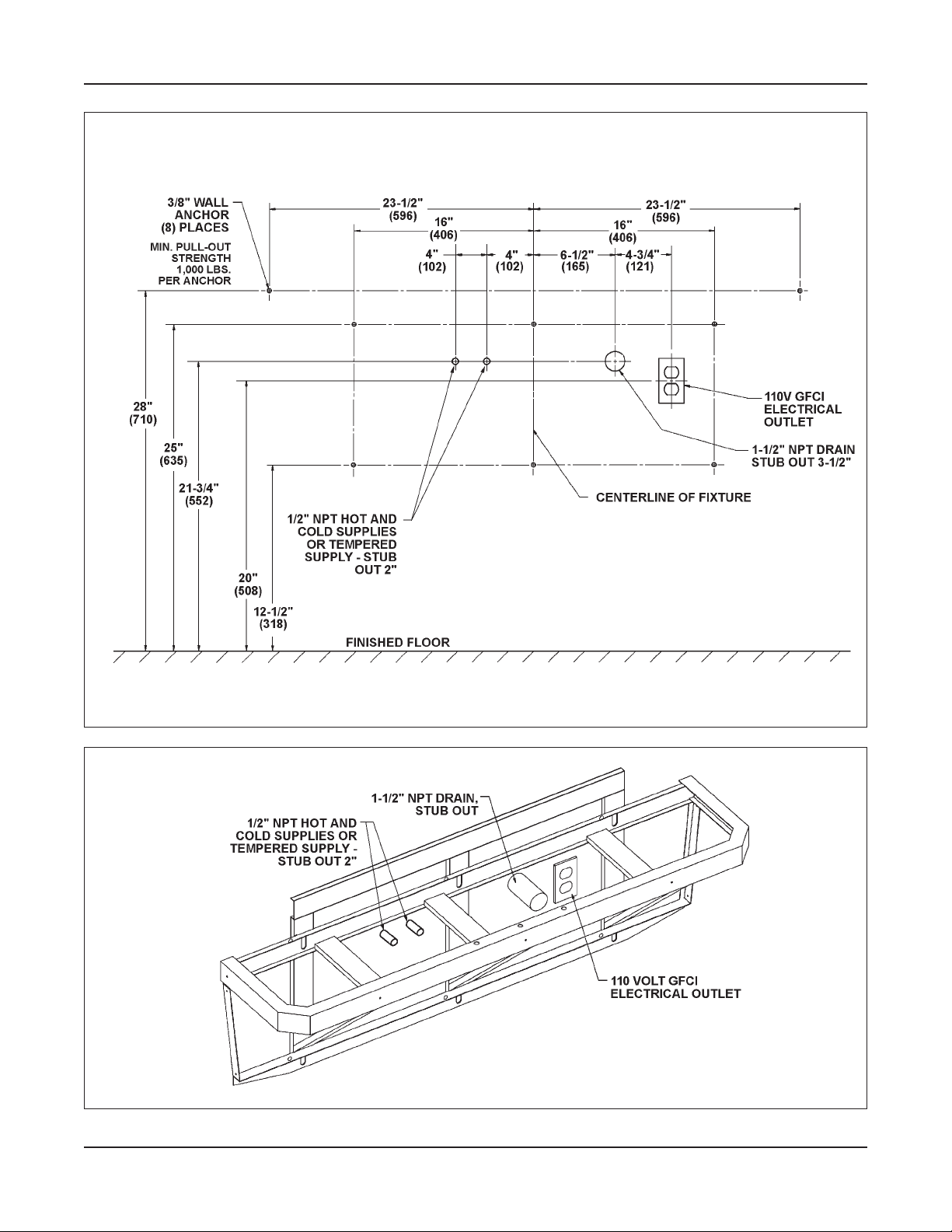
Figure 1b
Bradley Corporation • 215-1453 Rev. B; EN 08-805 4/24/08
SS-2/TT/WH97 Express® Lavatory System Dimensions
Juvenile Height Mounting
6
Express® Lavatory System SS-Series
SS-2/TT/WH97 Installation - Obsolete
4/24/08 Bradley Corporation • 215-1453 Rev. B; EN 08-805
Installation Instructions continued . . .
Step 2: Mount frame to wall
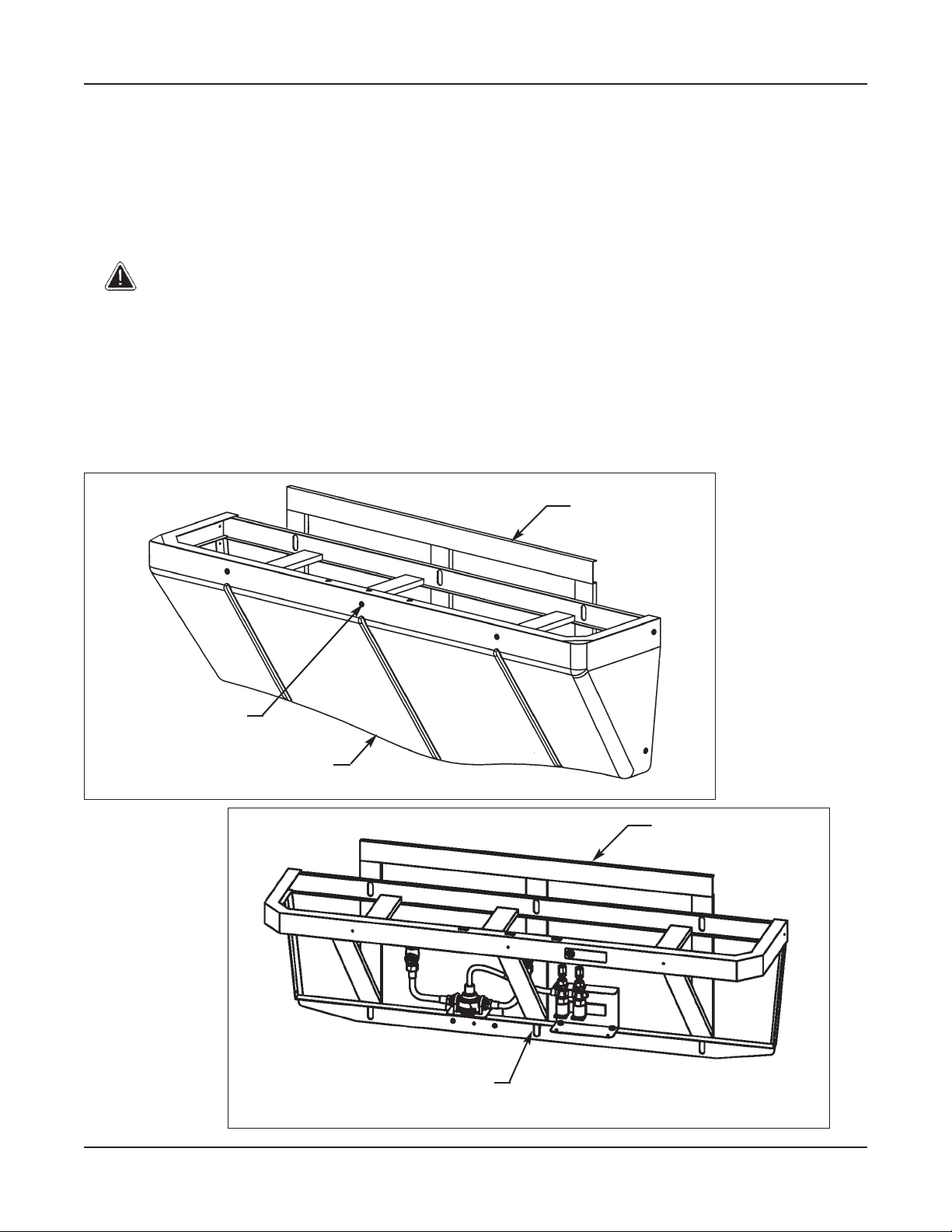
1. Using a T25 bit, remove the seven Torx-head screws securing the panel to the frame and
remove the panel (see Figure 3).
2. Position the frame against the wall, ensuring that it is level.
IMPORTANT: Anchoring the frame to a wall that is not flat may cause the frame to
bend. If necessary, install shims to compensate for wall distortion.
3. Ensure that the back of the frame is flat against the wall. If wall is not flat, insert shims
behind the frame to ensure that it will not bend when anchored.
4. Once you have positioned the frame such that it is level and flat against the wall or shimmed,
use the 3/8" bolts and washers to mount the frame to the wall (see Figure 4).
Installation Instructions continue...
Figure 3
(7) TORX-HEAD
SCREW
FRAME
PANEL
Figure 4
(6) 3/8" BOLTS
AND WASHERS
FRAME
 Loading...