

Bradley Express SS-2 Infrared-to-Touch Time Installation Instructions Manual

Installation Instructions
215-1454 Rev. A; EN 03-808A
© 2004 Bradley Corporation
Page 1 of 2 6-3-2004
P.O. Box 309, Menomonee Falls, WI 53052-0309
TEL. 1-800-BRADLEY FAX 262-251-5817
http://www.bradleycorp.com
Express® SS-2 Infrared-to-Touch Time™ Retrofit Kit
Step 1: Remove existing infrared components
NOTE: Shut off the water supply and unplug the transformer from the outlet before installation.
1. Using a T25 bit, remove the Torx-head screws securing the access panel to the frame.
Remove the access panel and set it aside.
2. Unplug the sensor connector plug from the solenoid rack located in the frame. Disconnect the
four wires attached to the solenoids.
3. Unplug the transformer connector plug from the solenoid rack located in the frame and
remove the transformer.
4. Remove the eight Phillips-head screws located on the bottom of the sprayhead body.
Carefully lift off the Terreon® cover and set it aside.
5. Inside the sprayhead body, remove the two sensor eyes from each of the two sensor windows.
Unscrew the nut from each of the sensor windows. Save the nuts and discard the windows.
6. Pull the sensor connector plug and wire harness up through the frame and sprayhead body.
Discard the sensors and wire harness.
Step 2: Install Touch Time™ switches
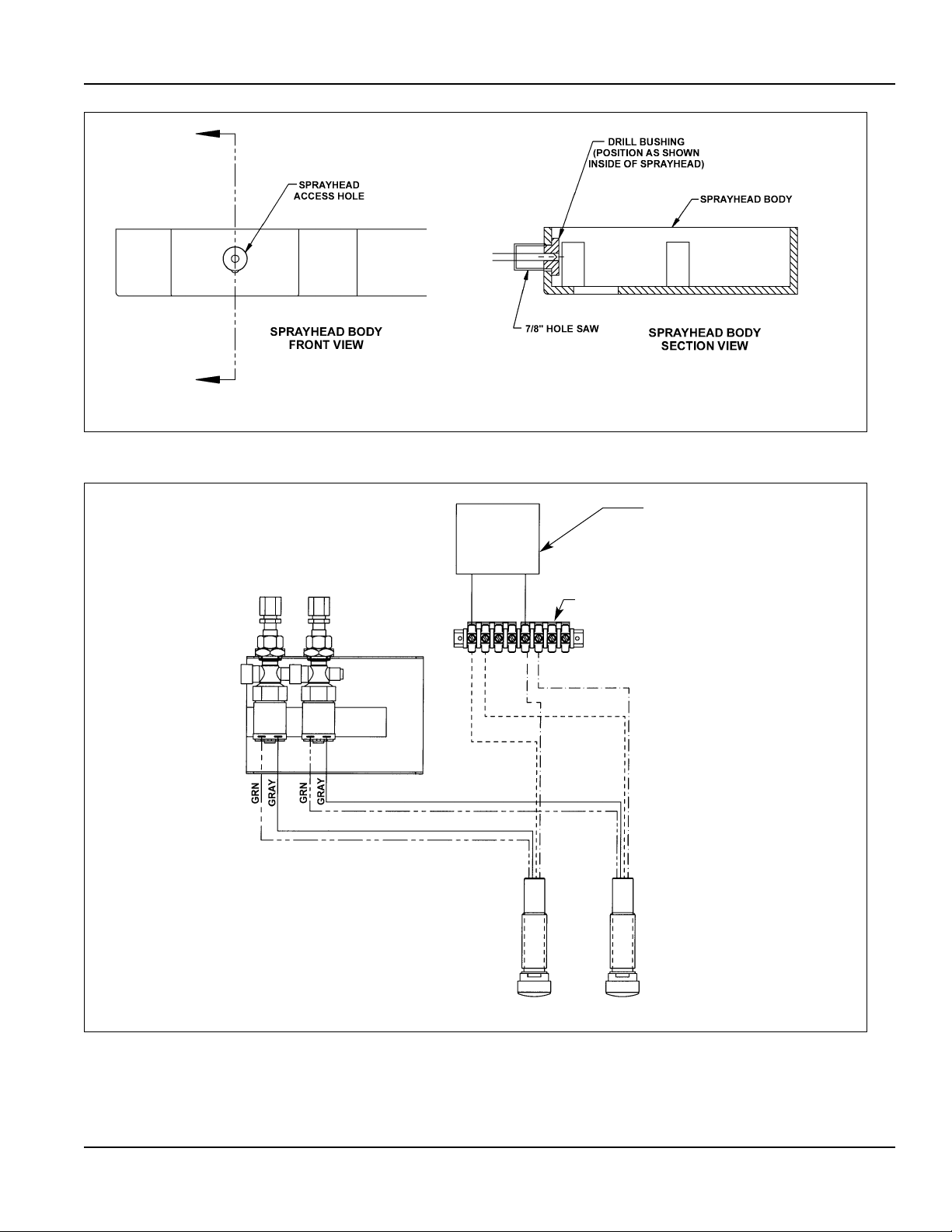
1. Carefully enlarge the two existing 13/16" holes located on the front face of the sprayhead
body using a 7/8" hole saw. Use the drill bushing provided to guide the hole saw while
drilling (see Figure 1 on page 2).
2. Insert the Touch Time™ switch into the hole, pushing the wires through first. Using the 1/2"
nut from the sensor windows, thread the wires through and securely fasten the Touch Time™
switch to the sprayhead body.
3. Run the Touch Time™ wires down through the sprayhead/bowl assembly into the frame and
connect the wires to the solenoids and terminal block (see wiring diagram on page 2).
4. Attach the terminal block provided to the frame near the solenoid rack using the hook-andloop fastener provided.
5. Connect the two leads from the transformer provided to the terminal block. Plug the transformer
into the 120V outlet (refer to the wiring diagram on page 2).
6. Turn on the hot and cold water supplies. Trigger the Touch Time™ push buttons and check
for proper function (the timing is electronically controlled and set at 15 seconds). Reattach
the sprayhead cover and access panel.
NOTE: Activation of the push button takes place only when it is released, thereby preventing
“hold open” activation.
Express® SS-2 Infrared-to-Touch Time™ Retrofit Kit
Installation Instructions
2Bradley Corporation • 215-1454 Rev. A; EN 03-808A
Figure 1
TERMINAL BLOCK
269-1311
SOLENOID
RACK
TT1 TT2
WIRING DIAGRAM
S1 S2
Figure 2
120v
TRANSFORMER
S83-134
BLK
BRN
BRN
BLK
6-3-2004
 Loading...