

Bradley Express MG-2/NDT, Express MG Series Installation Manual
IMPORTANT!
Read this entire installation manual to ensure proper installation.
When finished with the installation, file this manual with the owner or
maintenance department.
Separate parts from packaging and make sure all parts are accounted
for before discarding any packaging material. If any parts are
missing, do not begin installation until you obtain the missing parts.
Make sure that all water supply lines have been flushed and then
completely turned off before beginning installation. Debris in supply
lines can cause valves to malfunction.
Hardware supplied by installer must be appropriate for wall
construction. Wall anchors used must have a minimum pull-out
rating of 1,000 lbs.
Product warranties may be found under "Product Information" on our
web site at www.bradleycorp.com.
Installation
MG-2/NDT
Express® Lavatory System MG-Series
with ndite™ Infrared Control
Express® Lavatory
Systems are ADA and
TAS compliant.
Patents Pending
P.O. Box 309, Menomonee Falls, WI 53052-0309
Phone: 1-800-BRADLEY Fax: (262) 251-5817
http:\\www.bradleycorp.com
215-1587 Rev. C; EN 06-915
© 2007 Bradley Corporation
Page 1 of 22 2/12/07
Installation
A
D
A
C
O
M
P
T
L
N
I
A
TAS
Packing List
IS
H
T
E
ID
S
P
U

MG-2/NDT Installation
Table of Contents
Supplies Required By Installer . . . . . . . . . . . . . . . . . . . . . . . . . . . . . . . . . . . . . . .2
MG-2/NDT Dimensions - Front, Top and Side Views . . . . . . . . . . . . . . . . . .3–4
Installation Instructions
Step 1 Rough-Ins . . . . . . . . . . . . . . . . . . . . . . . . . . . . . . . . . . . . . . . . . . . . .5–6
Step 2 Rough-In Wall Anchors . . . . . . . . . . . . . . . . . . . . . . . . . . . . . . . . . . . .7
Step 3 Mount Frame to Wall . . . . . . . . . . . . . . . . . . . . . . . . . . . . . . . . . . . . . .8
Step 3 Install Bowl Assembly . . . . . . . . . . . . . . . . . . . . . . . . . . . . . . . . . . . . . . .
8
Step 4 Connect Supply and Drain . . . . . . . . . . . . . . . . . . . . . . . . . . . . . . . . . .9
Step 5 Connect Electrical and Supply Tubing . . . . . . . . . . . . . . . . . . . . . . . .10
Step 6 Complete Installation . . . . . . . . . . . . . . . . . . . . . . . . . . . . . . . . . .11–12
Cleaning and Maintenance Instructions . . . . . . . . . . . . . . . . . . . . . . . . . . . . . . .13
Assembly of Components . . . . . . . . . . . . . . . . . . . . . . . . . . . . . . . . . . . . . .14–17
Troubleshooting ndite™ components . . . . . . . . . . . . . . . . . . . . . . . . . . . . .18–19
Solenoid Valve Components . . . . . . . . . . . . . . . . . . . . . . . . . . . . . . . . . . . . . . .20
Thermostatic Mixing Valve Maintenance and Troubleshooting . . . . . . . . . . . .21
Thermostatic Mixing Valve Parts . . . . . . . . . . . . . . . . . . . . . . . . . . . . . . . . . . . .22
Cleaning the Strainer . . . . . . . . . . . . . . . . . . . . . . . . . . . . . . . . . . . . . . . . . . .21-22
2 2/12/07 Bradley Corporation • 215-1587 Rev. C; EN 06-915
Supplies Required by Installer
(8) 3/8" wall anchors, bolts and 1" min. O.D. washers to mount main frame and bowl to wall (minimum
pull-out rating of 1,000 lbs.)
1/2" NPT hot and cold supply piping
1-1/2" NPT drain piping
Installation MG-2/NDT
3Bradley Corporation • 215-1587 Rev. C; EN 06-915 2/12/07
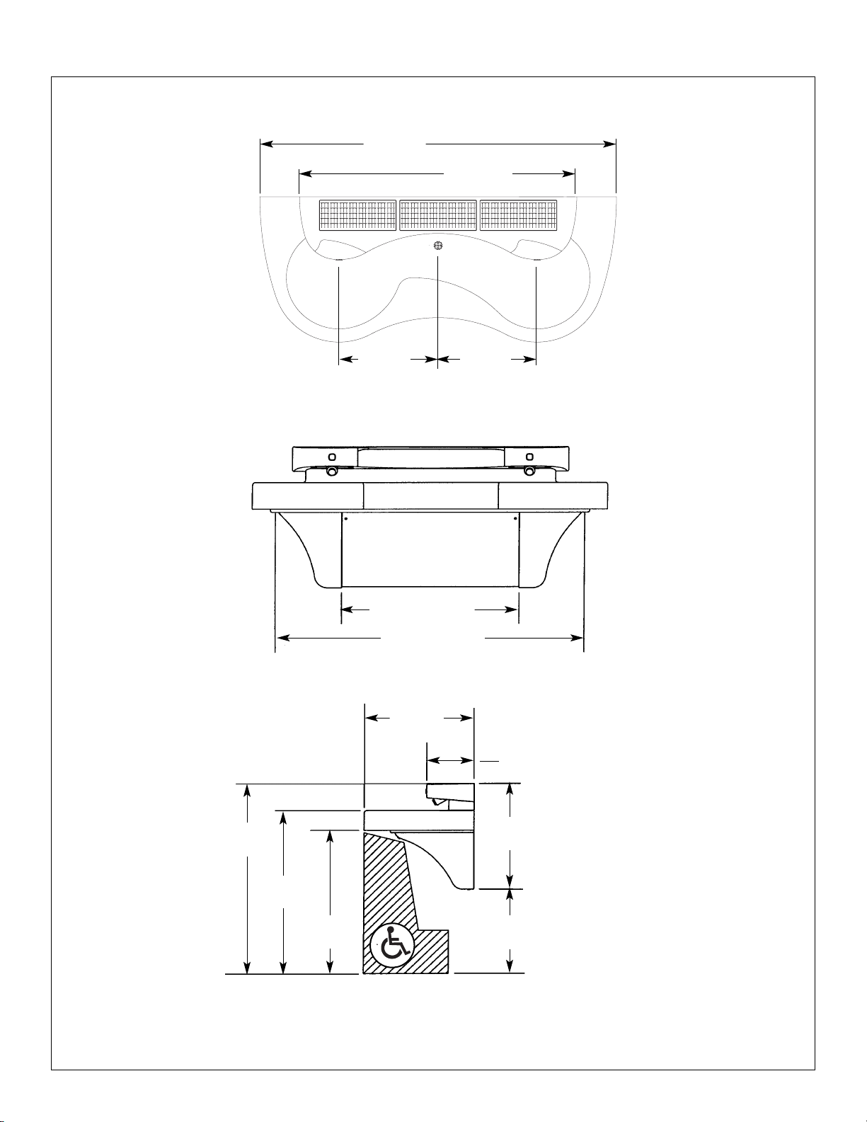
MG-2/NDT Express® Lavatory System Dimensions
*Subtract 4" (102mm) from vertical dimensions for compliance with ADA guidelines for children's use.
A
D
A
C
O
M
P
L
I
A
N
T
22"
(559mm)
*39"
(991mm)
*33-1/2"
(851mm)
*29-1/2"
(749mm)
*17-1/2"
(445mm)
21-1/2"
(546mm)
9-1/2"
(241mm)
27" (686mm)
47" (1194mm)
54"
(1372mm)
42"
(1067mm)
15"
(381mm)
15"
(381mm)
MG-2/NDT Express® Lavatory System Dimensions continued . . .
MG-2/NDT Installation
4 2/12/07 Bradley Corporation • 215-1587 Rev. C; EN 06-915
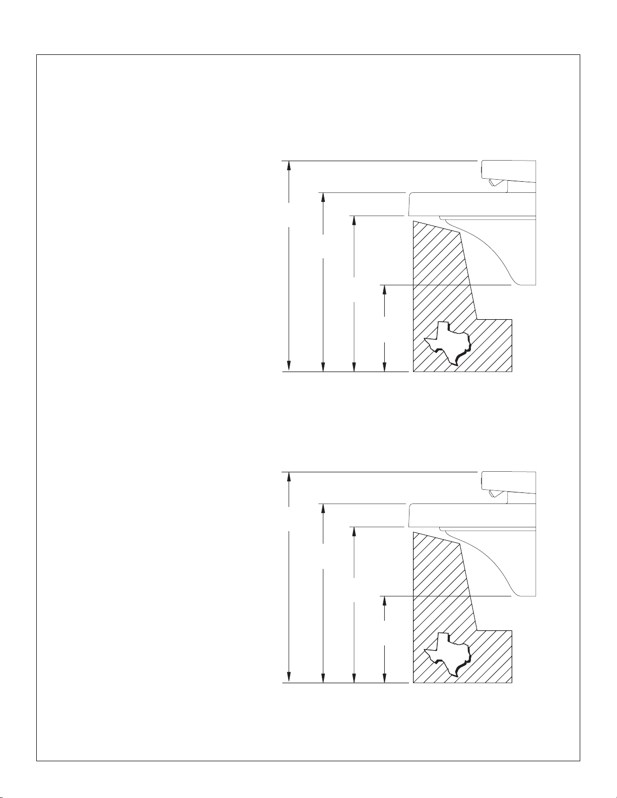
TAS Juvenile Height
Grades 6 thru 8 or 9
TAS Juvenile Height
Grades Pre-K thru 5 or 6
37-1/2"
(952mm)
32"
(813mm)
28"
(711mm)
16"
(406mm)
35-1/2"
(902mm)
30"
(762mm)
26"
(660mm)
14"
(356mm)
TASTAS
TASTAS
Installation MG-2/NDT
5Bradley Corporation • 215-1587 Rev. C; EN 06-915 2/12/07
Installation Instructions
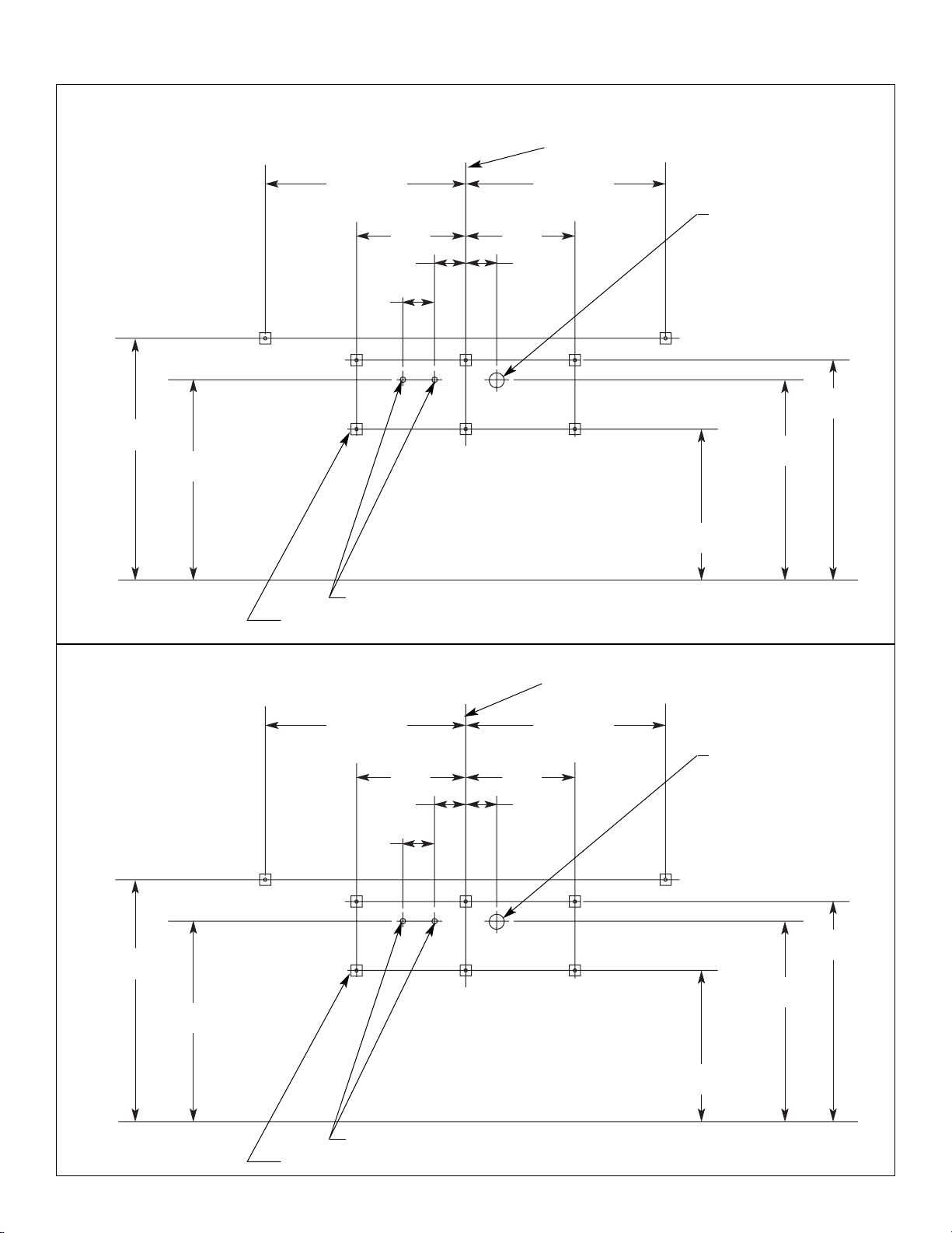
Step 1: Rough in
NOTE: See Figure 1 (below), 1a, 1b (for TAS on page 6) and Figure 2 (on page 7) when roughing in
the MG-2/NDT Express®.
IMPORTANT: Flush the supply lines before making connections. Debris in supply
lines will cause the valves to malfunction.
IMPORTANT: Dimensions shown in Figure 1 are for Standard Height only. Make
sure to follow appropriate dimensions based on configuration and
required rim height. Review appropriate figure before beginning
rough-ins.
1. Rough in 1/2" NPT hot and cold supply lines through wall at dimensions shown.
2. Rough in 1-1/2" NPT drain waste connection through wall at dimensions shown.
4"
(102)
FLOOR
APPROX. DIMENSION
14"
(356)
14"
(356)
*28-1/4"
(718)
*25-3/4"
(654)
1/2" NPT HOT AND COLD
SUPPLIES OR TEMPERED
SUPPLY – STUB OUT 2"
1-1/2" NPT DRAIN
STUB OUT 2"
3/8" WALLANCHORS (8) PLACES MIN. PULL-OUT
STRENGTH 1000 LBS. PER ANCHOR
*Juvenile Height Mounting:
Subtract 4" (102mm) from vertical dimensions for compliance
with ADA guidelines for children's use.
Figure 1
Standard Height Mounting
CENTERLINE
OF FIXTURE
*26"
(660)
*31-1/2"
(800)
*19-1/2"
(495)
4"
(102)
4" (102)
H
C
16-1/2"
(419)
25-1/2" (648)
APPROX. DIMENSION
25-1/2" (648)
A A
B
BB B
B
B
MG-2/NDT Installation
6 2/12/07 Bradley Corporation • 215-1587 Rev. C; EN 06-915
TAS — Texas Accessibility Standards:
Juvenile Height (grades Pre-K thru 5 or 6)
Figure 1b
4"
(102)
FLOOR
APPROX. DIMENSION
14"
(356)
14"
(356)
26-3/4"
(679)
24-1/4"
(616)
1/2" NPT HOT AND COLD SUPPLIES OR TEMPERED SUPPLY – STUB OUT 2"
1-1/2" NPT DRAIN
STUB OUT 2"
3/8" WALLANCHORS (8) PLACES MIN. PULL-OUT STRENGTH 1000 LBS. PER ANCHOR
CENTERLINE OF FIXTURE
18"
(457)
4"
(102)
4" (102)
H
C
16-1/2"
(419)
25-1/2" (648)
APPROX. DIMENSION
25-1/2" (648)
A A
B
BB B
B
B
30"
(762)
24-1/2"
(622)
Figure 1a
4"
(102)
FLOOR
APPROX. DIMENSION
14"
(356)
14"
(356)
24-3/4"
(629)
22-1/4"
(565)
1/2" NPT HOT AND COLD SUPPLIES OR TEMPERED SUPPLY – STUB OUT 2"
1-1/2" NPT DRAIN
STUB OUT 2"
3/8" WALLANCHORS (8) PLACES MIN. PULL-OUT STRENGTH 1000 LBS. PER ANCHOR
CENTERLINE OF FIXTURE
22-1/2"
(572)
28"
(711)
16"
(406)
4"
(102)
4" (102)
H
C
16-1/2"
(419)
25-1/2" (648)
APPROX. DIMENSION
25-1/2" (648)
A A
B
BB B
B
B
TAS — Texas Accessibility Standards:
Juvenile Height (grades 6 thru 8 or 9)
Installation MG-2/NDT
7Bradley Corporation • 215-1587 Rev. C; EN 06-915 2/12/07
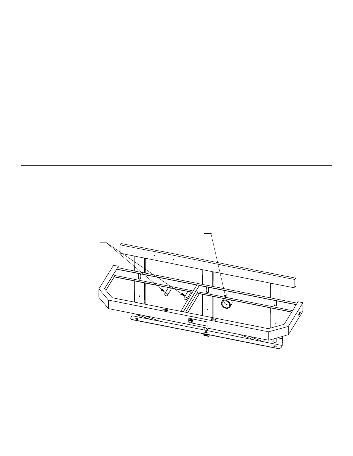
Installation Instructions continued . . .
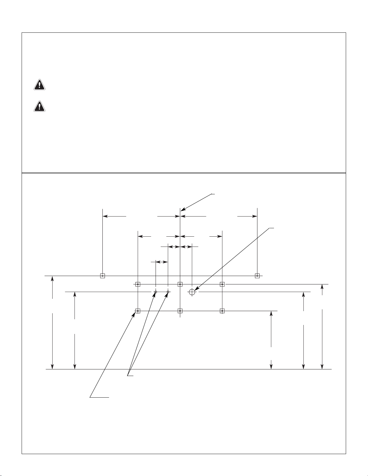
Step 2: Rough in wall anchors
1. Install six 3/8" wall anchors with a minimum pull-out rating of 1,000 lbs. (supplied by installer) at
the locations marked (ref. location “B” shown in Figure 1, 1a or 1b on pages 5-6).
NOTE: The dimensions for the wall anchors at location “A” are for reference only.
2. On the back of the bowl, measure the distance between the 3/4" bowl mounting holes. Divide this
measurement in half. Measure and mark this dimension on the wall to the left of the centerline
and to the right of the centerline. Install two 3/8" wall anchors with a minimum pull-out rating of
1,000 lbs. (supplied by installer) at the locations marked (ref. location “A” shown in Figure 1, 1a
or 1b on pages 5-6).
NOTE: The anchors will be used to mount the Express® bowl and frame to the wall.
Figure 2
1-1/2" NPT DRAIN
STUB OUT 2"
1/2" NPT HOT AND
COLD SUPPLIES OR
TEMPERED SUPPLY.
STUB OUT 2"
 Loading...