

Bradley Express MG Series, Express MG-3 Infrared Installation Instruction
Installation
MG-3 Infrared
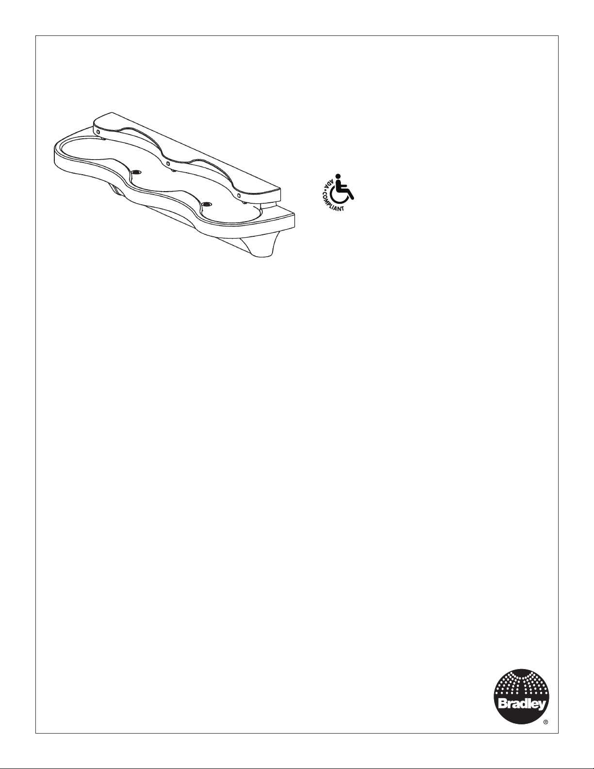
Express® Lavatory System - MG Series
with Adaptive Infrared
Table of Contents
Pre-Installation Information ................................................ 2
Supplies Required .............................................................2
Dimensions ........................................................................ 3
Supplies Required .............................................................3
Rough-Ins .......................................................................... 4
Mount the Frame ...............................................................5
Install the Bowl ..................................................................5
Connect the Supply ........................................................... 6
Install the Drains ................................................................ 7
Connect the Electrical and Tubing .....................................7
Adjust the Temperature...................................................... 8
Components ......................................................................9
Sensor Assembly and Valve Access ...............................10
Cleaning and Maintenance .............................................. 11
Troubleshooting ..........................................................12-14
215-1322 Rev. Y; ECN 17-08-010
© 2017 Bradley
Page 1 of 14 4/24/2017
Menomonee Falls, WI 53052 USA
P.O. Box 309
800 BRADLEY (800 272 3539)
+1 262 251 6000
bradleycorp.com

MG-3 Infrared Installation
WARNING
Make sure that all water supply lines have been flushed and then completely turned off before beginning
installation. Debris in supply lines can cause valves to malfunction.
Turn OFF electrical power to the electrical outlets, then unplug all electrical units prior to installation. Electrical
power MUST remain off until installation is complete. After installation is complete, turn on the water supply
first, then turn on the electrical power.
Hardware supplied by installer must be appropriate for wall construction. Wall anchors must have a
minimum pull-out rating of 1,000 lbs. Follow appropriate dimensions for standard or juvenile height based on
configuration and required rim height. Overtightening fasteners can damage the Terreon® material. Use caution
when tightening bowl and sprayhead fasteners.
IMPORTANT
Read this entire installation manual to ensure proper installation. For optional soap dispenser, refer to
installation instructions for Express Lavatory System MG-Series document 215-1585. When finished with the
installation, file this manual with the owner or maintenance department. Compliance and conformity to local
codes and ordinances is the responsibility of the installer. Product warranties may be found under "Products"
on our Web site at www.bradleycorp.com.
Separate parts from packaging and make sure all parts are accounted for before discarding any packaging
material. If any parts are missing, do not begin installation until you obtain the missing parts.
Supplies Required
• (8) 3/8" wall anchors, bolts and 1" min. O.D. washers to mount main frame and bowl to wall (minimum pull-out rating
of 1,000 lbs.)
• 1/2" nominal copper tubing for hot and cold supplies and 1-1/2" NPT drain piping
• 120V/220V 50/60 Hz power source using Bradley supplied 120VAC/12V DC plug-in adapter
2 4/24/2017 Bradley • 215-1322 Rev. Y; ECN 17-08-010
Installation MG-3 Infrared
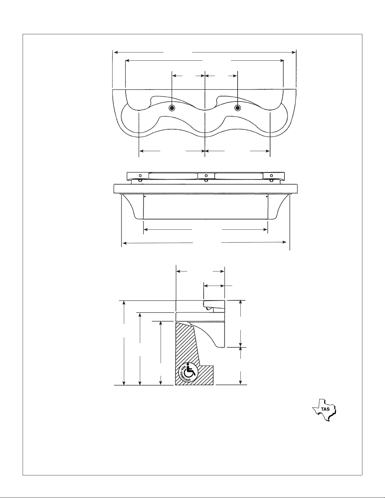
Dimensions
84"
(2134mm)
(381mm)
30"
(762mm)
15"
(1445mm)
(1956mm)
72"
(1829mm)
15"
(381mm)
30"
(762mm)
57"
77"
22"
(559mm)
9½"
(241mm)
21½"
39"
(991mm)*
33½"
(851mm)*
29½"
(749mm)*
* Subtract 4" from all vertical dimensions for Juvenile Height Mounting.
Subtract 3.5" from all vertical dimensions for TAS Juvenile Height Mounting (grades Pre-K through 5 or 6).
Subtract 1.5" from all vertical dimensions for TAS Juvenile Height Mounting (grades 6 through 8 or 9).
(546mm)*
17½"
(445mm)*
Bradley • 215-1322 Rev. Y; ECN 17-08-010 4/24/2017 3
MG-3 Infrared Installation
1
(800mm)*
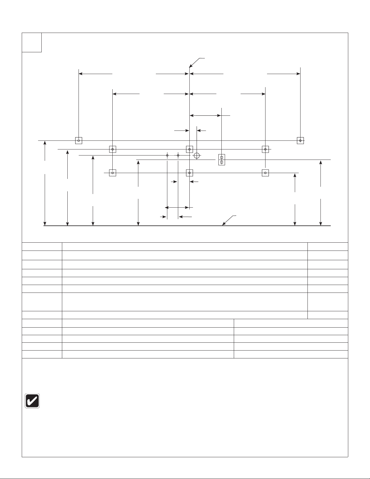
Rough-Ins
31½"
28¼"
(718mm)*
A,E
26"
(660mm)*
40½" (1029mm)
APPROX. DIMENSION
28"
(711mm)
B
B
24"
(610mm)*
2¾"
(70mm)
C1
CENTERLINE OF FIXTURE
40½" (1029mm)
APPROX. DIMENSION
28"
(711mm)
12"
(305mm)
B B
C2
D
4" (102mm)
9" (229mm)
4" (102mm)
H
FLOOR
A,E
BB
24"
19½"
(495mm)*
(610mm)*
CODE DESCRIPTION QTY.
A
B
C1 ½" Nominal Copper Tubing Hot Supply, stub out 2" from wall 1
C2 ½" Nominal Copper Tubing Cold or Tempered Supply, stub out 2" from wall 1
D 1½" NPT Drain, stub out 2" from wall 2
E
H 110V GFCI Protected Electrical Outlet 1
3
/8" Wall Anchors with a minimum pull-out force of 1,000 lbs. for Bowl
3
/8" Wall Anchors with a minimum pull-out force of 1,000 lbs. for Main Frame
On the bowl back, measure the distance between the ¾" bowl mounting holes. Divide this measurement
in half. Measure and mark this dimension on the wall to the left and the right of the centerline. Install two
3
/8" wall anchors with a minimum pull-out rating of 1,000 lbs. (supplied by installer) at locations marked.
RIM HEIGHT * VERTICAL HEIGHT ADJUSTMENTS FIXTURE STYLE
33½" None Standard Height
32" Subtract 1½" TAS, Grades 6 through 8 or 9
29½" Subtract 4" Juvenile Height
30" Subtract 3½" TAS, Pre-K through 5 or 6
The Express® Lavatory System with Adaptive Infrared (model MG-3 Infrared) must have a rim height no higher
than 34" above finished floor to be compliant with Americans with Disabilities Act (ADA). When mounted at 33½"
rim height, the MG-3 Infrared Express® meets ADA, ANSI and UFAS requirements for barrier-free clearances,
reaches and controls. Always check local codes and ordinances for compliance.
2
6
2
4 4/24/2017 Bradley • 215-1322 Rev. Y; ECN 17-08-010
Installation MG-3 Infrared
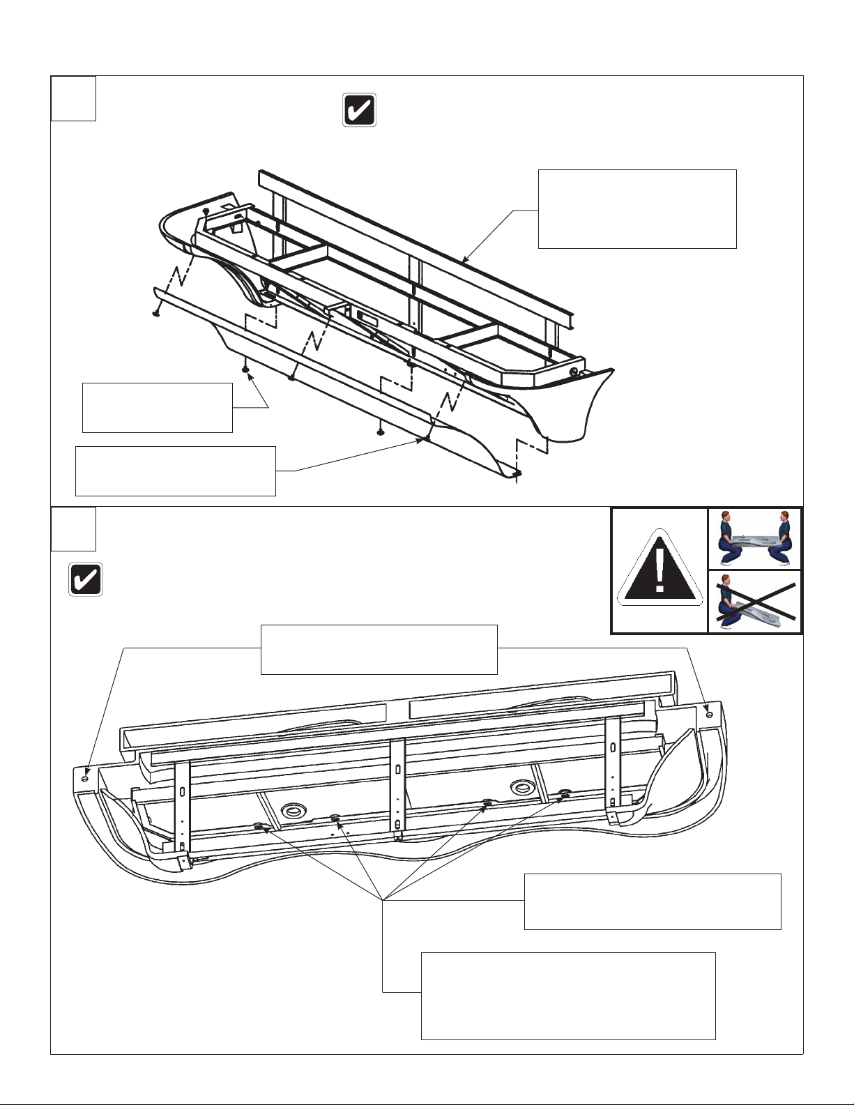
2
Mount the Frame
Loosen, but do not
remove the bottom
A
panel screws.
Remove the top access panel
screws and washers and
B
remove the access panel.
Anchoring the frame to a wall that is not flat may cause the
frame to bend, making it difficult to reinstall the access panels.
If necessary, use shims to compensate for wall distortion.
Once you have positioned
the frame such that it is level
and flat against the wall or
shimmed, use the
C
and washers (6 places) to
mount the frame to the wall.
3
8" bolts
/
3
Install the Bowl
If the fixture has a soap option, refer to the soap system installation
manual (215-1585) before installing the bowl assembly.
Secure the bowl to the wall anchors
with two
B
not overtighten bolts.
3
8" bolts and washers. Do
/
Attach the front of the bowl to the frame
using the four ¼-20 x ½" pan-head screws
and washers provided. Do not tighten
A
screws at this time.
Tighten the screws to secure the bowl assembly to
the frame. Do not overtighten.
If necessary, adjust sprayhead body to fit closely
C
to the wall by adjusting the sprayhead mounting
bolts. Refer to the components illustration for bolt
locations.
Bradley • 215-1322 Rev. Y; ECN 17-08-010 4/24/2017 5
 Loading...