

Bradley Express MG Series, Express MG-3/AST4 Installation Manual
Installation
MG-3/AST4
Express® Lavatory
System - MG Series
with Pushbutton
Air Valve
Table of Contents
Pre-Installation Information ...................2
Dimensions..................................3
Supplies Required ........................... 3
Rough-Ins ...................................4
Installation . . . . . . . . . . . . . . . . . . . . . . . . . . . .5–8
Components . . . . . . . . . . . . . . . . . . . . . . . . . .9–10
Cleaning and Maintenance . . . . . . . . . . . . .11–12
Check Valve Troubleshooting . . . . . . . . . . . . . . .12
Metering Air Valve Troubleshooting . . . . . . . . . .13
Thermostatic Mixing Valve Troubleshooting . . . .14
A
D
A
•
C
O
M
P
L
T
I
A
N
215-1323 Rev. P; EN 07-814
© 2007 Bradley Corporation
Page 1 of 14 12/10/07
P.O. Box 309, Menomonee Falls, WI 53052-0309
Phone: 1-800-BRADLEY Fax: 262-253-4161
www.bradleycorp.com

MG-3/AST4 Installation
IMPORTANT!
Installation
Read this entire installation manual to ensure proper installation. For optional
soap dispenser, refer to Installation Instructions for Express® Lavatory System
MG-Series document 215-1585. When fi nished with the installation, fi le this manual
with the owner or maintenance department. Compliance and conformity to local
codes and ordinances is the responsibility of the installer.
Packing List
Separate parts from packaging and make sure all parts are accounted for
•
•
•
IS
H
T
E
D
I
S
P
U
before discarding any packaging material. If any parts are missing, do not begin
•
installation until you obtain the missing parts.
Make sure that all water supply lines have been fl ushed and then completely
turned off before beginning installation. Debris in supply lines can cause valves to
malfunction.
Turn OFF electrical power to the electrical outlets, then unplug all electrical
units prior to installation. Electrical power MUST remain off until installation is
completed. After installation is complete, turn on the water supply fi rst, then turn
on the electrical power.
Hardware supplied by installer must be appropriate for wall construction. Wall
anchors used must have a minimum pull-out rating of 1,000 lbs. Overtightening
fasteners can damage the Terreon
®
material. Use caution when tightening bowl and
sprayhead fasteners.
Product warranties may be found under “Product Information” on our web site at
www.bradleycorp.com.
2 12/10/07 Bradley Corporation • 215-1323 Rev. P; EN 07-814
Installation MG-3/AST4
A
D
A
•
C
O
M
P
L
I
A
N
T
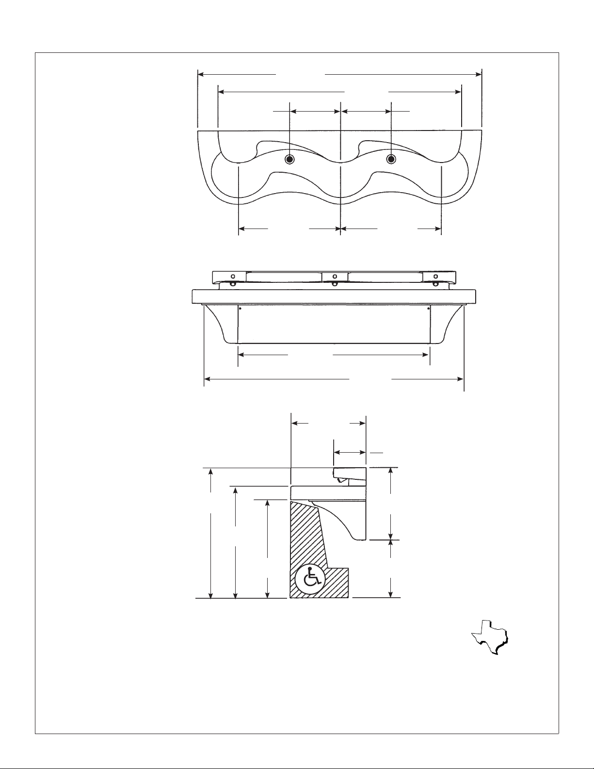
Dimensions
15"
(381mm)
(762mm)
84"
(2134mm)
30"
72"
(1829mm)
15"
(381mm)
30"
(762mm)
57"
(1445mm)
77"
(1956mm
22"
(559mm)
9-1/2"
(241mm)
39"
(991mm)*
21-1/2"
(546mm)
33-1/2"
(851mm)*
29-1/2"
(749mm)*
17-1/2"
(445mm)*
* Subtract 4" from all vertical dimensions for Juvenile Height Mounting.
Subtract 3.5" from all vertical dimensions for TAS Juvenile Height Mounting (grades Pre-K through 5 or 6).
Subtract 1.5" from all vertical dimensions for TAS Juvenile Height Mounting (grades 6 through 8 or 9).
TAS
Supplies Required:
• (8) 3/8" wall anchors, bolts and 1" min. O.D. washers to mount main frame and bowl to wall (minimum pull-out rating of
1,000 lbs.)
• 1/2" NPT hot and cold supply piping and 1-1/2" NPT drain piping
• Optional: 240/208 volt or 277 volt electrical box for optional electrical tankless water heater
Bradley Corporation • 215-1323 Rev. P; EN 07-814 12/10/07 3
MG-3/AST4 Installation
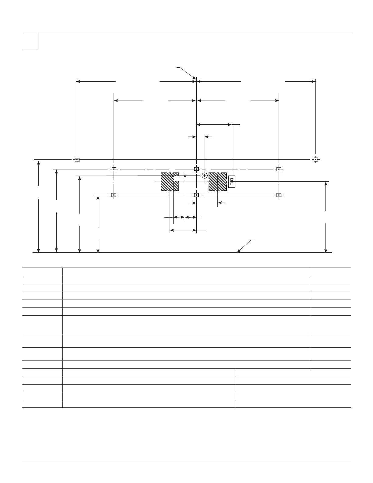
1
Rough-Ins
CENTERLINE OF FIXTURE
40-1/2" (1029mm) 40-1/2" (1029mm)
APPROX. DIMENSION
APPROX. DIMENSION
31-1/2"
(800mm)*
(718mm)*
28-1/4"
B, E
26"
(660mm)*
19-1/2"
(496mm)*
28"
(711mm)
2-3/4"
(70mm)
C2
C1
A
4"
(102mm)
D
FG
7-1/4"
(184mm)
4"
(102mm)
9"
(229mm)
28"
(711mm)
(305mm)
H
12"
B, E
AAA
AA
(610mm)*
FLOOR
CODE DESCRIPTION QTY.
A
B
C1
C2
D
E
F
G
H
3/8" Wall Anchors with a minimum pull-out force of 1,000 lbs. for Frame
3/8" Wall Anchors with a minimum pull-out force of 1,000 lbs. for Bowl
1/2" NPT Hot Supply, stub out 2" from wall
1/2" NPT Cold or Tempered Supply, stub out 2" from wall
1-1/2" NPT Drain, stub out 2" from wall
On the bowl back, measure the distance between the 3/4" bowl mounting holes. Divide this measurement
in half. Measure and mark this dimension on the wall to the left and the right of the centerline. Install two
3/8" wall anchors with a minimum pull-out rating of 1,000 lbs. (supplied by installer) at locations marked.
Water Heater Option #1: Rough in appropriate electrical supply per local code (recommended location for
240/208V electrical box [6"L x 3"W x 6"H])
Water Heater Option #2: Rough in appropriate electrical supply per local code (recommended location for
240/208V electrical box [6"L x 3"W x 6"H])
110V GFCI Protected Electrical Outlet, I.R. and touch time only
RIM HEIGHT * VERTICAL HEIGHT ADJUSTMENTS FIXTURE STYLE
33-1/2" None Standard Height
29-1/2" Subtract 4" Juvenile Height
32" Subtract 1-1/2" TAS, Grades 6 through 8 or 9
30" Subtract 3-1/2" TAS, Pre-K through 5 or 6
24"
6
2
1
1
1
2
1
1
1
NOTE: The Express® Lavatory System with Pushbutton Air Valve (model MG-3/AST4) must have a rim height no higher
than 34" above finished floor to be compliant with Americans with Disabilities Act (ADA). When mounted at
33-1/2" rim height, the MG-3/AST4 Express® meets ADA, ANSI and UFAS requirements for barrier-free clearances,
reaches and controls. Always check local codes and ordinances for compliance.
4 12/10/07 Bradley Corporation • 215-1323 Rev. P; EN 07-814
Installation MG-3/AST4
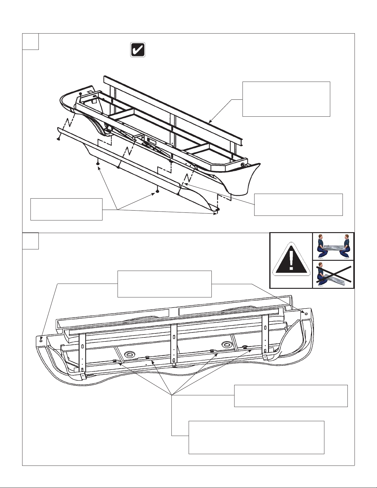
2
Mount the Frame
Anchoring the frame to a wall that is not flat may cause the frame to bend,
making it difficult to reinstall the access panels. If necessary, use shims to
compensate for wall distortion.
Once you have positioned
the frame such that it is level
and flat against the wall or
shimmed, use the 3/8" bolts
C
and washers (6 places) to
mount the frame to the wall.
Loosen, but do not
remove the bottom
A
access panel screws.
3
Install the Bowl
Secure the bowl to the wall
anchors with two 3/8" bolts and
B
washers. Do not overtighten.
Remove the top access panel
screws and washers and
B
remove the access panel.
Attach the bowl to the frame using the
four 1/4-20 x 1/2" pan-head screws and
A
washers. Do not tighten screws.
Tighten the pan-head screws. Do not overtighten.
If necessary, adjust the sprayhead body to fit
closely to the wall by adjusting the sprayhead
C
mounting bolts. Refer to the components
illustration for bolt locations.
Bradley Corporation • 215-1323 Rev. P; EN 07-814 12/10/07 5
MG-3/AST4 Installation
4a
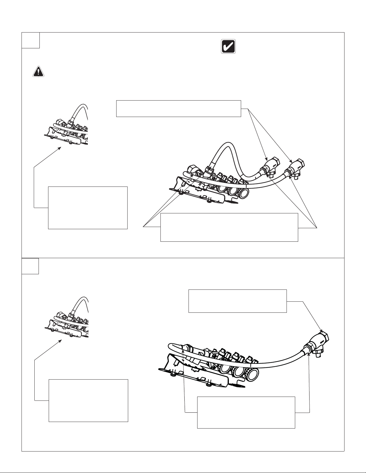
Connect the Supply — Hot and Cold Supply
WARNING:
The Vernatherm™ valve is NOT factory-preset. Upon installation, the valve temperature must be checked and
adjusted to assure delivery of safe water temperature. Water in excess of 110°F (43°C) may cause scalding.
Using a thread sealer, thread the stop/check
B
valves onto the hot and cold wall stub-outs.
Loosen but do not remove
the two mounting screws
holding the valve bracket
to the frame.
A
Slide the valve bracket up
and lift it from the frame.
Connect one end of each hose to the Vernatherm™
valve (one on the hot side, one on the cold side).
C
Connect the other swivel end to the stop/check
valves.
The letter “H” on the Vernatherm™ Mixing
Valve indicates hot water supply inlet.
4b
Connect the Supply — Single Tempered Supply
Loosen but do not remove
the two mounting screws
holding the valve bracket
to the frame.
A
Slide the valve bracket up
and lift it from the frame.
Using a thread sealer, thread
the stop/check valve onto the
B
tempered wall stub-out.
Connect one end of flexible hose
to the tempered line adapter.
C
Connect the other swivel end to
the stop/check valve.
6 12/10/07 Bradley Corporation • 215-1323 Rev. P; EN 07-814
Installation MG-3/AST4
5
6
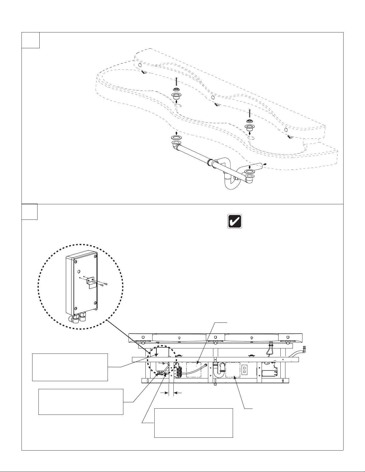
Install the Drains
Connect Optional Electric Tankless Water Heater
To Drain
Stub-Out
240/208 or 277 voltage is required for
electric tankless water heater. Refer
to the installation manual provided
with the water heater for further
installation information.
Optional Electrical Box location
Hang water heater on
rear frame member to
A
the right of the vertical
frame member.
Connect the 1/2" flexible
hose from the hot water
C
outlet to the supply inlet on
the valve assembly.
B
2" (51mm)
REF. ONLY
Connect the 1/2" flexible
hose from the cold water
supply stub-out to the hot
water heater inlet.
Recommended Electrical
Box location
Bradley Corporation • 215-1323 Rev. P; EN 07-814 12/10/07 7
MG-3/AST4 Installation
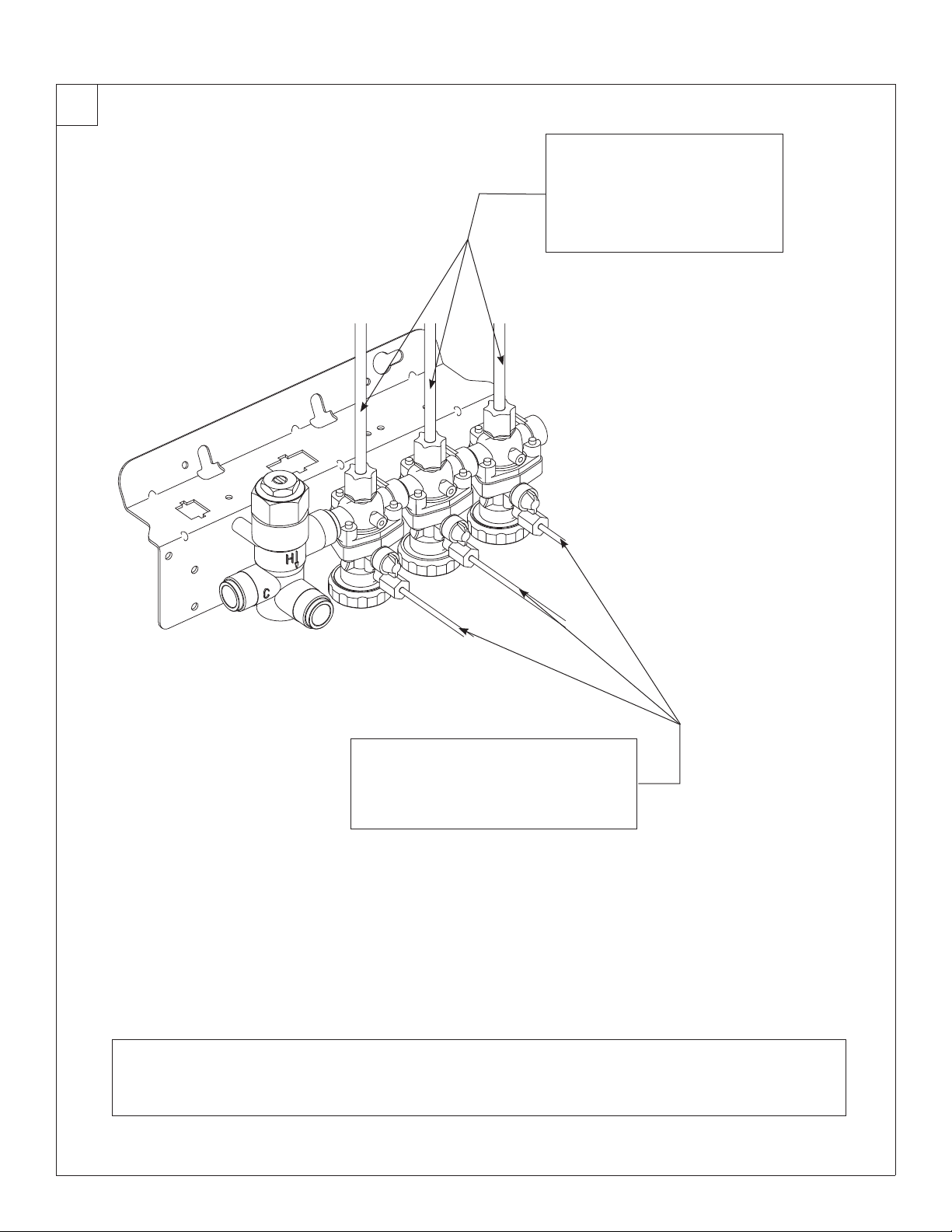
7
Connect Supply Tubing
Loosen the compression nuts.
Push the sprayhead supply
tubes firmly into the tube
connectors until they are fully
A
seated.
Tighten the compression nuts
by hand.
Loosen the compression nuts.
Push the matching color 1/8" tubes
firmly into the tube connectors until
B
they are fully seated.
Tighten the compression nuts by hand.
Reinstall the bracket. Turn on the water supply to the Express® and check for leaks.
Push the operating buttons of each station until all the air is purged from the lines and water is flowing smoothly.
C
Reinstall the ccess panel.
8 12/10/07 Bradley Corporation • 215-1323 Rev. P; EN 07-814
Installation MG-3/AST4
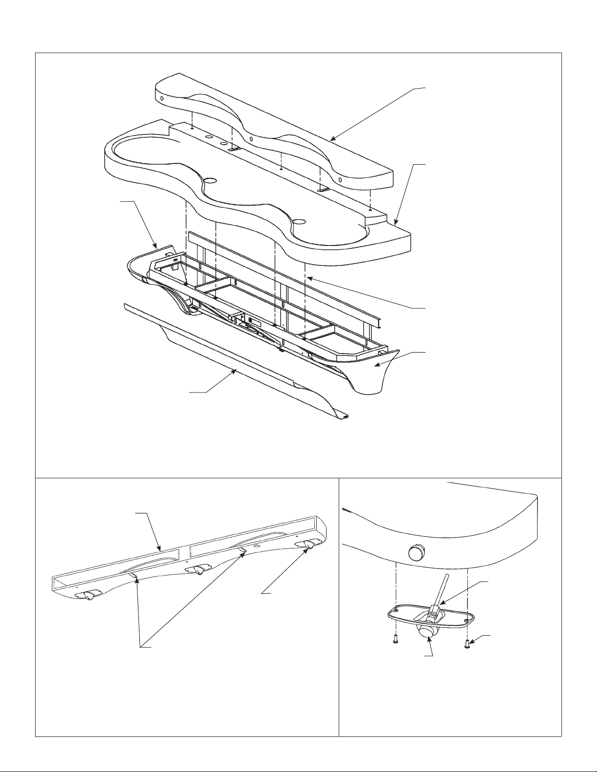
Components
SPRAYHEAD BODY
(PART NUMBER VARIES WITH
COLOR OF UNIT. CONTACT
YOUR LOCAL BRADLEY REP.
FOR ASSISTANCE).
BOWL
(PART NUMBER VARIES WITH
END CAP (LEFT)
(PART NUMBER
VARIES WITH
COLOR OF UNIT.
CONTACT YOUR
LOCAL BRADLEY
REP. FOR
ASSISTANCE).
COLOR OF UNIT. CONTACT
YOUR LOCAL BRADLEY REP.
FOR ASSISTANCE).
SPRAYHEAD
MOUNTING BOLTS (3)
STAINLESS STEEL
ACCESS PANEL
SPRAYHEAD BODY
186-1263.
MOUNTING LOCATION
TO BOWL (5) PLACES
SPRAYHEAD
AERATOR
ASSEMBLY
S05-166
HOUSING-FLOW
CONTROL S05-142
END CAP (RIGHT)
(PART NUMBER VARIES WITH
COLOR OF UNIT. CONTACT
YOUR LOCAL BRADLEY REP.
FOR ASSISTANCE).
CONNECTOR 1/4"
TUBE 145-089
SCREW ALLEN
SOCKET #10-24
160-138
Bradley Corporation • 215-1323 Rev. P; EN 07-814 12/10/07 9
 Loading...