

Page 1
Installation
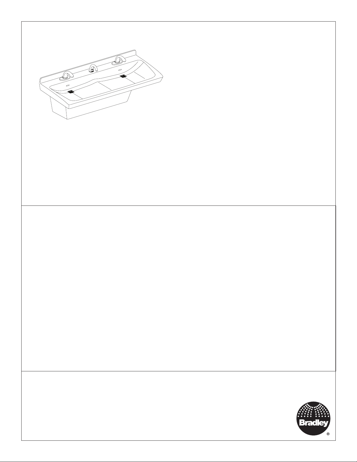
ELX-2
Express® Lavatory System – ELX-Series
®
Système lave-mains Express
– Série ELX
Sistema de lavabo Express
®
– Serie ELX
WARNING
Turn OFF electrical power to the electrical outlets, then unplug all electrical units prior to installation.
Electrical power MUST remain off until installation is complete.
Installer’s hardware must be appropriate for wall construction. Wall anchors must have a minimum pull-out
rating of 1,000 lbs.
NOTICE
Make sure that all water supply lines have been flushed and then completely turned off before beginning
installation. Debris in supply lines can cause valves to malfunction.
IMPORTANT
Read this entire installation manual to ensure proper installation. When finished with the installation, file
this manual with the owner or maintenance department. Compliance and conformity to local codes and
ordinances is the responsibility of the installer. Product warranties may be found under “Products” on our
Web site at bradleycorp.com.
Separate parts from packaging and make sure all parts are accounted for before discarding any packaging
material. If any parts are missing, do not begin installation until you obtain the missing parts.
For standard height mounting, do not exceed the recommended 33.5" distance from the fixture rim to the
finished floor.
215-1807 Rev. C; ECN 16-08-008
© 2016 Bradley
Page 1 of 37 5/20/2016
Menomonee Falls, WI 53052 USA
800 BRADLEY (800 272 3539)
P.O. Box 309
+1 262 251 6000
bradleycorp.com
Page 2

ELX-2 Installation
Table of Contents
Components ................................................................................................................................................................................ 3–4
Supplies Required ........................................................................................................................................................................... 5
Dimensions .................................................................................................................................................................................. 5–6
Rough-Ins ........................................................................................................................................................................................ 7
Frame Mounting ...............................................................................................................................................................................8
Faucet Box and Valve Mounting ...................................................................................................................................................... 9
Overflow Plug Assembly .................................................................................................................................................................. 9
Drain Assembly ............................................................................................................................................................................. 10
Faucets and Optional Soap Valve .................................................................................................................................................10
Bowl Mounting ............................................................................................................................................................................... 11
Strainer and P-trap ........................................................................................................................................................................ 11
Adjust Temperature ........................................................................................................................................................................ 12
Trap Cover ..................................................................................................................................................................................... 12
Cleaning and Maintenance ............................................................................................................................................................ 13
Table des matières
Composants .............................................................................................................................................................................15-16
Fournitures requises ...................................................................................................................................................................... 17
Dimensions ............................................................................................................................................................................... 17-18
Raccordements ............................................................................................................................................................................. 19
Montage du bâti ............................................................................................................................................................................. 20
Fixation du boîtier de batterie et de la vanne ................................................................................................................................ 21
Assemblage du bouchon de trop-plein .......................................................................................................................................... 21
Assemblage de l’écoulement ......................................................................................................................................................... 22
Robinets et vanne à savon en option ............................................................................................................................................ 22
Fixation de la vasque .................................................................................................................................................................... 23
Tamis et siphon en P ..................................................................................................................................................................... 23
Fair couler l'eau pour régler la température .................................................................................................................................. 24
Couvre-siphon ............................................................................................................................................................................... 24
Nettoyage et entretien ................................................................................................................................................................... 25
Contenido
Componentes ...........................................................................................................................................................................27-28
Materiales necesarios ................................................................................................................................................................... 29
Dimensiones ............................................................................................................................................................................ 29–30
Colocación de las tuberías empotradas ........................................................................................................................................ 31
Montaje de la estructura ................................................................................................................................................................ 32
Montaje de la caja de la llave y de la válvula ................................................................................................................................33
Conjunto de tapón contra desbordes ............................................................................................................................................ 33
Conjunto de desagüe .................................................................................................................................................................... 34
Llaves y válvula de jabón opcional ................................................................................................................................................ 34
Montaje de la palangana ............................................................................................................................................................... 35
Filtro y sifón en P .......................................................................................................................................................................... 35
Adjuste la temperatura .................................................................................................................................................................. 36
Cubierta del sifón .......................................................................................................................................................................... 36
Limpieza y mantenimiento ............................................................................................................................................................. 37
2 5/20/2016 Bradley • 215-1807 Rev. C; ECN 16-08-008
Page 3
Installation ELX-2
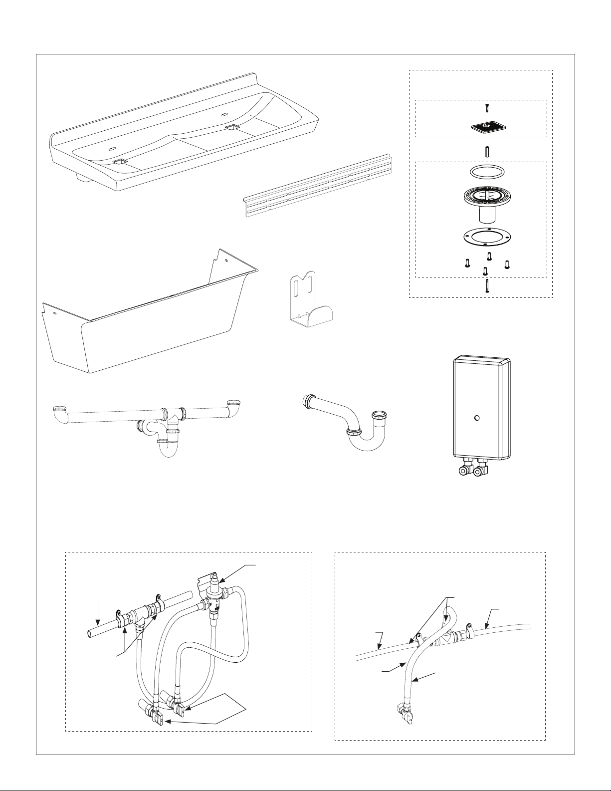
Components
Bowl (shown with coved backsplash)
Contact your Bradley Representative for
color options
Access Panel
(186-1899)
Wall Bracket
(140-1128)
Trap Cover Bracket
(140-1129)
Complete Drain Prepack
(S45-2811)
Prepack
(S45-2810)
*Standoff, Hex,
SS #6-32 x 1"
Drain
Adapter
Prepack
(S45-2480)
*Included in
Prepack S45-2778
*Screw
Strainer
O-Ring
(125-111)
Drain
Adapter
Packing
Washer
#10-24
Screw
*Screw #6-32
x 1-1/4" Pan
Combined Rough-In Option
Chrome Waste Assembly (S45-2654)
Plastic Waste Assembly (S45-2662)
TMV Supply
Connections
Plastic Hose
Supply
Fittings
(S45-2510)
TMV Valve
(½" NPTM
Outlet) (S45-
2701)
Hose Prepack
(S45-2730)
Individual Rough-In Option
Chrome P-trap (S29-094)
Plastic P-trap (269-1697)
Tempered Supply
Connections
Plastic
Hose
Stainless
Steel
Hose
Optional Tankless Water Heater
(269-1767 - EX95TMLB, 240/208 volts)
(269-1768 - EX100TMLB, 277 volts)
Supply Fittings
(S45-2511)
Plastic Hose
Hose Prepack
(S45-2731)
Bradley • 215-1807 Rev. C; ECN 16-08-008 5/20/2016 3
Page 4
ELX-2 Installation
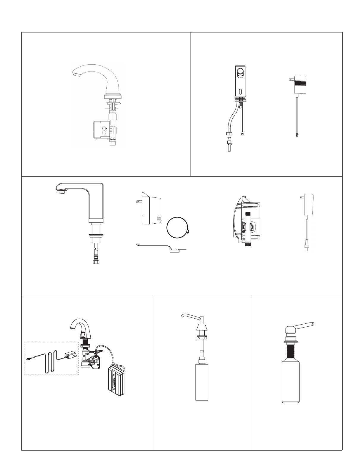
Components
Plug-In Transformer
1200 Series Capacitive Faucet*
(S53-315)
*Adapter S45-2874 included with faucet
IR-DCD Faucet**
(S53-336)
**Adapter S45-2872 included with faucet
Option (PT) for IR-
DCD Faucet
(S53-337)
CAP-DCA Faucet
Optional
Transformer
6315-000000 Soap Dispenser
(S53-334)
Plug-in transformer option (PT) includes
Transformer (S53-338), Adapter (S53-339), and
Grounding Kit (S53-349) for CAP-DCA Faucets
6324-68 Soap Dispenser 6334 Soap Dispenser
Battery Box for
CAP-DCA Faucets
Plug-In Transformer
Option (PT)
for S53-315 Faucet
(153-443)
4 5/20/2016 Bradley • 215-1807 Rev. C; ECN 16-08-008
Page 5
Installation ELX-2
Supplies Required
• (6) ³⁄₈" fasteners and wall anchors (minimum pull-out rating of 1,000 lbs.)
• (4) ¼" fasteners and wall anchors (minimum pull-out rating of 100 lbs.)
• ½" hot/cold or tempered stub-out(s)
• 1½" NPT drain stub-out(s)
• OPTIONAL: (2) 110 volt GFCI protected electrical outlets for 100–120 VAC plug-in transformers
• OPTIONAL WATER HEATER: Electrical supply and fittings per local code
• Screen filter(s) as needed, if not included with faucet(s)
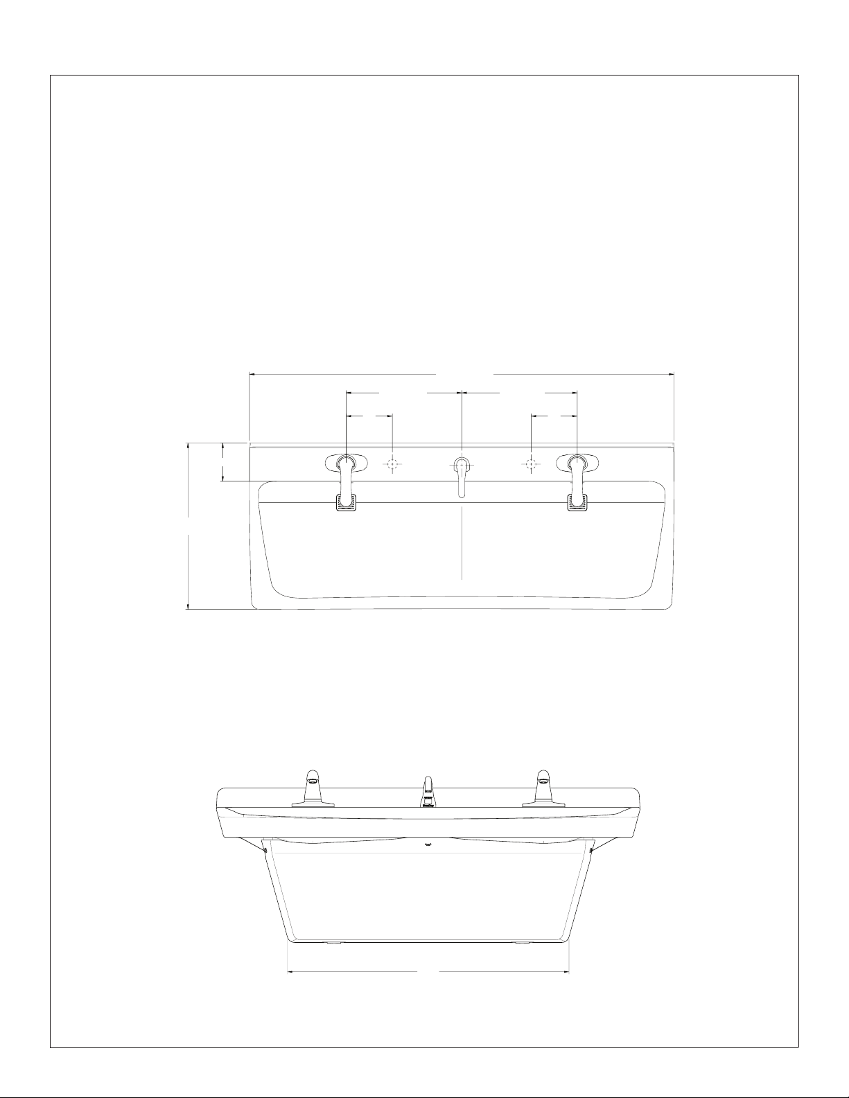
Dimensions
Top View (shown with shared soap)
55"
(1397mm)
15"
(381mm)
6"
(152mm)
15"
(381mm)
(152mm)
6"
Front View
21⁵⁄₈"
(549mm)
5" (165mm)
A
A = Personal soap location
A
36³⁄₄"
(933mm)
Bradley • 215-1807 Rev. C; ECN 16-08-008 5/20/2016 5
Page 6
ELX-2 Installation
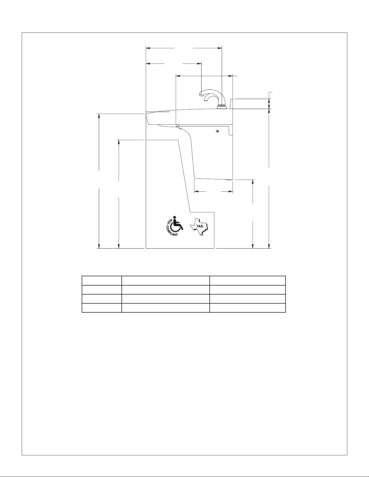
Dimensions – Side View
33½"*
(851mm)
27"*
(686mm)
18⁷⁄₈"
(480mm)
13¾"
(349mm)
14¹⁄₈"
(359mm)
2½"
(64mm)
34½"
(876mm)
9⁵⁄₈"
(244mm)
17¹⁄₈"*
(435mm)
Rim Height Vertical Height Adjustments Fixture Style
33½" No Adjustment ADA Standard & TAS
30½" *Subtract 3" ADA Juvenile & TAS
26" *Subtract 7½" Junior
6 5/20/2016 Bradley • 215-1807 Rev. C; ECN 16-08-008
Page 7

Installation ELX-2
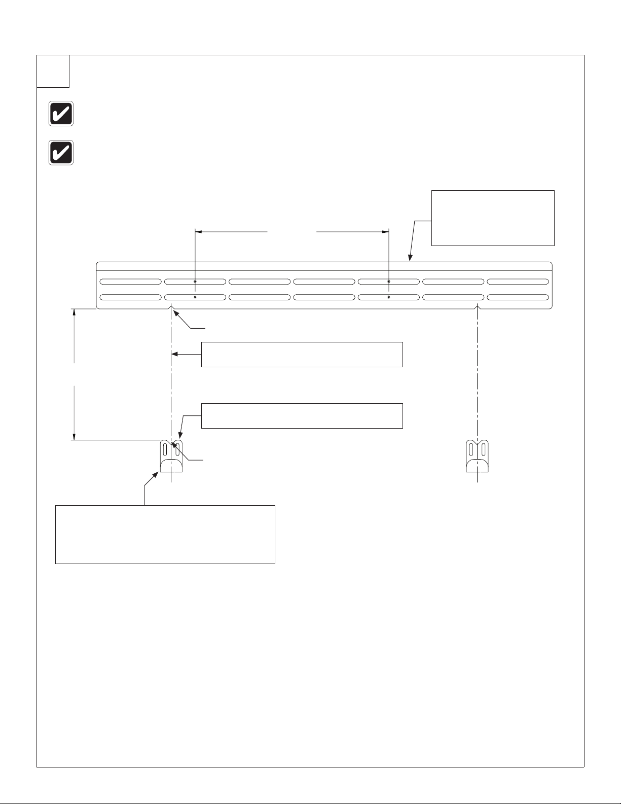
Structural Rough-Ins
Mounting for standard ADA and TAS height shown.
Areas highlighted in gray require sufficient backing
compliant with local building codes.
Wall Bracket
A
33½"
(851mm)
Ref. Rim
Height
(813mm)
32"
(762mm)
bracket to
finished
26³⁄₈"
C
(670mm)
30"
bottom
of wall
floor
10½"
(267mm)
12¼"
(311mm)
19¾"
(502mm)
24"
(610mm)
36½" (927mm)
C
L
(311mm)
12¼"
(502mm)
BB
19¾"
24"
(610mm)
Secure bracket to wall using min.
(2) ³⁄₈" anchor bolts to the left of
C/L and min. (2) ³⁄₈" anchor bolts
to the right of C/L. The (2) anchor
bolts to the right of C/L must be
min. 16" apart from the anchor bolts
to the left of C/L. When mounting
is complete, check to ensure the
bracket is level.
A
C
32"
(813mm)
26½"
(673mm)
Trap Cover Bracket
(2x)
CODE DESCRIPTION QTY.
A
Install (1) ³⁄₈" wall anchor with a minimum pull-out force of 1,000 lbs. per local codes at locations shown
B Install (2) wall anchors per bracket with a minimum pull-out force of 100 lbs. per local codes at locations shown 4
C Provide structural backing compliant with local building codes. 2
2
Rim Height Vertical Height Adjustments Fixture Style
33½" No Adjustment Standard, ADA & TAS
30½" Subtract 3" Juvenile, ADA & TAS
26" Subtract 7½" Junior
Bradley • 215-1807 Rev. C; ECN 16-08-008 5/20/2016 7
Page 8

ELX-2 Installation
Plumbing and Electrical Rough-Ins
Mounting for Standard, ADA and TAS height shown.
E
33½"
(851mm)
Rim
Height
27¼ - 28¼"
(692 -
718mm)
22" - 27"
(559 -
686mm)
20" - 23"
584mm)
23¾ - 24¾"
(603 -
629mm)
(508 -
18" - 21"
(457 -
533mm)
17"
(432mm)
A
P
2" - 3"
(51 - 76mm)
4" - 5"
(102 - 127mm)
13½" - 16½"
(343 - 419mm)
E
S
H
B
C
P
2" - 3"
(51 - 76mm)
4" - 5"
(102 - 127mm)
13½" - 16½"
(343 - 419mm)
A
W
Trap Cover
Perimeter
CODE DESCRIPTION QTY.
A 1½" NPT Drain, Stub-out 2" from wall, individual waste option 2
B 1½" NPT Drain, Stub-out 2" from wall, combined waste option (waste arms to be cut in field) 1
H,C
½" Nominal (⁵⁄₈" O.D. Comp.) Hot/Cold supplies, Stub-out 2" from wall
E 110V GFI protected electrical outlet (AC faucet and soap only) 2
S Outline of shared soap container (if selected) 1
P Outline of personal soap container (if selected) 2
W
Water Heater Option: Rough-in electrical supply per local code (240/208v or 277v depending on model). Water
heater will be wall mounted where space allows. See water heater instructions for more information.
1
1
8 5/20/2016 Bradley • 215-1807 Rev. C; ECN 16-08-008
Page 9
Installation ELX-2
1
Bracket Mounting
Typical installation is shown. It may be necessary to repair the wall
after mounting. The fixture may not cover all of the wall modifications.
Mounting height per structural rough-in dimensions.
16"
(406mm)
min.
Locating Notch
Using the location notches on the wall bracket,
B
draw a vertical line down at least 12".
10½"
(267mm)
Install wall bracket to wall
per structural rough-in
dimensions. Check to
A
ensure the bracket is
level. Example anchor
locations shown.
C
Locating Notch
Install trap cover bracket by lining up the locating
notch on the trap cover bracket to the vertical line.
D
Line up the top of the trap cover bracket to the
horizontal line. Secure the brackets to the wall
anchors using fasteners per the structural rough-in
requirement (supplied by installer). (2x)
Measure down 10½" from the bottom of the
wall bracket and draw a horizontal line.
Bradley • 215-1807 Rev. C; ECN 16-08-008 5/20/2016 9
Page 10
ELX-2 Installation
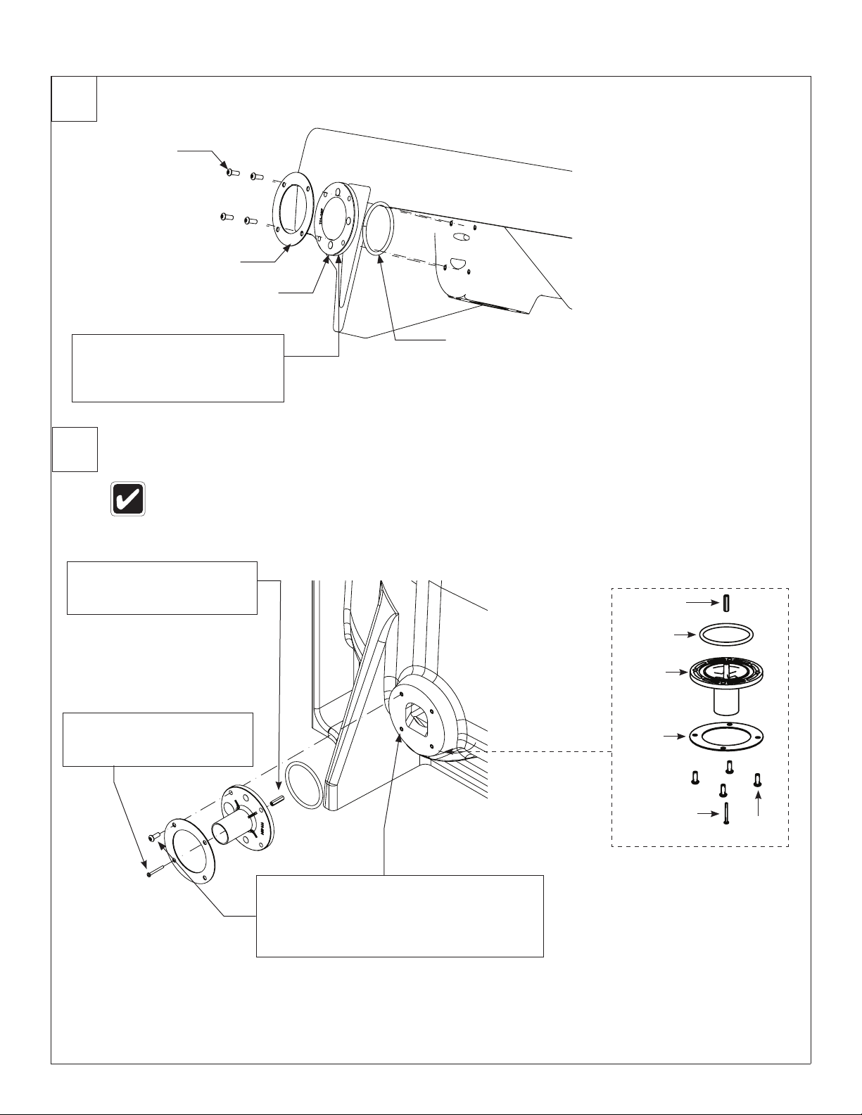
2
3
Overflow Plate Assembly
P10-225
142-135
Overflow plate
Assemble overflow drain plate
to basin as shown. Ensure the
A
screws compress the overflow
plate evenly onto the basin.
Drain Assembly
For ease of drain installation, lay the bowl on its back.
(125-111)
Overflow Plate Prepack
(S45-2812)
Thread the standoff onto
the now fully engaged
B
screw.
Thread screw into drain
adapter until it becomes
A
fully engaged.
Assemble the remaining components as
shown and thread the four screws through
the drain adapter and into the basin inserts.
C
Ensure the screws compress the drain
adapter evenly onto the basin.
Standoff, Hex
SS #6-32 x 1"
O-Ring
Drain
Adapter
Packing
Washer
#6-32 x 1-1/4"
Screw
#10-24
Screw
10 5/20/2016 Bradley • 215-1807 Rev. C; ECN 16-08-008
Page 11
Installation ELX-2
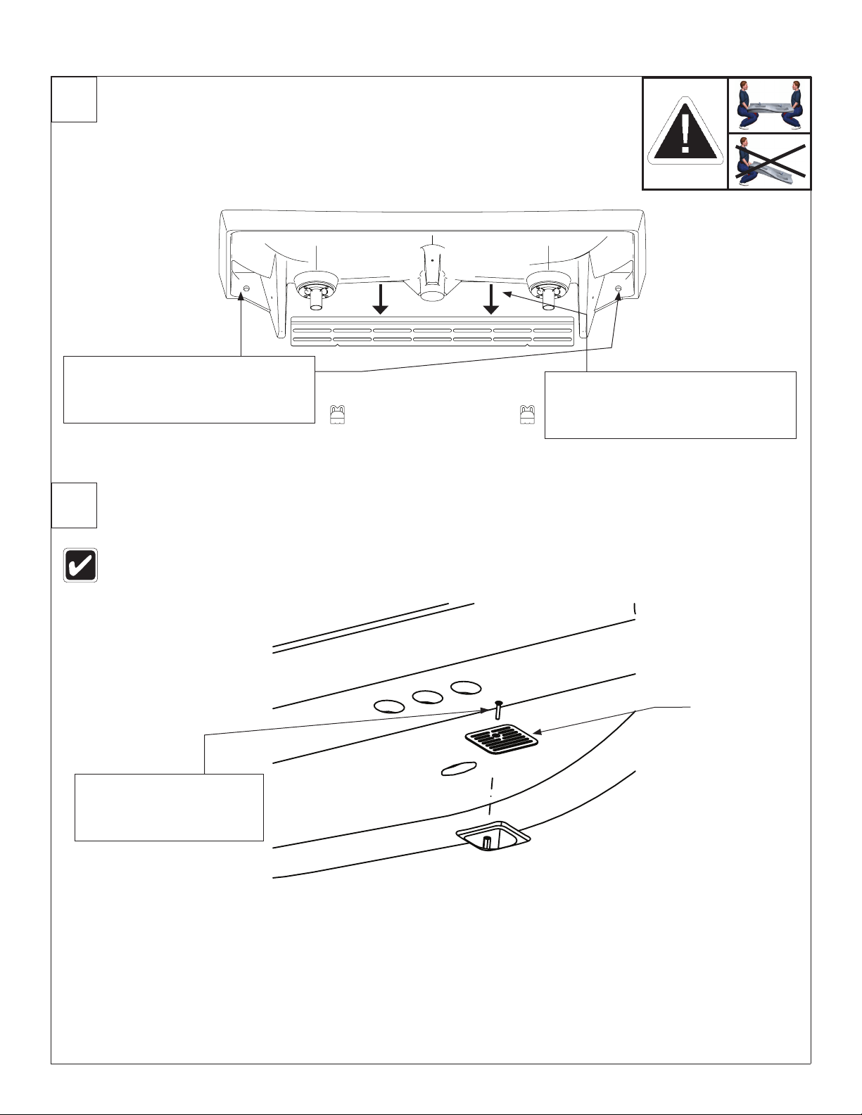
4
5
Bowl Mounting (to Frame and Wall)
WARNING! Ensure bowl is level and completely seated in the wall bracket.
Secure the bowl to the wall anchors
using fasteners per the structural
B
rough-in requirement (supplied by
installer).
A
Strainer and P-Trap
Position bowl above wall bracket.
Press firmly on the back of the bowl
to seat the bowl flange into the wall
bracket lip. Ensure bowl is level.
Ensure not to overtighten the strainer screw.
Thread the strainer screw
through the strainer and
A
into the stand off on the
drain adapter.
Strainer
Bradley • 215-1807 Rev. C; ECN 16-08-008 5/20/2016 11
Page 12
ELX-2 Installation
6
7
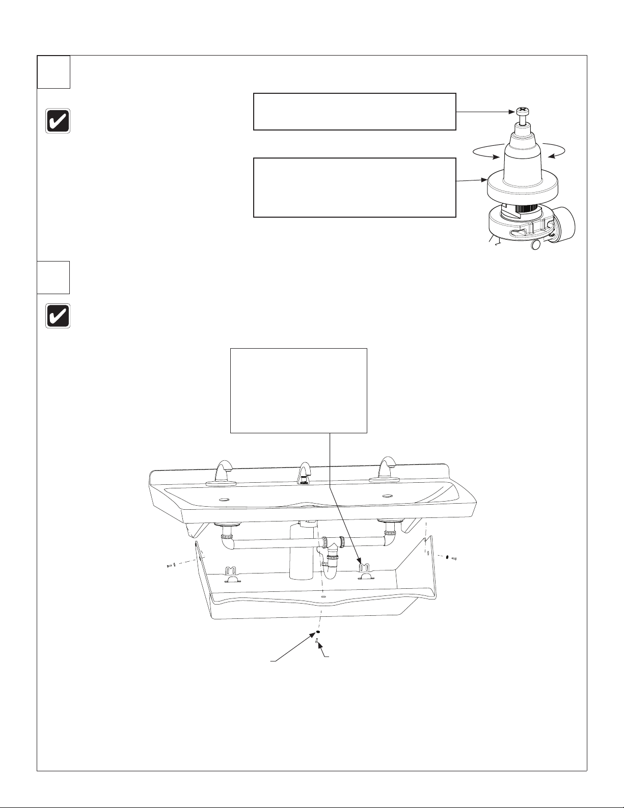
Adjust Temperature with Water Running
Loosen Cap Screw about 1/4" (4-6
This valve is NOT factory preset.
Upon installation, the temperature
of this valve must be checked and
adjusted to ensure delivery of a
safe water temperature. Water
in excess of 110°F (43°C) may
cause scalding.
turns) and lift up cover (do not
A
remove).
Using cover, turn cartridge gently until
desired water temperature is reached.
B
Do not turn past stops as this may
damage unit. Push cover down and
tighten screw.
Trap Cover
Make all connections before installing trap cover. Combined
waste arms to be cut in field to accommodate rough in location.
Hang the trap cover onto
the trap cover brackets as
shown, then secure the
A
trap cover with the screws
and finishing washers
provided, starting with the
left or right side first.
H
C
Finishing
Washer
(142-002CA)
12 5/20/2016 Bradley • 215-1807 Rev. C; ECN 16-08-008
#10-24 Flat Head Screw
(160-520)
Page 13

Installation ELX-2
Cleaning and Maintenance for Terreon
Material Description: Terreon is a densified solid surface material composed of polyester resin and is resistant to chemicals,
stains, burns and impact. Surface damage can be easily repaired with everyday cleansers or fine grit abrasives.
Routine Cleaning: Clean daily or as often as conditions require using a standard commercial or household cleaner such as
Formula 409® or Windex®.
®
Stubborn Stains: Remove tough stains with Ajax
circular motion with 240 grit wet/dry sandpaper. The finish can be renewed with a maroon Scotch-Brite pad.
, Comet®, or Soft-Scrub® and a green Scotch-Brite® pad or lightly sand in a
®
Special Situations for Terreon Material
Scratches: Remove scratches with a green Scotch-Brite pad. The finish can then be renewed with a maroon Scotch-Brite pad,
followed by a white Scotch-Brite pad or 30-micron sandpaper.
Hard Water Deposits: Remove hard water deposits with a mild solution of vinegar and water. Always rinse the unit thoroughly
after cleaning.
Restoring the surface: Use Hope’s® Solid Surface cleaner and polish to refresh and protect the Terreon Solid Surface material.
Bradley recommends additional care and maintenance for the darker colored Terreon. For complete instructions on this additional
maintenance, visit bradleycorp.com.
NOTICE Do not use strong acid or alkaline chemicals and cleansers to clean Terreon. If these chemicals
come in contact with the surface, wipe them off immediately and rinse with soapy water. Avoid contact with
harsh chemicals such as paint remover, bleach, acetone, etc. Avoid contact with hot pans and objects.
Repair Kits: Terreon repair kits are available. Contact your Bradley representative or distributor for part numbers and pricing.
Repair kits are made to order and have a shelf life of 30 days.
Terreon® is a unique, cast solid surface material. Aggregate flow and distribution as well as shades of color can
vary from product to product creating natural characteristics.
Cleaning and Maintenance for Stainless Steel
Material Description: Stainless steel is extremely durable, and maintenance is simple and inexpensive. Proper care, particularly
under corrosive conditions, is essential. Always start with the simplest solution and work your way toward the more complicated.
Routine cleaning: Daily or as often as needed use a solution of warm water and soap, detergent, or ammonia. Apply the
cleaning solution per the manufacturer's instructions and always use a soft cloth or sponge to avoid damaging the finish.
Stubborn Stains: To remove stains from stainless steel use a stainless steel cleaner and polish such as Ball® stainless steel
cleaner or a soft abrasive. Always follow the manufacturer's instructions and apply in the same direction as the polish lines.
NOTICE Never use ordinary steel wool or steel brushes on stainless steel. Always use stainless steel wool
or stainless steel brushes.
Fingerprints and Smears: To remove fingerprints or smears use a high quality stainless steel cleaner and polish in accordance
with the manufacturer's instructions. Many of these products leave a protective coating that helps prevent future smears and
fingerprints.
Grease and Oil: To remove grease and oil use a quality commercial detergent or caustic cleaner. Apply in accordance to the
manufacturer's instructions and in the direction of the polish lines.
Precautions: Avoid prolonged contact with chlorides (bleaches, salts), bromides (sanitizing agents), thiocyanates (pesticides,
photography chemicals, and some foods), and iodides on stainless steel equipment, especially if acid conditions exist.
NOTICE Do not permit salty solutions to evaporate and dry on stainless steel.
The appearance of rust streaks on stainless steel leads to the belief that the stainless steel is rusting. Look for the actual source
of the rust in some iron or steel particles which may be touching, but not actually a part of the stainless steel structure.
NOTICE Strongly acidic or caustic cleaners may attack the steel causing a reddish film to appear. The use of
these cleaners should be avoided.
Bradley • 215-1807 Rev. C; ECN 16-08-008 5/20/2016 13
Page 14

ELX-2 Installation
AVERTISSEMENT
Couper l’alimentation électrique des prises de courant, puis débrancher tous les appareils électriques avant
de procéder à l’installation. L’alimentation électrique doit IMPÉRATIVEMENT être coupée jusqu’à la fin de
l’installation.
La visserie de l’installateur doit être adaptée à la nature du mur. Les ancrages muraux doivent avoir une
résistance nominale à l’arrachement d’au moins 1 000 lb (4,45 kN).
AVIS
S’assurer que toutes les conduites d’arrivée d’eau ont été purgées puis correctement fermées avant de
commencer l’installation. La présence de débris dans les conduites peut causer un mauvais fonctionnement
des vannes.
IMPORTANT
Veiller à lire ce manuel en entier pour assurer une installation correcte. Lorsque l’installation est terminée,
remettre ce manuel au propriétaire ou au service d’entretien. La mise en conformité et le respect de la
réglementation en vigueur relèvent de la responsabilité des installateurs. Les garanties de produit peuvent
être trouvées sous « Products » sur notre site Web à www.bradleycorp.com
Déballer les pièces et s’assurer qu’elles sont toutes présentes avant de jeter les emballages. Le cas échéant,
ne pas commencer l’installation avant d’avoir obtenu toutes les pièces manquantes.
Pour les poses de hauteur standard, ne pas dépasser la distance conseillée de 851mm (33,5") entre le rebord
de l’appareil sanitaire et le sol fini.
14 5/20/2016 Bradley • 215-1807 Rev. C; ECN 16-08-008
Page 15

Installation ELX-2
Composants
Vasque (représentée avec un dosseret à base arrondie)
Se renseigner sur le choix de couleurs auprès du
représentant Bradley.
Panneau d’accès
(186-1899)
Support mural
(140-1128)
Support de couvre-
siphon (140-1129)
Trousse d’écoulement
complète (S45-2811)
Trousse
(S45-2810)
Trousse
adaptateur
d’écoulement
(S45-2480)
* Inclus dans la
trousse S45-2778
* Vis
Tamis
* Entretoise hexa,
inox #6-32 x 1"
Joint
torique
(125-111)
Adaptateur
d’écoulement
Bague
d’étanchéité
Vis n°
10-24
* Vis cylindrique
bombée
n° 6-32 x 1-1/4"
Option raccordements combinés
Tuyauterie d’évacuation chromée (S45-2654)
Tuyauterie d’évacuation en plastique (S45-2662)
Raccordements
d’alimentation TMV
Tuyau en plastique
Raccords
d’alimentation
(S45-2710)
Siphon en P en plastique (269-1697)
Vanne TMV
(Sortie 1/2"
NPTM)
(S45-2701)
Trousse tuyaux
(S45-2730)
Option raccordements séparés
Siphon en P chromé (S29-094)
Raccordements
d’alimentation tempérée
Tuyau en
plastique
Tuyau
en acier
inoxydable
Chauffe-eau instantané en option
(269-1767 - EX95TMLB, 240/208 volts)
(269-1768 - EX100TMLB, 277 volts)
Raccords
d’alimentation
(S45-2511)
Tuyau en
plastique
Trousse tuyaux
(S45-2731)
Bradley • 215-1807 Rev. C; ECN 16-08-008 5/20/2016 15
Page 16

ELX-2 Installation
Composants
L’option à transformateur
à fiche (PT) pour robinet
Robinet à détecteur capacitif série 1200*
(S53-315)
*l’adaptateur (S45-2874) fourni avec le robinet
Robinet IR-DCD **
(S53-336)
**l’adaptateur (S45-2872) fourni avec le robinet
IR-DCD
(S53-337)
Robinet CAP-DCA
Transformateur
en option
Distributeur de savon 6315-000000
(S53-334)
L’option à transformateur à fiche (PT) comprend
le transformateur (S53-338), l’adaptateur
(S53-339) et le nécessaire de mise à la terre
(S53-349) pour les robinets CAP-DCA
Distributeur de savon 6324-68 Distributeur de savon 6334
Boîtier de batterie pour
robinets CAP-DCA
L’option à transformateur
à fiche (PT) pour robinet
S53-315
(153-443)
16 5/20/2016 Bradley • 215-1807 Rev. C; ECN 16-08-008
Page 17

Installation ELX-2
Fournitures requises
• Six (6) chevilles d’ancrage et vis de 3/8" (résistance nominale à l’arrachement d’au moins 4,45 kN [1000 lb])
• Quatre (4) chevilles d’ancrage et vis de 1/4" (résistance nominale à l’arrachement d’au moins 0,44 kN [100 lb])
• Tubulure(s) 1/2" chaud/froid ou tempéré
• Tubulure(s) d’écoulement 1-1/2" NPT
• EN OPTION : Deux (2) prises électriques 110 V à disjoncteur à protection DDFT (GFCI) pour transformateur à fiche
100–120 Vca
• CHAUFFE-EAU EN OPTION : Alimentation et accessoires électriques selon le code de l’électricité local
• Filtre(s) à tamis selon les besoins, si non fourni(s) avec le(s) robinet(s)
Dimensions
Vue de dessus (représenté avec distributeurs de savon communs)
55"
(1397mm)
15"
(381mm)
6"
(152mm)
15"
(381mm)
6"
(152mm)
Vue de face
21⁵⁄₈"
(549mm)
5" (165mm)
A
A = emplacement des distributeurs de savon personnels
A
36¾"
(933mm)
Bradley • 215-1807 Rev. C; ECN 16-08-008 5/20/2016 17
Page 18

ELX-2 Installation
Dimensions — Vue de côté
18⁷⁄₈"
(480mm)
13¾"
(349mm)
14¹⁄₈"
(359mm)
2½"
(64mm)
33½"*
(851mm)
27"*
(686mm)
9⁵⁄₈"
(244mm)
(435mm)
34½"
(876mm)
17¹⁄₈"*
Hauteur du rebord Ajustements de la hauteur Type d’appareil
851mm (33-1/2") Pas d’ajustement ADA standard & TAS
775mm (30-1/2") *Retrancher 76mm (3") ADA enfants & TAS
660mm (26") *Retrancher 191mm (7-1/2") Junior
18 5/20/2016 Bradley • 215-1807 Rev. C; ECN 16-08-008
Page 19

Installation ELX-2
Raccordements structurels
Montage représenté pour une hauteur standard ADA et TAS.
Les zones grisées nécessitent un renfort suffisant
conforme au code du bâtiment en vigueur.
36½" (927mm)
33½" (851mm)
Hauteur du
rebord de réf.
(813mm)
32"
(762mm)
du bas du
support
mural au
sol fini
Support mural
26³⁄₈"
(670mm)
30"
A
10½"
C
(267mm)
12¼"
(311mm)
19¾"
(502mm)
24"
(610mm)
C
L
12¼"
(311mm)
(502mm)
BB
19¾"
24" (610mm)
Fixer le support au mur à l’aide de deux
(2) boulons d’ancrage minimum de ³⁄₈" à
gauche de l’axe central (CL) et de deux
(2) boulons d’ancrage minimum de ³⁄₈" à
droite de cet axe. Les deux (2) boulons
d’ancrage situés à droite de l’axe central
doivent se trouver à une distance
d’au moins 16" (406mm) des boulons
d’ancrage situés à gauche de l’axe. Une
fois le montage terminé, vérifier que le
support est de niveau.
A
C
32"
(813mm)
26½"
(673mm)
Support de couvre-
siphon (2x)
CODE DESCRIPTION QTÉ
A
B
Poser une (1) cheville d’ancrage
conformément aux normes en vigueur, aux emplacements indiqués.
Poser deux (2) chevilles d’ancrage d’une résistance minimale à l’arrachement de 0,44 kN (100 lb),
conformément aux normes en vigueur, aux emplacements indiqués.
C Poser un renfort suffisant conforme au code du bâtiment en vigueur. 2
³⁄₈" d’une résistance minimale à l’arrachement de 4,45 kN (1000 lb),
2
4
Hauteur du rebord Ajustements de la hauteur Type d’appareil
851mm (33-1/2") Pas d’ajustement Standard, ADA & TAS
775mm (30-1/2") *Retrancher 76mm (3") Enfants, ADA & TAS
660mm (26") *Retrancher 191mm (7-1/2") Junior
Bradley • 215-1807 Rev. C; ECN 16-08-008 5/20/2016 19
Page 20

ELX-2 Installation
Plomberie et raccordements électriques
Montage représenté pour une hauteur standard, ADA et TAS.
E
A
W
Périmètre
du couvre-
siphon
33½"
(851mm)
Hauteur
du rebord
27¼ - 28¼"
(692 -
718mm)
22" - 27"
(559 -
686mm)
23¾ - 24¾"
(603 -
629mm)
20" - 23"
(508 -
584mm)
18" - 21"
(457 -
533mm)
17"
(432mm)
A
P
2" - 3"
(51 - 76mm)
4" - 5"
(102 - 127mm)
13½" - 16½"
(343 - 419mm)
E
S
H
B
C
P
2" - 3"
(51 - 76mm)
4" - 5"
(102 - 127mm)
13½" - 16½"
(343 - 419mm)
CODE DESCRIPTION QTÉ
A Écoulement 1½" NPT, tubulure à 51mm (2") du mur, option raccordements d’évacuation séparés 2
B
H,C
E
Écoulement 1½" NPT, tubulure à 51mm (2") du mur, option raccordements d’évacuation combinés (tuyaux
à couper sur place)
Arrivées d’eau chaude/froide de ½" nominal (comp. ⁵⁄₈" dia. ext.), tubulure à 51mm (2") du mur
Prise électrique 110 V à disjoncteur à protection DDFT (GFI) (pour robinets et distributeurs de savon
électriques uniquement)
S Contour du distributeur de savon commun (si cette option a été choisie) 1
P Contour du distributeur de savon personnel (si cette option a été choisie) 2
Chauffe-eau en option : raccorder l’alimentation électrique conformément au code de l’électricité local
W
(240/208 V ou 277 V selon le modèle). Le chauffe-eau sera fixé au mur, à un emplacement disposant d’un
espace suffisant. Voir les instructions concernant le chauffe-eau pour plus d’informations.
1
1
2
1
20 5/20/2016 Bradley • 215-1807 Rev. C; ECN 16-08-008
Page 21

Installation ELX-2
1
Montage du support
Installation typique représentée. Il peut être nécessaire de réparer le mur après la pose.
Il est possible que l’appareil ne masque pas toutes les modifications apportées au mur.
Hauteur de montage selon les dimensions spécifiées des
raccordements structurels.
16"
(406mm) min.
Encoche de positionnement
En partant des encoches de positionnement du
B
10½"
(267mm)
support mural, tracer une ligne verticale vers le
bas de 12" (305mm) au moins.
Fixer le support mural
sur le mur selon les
dimensions spécifiées des
raccordements structurels.
Vérifier que le support est
A
de niveau. Emplacement
des ancrages présenté à
titre d’exemple.
C
Encoche de positionnement
Installer le support de couvre-siphon en alignant
l’encoche de positionnement du support sur la ligne
D
verticale. Aligner le haut du support de couvresiphon sur la ligne horizontale. Fixer les supports
aux chevilles d’ancrage à l’aide de vis (fournies par
l’installateur), conformément aux exigences relatives
aux raccordements structurels. (2x)
Mesurer 10½" (267mm) vers le bas à partir
du bas du support mural, puis tracer une ligne
horizontale.
Bradley • 215-1807 Rev. C; ECN 16-08-008 5/20/2016 21
Page 22

ELX-2 Installation
2
3
Assemblage de la plaque de trop-plein
P10-225
142-135
Plaque de trop-plein
Monter la plaque de trop-plein sur
la vasque comme sur l’illustration.
A
Vérifier que les vis compriment la
plaque uniformément sur la vasque.
Assemblage de l’écoulement
Pour faciliter l’installation de l’écoulement, poser la vasque sur le dos.
(125-111)
Trousse plaque de trop-plein
(S45-2812)
Visser l’entretoise sur la vis
à présent complètement
B
engagée.
Engager la vis à fond dans
l’adaptateur d’écoulement.
A
Assembler les composants restants comme indiqué,
puis enfoncer les quatre vis à travers l’adaptateur
d’écoulement et serrer les vis dans les inserts de la
C
vasque. Vérifier que les vis compriment l’adaptateur
d’écoulement uniformément sur la vasque.
Entretoise hexa,
inox #6-32 x 1"
Joint torique
Adaptateur
d’écoulement
Bague
d’étanchéité
n° 6-32 x 1-1/4"
Vis
Vis n°
10-24
22 5/20/2016 Bradley • 215-1807 Rev. C; ECN 16-08-008
Page 23

Installation ELX-2
4
5
Fixation de la vasque (au bâti et au mur)
AVERTISSEMENT! Vérifier que la vasque est de niveau et bien en place dans le
support mural.
Fixer la vasque sur les chevilles d’ancrage
à l’aide de vis (fournies par l’installateur),
conformément aux exigences relatives
B
aux raccordements structurels.
Placer la vasque au-dessus du support
mural. Appuyer fermement sur l’arrière de
la vasque pour l’engager complètement
A
dans le support mural. Vérifier que la
vasque est de niveau.
Tamis et siphon en P
Veiller à ne pas trop serrer la vis du tamis.
Enfoncer la vis du tamis à
travers le tamis, puis serrer
la vis dans l’entretoise de
A
l’adaptateur d’écoulement.
Tamis
Bradley • 215-1807 Rev. C; ECN 16-08-008 5/20/2016 23
Page 24

ELX-2 Installation
6
7
Faire couler l’eau pour régler la température
Desserrer la vis à tête de 1/4" (6mm) environ
Cette vanne n’est PAS préréglée
à l’usine. Lors de l’installation, la
température de cette vanne doit
être contrôlée et ajustée pour
s’assurer que l’eau est fournie
à une température sans danger.
Une eau à plus de 43 °C (110 °F)
peut ébouillanter.
(4 à 6 tours) et soulever le capuchon (ne pas
A
l’enlever).
À l’aide du capuchon, tourner lentement la
cartouche jusqu’à obtenir la température d’eau
souhaitée. Pour ne pas endommager l’appareil,
B
ne pas tourner au-delà des butées. Renfoncer
le capuchon et serrer la vis.
Couvre-siphon
Effectuer tous les raccordements avant d’installer le couvre-siphon. Tuyaux d’évacuation
combinés à couper sur place en fonction de l’emplacement des raccordements.
H
C
Accrocher le couvre-siphon sur
les supports comme indiqué, puis
fixe le couvre-siphon à l’aide des
A
vis et des rondelles de finition
fournies, en commençant du côté
gauche ou du côté droit.
Rondelle de
finition
(142-002CA)
Vis à tête plate
n° 10-24 (160-520)
24 5/20/2016 Bradley • 215-1807 Rev. C; ECN 16-08-008
Page 25

Installation ELX-2
Nettoyage et entretien du Terreon
Description du matériau : Le Terreon est un matériau de surface massif densifié composé de résine de polyester et résistant aux
produits chimiques, aux taches, aux brûlures et aux chocs. Les dommages superficiels sont facilement réparables à l’aide de produits
nettoyants ordinaires ou d’abrasifs à grains fins.
Nettoyage courant : Nettoyer chaque jour ou aussi souvent que les conditions l’exigent avec un nettoyant ménager ou commercial
standard tel que Formula 409
Taches résistantes : Éliminer les taches difficiles avec Ajax
légèrement d’un mouvement circulaire avec du papier de verre pour ponçage humide/sec de grain 240. La finition peut être restaurée
avec un tampon Scotch-Brite marron.
®
ou Windex®.
®
®
, Comet® ou Soft-Scrub® et un tampon vert Scotch-Brite®, ou poncer
Situations particulières pour le Terreon
Rayures : Éliminer les rayures avec un tampon Scotch-Brite vert. La finition peut être restaurée avec un tampon Scotch-Brite marron,
suivie d’un tampon Scotch-Brite blanc ou de papier de verre de 30 microns.
Dépôts calcaires : Éliminer les dépôts calcaires avec une solution diluée de vinaigre et d’eau. Toujours rincer l’appareil avec soin après
tout nettoyage.
®
Restauration de la surface : Utiliser le produit nettoyant et lustrant pour surfaces massives de Hope
surface de Terreon. Bradley préconise un entretien et des soins supplémentaires pour les surfaces en Terreon de couleur sombre. Voir les
instructions complètes sur cet entretien supplémentaire à bradleycorp.com.
AVIS Ne pas utiliser de produits nettoyants et détergents fortement acides ou alcalins pour nettoyer le Terreon.
Si de tels produits viennent au contact de la surface, essuyer immédiatement et rincer à l’eau savonneuse. Éviter
le contact avec des substances corrosives telles que du décapant à peinture, de l’eau de Javel, de l’acétone, etc.
Éviter le contact avec des casseroles et autres objets chauds.
Trousses de réparation : Des nécessaires de réparation Terreon sont disponibles. S’adresser au représentant ou distributeur Bradley
pour connaître les numéros de références et les prix. Les trousses de réparation sont préparées sur commande et ont une durée de
conservation de 30 jours.
pour rafraîchir et protéger la
Le Terreon® est un matériau de surface massif moulé exclusif. L’écoulement et la répartition du granulat ainsi que les
tons de couleur peuvent varier d’un produit à l’autre et produire une apparence naturelle.
Nettoyage et entretien de l’acier inoxydable
Description du matériau : L’acier inoxydable est extrêmement durable et son entretien est simple et peu coûteux. Il est essentiel de
l’entretenir correctement, en particulier sous des conditions corrosives. Toujours commencer par la solution la plus simple et passer
progressivement aux solutions les plus complexes.
Nettoyage courant : Chaque jour ou aussi souvent que nécessaire, utiliser une solution d’eau tiède et de savon, de détergent ou
d’ammoniac. Appliquer la solution nettoyante conformément aux instructions du fabricant et toujours utiliser un chiffon doux ou une
éponge pour éviter d’endommager la finition.
Taches résistantes : Pour éliminer les taches de l’acier inoxydable, utiliser un produit nettoyant et lustrant pour acier inoxydable de type
®
ou un abrasif doux. Toujours suivre les instructions du fabricant et appliquer dans le sens des lignes de polissage.
Ball
AVIS Ne jamais utiliser de paille de fer ordinaire ni de brosse métallique sur l’acier inoxydable. Toujours utiliser
de la laine d’acier inoxydable ou une brosse en acier inoxydable.
Empreintes et traces de doigt : Pour éliminer les empreintes et traces de doigt, utiliser un produit nettoyant et lustrant de haute qualité
pour acier inoxydable conformément aux instructions du fabricant. Nombre de ces produits laissent une couche protectrice afin d’éviter de
futures empreintes et traces de doigt.
Graisse et huile : Pour éliminer la graisse et l’huile, utiliser un détergent commercial ou nettoyant caustique de qualité. Appliquer
conformément aux indications du fabricant et dans le sens des lignes de polissage.
Précautions : Éviter le contact prolongé avec des chlorures (agents de blanchiment, sels), bromures (agents assainissants), thiocyanates
(pesticides, produits chimiques pour photographie et certains aliments) et iodures sur le matériel en acier inoxydable, en particulier sous
des conditions acides.
AVIS Ne pas laisser de solution salée s’évaporer et sécher sur l’acier inoxydable.
L’apparition de traînées de rouille sur l’acier inoxydable peut donner à croire que l’acier inoxydable est en train de rouiller. Rechercher la
source réelle de la rouille parmi des pièces en fer ou en acier pouvant être au contact, mais sans en faire partie, de la structure en acier
inoxydable.
AVIS Les produits nettoyants fortement acides ou caustiques peuvent attaquer l’acier et provoquer l’apparition
d’une pellicule rougeâtre. Éviter d’utiliser ces produits.
Bradley • 215-1807 Rev. C; ECN 16-08-008 5/20/2016 25
Page 26

ELX-2 Installation
ADVERTENCIA
Corte la energía eléctrica de los tomacorrientes y luego desconecte todas las unidades eléctricas antes de
realizar la instalación. La energía eléctrica DEBE permanecer cortada hasta que finalice la instalación.
Las piezas metálicas del instalador deben ser las apropiadas para la construcción de la pared. Los anclajes
de pared deben tener una clasificación de extracción mínima de 1000 lb (454 kg).
AVISO
Asegúrese de purgar todas las tuberías de suministro de agua y que estén completamente cerradas antes
de comenzar la instalación. Los desechos acumulados en las tuberías de suministro pueden provocar
defectos en el funcionamiento de las válvulas.
IMPORTANTE
Lea en su totalidad este manual de instalación para garantizar una instalación adecuada. Al completar la
instalación, entregue este manual al propietario o al Departamento de Mantenimiento. Es responsabilidad
de los instaladores cumplir cabalmente los códigos y las ordenanzas locales. Las garantías del producto se
pueden encontrar en la sección “Products” (Productos) de nuestro sitio web, bradleycorp.com.
Saque las piezas del embalaje y asegúrese de haberlas sacado todas antes de desecharlo. Si falta alguna
pieza, no comience la instalación hasta obtenerla.
Para montaje en altura estándar, no exceda la distancia recomendada de 851mm (33,5") desde el borde del
accesorio hasta el piso terminado.
26 5/20/2016 Bradley • 215-1807 Rev. C; ECN 16-08-008
Page 27

Installation ELX-2
Componentes
Palangana (se muestra con protección cóncava contra
salpicaduras)
Comuníquese con su representante de Bradley para
conocer las opciones de color.
Panel de acceso
(186-1899)
Soporte de pared
(140-1128)
Soporte de la
cubierta del sifón
(140-1129)
Conjunto preempaquetado de
desagüe completo (S45-2811)
Conjunto
preempaquetado
(S45-2810)
Conjunto
preempaquetado
de adaptador de
desagüe
(S45-2480)
*Se incluyen en el conjunto
preempaquetado S45-2778
*Tornillo
Filtro
*Separador hexagonal de
acero inoxidable n.º 6-32 x 1"
Junta tórica
(125-111)
Adaptador
de desagüe
Arandela de
empaquetadura
Tornillo
n.º 10-24
*Tornillo n.º 6-32 x 1-1/4" de
cabeza troncocónica
Opción de tuberías empotradas combinadas
Conjunto para desechos de cromo (S45-2654)
Conjunto para desechos de plástico (S45-2662)
Conexiones de
suministro de TMV
Manguera de
plástico
Conexiones
de suministro
(S45-2510)
Opción de tuberías empotradas
Sifón en P de cromo (S29-094)
Sifón en P de plástico (269-1697)
Válvula TMV
(salida de 1/2"
NPTM)
(S45-2701)
Conjunto
preempaquetado
de manguera
(S45-2730)
individuales
suministro temperado
Manguera
de plástico
Manguera
de acero
inoxidable
Calentador de agua sin tanque opcional
(269-1767 - EX95TMLB, 240/208 voltios)
(269-1768 - EX100TMLB, 277 voltios)
Conexiones para
Conexiones de
suministro (S45-2511)
Manguera de
plástico
Conjunto
preempaquetado
de manguera
(S45-2731)
Bradley • 215-1807 Rev. C; ECN 16-08-008 5/20/2016 27
Page 28

ELX-2 Installation
Componentes
Opción de transformador
Llave capacitiva serie 1200*
(S53-315)
*Adaptador (S45-2874) se incluye con la llave
Llave IR-DCD**
(S53-336)
**Adaptador (S45-2872) se incluye con la llave
conectable (PT) para
llaves IR-DCD
(S53-337)
Transformador
opcional
Llave CAP-DCA
(S53-334)
Dispensador de jabón
6315-000000
La opción de transformador conectable (PT)
incluye un transformador (S53-338), adaptador
(S53-339) y kit de conexión a tierra (S53-349)
para las llaves CAP-DCA
Dispensador de jabón
6324-68
Caja de batería para
llaves CAP-DCA
Dispensador de jabón
Opción de transformador
conectable (PT, por sus
siglas en inglés) para llave
S53-315
(153-443)
6334
28 5/20/2016 Bradley • 215-1807 Rev. C; ECN 16-08-008
Page 29

Installation ELX-2
Materiales necesarios
• (6) sujetadores de 3/8" (9,5mm) y anclajes de pared (clasificación de extracción mínima de 4,54 kN [1.000 libras])
• (4) sujetadores de 1/4" (6,4mm) y anclajes de pared (clasificación de extracción mínima de 0,44 kN [100 libras]).
• Salientes de agua caliente y fría o temperada de 1/2"
• Salientes para drenaje de 1-1/2" NPT
• OPCIONAL: (2) tomacorrientes eléctricos protegidos por interruptor de circuito con pérdida a tierra (GFCI, por sus
siglas en inglés) de 110 voltios, para transformadores conectables de 100 a 120 V CA
• CALENTADOR DE AGUA OPCIONAL: Suministro y conexiones eléctricas según los códigos locales
• Filtros de malla según sean necesarios, si no se incluyen con las llaves
Dimensiones
Vista superior (mostrada con jabón compartido)
55"
(1397mm)
15"
(381mm)
6"
(152mm)
15"
(381mm)
6"
(152mm)
21⁵⁄₈"
(549mm)
Vista delantera
5" (165mm)
A
A = ubicación del jabón personal
A
36³⁄₄"
(933mm)
Bradley • 215-1807 Rev. C; ECN 16-08-008 5/20/2016 29
Page 30

ELX-2 Installation
Dimensiones – vista lateral
18⁷⁄₈"
(480mm)
13¾"
(349mm)
14¹⁄₈"
(359mm)
2½"
(64mm)
33½"*
(851mm)
27"*
(686mm)
9⁵⁄₈"
(244mm)
(435mm)
34½"
(876mm)
17¹⁄₈"*
Altura del borde Ajustes de altura vertical Estilo del accesorio
851mm (33-1/2") Sin ajuste ADA estándar y TAS
775mm (30-1/2") *Reste 76mm (3") ADA para menores y TAS
660mm (26") *Reste 191mm (7-1/2") Para niños
30 5/20/2016 Bradley • 215-1807 Rev. C; ECN 16-08-008
Page 31

Installation ELX-2
Tuberías empotradas estructurales
Se muestra el montaje de altura de ADA y TAS estándar.
Fije el soporte a la pared con un mínimo de
Las áreas resaltadas en gris requieren soporte suficiente
para cumplir con los códigos locales de construcción.
Soporte de
pared
36½" (927mm)
C
L
(2) pernos de anclaje de ³⁄₈" a la izquierda
de la línea central (CL) y un mínimo de (2)
pernos de anclaje de ³⁄₈" a la derecha de la
línea central. Los (2) pernos de anclaje de
la derecha de la línea central deben estar a
una distancia mínima de 16" (406mm) de los
pernos de anclaje de la izquierda de la línea
central. Cuando finalice el montaje, revíselo
para asegurarse de que el soporte esté
nivelado.
A
C
32"
(813mm)
26½"
(673mm)
Soporte de la cubierta
del sifón (2x)
33½"
(851mm)
Altura del
borde de
referencia
(813mm)
32"
(762mm)
inferior del
soporte de
pared hasta
el piso
terminado
30"
parte
26³⁄₈"
(670mm)
A
10½"
C
(267mm)
19¾"
(502mm)
24"
(610mm)
12¼"
(311mm)
BB
12¼"
(311mm)
19¾"
(502mm)
24"
(610mm)
CÓDIGO DESCRIPCIÓN CANT.
A
B
En las ubicaciones mostradas, instale (1) anclaje de pared de ³⁄₈" con una fuerza de extracción mínima de
4.45 kN (1.000 libras) según los códigos locales
En las ubicaciones mostradas, instale (2) anclajes de pared por soporte con una fuerza de extracción mínima
de 0,44 kN (100 libras) según los códigos locales
C Proporcione soporte estructural que cumpla con los códigos locales de construcción. 2
2
4
Altura del borde Ajustes de altura vertical Estilo del accesorio
851mm (33-1/2") Sin ajuste Estándar, ADA y TAS
775mm (30-1/2") *Reste 76mm (3") Para menores, ADA y TAS
660mm (26") *Reste 191mm (7-1/2") Para niños
Bradley • 215-1807 Rev. C; ECN 16-08-008 5/20/2016 31
Page 32

ELX-2 Installation
Tuberías empotradas eléctricas y de plomería
Se muestra el montaje de altura estándar, ADA y TAS.
E
A
W
Perímetro de
la cubierta
del sifón
33½"
(851mm)
Altura del
borde
27¼ - 28¼"
(692 -
718mm)
22" - 27"
(559 -
686mm)
23¾ - 24¾"
(603 -
629mm)
20" - 23"
(508 -
584mm)
18" - 21"
(457 -
533mm)
17"
(432mm)
A
P
2" - 3"
(51 - 76mm)
4" - 5"
(102 - 127mm)
13½" - 16½"
(343 - 419mm)
E
S
H
B
C
P
2" - 3"
(51 - 76mm)
4" - 5"
(102 - 127mm)
13½" - 16½"
(343 - 419mm)
CÓDIGO DESCRIPCIÓN CANT.
A Drenaje de 1½" NPT, sale 51mm (2") de la pared, opción para desechos individuales 2
B
H y C
Saliente de la pared de 51mm (2") para drenaje de 1½" NPT, opción para desechos combinados (los brazos
de los desechos combinados se cortarán en el campo)
Suministros de agua fría y caliente de ½" nominal (diám. ext. comp. de ⁵⁄₈"),
salen 51mm (2") de la pared
E Tomacorriente protegido por interruptor GFI de 110 V (solo llave y jabón CA) 2
S Bosquejo del recipiente de jabón compartido (si se selecciona) 1
P Bosquejo del recipiente de jabón personal (si se selecciona) 2
Opción de calentador de agua: Tuberías empotradas del suministro eléctrico según el código local (240/208 V
W
o 277 V, dependiendo del modelo). El calentador de agua se montará en la pared donde el espacio lo permita.
Consulte las instrucciones del calentador de agua para obtener más información.
1
1
1
32 5/20/2016 Bradley • 215-1807 Rev. C; ECN 16-08-008
Page 33

Installation ELX-2
1
Montaje de los soportes
Se muestra la instalación típica. Es posible que deba reparar la pared después del
montaje, ya que el accesorio puede no cubrir todas las modificaciones de la pared.
Altura de montaje según las dimensiones de las tuberías empotradas estructurales.
16"
(406mm)
mín.
Ranura de referencia
Con las ranuras de referencia del soporte de pared,
B
dibuje una línea vertical de al menos 12" (305mm).
10½"
(267mm)
En la pared, instale el
soporte de pared según las
dimensiones de las tuberías
empotradas estructurales.
A
Revise para asegurarse de
que el soporte esté nivelado.
Se muestran ejemplos de las
ubicaciones de los anclajes.
C
Ranura de referencia
Para instalar el soporte de la cubierta del sifón, alinee
su ranura de referencia con la línea vertical. Alinee la
D
parte superior del soporte de la cubierta del sifón con
la línea horizontal. Fije los soportes a los anclajes de
pared con los sujetadores según los requisitos de las
tuberías empotradas estructurales (suministradas por
el instalador). (2x)
Mida 10½" (267mm) desde la parte inferior del
soporte de pared y dibuje una línea horizontal.
Bradley • 215-1807 Rev. C; ECN 16-08-008 5/20/2016 33
Page 34

ELX-2 Installation
2
3
Conjunto de placa de desborde
P10-225
142-135
Placa de desborde
Monte la placa de desagüe contra
desbordes en el lavamanos como se
A
muestra. Asegúrese de que los tornillos
compriman la placa de desborde de
manera uniforme en el lavamanos.
Conjunto de desagüe
Para facilitar la instalación del desagüe, coloque la palangana
sobre su respaldo.
(125-111)
Conjunto preempaquetado de
placa de desborde (S45-2812)
Enrosque el separador en el
tornillo ahora completamente
B
encajado.
Enrosque el tornillo en el
adaptador de desagüe hasta
A
que encaje completamente.
Monte los componentes restantes como se
muestra y enrosque los cuatro tornillos a través
del adaptador de desagüe y en los insertos
C
del lavamanos. Asegúrese de que los tornillos
compriman el adaptador de desagüe de manera
uniforme en el lavamanos.
Separador, hexagonal
de acero inoxidable
n.º 6-32 x 1"
Junta tórica
Adaptador de
desagüe
Arandela de
empaquetadura
Tornillo
n.º 6-32 x 1-1/4"
Tornillo
n.º 10-24
34 5/20/2016 Bradley • 215-1807 Rev. C; ECN 16-08-008
Page 35

Installation ELX-2
4
Montaje de la palangana (en la
estructura y la pared)
¡ADVERTENCIA! Asegúrese de que la palangana esté nivelada y completamente
asentada en el soporte de pared.
Fije la palangana a los anclajes de pared
con los sujetadores según los requisitos
de las tuberías empotradas estructurales
B
(suministradas por el instalador).
5
Filtro y sifón en P
Posicione la palangana sobre el soporte
de pared. Presione firmemente la parte
posterior de la palangana para asentar
A
su brida en el borde del soporte de
pared. Asegúrese de que la palangana
esté nivelada.
Asegúrese de no apretar en exceso el tornillo del filtro.
Enrosque el tornillo del filtro
a través del filtro y en el
separador del adaptador de
A
desagüe.
Filtro
Bradley • 215-1807 Rev. C; ECN 16-08-008 5/20/2016 35
Page 36

ELX-2 Installation
6
7
Ajuste la temperatura con el agua corriendo
Esta válvula NO viene
configurada desde la fábrica.
Luego de la instalación, se debe
verificar y ajustar la temperatura
de esta válvula para garantizar
un suministro de agua a una
temperatura segura. El agua,
a una temperatura superior a
43°C (110°F), puede provocar
quemaduras.
Suelte el tornillo de cabeza unos 1/4" (6mm)
(4 a 6 giros) y levante la cubierta (sin quitarla).
A
Utilizando la cubierta, gire con cuidado el
cartucho hasta alcanzar la temperatura del
agua que desee. No gire más allá de los topes,
B
ya que se puede dañar la unidad. Presione la
cubierta hacia abajo y apriete el tornillo.
Cubierta del sifón
Realice las conexiones antes de instalar la cubierta del sifón. Los
brazos de los desechos combinados se deben cortar en terreno
para adaptarse a la ubicación de las tuberías empotradas.
H
C
Cuelgue la cubierta del sifón en
sus soportes como se muestra
y luego fíjela con los tornillos
A
y las arandelas de acabado
proporcionadas; comience con el
lado izquierdo o el lado derecho.
Arandela de
acabado
(142-002CA)
Tornillo de cabeza plana
n.º 10-24 (160-520)
36 5/20/2016 Bradley • 215-1807 Rev. C; ECN 16-08-008
Page 37

Installation ELX-2
Limpieza y mantenimiento de Terreon
Descripción del material: Terreon es un material de superficie sólida densificado y compuesto de resina de poliéster, que es resistente
a los productos químicos, las manchas, las quemaduras y los impactos. Los daños a la superficie se pueden reparar fácilmente con
limpiadores comunes o abrasivos de grano fino.
Limpieza de rutina: Limpie diariamente o tan a menudo como las condiciones lo requieran, con un limpiador comercial o doméstico
estándar, como por ejemplo, Formula 409
Manchas rebeldes: Elimine las manchas difíciles con Ajax
levemente realizando movimientos circulares con una lija seca o húmeda de grano 240. El acabado se puede renovar con una
almohadilla Scotch-Brite marrón.
®
o Windex®.
®
, Comet® o Soft Scrub® y una almohadilla Scotch-Brite verde® o lije
®
Situaciones especiales para el material Terreon
Rayones: Elimine rayones con una almohadilla Scotch-Brite verde. Entonces, el acabado se puede renovar con una almohadilla
Scotch-Brite marrón, seguido de una almohadilla Scotch-Brite blanca o una lija de 30 micrones.
Depósitos de agua dura: Retire los depósitos de agua dura con una solución suave de vinagre y agua. Siempre enjuague la unidad
completamente después de la limpieza.
®
Restauración de la superficie: Use el limpiador y pulidor de superficies sólidas de Hope’s
superficie sólida del Terreon. Bradley recomienda cuidado y mantenimiento adicional para Terreon de color más oscuro. Para obtener
instrucciones completas de este mantenimiento adicional, visite bradleycorp.com.
AVISO No use productos químicos o limpiadores ácidos o alcalinos fuertes para limpiar el Terreon. Si estos
productos químicos entran en contacto con la superficie, límpielos inmediatamente y enjuague con agua y jabón.
Evite el contacto con productos químicos fuertes, como solvente de pintura, cloro, acetona, etc. Evite el contacto
con ollas y objetos calientes.
Kits de reparación: Existen kits de reparación de Terreon. Comuníquese con su representante o distribuidor de Bradley para conocer
los números de pieza y los precios. Los kits de reparación se hacen a pedido y su caducidad es de 30 días.
Terreon® es un material único, con una superficie fundida sólida. El flujo, la distribución y también las tonalidades de
color agregados pueden variar de producto a producto, lo que crea características naturales.
para refrescar y proteger el material de
Limpieza y mantenimiento para el acero inoxidable
Descripción del material: El acero inoxidable es extremadamente duradero, y su mantenimiento es simple y económico. Sin embargo,
un cuidado adecuado, en especial bajo condiciones de corrosión, es esencial. Siempre comience con la solución más simple, avanzando
hacia las más complicadas.
Limpieza de rutina: Límpielo diariamente o con la frecuencia necesaria, con una solución de agua tibia y jabón, detergente o amoniaco.
Aplique la solución de limpieza según las instrucciones del fabricante y siempre use un paño o una esponja suave para evitar dañar el
acabado.
Manchas rebeldes: Para eliminar manchas en el acero inoxidable, use un limpiador para acero inoxidable o pulidor, como el limpiador
para acero inoxidable de Ball
las líneas de pulido.
AVISO Nunca use fibra metálica ni cepillos de acero comunes sobre el acero inoxidable. Siempre use fibra
metálica de acero inoxidable o cepillos de acero de las mismas características.
Marcas de dedos y embarraduras: Para quitar las marcas de dedos y las embarraduras, use un limpiador y pulidor de alta calidad para
acero inoxidable, de acuerdo con las instrucciones del fabricante. Muchos de estos productos dejan una capa protectora que ayuda a
prevenir embarraduras y marcas de dedos futuras.
Grasa y aceite: Para quitar grasa y aceite, use un detergente comercial de calidad o un limpiador cáustico. Aplique de acuerdo con las
instrucciones del fabricante y en la dirección de las líneas de pulido.
Precauciones: Evite que el equipo de acero inoxidable tenga contacto prolongado con cloruros (blanqueadores, sales), bromuros
(agentes desinfectantes), tiocianatos (pesticidas, agentes químicos para fotografía y algunos alimentos) y yoduros, especialmente si
existen condiciones ácidas.
AVISO No permita que ninguna solución salina se evapore y se seque sobre el acero inoxidable.
La aparición de líneas de óxido en el acero inoxidable hace pensar que este se está oxidando. Busque el origen real del óxido en
algunas partículas de hierro o acero que se puedan estar tocando, pero que en realidad no sean parte de la estructura de acero
inoxidable.
®
o un abrasivo suave. Siempre siga las instrucciones del fabricante y aplíquelos en la misma dirección que
AVISO Los limpiadores extremadamente ácidos o cáusticos pueden atacar el acero y provocar la aparición de una
película rojiza. Se debe evitar el uso de este tipo de limpiadores.
Bradley • 215-1807 Rev. C; ECN 16-08-008 5/20/2016 37
 Loading...