

Bradley CRS Series, Express Crescent CRS-2/IR/LSD, Express Crescent CRS-3/IRS/LSD Installation Manual
Page 1
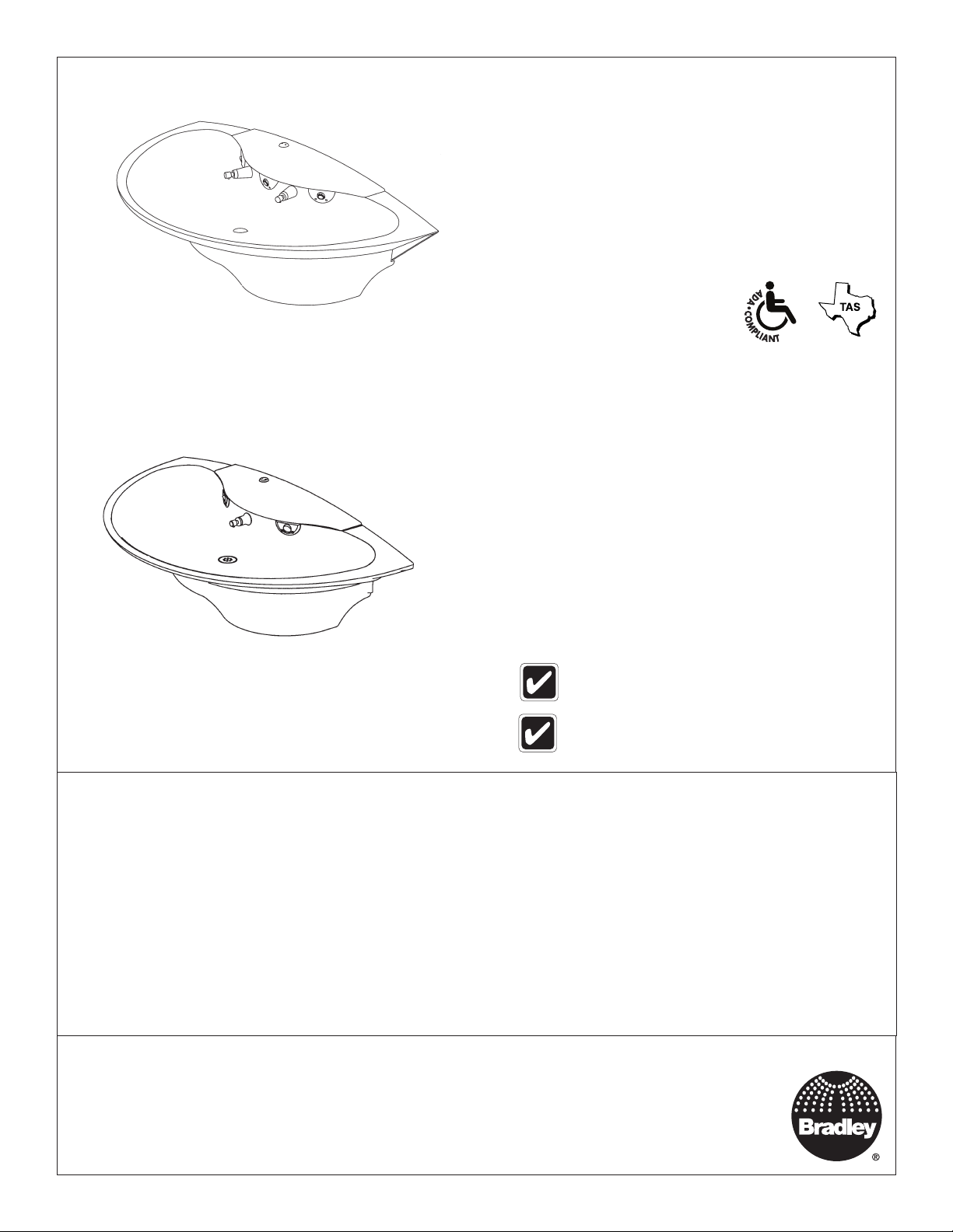
CRS-3/IR/LSD
Installation
CRS-2/IR, CRS-3/IR
Express® Crescent® Lavatory System
CRS-Series
Complies with Texas
Accessibility Standards (TAS)
for Juvenile Height applications.
Table of Contents
Dimensions ........................................................................ 2
Rough-Ins .......................................................................3-4
Supplies Required .............................................................5
Mount Bowl to Wall ............................................................ 5
Install Drain Spud ..............................................................5
Connect Supply .................................................................6
Electrical and Supply Connections .................................... 6
Adjust the temperature ......................................................7
Install Top Cover ................................................................7
Cleaning and Maintenance ................................................ 8
Solenoid Valve Troubleshooting and Repair Parts .............9
Navigator
®
Valve Troubleshooting and Repair Parts ........ 10
CRS-2/IR/LSD
3-station unit is shown throughout. 2-station
is similar.
For soap system installation, refer to
installation manual 215-1583.
WARNING
Flush all the water supply lines before making con nec tions. Debris in supply lines will cause the valves to
malfunction.
Hardware supplied by installer must be appropriate for wall construction. Wall anchors used must have a
minimum pull-out rating of 1,000 lbs.
IMPORTANT
Read this entire installation manual to ensure proper installation, then file these instructions with the owner
or maintenance department.
Product warranties may be found under “Products” on our web site at www.bradleycorp.com.
215-1330 Rev. N; ECN 16-08-022
© 2016 Bradley
Page 1 of 10 11/3/2016
Menomonee Falls, WI 53052 USA
800 BRADLEY (800 272 3539)
P.O. Box 309
+1 262 251 6000
bradleycorp.com
Page 2
CRS-2/IR, CRS-3/IR Installation
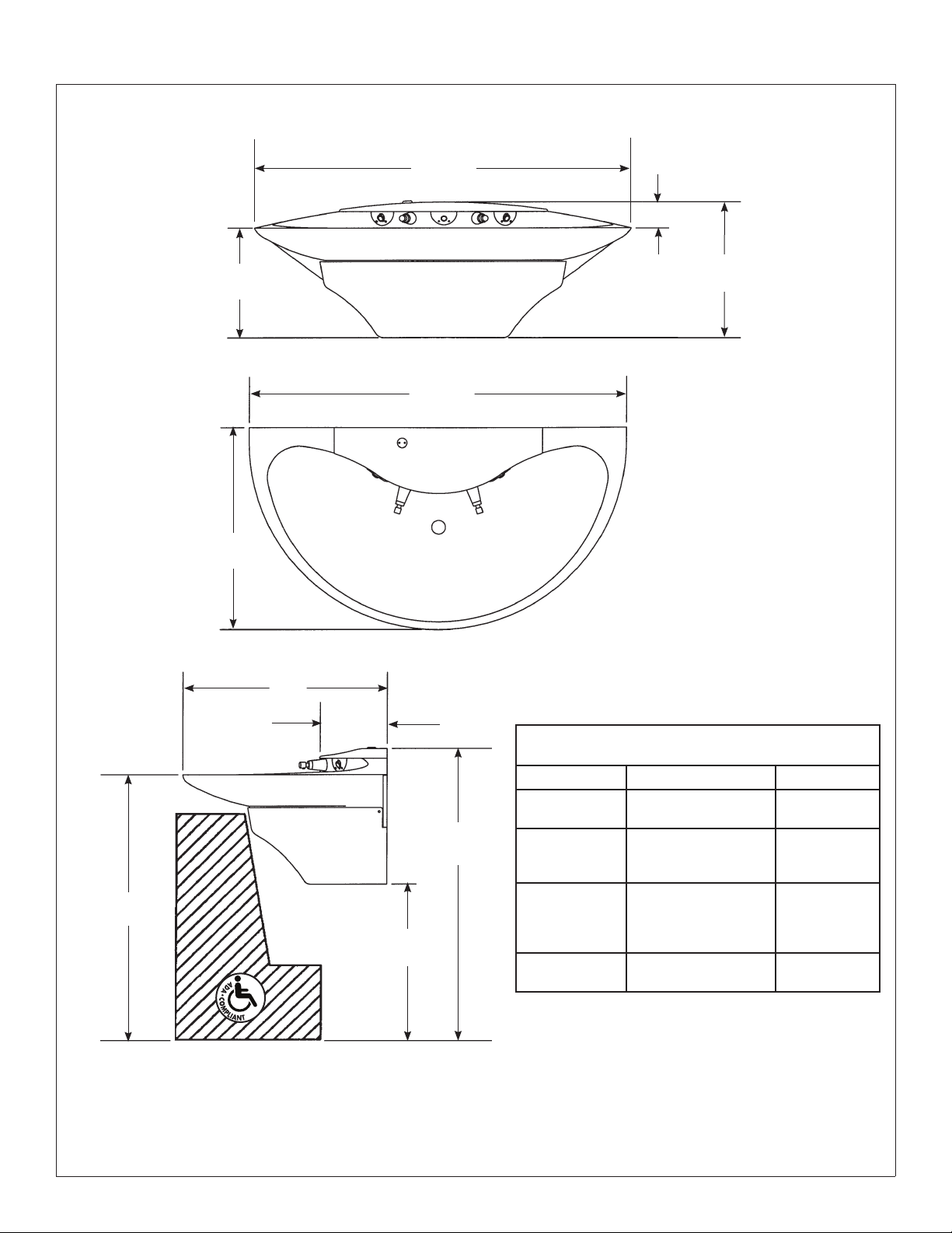
Express® Crescent® Lavatory System Dimensions
14"
(356)
26"
(660)
48"
(1219)
48"
(1219)
33⁄8"
(86)
(mm)
173⁄8"
(441)
*34"
(864)
26"
(660)
8-1/2"
(216)
*20"
(508)
*37-3⁄8"
(949)
*Adjustments to Vertical Dimensions
for Various Rim Heights
Rim Height Application Adjustment
34" Adult Height ADA,
TAS Adult Height
32" TAS Ages 11 thru 14
or 15, Grades 6
thru 8 or 9
30" TAS Ages 4 thru 10 or
11, Grades Pre-K thru
5 or 6 & Proposed
Juvenile Height ADA
24" Preschool (required
by some local codes)
None, as
shown
Subtract 2"
Subtract 4"
Subtract 10"
2 11/3/2016 Bradley • 215-1330 Rev. N; ECN 16-08-022
Page 3

Installation CRS-2/IR, CRS-3/IR
Rough-ins
WARNING Flush all the water supply lines before making connections. Debris in
supply lines will cause valves to malfunction.
Standard Height Mounting
Rim
Height
34"
(864)*
25-5/8"
(651)*
Trap Cover
(Optional)
1/2" NPT Drain
Stub Out 2" (51)
Centerline
of Fixture
(mm)
2"
(51)
6-1/2"
(165)
23-3/4"
(603)*
1/2" Nominal Copper
Tubing Hot and Cold
Supplies Stub Out 2" (51)
Floor
*Adjustments to Vertical Dimensions for Various Rim Heights
Rim Height Application Adjustment
34" Adult Height ADA, TAS Adult Height None, as shown
32" TAS Ages 11 thru 14 or 15, Grades 6 thru 8 or 9 Subtract 2"
30" TAS Ages 4 thru 10 or 11, Grades Pre-K thru 5 or 6 & Proposed Juvenile Height ADA Subtract 4"
24" Preschool (required by some local codes) Subtract 10"
Bradley • 215-1330 Rev. N; ECN 16-08-022 11/3/2016 3
Page 4

CRS-2/IR, CRS-3/IR Installation
Rough-ins cont’d.
Standard Height Mounting
10"
(254)
33-1/2"
(851)
31"
(788)
22-3/4"
(578)*
3-3/4"
(45)
(4) 1/4" Wall
Anchors for
Optional
Soap System
Optional 1/4"
Wall Anchor For
Trap Cover (Use
Trap Cover For
Template)
13-1/2"
(343)
7-11⁄16"
(195)
10"
(254)
(mm)
3⁄8" Wall Anchors (6) Places, Min.
Pull-Out Force 1,000 lbs. Per Anchor.
10"
(254)
13-1/2"
(343)
10-1/2"
(267)
110 Volt GFCI Protected
Electrical Outlet
(Recommended Location)
(Check Local Electrical
Codes Before Roughing In)
C
L
10"
(254)
35"
(889)*
27-1/4"
(692)
Floor
*Adjustments to Vertical Dimensions for Various Rim Heights
Rim Height Application Adjustment
34" Adult Height ADA, TAS Adult Height None, as shown
32" TAS Ages 11 thru 14 or 15, Grades 6 thru 8 or 9 Subtract 2"
30" TAS Ages 4 thru 10 or 11, Grades Pre-K thru 5 or 6 & Proposed Juvenile Height ADA Subtract 4"
24" Preschool (required by some local codes) Subtract 10"
4 11/3/2016 Bradley • 215-1330 Rev. N; ECN 16-08-022
Page 5

Installation CRS-2/IR, CRS-3/IR
Supplies required for installation
• (6) 3/8" wall anchors, bolts and washers to mount bowl to wall (min. pull-out force of 1,000 lbs.)
• 1/2" nominal copper tubing hot and cold or tempered supply piping
• 1-1/2" drain piping and P-Trap (available from Bradley, p/n 269-1697)
• 110 VAC power source for 110/12VDC regulated wall adapter (supplied)
• OPTIONAL TRAP COVER: 1/4" wall anchor, bolt and washer to mount trap cover to wall
• OPTIONAL: Bradley recommends installing an electrical cut-off switch to the unit (this feature prevents accidental
water delivery during regular maintenance and service)
1
Mount Bowl to the wall
WARNING Do not attempt to install the bowl alone. To prevent serious injury,
install the bowl with the assistance of another person and always
use appropriate lifting procedures.
Unpack bowl and cover assembly. Remove
wing nuts on the two threaded rods which
A
retain the cover. Remove the top cover
bracket and lift the cover off and set aside.
With 2 people, move the bowl assembly
to the wall using appropriate lifting
B
procedures, secure the bowl to the wall.
Level the bowl assembly with shims if
necessary and then tighten anchors.
C
Top Cover
Threaded Rod
(330-078)
Top Cover
Bracket
(140-852)
Wing Nut
(161-076)
2
Bradley • 215-1330 Rev. N; ECN 16-08-022 11/3/2016 5
Install Drain Spud
Assemble the P-trap (supplied by installer)
by connecting the 1-1/2" tubular pipe to the
1-1/4" tailpiece and to the 1-1/2" drain pipe
A
stubbed out of the wall
Strainer and
Tailpiece
(269-1584)
P-Trap
(Polyphopylene)
(269-1697)
Drain Assembly
1/4" Rubber
Washer
Fiber
Washer
Nut
Trim to Fit
Page 6

CRS-2/IR, CRS-3/IR Installation
3
Connect Supply
Connect the 1/2" compression female end
A
of the stop valves to the rough-ins.
Connect one end of the supply hoses to the
B
stop valves.
The hose attached to the hot water inlet
of the Navigator® TMV valve must be
connected to the hot water rough-in.
Connect the other end of the supply hoses
C
to the Navigator TMV valve assembly.
Optional Single Tempered Supply: Attach
the stop valve to the 1/2" tempered supply
line. Connect the stop alive to the solenoid
D
valve with the flexible supply hose.
The thermostatic mixing valve requires at least 115° water from the hot water side from
proper operation. As with all lavatories, there will be a delay in obtaining warm water. If the
hot water is too far away from the unit, a circulating pump may be required.
Navigator Mixing Valve
Cold Supply Inlet
Valve Mounting
Bracket
Navigator
Mixing Valve
Hot Supply
Inlet
Hot
Supply
Flexible
Supply
Hose
Cold
Supply
Stop Valve
4
Electrical and Supply Connections
CAUTION The adaptive infrared control must be connected with a 12VDC regulated wall adapter.
Connections to 110VAC will result in damage to the electronics and can cause personal injury.
NOTICE! Connection of leads other than shown may cause permanent damage to the sensor.
Compliance and conformity to local codes and ordinances is the responsibility of the installer.
The solenoid valves have been pre-wired.
Snap each sensor circuit plug into the
associated solenoid circuit plug located on
A
the valve bracket.
Snap the wall adapter barrel plug into the
barrel plug located on the valve bracket
B
wire harness.
Black Supply Tube
(From Sprayhead)
Green Supply Tube
(From Sprayhead)
Red Supply
Tube (From
Sprayhead)
Compression
Nut
(110-231)
Supply Inlet
Navigator Thermostatic
Mixing Valve
6 11/3/2016 Bradley • 215-1330 Rev. N; ECN 16-08-022
Page 7

Installation CRS-2/IR, CRS-3/IR
5
6
Adjust the Temperature
WARNING This valve is NOT factory
preset. Upon installation,
the temperature of this
valve must be checked and
adjusted to ensure delivery
of a safe water temperature.
Water in excess of 110°F
(43°C) may cause scalding.
Install the Optional Soap Dispenser
For Express Crescent Lavatory System units with an optional soap dispenser, see
installation manual 215-1583 for instructions on installing the soap dispenser.
Loosen Cap Screw about 1/4" (4-6
turns) and lift up cover (do not
A
remove).
Using cover, turn cartridge gently until
desired water temperature is reached.
B
Do not turn past stops as this may
damage unit. Push cover down and
tighten screw.
After testing is complete, reinstall
panel to frame.
C
H
C
7
Install the Top Cover
Carefully place the top cover on top of
the lavatory system bowl.
A
Install the threaded rods into the holds
on the bottom of the top cover.
B
Slide the anchor plate onto the threaded
rods and secure anchor plate against
C
bowl using the wing nuts provided.
Optional Soap Dispenser: Install
soap filler assembly in mounting
bracket previously installed. Tighten
D
the optional soap filler cap nut with a
spanner wrench.
Top Cover
Threaded Rod
(330-078)
Top Cover
Bracket
(140-852)
Wing Nut
(161-076)
Bradley • 215-1330 Rev. N; ECN 16-08-022 11/3/2016 7
Page 8

CRS-2/IR, CRS-3/IR Installation
Cleaning and Maintenance for Terreon® (Bowl and Cover)
Material Description: Terreon is an NAHB-certified densified solid surface material composed of polyester resin and is resistant
to chemicals, stains, burns and impact. Surface damage can be easily repaired with everyday cleansers or fine grit abrasives.
Routine Cleaning: Clean daily or as often as conditions require using a standard commercial or household cleaner such as
Formula 409® or Windex®.
®
Stubborn Stains: Remove tough stains with Ajax
circular motion with 240 grit wet/dry sandpaper. The finish can be renewed with a maroon Scotch-Brite pad.
Special Situations for Terreon Material
Scratches: Remove scratches with a green Scotch-Brite pad. The finish can then be renewed with a maroon Scotch-Brite pad,
followed by a white Scotch-Brite pad or 30-micron sandpaper.
Hard Water Deposits: Remove hard water deposits with a mild solution of vinegar and water. Always rinse the unit thoroughly
after cleaning.
Restoring the surface: Use Hope’s® Solid Surface cleaner and polish to refresh and protect the Terreon Solid Surface material.
Bradley recommends additional care and maintenance for the darker colored Terreon. For complete instructions on this additional
maintenance, visit bradleycorp.com.
NOTICE! Do not use strong acid or alkaline chemicals and cleansers to clean Terreon. If these chemicals
come in contact with the surface, wipe them off immediately and rinse with soapy water. Avoid
contact with harsh chemicals such as paint remover, bleach, acetone, etc. Avoid contact with hot
pans and objects.
Repair Kits: Terreon repair kits are available. Contact your Bradley representative or distributor for part numbers and pricing.
Repair kits are made to order and have a shelf life of 30 days.
, Comet®, or Soft-Scrub® and a green Scotch-Brite® pad or lightly sand in a
Terreon® is a unique, cast solid surface material. Aggregate flow and distribution as well as shades of color can
vary from product to product creating natural characteristics.
Cleaning and Maintenance for Stainless Steel
Material Description: Stainless steel is extremely durable, and maintenance is simple and inexpensive. Proper care, particularly
under corrosive conditions, is essential. Always start with the simplest solution and work your way toward the more complicated.
Routine cleaning: Daily or as often as needed use a solution of warm water and soap, detergent, or ammonia. Apply the
cleaning solution per the manufacturer's instructions and always use a soft cloth or sponge to avoid damaging the finish.
Stubborn Stains: To remove stains from stainless steel use a stainless steel cleaner and polish such as Ball® stainless steel
cleaner or a soft abrasive. Always follow the manufacturer's instructions and apply in the same direction as the polish lines.
NOTICE! Never use ordinary steel wool or steel brushes on stainless steel. Always use stainless steel wool
or stainless steel brushes.
Fingerprints and Smears: To remove fingerprints or smears use a high quality stainless steel cleaner and polish in accordance
with the manufacturer's instructions. Many of these products leave a protective coating that helps prevent future smears and
fingerprints.
Grease and Oil: To remove grease and oil use a quality commercial detergent or caustic cleaner. Apply in accordance to the
manufacturer's instructions and in the direction of the polish lines.
Precautions: Avoid prolonged contact with chlorides (bleaches, salts), bromides (sanitizing agents), thiocyanates (pesticides,
photography chemicals, and some foods), and iodides on stainless steel equipment, especially if acid conditions exist.
NOTICE! Do not permit salty solutions to evaporate and dry on stainless steel.
The appearance of rust streaks on stainless steel leads to the belief that the stainless steel is rusting. Look for the actual source
of the rust in some iron or steel particles which may be touching, but not actually a part of the stainless steel structure.
NOTICE! Strongly acidic or caustic cleaners may attack the steel causing a reddish film to appear. The use
of these cleaners should be avoided.
8 11/3/2016 Bradley • 215-1330 Rev. N; ECN 16-08-022
Page 9

Installation CRS-2/IR, CRS-3/IR
Troubleshooting – Solenoid Valve: Part nos. S07-067-DC (closed
body) & S07-067A-DC (thru body)
Turn off water supplies to the unit before troubleshooting.
Item Qty. Part No. Description
1 1 118-334 Valve Body, ¼" Closed
1 1 118-334A Valve Body, ¼" Thru
2 1 S27-352 12VDC Valve Cartridge
3 1 125-165 O-Ring, #2-013
3
2
1
Problem Cause Solution
An individual
operating
station fails
to shut off
and drips.
An individual
operating
station fails
to turn on.
Internal
cartridge
failure.
A failed
cartridge for
the valve or
loose electrical
connection to
the terminal.
Replace S27-352 cartridge.
Test the station to determine the cause.
1. Disconnect the wires from the cartridge of an adjacent valve. Disconnect the wires from the
problem valve and reconnect to the adjacent valve.
2. Turn on electrical and water supplies to the unit. Pass your hand in front of the sensor of the
problem station, and the adjacent station should turn on.
If the adjacent station turns on and cycles normally, replace the cartridge on the problem valve.
If the adjacent valve fails to turn on, inspect the wires from the sensor cable and do the following:
• make sure there are no breaks and that the fully insulated disconnect terminals are firmly
crimped in place;
• turn off the electrical and water supplies;
• reconnect to the adjacent valve and turn on the water supplies to the unit;
• pass your hand in front of the sensor. If the station still fails to turn on, replace the sensor.
Bradley • 215-1330 Rev. N; ECN 16-08-022 11/3/2016 9
Page 10

CRS-2/IR, CRS-3/IR Installation
Thermostatic Mixing Valve Troubleshooting
Before attempting to troubleshoot the valve or disassemble the components, check for the following conditions:
• If stop valves are used, make sure that they are fully open.
• Make sure that the hot and cold inlet pipes are connected properly, and that there are no cross-connections or
leaking stop valves.
• Check the hot water heater output to make sure that it is at least 10° F above the set temperature.
Be sure to close the appropriate shut-off valves prior to disassembly of the valve and reopen the valves after inspection
and repair is complete.
Problem Cause Solution
External leaks. Damaged cartridge or O-rings. Replace cartridge with part number 269-1927
Improper water
Hot water supply is not 10° above desired set point. Increase hot water supply temperature
temperature or
temperature
fluctuation.
Valve temperature is not properly set. Adjust the temperature as shown on page 7, step 5.
Limited water flow. Dirt and debris have built up in the valve or strainer. 1. Check to make sure both hot and cold supplies are
connected to the Navigator mixing valve and that they
have water flow.
2. Remove cover and U-clip. Remove the cartridge and
clean the strainer. It is not required to grease cartridge,
however if desired, use silicone grease only. Do not
use grease on check valves.
1
Parts List
Item Part No. Description
2
3
1 160-463 Cap Screw 1
2 107-582 Cover 1
3 269-1927 Thermostatic Cartridge 1
4 198-014 Check Valve* 2
5 132-051 Retaining Ring* 2
6 118-319 Valve Body 1
7 146-079 U-Clip 1
* Included with Prepack S65-326
Quantity
S59-4000
5
4
Tempered Line Adapter Option
Part no. S39-804
(replaces S59-4000 if tempered
line is used)
Strainer
(173-028)
6
4
5
7
10 11/3/2016 Bradley • 215-1330 Rev. N; ECN 16-08-022
 Loading...