

Page 1

215-180 Rev. K; EN 00-569
Page 1 of 2
P.O. Box 309, Menomonee Falls, WI 53052-0309
TEL. 1-800-BRADLEY FAX 262-251-5817
http://www.bradleycorp.com
Adjustment Instructions and Parts List for the HFP V alve
Model No. S90-252 HFP
Model No. E90-252HFP
HFP Valve Adjustment Instructions
NOTE: Refer to the illustration and parts list on page 2.
1. Turn off the water supply to the HFP valve.
2. Insert a 3/16” hex wrench into the broached/hex end of the lifting stem (Item 8).
3. Holding the lifting stem (Item 8) in place, back off the stop nut (Item 21).
4. Back off the bar nut (Item 19) by turning the handle assembly (Item 1).
5. Tighten the bonnet nut (Item 3).
6. Run the bar nut (Item 19) down by turning the handle assembly (Item 1) until the bar nut
sits on the stainless steel washer (Item 2). Then back off the bar nut approximately 1/4"
turn until the handle assembly returns to its original position.
7. Tighten the stop nut (Item 21) down on the bar nut (Item 19).
8. Open the water supply line to the unit. Test for leaks and adequate water flow.
Troubleshooting Instructions for Valve Leakage
NOTE: Through normal daily usage the valve may begin to leak. If leakage occurs, follow the
procedure outlined below (refer to the illustration and parts list on page 2):
1. Turn off the water supply to the HFP valve.
2. Loosen the bonnet nut (Item 3) only. DO NOT loosen the stop nut (Item 21) or the bar
nut (Item 19).
3. Remove the bonnet nut (Item 3) and handle assembly (Item 1) to expose the lifting stem
(Item 8).
4. Check the condition of the faucet washer (Item 14) at the end of the lifting stem (Item 8).
If the faucet washer is scored or worn, replace it with a new one.
5. If the faucet washer (Item 14) is undamaged, or after replacing the faucet washer, reinsert the lifting stem (Item 8) into the casing pipe (Item 7). Care must be taken to make
sure the guide (Item 10) does not get hung up as the lifting stem is lowered.
6. Hand tighten the bonnet nut (Item 3).
7. Open the water supply line to the unit. Test for leaks and adequate water flow.
Page 2
Bradley Corporation • 215-180 Rev. K; EN 00-569
2
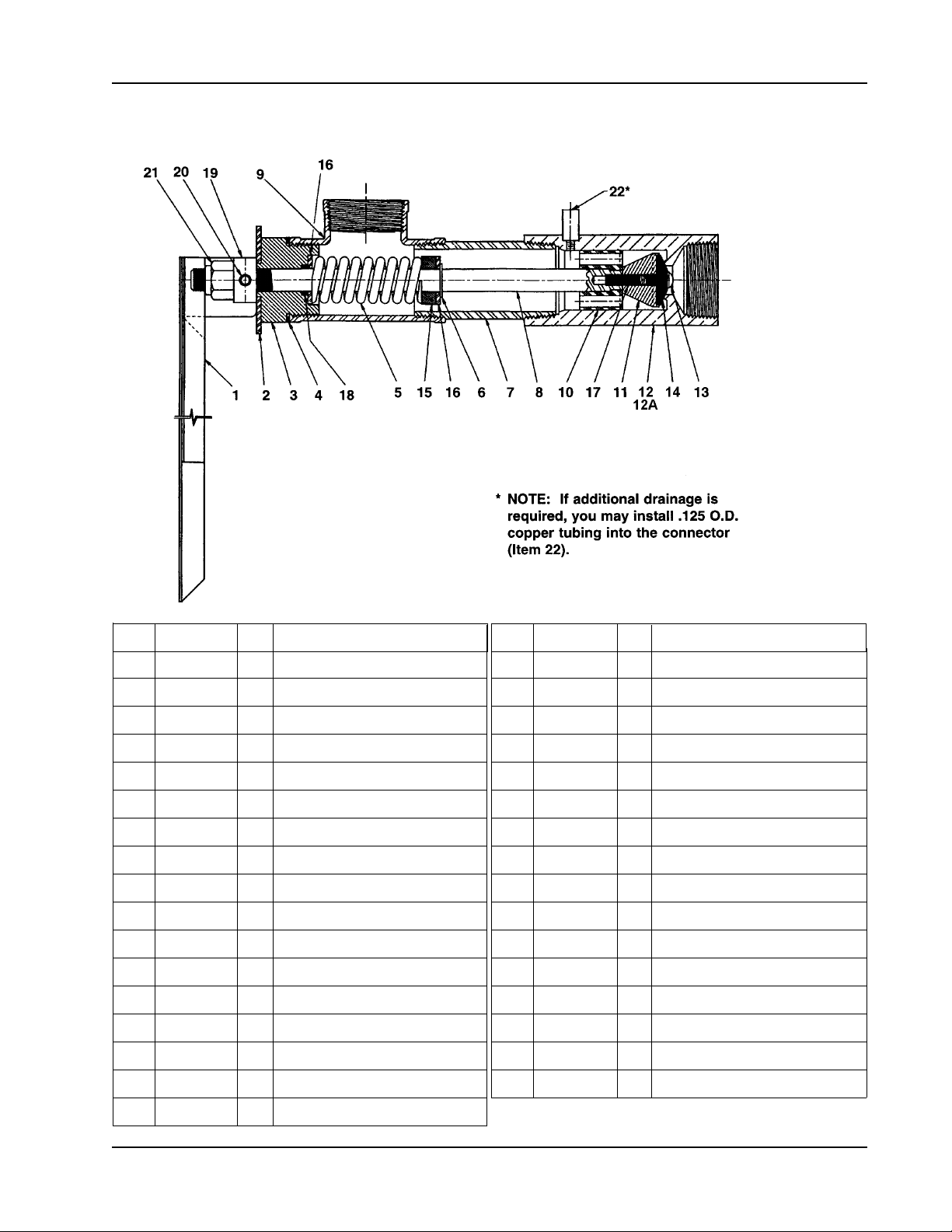
HFP Valve Parts Breakdown
1 S08-040 1 HANDLE ASSY.
2 142-002BB 1 STN. STL. WASHER
3 110-108 1 BONNET NUT
4 124-001BS 1 GASKET
5 135-001AP 1 SPRING
6 132-012 1 RETAINING RING
7 113-772 1 CASING PIPE (18" BURY DEPTH)
7 113-773 1 CASING PIPE (3' BURY DEPTH)
7 113-774 1 CASING PIPE (4' BURY DEPTH)
7 113-775 1 CASING PIPE (5' BURY DEPTH)
7 113-776 1 CASING PIPE (6' BURY DEPTH)
7 113-987 1 CASING PIPE (3' EUROPE)
8 120-022K 1 LIFTING STEM (18" BURY DEPTH)
8 120-022D 1 LIFTING STEM (3' BURY DEPTH)
8 120-022E 1 LIFTING STEM (4' BURY DEPTH)
8 120-022F 1 LIFTING STEM (5' BURY DEPTH)
8 120-022G 1 LIFTING STEM (6' BURY DEPTH)
8 120-022L 1 LIFTING STEM (3' EUROPE)
9 169-727A 1 TEE
10 145-072 1 GUIDE
11 132-011 1 RETAINER
12 118-246 1 VALVE BODYASSY.
12A 118-246B 1 VALVE BODY ASSY. EUROPE
13 160-138 1 MACHINE SCREW
14 169-920 1 FAUCET WASHER
15 182-061 1 SPACER
16 142-002CC 3 WASHER
17 160-251 1 SCREW STUD
18 125-001CD 1 O-RING
19 110-109 1 BAR NUT
20 165-038 2 ROLL PIN
21 161-061 1 STOP NUT
22 169-890 1 CONNECTOR
Item Part No. Qty Description Item Part No. Qty Description
Bradley Adjustment Instructions for the HFP Valve
Installation Instructions Model Nos. S90-252HFP, E90-252HFP
 Loading...