

Page 1
Installation
Instructions
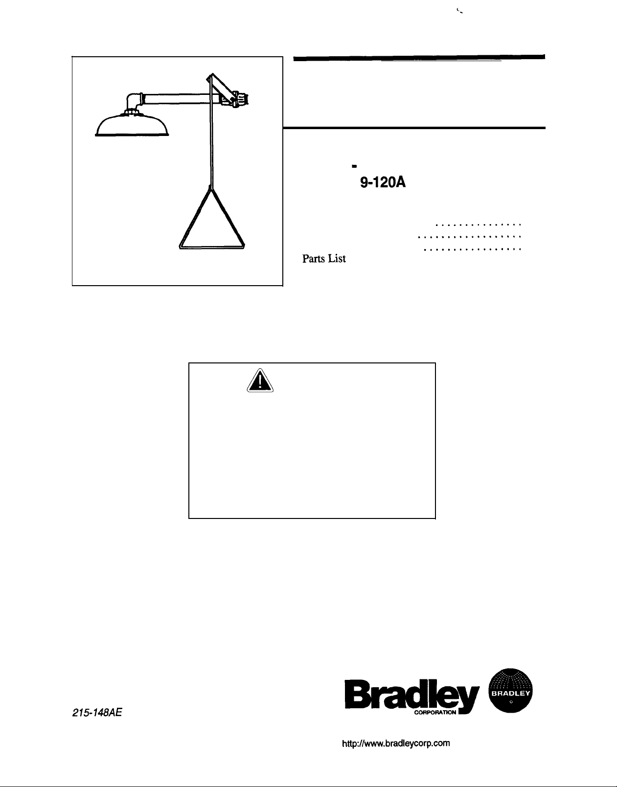
Bradley Drench
Shower
-
Horizontal Supply
Model E1
9-120A
Table of Contents
Pre-Installation Information
Installation Instructions
Assembly of Components
PartsList
IMPORTANT
This equipment should be inspected,
tested, and recorded weekly to maintain
proper operation.
Main water supply to the eye wash
should be “ON” at all times.
This installation manual and parts list
should be filed by the building owner’s
maintenance department.
.............................
..................
.................
...............
2
3
4
4
215-148AE
Page 1 of 4
Ref. G; EN 98-579
PO. Box 309, Menomonee Falls, WI USA 53052-0309
PHONE (414) 251-6000 FAX (414) 251-5617
http:/lwww.bradleycorp.com
Page 2
Bradley Drench Shower - Horizontal Supply
Model No.
E19-120A
Installation Instructions
Pre-Installation Information
Operation
The drench shower is easily activated by pulling the triangular pull rod downward, and
deactivated by pushing the triangular pull rod upward.
Components
Showerhead:
Shower Valve:
triangle handle.
Water Supply:
Pipe
and Fittings:
Check Contents
Separate all parts from packaging and check each part with Figure 2 and the Parts List on
page 4. Make sure all parts are accounted for before discarding any packaging material. If any
parts are missing, do not attempt to install your Bradley Drench Shower until you obtain the
missing parts.
The corrosion-resistant stainless steel showerhead has a 254 mm (10”) diameter.
The 1” IPS stay-open valve is operated by a stainless steel pull rod with a
Water supply connection is 1” BSP horizontal.
Pipe and fittings are galvanized steel, coated with
BradtectTM
safety yellow.
Bradley Drench Shower Warranty
Bradley Corporation warrants to commercial and institutional purchasers only each fixture free from defects in
material and workmanship under normal use and service upon the following terms and conditions:
1. We will replace, without charge, any part which proves to be defective within one year from
invoice at our option, F.O.B. Menomonee Falls, Wisconsin.
2. This warranty does not cover installation or any other labor charge and does not apply to fixtures which have
been damaged by accident, abuse or improper maintenance.
3. The repair or replacement of the defective fixtures as stated in this warranty shall constitute the sole remedy
of the purchaser, and the sole liability of the Bradley Corporation under this warranty. Bradley Corporation
shall not otherwise be liable under any circumstances for incidental, consequential or indirect charges caused
by defects in fixtures or any delay in the repair or replacement thereof.
4. This warranty extends only to commercial and institutional purchases and does not extend to any others,
including consumer, customers of commercial and institutional purchasers.
5. This warranty is in lieu of all other warranties expressed or implied, including any implied warranty of merchants ability or fitness for a particular purpose, or otherwise.
6. Bradley emergency fixtures are to be used as a supplement to first aid treatment. Bradley Corporation cannot
guarantee
or prior injuries. No other warranties, expressed or implied are authorized, provided or guaranteed by
Bradley Corporation.
that
when used this emergency equipment will prevent serious injury or the aggravation of existing
the
date of our
2
Bradley Corporation l 2%148AE
Ref. G; EN 98-579
Page 3

Installation Instructions
Installation Instructions
Supplies Required:
l
Pipe sealant
l
Piping to 1” BSP water supply inlet on unit
l
Adequate supply pipe supports
l
Minimum 102 mm (4”) drain to accommodate 115 liters per minute discharge for drench
shower waste
Bradley Drench Shower - Horizontal Supply
Model No.
E19-120A
Step 1: Assemble drench shower
I
NOTE: Flush the water supply line before beginning
installation.
1. Assemble drench shower components as shown
in Figure 2 on page 4.
2. Apply pipe sealant or tape (supplied by installer)
to all male-threaded pipe joints.
NOTE: Use a strap wrench around the pipes when
tightening to prevent mm-ring.
3. The
bottom edge of the showerhead should be
2134 mm
(7-O”)
from the floor.
-J
Step 2: Connect water supply
IMPORTANT: Do not rely on Bradley’s
Drench Shower to support
supply piping.
1. Connect water supply piping to l-1/4” BSP inlet on unit (piping supplied by installer).
Provide adequate supports (supplied by installer) for supply pipe using pipe hangers or
other means.
2. Mount safety sign to wall or pipe using sign mounting hardware supplied.
3. Open water supply lines. Test for leaks and adequate water flow.
Figure 1
Bradley Corporation l 215148AE
Ref.
G; EN 98-579
Installation Instructions
continued..
.
3
Page 4

Bradley Drench Shower - Horizontal Supply
Model No.
EM-120A
Installation Instructions
Assembly of
Comk3onents
1” BSP SUPPLY INLET
Figure 2
IService
ITEM
1
1A 142-002DC
1c
1D
1E
2
3
4
4A 187-053
48
l
Not Shown
Parts List
PART NO.
S30-059
S27-278
128-129
140-720
113-005LKE
189-723
S24-084E
155-008
I
i
0
4c
QTY.
DESCRIPTION
1
STAYaPEN
1
LOCKWASHER
1
1”
BALL VALVE
1
HANDLE
1
STOP
1
PIPE 1” IPS
1
90” STREET ELBOW1’IPS
1
STN. STL SHOWERHEAD ASSY. 8’
1
SHOWERHEAD SHELL 9 153-298
1
DIFFUSER
BALL
BRAcKEl
VALVE
ITEM PART NO.
4c 180-138
4D 153-235
4E 125-OOlDP
4F 157-005
5*
S45-314
8 12&158A
r
204-421
114-05OE
10
110-214
QTY.
DESCRIPTION
2 SCREW
1
ADAPTER
1
WASHER
4 DIFFUSER PADS
1
SIGN-MOUNTING HARDWARE
1
PULL ROD - 809mm LONG
1
EMERGENCY TAG
1
SAFETY SIGN
1
BSP
1
JAM
ADAPTOR
NUT
4
Bradley Corporation l 215148AE Ref. G; EN 98-579
 Loading...