

Page 1
Installation
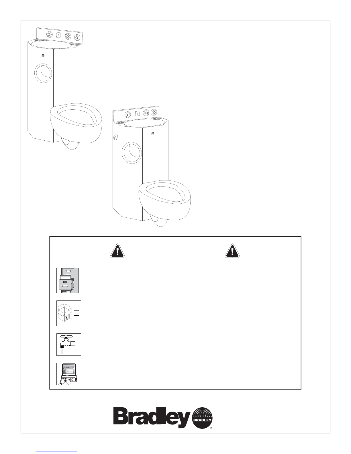
COMBI5500
17" Chase-Mounted Five-Sided
Stainless Steel Combination Unit
Table of Contents
Supplies Required ...........................2
Rough-In Information ...................... 2, 3
Installation Instructions .......................3
Cleaning Instructions ......................... 4
Bradley Security Fixtures are tamper resistant. All mounting hardware
Installation
THIS
SIDE
UP
215-329 Rev. K EN 08-703
© 2008 Bradley Corporation
Page 1 of 4 9/30/08
provided is essential for properly anchoring the unit. Bradley cannot
assume any responsibility for any improperly installed units. Read this
entire installation manual to ensure proper installation. When fi nished
with the installation, fi le this manual with the owner or maintenance
department. Compliance and conformity to local codes and ordinances is
Packing List
the responsibility of the installer.
•
•
•
•
Separate parts from packaging and make sure all parts are accounted for
before discarding packaging material. If any parts are missing, do not begin
installation until you obtain the missing parts.
Make sure that all water supply lines have been fl ushed and then completely
turned off before beginning installation. Debris in supply lines can cause
valves to malfunction.
Product warranties may be found under “Products” on our web site at
bradleycorp.com.
IMPORTANT!
P.O. Box 309, Menomonee Falls, WI 53052-0309
Phone: 1-800-BRADLEY Fax: 262-253-4161
www.bradleycorp.com
Page 2
COMBI5500 Installation
Supplies Required:
• 1" NPT supply piping to flush valve
• Toilet/Lav waste connections
• For optional air valve manifold: 1/2" NPT supply piping. Refer to Bradley Installation Manual (215-1158) provided with assembly.
• For optional self-closing valve: 1/2" NPT supply piping. Refer to Bradley Installation Manual (215-581) provided with assembly.
• For optional TouchTime
®
solenoid valve: 1/8" NPT supply piping; wire nuts sized for 22 AWG to connect to 24 VAC power source.
Refer to Bradley Installation Manual (215-1378) provided with assembly.
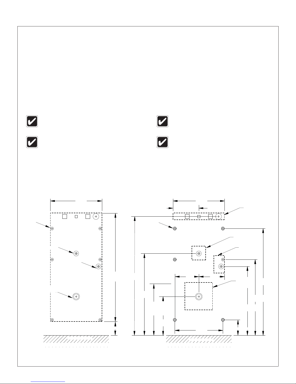
Roughing-In Supplies, Drain, and Waste Outlet
Threaded
Studs (6)
All views are from the fi xture side
(right-hand unit shown).
Rough-in 1-1/4" or 1-1/2" NPT (size dependent
on options ordered) lavatory waste outlet at the
dimensions shown below. Use single or multiple
openings, depending on site requirements.
15"
(381)
Lav Waste
7/8" (22)
Dia. Holes [5]
7-1/2"
(190)
Top of integral seat is to be mounted 15" ( 381 mm)
above fi nished fl oor.
On fl oor outlet waste units, centerline of
waste is 4-1/4" (108mm) from wall.
(mm)
15"
(381)
2" X 15" (51 x 381)
Valve Mounting Hole
4" (102)
Square Hole
3" x 5"
(76 x 127)
Hole
Flush Valve
Supply
Toilet
Waste
Finished Floor
Single Opening in Wall* Multiple Openings in Wall
*Recommended when using optional wall sleeve
2 9/30/08 Bradley Corporation • 215-329 Rev. K; EN 08-703
31-1/2"
(800)
4" (102)
34-1/2"
(876)
23-3/4"
(603)
15" (381)
Top of
Integral
Seat
11-1/4"
(286)
7"
(178)
Finished Floor
14"
(356)
7-3/4"
(197)
8" (203)
Square
Hole
4-1/2" (190)
20"
(508)
22"
(538)
31"
(787)
Page 3

Installation COMBI5500
Five-Sided Unit Dimensions
3-1/2"
(89)
12-1/4"
(311)
18"
(457)
COMBI55000 Series
(Center Confi guration)
17"
(432)
14"
(356)
4-1/4"
(108)
Floor
Waste
Option
Top View
23-3/8"
(721)
3-1/2"
(89)
18"
(457)
14"
(356)
COMBI55000 Series
(Angle Confi guration)
23-1/2"
(597)
12-1/4"
(311)
16-1/2"
(418)
4-1/4"
(108)
Floor
Waste
Option
17"
(432)
19-11/16"
(500)
32-1/2"
(826)
3-1/8" (79)
Wall-Mounted
Units Only
Install Unit
1
B
C
15"
(381)
Insert six 1/2"-13 threaded studs (supplied by
installer) into the back of the unit and screw in
A
approximately 1/2".
Connect the flush valve supply pipe, lav waste,
and toilet waste (supplied by installer) to the
couplings located on the back of the fixture.
Sliding studs and pipes through the wall openings,
position the fixture in place (top of integral toilet seat
is 15" above finished floor). Mount Valve Asembly.
Secure the fixture to the wall using anchor
brackets, washers, and nuts provided.
D
All fasteners must be securely
tightened to approximately 30 ft./lbs.
Side View
32-1/2"
(826)
15"
(381)
3-1/8" (79)
Wall-Mounted
Units Only
Mounting
Channel
(140-558)
Valve
Mounting
Plate
(159-292)
1/2" -13 Threaded Stud
0" - 4" Wall (109-039)
4" - 8" Wall (109-040)
8" - 12" Wall (109-048)
When fi nished, turn on the water supplies and check for
leaks and adequate water fl ow. Activate lavatory pushbuttons
and fl ush valve several times to purge air from the lines.
Bradley Corporation • 215-329 Rev. K; EN 08-703 9/30/08 3
Nut
(110-119)
Washer
(140-002AM)
Page 4

COMBI5500 Installation
Cleaning Stainless Steel
Material Description: Stainless steel is extremely durable, and maintenance is simple and inexpensive. Proper care, particularly
under corrosive conditions, is essential. Always start with the simplest solution and work your way toward the more complicated.
Routine Cleaning: Daily or as often as needed use a solution of warm water and soap, detergent, or ammonia. Apply the cleaning
solution per the manufactures instructions and always use a soft cloth or sponge to avoid damaging the fi nish.
Stubborn Stains: To remove stains from stainless steel use a stainless steel cleaner and polish such as Ball® stainless steel
cleaner or a soft abrasive. Always follow the manufactures instructions and apply in the same direction as the polish lines.
Never use ordinary steel wool or steel brushes on stainless steel. Always use stainless steel wool or stainless
steel brushes.
Special Situations for Stainless Steel Material
Fingerprints and Smears: To remove fi ngerprints or smears use a high quality stainless steel cleaner and polish in accordance
with the manufactures instructions. Many of these products leave a protective coating the helps prevent future smears and
fi ngerprints.
Grease and Oil: Grease and Oil : To remove grease and oil use a quality commercial detergent or caustic cleaner. Apply in
accordance to the manufactures instructions and in the direction of the polish lines.
Precautions: Precautions: Avoid prolonged contact with chlorides (bleaches, salts), bromides (sanitizing agents), thiocyanates
(pesticides, photography chemicals, and some foods), and iodides on stainless steel equipment, especially if acid conditions
exist.
Do not permit salty solutions to evaporate and dry on stainless steel.
The appearance of rust streaks on stainless steel leads to the belief that the stainless steel is rusting. Look for the actual source
of the rust in some iron or steel particles which may be touching, but not actually a part of the stainless steel structure.
Strongly acidic or caustic cleaners may attack the steel causing a reddish fi lm to appear. The use of these
cleaners should be avoided.
Brand Names
Use of brand names is intended only to indicate a type of cleaner. This does not constitute an endorsement, nor does the omission
of any brand name cleaner imply inadequacy. Many products named are regional in distribution, and can be found in local
supermarkets, department and hardware stores, or through your cleaning service. It is emphasized that all products should be used
in strict accordance with package instructions.
4 9/30/08 Bradley Corporation • 215-329 Rev. K; EN 08-703
 Loading...