

Page 1
Installation
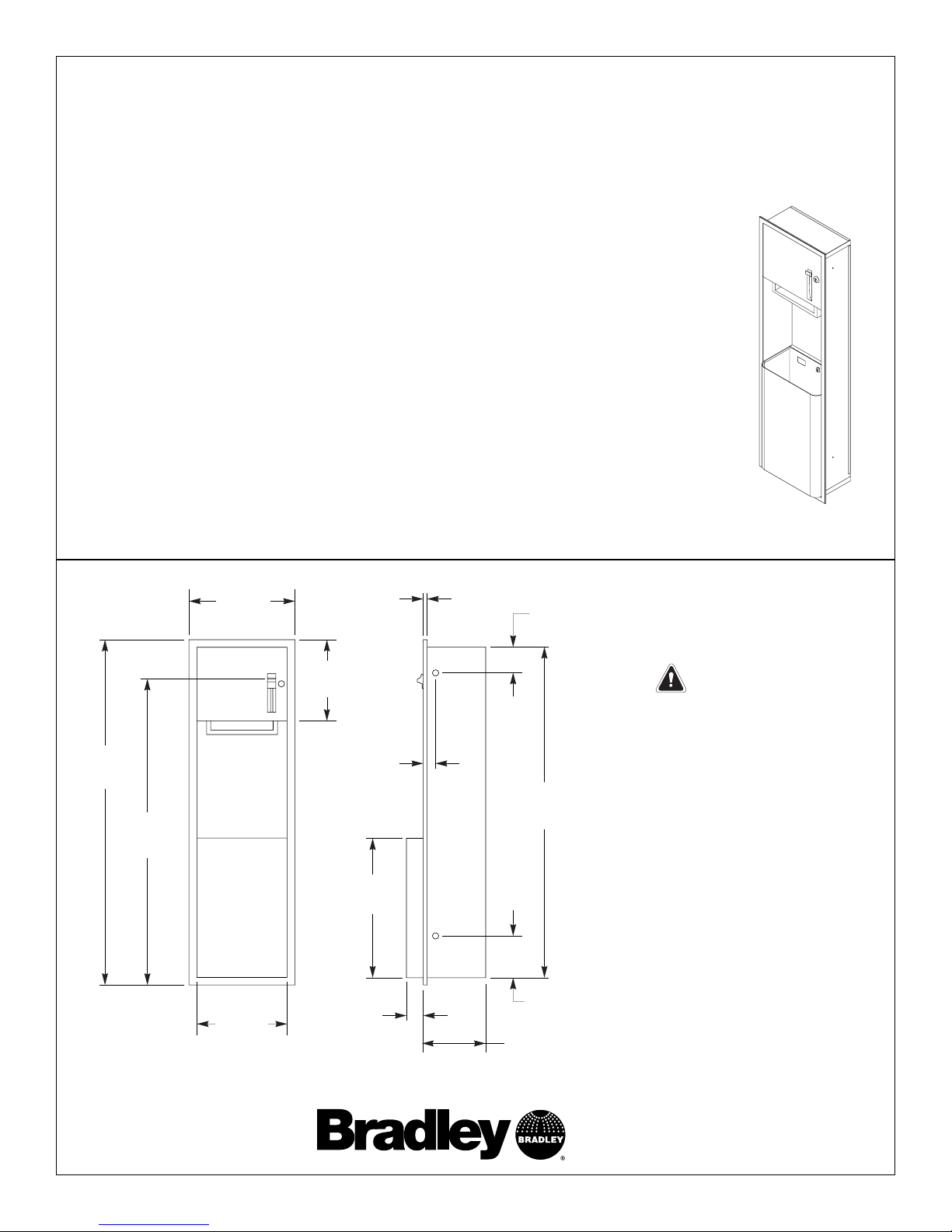
Semi-Recess and Recess-Mounted Towel/Waste Unit
NOTE: For surface-mounted unit, refer to the instructions on page 2.
NOTE: Coordinate installation with architect and contractor to avoid protrusion
from opposite wall, pipes vent, conduits, electrical wiring etc. in wall. Grounding
is recommended for plaster wall installation. If installing where unit projects
above top of wainscot, provide aluminum channel or other filler to prevent gap
from finished wall and flange of unit. For block walls, use metal expansion shields
(not provided).
1. Provide the wall opening per the dimensions shown in Figure 1.
2. Position the unit into the opening, unlock the door and remove the waste can.
NOTE: Shims may be required to prevent distortion when positioning the unit into
the wall opening. Place shims at the mounting holes between the outside of the
unit and the wall before securing the towel/waste unit.
3. Secure the unit to wall through the concealed mounting holes provided with
the four #10 screws supplied.
15-1/8"
(384mm)
54-1/8"
(1375mm)
17-1/8"
(435mm)
56"
(1423mm)
10-1/2"
(267mm)
50-1/2"
(1283mm)
7"
(178mm)
12"
(305mm)
1/4"
(6mm)
2-5/16"
(59mm)
4-1/8"
(105mm)
3"
(76mm)
23"
(584mm)
Figure 1
IMPORTANT
For ADA Accessibility compliance
• the unit should be installed so
that the top of the wall opening
is 73" (1854mm) maximum
above the finished floor (AFF)
if additional clear-floor sidereach access is provided, OR
67" (1701mm) maximum AFF if
only clear-floor forward-reach
access is provided.
• the unit cannot be located
where it will protrude into
walks, halls, corridors,
passageways or aisles.
P.O. Box 309, Menomonee Falls, WI 53052-0309
Phone: 1-800-BRADLEY Fax: (262) 251-5817
http:\\www.bradleycorp.com
227 Towel Dispenser/Waste Unit
P20-164; EN 05-1512
© 2005 Bradley Corporation
Page 1 of 6 3/9/05
Page 2
Installation 227
2
Installation
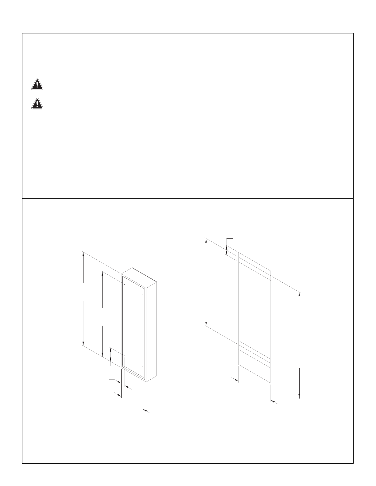
Surface-Mounted Towel/Waste Unit
NOTE: For semi-recess and recess-mounted unit, refer to the instructions on page 1.
IMPORTANT: Adequate in-wall backing must be provided by installer to fully support the
weight of the unit. Always check local codes and ordinances prior to installation.
IMPORTANT: Concealed mounting holes in back of the unit must be provided by installer
prior to installation. Refer to Figure 2 for suggested mounting hole locations.
1. Plaster or dry wall construction: Provide in-wall backing (suitable for use with #10 x 1"
screws) at the mounting slot locations shown in Figure 2 below.
Other wall surfaces: Provide fiber plugs or expansion shields (suitable for use with #8 x 1-1/4"
sheet-metal screws supplied by installer), OR provide 1/8" toggle bolts or expansion bolts. If
installing where unit projects above top of wainscot, provide aluminum channel or other filler to
prevent gap from finished wall to back of unit. For block walls, use metal expansion shields
(provided by installer).
2. Unlock the door and remove the waste can. Secure the unit to the wall through the concealed
mounting holes (provided by installer) with the hardware appropriate for your wall construction.
Bradley Corporation • P20-164; EN 05-1512 3/9/05
17-1/8"
(435mm)
56"
(1423mm)
42-1/2"
(1080mm)
CENTERLINE
OF BACKING
4" TYP
(102mm)
51"
(1295mm)*
8-1/2"
(216mm)*
14-13/16"
(376mm)*
2-1/4"
(57mm)*
CENTERLINE
OF BACKING
TO FLOOR
5'-0" MIN
(1524mm)
TO
6'-3" MAX
(1905mm)
* Suggested mounting hole
locations for installer
Figure 2
Page 3

Installation
Distributeur d'essuie-mains/Vide-déchets semi-encastré et encastré
REMARQUE : Pour l'unité montée en surface, se reporter aux instructions en page 4.
REMARQUE : Coordonner l'installation avec l'architecte ou l'entrepreneur pour éviter
toute saillie du mur opposé, des évents de tuyaux, conduits, câblage électrique, etc. dans
le mur. Une mise à la terre est recommandée pour toute installation dans un mur en
plâtre. Si une fois installée, l'unité doit surplomber le dessus du lambris, fournir une
moulure en aluminium ou toute autre garniture pour empêcher tout espace entre le mur
fini et la bride de l'unité. Pour les murs en blocs, utiliser des coquilles d'expansion
métalliques (non fournies).
1. Prévoir une ouverture murale conformément aux dimensions illustrées à la Figure 1.
2. Positionner l'unité dans l'ouverture, déverrouiller la porte et retirer la poubelle.
REMARQUE : Des cales sont peut-être nécessaires pour empêcher toute déformation lors
du positionnement de l'unité dans l'ouverture murale. Placer les cales au niveau des trous
de fixation entre l'extérieur de l'unité et le mur avant de fixer le distributeur d'essuiemains/vide-déchets.
3. Fixer l'unité au mur dans les trous de fixation dissimulés fournis à l'aide des quatre
vis n° 10 fournies.
15-1/8"
(384mm)
54-1/8"
(1375mm)
17-1/8"
(435mm)
56"
(1423mm)
10-1/2"
(267mm)
50-1/2"
(1283mm)
7"
(178mm)
12"
(305mm)
1/4"
(6mm)
2-5/16"
(59mm)
4-1/8"
(105mm)
3"
(76mm)
23"
(584mm)
Figure 1
IMPORTANT
Conformité d'accès facile ADA
(Americans with Disabilities Act)
• l'unité doit être installée de
manière à ce que le haut de
l'ouverture murale se trouve à
1 854 mm (73") maximum audessus du sol fini si un accès
supplémentaire latéral sol
dégagé est fourni OU à 1 701
mm (67") maximum au-dessus
du sol fini si seul un accès par
l'avant sol dégagé est fourni.
• l'unité ne peut être située dans
des endroits où elle fera saillie
dans les allées, les halls, les
corridors, les passages ou les
couloirs.
P.O. Box 309, Menomonee Falls, WI 53052-0309
Phone: 1-800-BRADLEY Fax: (262) 251-5817
http:\\www.bradleycorp.com
227 Distributeur
d'essuie-mains/Vide-déchets
P20-164; EN 05-1512
© 2005 Bradley Corporation
Page 3 of 6 3/9/05
Page 4

Installation 227
4
Installation
Distributeur d'essuie-mains/Vide-déchets monté en surface
REMARQUE : Pour l'unité semi-encastrée et encastrée, se reporter aux instructions en page 3.
IMPORTANT : Un support adéquat dans le mur doit être fourni par l'installateur pour
soutenir entièrement le poids de l'unité. Toujours vérifier les codes locaux et arrêtés
municipaux avant toute installation.
IMPORTANT : Des trous de fixation dissimulés dans le dos de l'unité doivent être fournis
par l'installateur avant toute installation. Se reporter à la Figure 2 pour voir les
emplacements suggérés des trous de fixation.
1. Construction murs en plâtre ou cloisons sèches : Prévoir un support dans le mur (convenant pour
l'emploi de vis n° 10 x 1") au niveau des emplacements de fentes de montage illustrés à la Figure 2 cidessous.
Autres surfaces murales : prévoir
des chevilles en fibre ou des coquilles d'expansion (convenant
pour l'emploi de vis à tôle n° 8 x 1-1/4" fournies par l'installateur) OU prévoir des boulons à ailettes ou
des boulons à coquilles d'expansion de 1/8". Si une fois installée, l'unité doit surplomber le dessus du
lambris, fournir une moulure en aluminium ou toute autre garniture pour empêcher tout espace entre le mur
fini et le dos de l'unité. Pour les murs en blocs, utiliser des coquilles d'expansion métalliques (fournies par
l'installateur).
2. Déverrouiller la porte et retirer la poubelle. Fixer l'unité au mur dans les trous de fixation dissimulés
(fournis par l'installateur) avec la visserie appropriée à la construction murale.
Bradley Corporation • P20-164; EN 05-1512 3/9/05
17-1/8"
(435mm)
56"
(1423mm)
42-1/2"
(1080mm)
CENTERLINE
OF BACKING
4" TYP
(102mm)
51"
(1295mm)*
8-1/2"
(216mm)*
14-13/16"
(376mm)*
2-1/4"
(57mm)*
CENTERLINE
OF BACKING
TO FLOOR
5'-0" MIN
(1524mm)
TO
6'-3" MAX
(1905mm)
* Suggested mounting hole
locations for installer
Figure 2
* Les emplacements suggérés des
trous de fixation (pour l'installateur)
42-1/2"
(1080mm)
axe de
support
axe de
support
du sol
5'-0"
(1524mm)
du
6'-3"
(1905mm)
Page 5

Instalación
Unidad para toallas/desechos semiempotrada y empotrada
NOTA: Para la unidad montada superficialmente, consulte las instrucciones de la página 6.
NOTA: Coordine la instalación en el muro con un arquitecto o con un contratista a fin de
evitar que la unidad sobresalga del muro opuesto, de la ventilación de las tuberías,
conductos, cableado eléctrico, etc. Se recomienda aplicar una capa de imprimación para
las instalaciones en muros de yeso. Si se realiza la instalación en sitios en que la unidad
se proyecta por sobre la parte superior del friso de madera, disponga un perfil de
aluminio en U o algún otro relleno que evite la aparición de una brecha entre el muro
terminado y el reborde de la unidad. Para los muros en bloques, utilice escudos
ensanchadores de metal (no incluidos).
1. Disponga la abertura del muro de acuerdo con las dimensiones que aparecen en la
Figura 1.
2. Ubique la unidad en la abertura, abra la puerta y saque el basurero.
NOTA: Es posible que se necesiten cuñas que eviten la distorsión al momento de ubicar la
unidad en la abertura del muro. Coloque las cuñas en los orificios de montaje entre la
parte exterior de la unidad y el muro antes de fijar la unidad para toallas/desechos.
3. Fije la unidad al muro a través de los orificios de montaje ocultos que se
proporcionan junto con cuatro tornillos Nº 10.
15-1/8"
(384mm)
54-1/8"
(1375mm)
17-1/8"
(435mm)
56"
(1423mm)
10-1/2"
(267mm)
50-1/2"
(1283mm)
7"
(178mm)
12"
(305mm)
1/4"
(6mm)
2-5/16"
(59mm)
4-1/8"
(105mm)
3"
(76mm)
23"
(584mm)
Figura 1
IMPORTANTE
Para cumplir con las normas de
ADA relacionadas con la
accesibilidad
• la unidad se debe instalar de
modo que la parte superior de
la abertura del muro esté a un
máximo de 1854 mm (73 pulg.)
por sobre el piso acabado
(AFF, por sus siglas en inglés)
si se dispone un acceso con
alcance lateral en el piso
despejado, O a un máximo de
1701 mm (67 pulg.) por sobre el
piso acabado si sólo se
dispone un acceso con alcance
hacia delante en el piso
despejado.
• la unidad no puede ubicarse en
lugares en que sobresalga
hacia pasillos, salones,
corredores, pasadizos ni
galerías.
P.O. Box 309, Menomonee Falls, WI 53052-0309
Phone: 1-800-BRADLEY Fax: (262) 251-5817
http:\\www.bradleycorp.com
227 Dispensador de toallas/recipiente
para desechos
P20-164; EN 05-1512
© 2005 Bradley Corporation
Page 5 of 6 3/9/05
Page 6

Installation 227
6
Instalación
Unidad para toallas/desechos montada superficialmente
NOTA: Para la unidad semiempotrada y empotrada, consulte las instrucciones de la página 1.
IMPORTANTE: El instalador debe disponer refuerzos en el interior del muro a fin de que soporte
completamente el peso de la unidad. Revise siempre los códigos y ordenanzas locales antes de
una instalación.
IMPORTANTE: El instalador debe proporcionar orificios de montaje ocultos en la parte posterior
de la unidad antes de la instalación. Consulte la Figura 2 para conocer las sugerencias de
ubicaciones para los orificios de montaje.
1. Muros secos y de yeso: Disponga refuerzos en el interior del muro (que sirva para tornillos Nº 10 x 1
pulg.) en los lugares en que irán las ranuras de montaje que aparecen en la Figura 2 a continuación.
Otros tipos de pared: Disponga tapones de fibra o escudos ensanchadores (que sirvan para tornillos Nº 8
x 1-1/4 pulg. para lámina metálica, que proporciona el instalador), O disponga pernos acodillados o de
expansión de 1/8". Si se realiza la instalación en sitios en que la unidad se proyecta por sobre la parte
superior del friso de madera, disponga un perfil de aluminio en U o algún otro relleno que evite la
aparición de una brecha entre el muro terminado y la parte posterior de la unidad. Para los muros en
bloques, utilice escudos ensanchadores de metal (proporcionados por el instalador).
2. Abra la puerta y saque el basurero. Fije la unidad al muro a través de los orificios de montaje ocultos (que
proporciona el instalador), con el equipo adecuado para la construcción de su muro.
Bradley Corporation • P20-164; EN 05-1512 3/6/05
17-1/8"
(435mm)
56"
(1423mm)
42-1/2"
(1080mm)
CENTERLINE
OF BACKING
4" TYP
(102mm)
51"
(1295mm)*
8-1/2"
(216mm)*
14-13/16"
(376mm)*
2-1/4"
(57mm)*
CENTERLINE
OF BACKING
TO FLOOR
5'-0" MIN
(1524mm)
TO
6'-3" MAX
(1905mm)
* Suggested mounting hole
locations for installer
Figura 2
* Las sugerencias de ubicaciones
para los orificios de montaje (para
el instalador)
42-1/2"
(1080mm)
linea central
del apoyo
linea central
del apoyo
au suelo
5'-0"
(1524mm)
au
6'-3"
(1905mm)
 Loading...